1
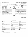
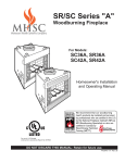
GARFIELD COUNTY BUILDING PERMIT APPLICATION
108 8 '" Street, Suite 401, Glenwood Springs, CO 81601
I Fax: 970-384-3470 1 Inspection Line: 970·384-5003
Phon~L~0-945-8212
t010 -
Permit No:
IJob Address: 3 l\
1
Lot No:
\2.1verWt
Jon tractor:
4
Architect/Engineer:
5
Sq. F't. ofBuilding: (
(i
Use of Building:
un.n ~oUs
Describe
~ 1.
1
1
;;
I
?=h
· lt'-\el e
v
Class of Work:
~
3
/'
Address:
Ph:
Lie. No.
Height:
No. :::iloors:
?5!It: L/
wood-D bJ
r (\~
New
G,
(o'(
t\.0\
_,
0
Driveway Permit
11 Valuation of Work: $
D
/I ~ ~ 0
Lie. No.
b:,i eJ~t woLd 'pv f
Carport:
On -Site Sewage
Disposal
0
~
fl :
r\
o Remove
D "Iteration
Addition · Move
IJY Single
0
d
~~:2~~ -22.1{~
Double
10
'h
've...r e n
1l10--q~t\ - 3\~i
~ J.:..'i+te
Address:2c~~~vaW \)(' Ph:
cr~o·- OJ,_<-\- 3\ 4 8
\..~
..·~ e.
Sq.
~rage:
~~
~lbl\~
Address~ ~\\1e.rbc-n-\- Of
Sc\\s
3
7
N.ew CC\.stl e , co.
DrBlock No:
a \:J,.?;, - 3 4 3-..30 . D \.L.,.
Subd . I Exemption:\2-J
\{o
Owner~UO.n
2
Parcel/Sch edule No:
_
D
0
G
v
{ '
Single
Double
Site Plan
Adj usted Valuations: S
12 Special Conditions:
NOTICE
A SEPARATE ELECTRICAL PERMIT IS REQUIRED AND M UST BE
ISSUED BY T HE STATE OF COLORADO.
I
I
Plan
Check ~~;
,...,
Permit Fee :
'-1710
TillS PERMIT BECOMES NULL AND VOID IF WORK OR CONSTRUCTION
AUTHORIZED IS NOT COMMENCED WITHLN 180 DAYS, OR. IF
CONSTRUCTION OR WORK IS SUSPENDED OR ABANDONED FOR A
PERIOD OF ! 80 DAYS AT ANY TIME AFTER WORK IS COMMENCED.
Total F ee:
1HEREBY CERTIFY THAT I HAVE READ AND EXAMINED THIS
APPLICATION AND KNOW THE SAME TO BE TRUE AND CORRECT. ALL
PROVISIONS OF LAWS GOVERNING THIS TYPE OF WORK WILL BE
COMPLETED WITHIN WHETHER SPECIFIED HEREIN OR NOT. THE
GRANTING OF A PERMIT DOES NOT PRESUME TO GNE AUTHORITY
TO VIOLATE OR CANCEL TilE PROVISIONS OF ANY OTHER STATE OR
LOCAL LAW REGULATING CONSTIRJCTION OR TH E PERFORMANCE
< F CONSTRUCTION. ~
OCC G roup :
Zoning:
Setb acks :
11_,-{}-CvV\
Manu . Home:
ISDS No. & Fee:
.
GNATU\ l r :\VNER
1
~l~h
~
tm
lf)_., \k - u/
PT.
l\L/DATE
q/2o/o~
PL1'o~E
/DATE
Canst. Type:
~c
~:Tf~ }0-\~ -<.~~
APP OV
'7llf OL(
Dated Permit Iss u ed:
[/
f%
AGREEMENT
PERMISSION IS HEREBY GRANTED TO THE APPLICANT AS 0\VNER. CONTRACTOR AND/OR THE AGENT OF THE CONTRACTOR OR OWNER TO CONSTRUCT
TilE STRUCTURE AS DETAI!,ED ON PLANS AND SPEC!F'ICAT!ONS SUBMITTED TO AND REVIEWED BY TH E BUILDING DEPARTMENT.
IN CONSIDERATION OF THE ISSSUANCE OF THIS PERMIT. TilE SIGNER H EREBY AGREES TO COMPLY WITH ALL BUILDING CODES AND LAND
USE REGULATIONS ADOPTED BY GARFIELD COUNW PURSUANT TO AUTHORIW GIVEN LN 30.28.201 CRS AS AMENDED. TilE SIGNER FURTilER AGREES
THAT IF' THE ABOVE SAID ORDINANCES ARE NOT FULLY COMPILED WJTIIIN TilE LCOATION, ERECTION. CONSTRUCTION. AND USE OF THE
ABOVE DESCRIBED STRUCTURE. THE PERMIT MAY BE REVOI{ED BY NOTICE FROM THE COUNW AND THAT THEN AND THERE IT SHALL BECOME
NULL AND VOID. THE ISSUANCE OF A PER.t\1T BASED UPON PLANS. SPECIFICATIONS AND OTHER DATA SHALL NOT PREVENT THE BUILDING OFFICIAL
FROM TilEREAFTER REQUIRING THE CORRECTION IJF ERRORS IN SAID PLANS. SPECIFICATIONS AND OTHER DATA OR FROM PREVENTING
BUI LDING OPERATION BEING CARRIED ON THEREUNDER WHEN IN VIOLATION OF THS CODE OR ANY OTH ER ORDINANCE OR REGULATION OF
THIS JURISDICTION. THE REVIEW OF SUBMITTED PLANS AND SPECIFICATIONS AND INSPECTIONS CONDUCTED THEREAFTER DOES NOT CONSTITUTE
AN ACCEPTANCE OF ANY RESPONSIBILITIES OR LIABLITIES BY GARFIELD COUNTY FOR ERRORS. OMISSIONS OR D!SCREPENC!ES. THE RESPONS!
BILIW FOR THESE ITEMS AND IMPLEMENTATION DURING CONSTRUCTION RESTS SPECIFIC!ALLY WITH THE ARTICTECT. DESIGNER. BUILDER.
AND OWNER. COMMENTS ARE INTENDED TO BE CONSERVATNE AND IN SUPPORT OF THE O WNERS LNTEREST.
1 HEREBY ACKNOWLEDGE THAT 1 HAVE READ AND UNDERSTAND THE AGREEMENT ABOVE (INITIAL):
v ,. 5
'
'
The following items are required by Garfield County for a final inspection:
1. A final Electrical Inspection from the Colorado State Electrical Inspector;
2. Permanent address assigned by Garfield County Building Department posted where readily
visible from access road;
3. A finished roof, a lockable house, complete exterior siding, exterior doors and windows
installed, a complete kitchen with cabinets, a sink with hot & cold running water, non-absorbent
kitchen floor coverings, counter tops and finished walls. ready for stove and refrigerator, all
necessary plumbing;
4. All bathrooms must be complete, with washbowl, tub or shower, toilet stool, hot and cold
running water, non-absorbent floors and walls finished and a privacy door;
5. All steps outside or inside over three (3) steps must have handrails, guard rails on balconies or
decks over 30" high constructed to all IBC and IRC requirements;
6. Outside grading done to where water will detour away from the building;
7. Exceptions to the outside steps, decks and grading may be made upon the demonstration of
extenuating circumstances, i.e. weather, but a Certificate of Occupancy will not be issued until
all the required items are completed and a final inspection made;
8. A final inspection sign off by the Garfield County Road & Bridge Department for driveway
installation, where applicable; as well as any final sign off by the Fire District, and/or State
Agencies where applicable.
9. If you will be connecting to a public water and/or sewer system, proof of the tap fees have been
paid and the connections inspected by the service provider prior to issuance of a C.O.
A CERTIFICATE oF OCCUPANCY WILL NOT BE ISSUED UNTIL ALL THE
ABOVE ITEMS HAVE BEEN COMPLETED.
****A CERTIFICATE OF OCCUPANCY MAY TAKEUP TO 5 BUSINESS DAYS TO BE
PROCESSED AND ISSUED.
****CANNOT OCCUPY OR USE DWELLING UNTIL A CERTIFICATE OF
OCCUPANCY (C.O.) IS ISSUED. OCCUPANCY OR USE OF DWELLING WITHOUT A
C.O. WILL BE CONSIDERED AN ILLEGAL OCCUPANCY AND MAY BE GROUNDS
FOR VACATING PREMISES UNTIL ABOVE CONDITIONS ARE MET.
I understand and agree to abide by the above conditions for occupancy, use and the issuance of a
Certificate of Occupancy for the dwelling under building permit# \ O}:C)
L\
Qgnature
Bpapplicationoctober2006
Date
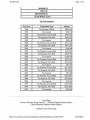
VALUATION/FEE DETERMINATION
Applicant_ _ _
S"'""""c)~\..:. .,:. .-~""-----:-----=Address._ _3
....~...."'.~,..
1 .....J.,;
(Z.;;..;l:...;;v~{ooL:;&
;;:;.;I.;;::;.
:J.;;;.;
od=.~......._
P..:..;
(L:;;....
Date_ _--~....:1t...:'J_-...:.\...:~~
-o
:::::.·J.....r...._ _ _ __
Finished (Livable Area):
Main
Upper
Lower
Other
Total Square Feet
Valuation
Basement:
Unfinished
Conversion of Unfinished to Finished
Plan Check Fee for Conversion
Valuation
Garage:
Valuation
Crawl Space:
Valuation
Decks/Patios:
Covered
Valuation
Open
Valuation
Total Valuation
Subdivision
Lot/Block
Contractor
GARFIELD COUNTY BUILDING AND PLANNING
970-945-8212
MINIMUM APPLICATION REQUIREMENTS
For
SINGLE FAMILY DWELLING CONSTRUCTION
Including
NEW CONSTRUCTION
ADDITIONS
ALTERATIONS
And
MOVED BUILDINGS
In order to understand the scope of the work intended under a permit application and expedite the
issuance of a permit it is important that complete information be provided. When reviewing a plan
and it's discovered tbat required information has not been provided by the applicant, this will result
in the delay of the permit issuance and in proceeding with building construction. The owner or
contractor shall be required to provide this information before the plan review can proceed. Other
plans that are in line for review may be given attention before the new information may be reviewed
after it has been provided to the Building Department.
Please review this document to determine if you have enough information to design your
project and provide adequate information to facilitate a plan review. Also, please consider
using a design professional for assistance in your design and a construction professional for
construction of your project. Any project with more than ten (10) occupants requires the
plans to be sealed by a Colorado Registered Design Professional.
To provide for a more understandable plan in order to determine compliance with the building,
plumbing and mechanical codes, applicants are requested to review the following checklist prior to
and during design. Applicants are required to indicate appropriately and to submit the
completed checklist at time of application for a permit.
Plans to be included for a Building Permit, must be on drafting paper at least 18"x24" and
drawn to scale.
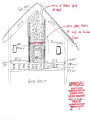
Plans must include a floor plan, a concrete footing and foundation plan, elevations all sides with
I
decks, balcony, steps, hand rails and guard rails, windows and doors, including the finish grade line
and original grade. A section showing in detail, from the bottom ofthe footing to the top of the roof,
including re-bar, anchor bolts, pressure treated plates, floor joists, wall studs and spacing, insulation,
sheeting, house-rap, (which is required), siding or any approved building material. Engineered
foundations ~ay be required.
A window schedule. A door schedule. A floor framing plan, a roof framing plan, roof must be
designed to withstand a 40 pound per square foot up to 7,000 feet in elevation, a 90 M.P.H. wind
speed, wind exposure B or C, and a 36 inch frost depth.
All sheets to be identified by number and indexed. All of the above requirements must be met or
your plans will be returned.
All plans submitted must be incompliance with the 2003 IRC.
1.
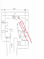
Is a site plan includ~d that identifies the location of the proposed structure or addition and
distances to the property lines from each comer of the proposed structure( s) prepared by
a licensed surveyor and has the surveyors signature and professional stamp on the
drawing? Properties with slopes of30% or greater must be shown on the site plan.
(NOTE Section: 1 06.2) Any site plan for the placement of any portion of a structure
within 50 ft. of a property line and not within a previously surveyed building envelope on
a subdivision final plat shall be prepared by a licen sed surveyor and have the surveyor' s
signature and professional stamp on the drawing. Any structure to be built within a
building envelope of a lot shown on a recorded subdivision plat shall include a copy of
the building env.e lope as it is shown on the final plat with the proposed structure located
within ~envelope.
Yes- - - -
2.
Does the site plan also include any other buildings on the prop erty, setback easements and
utility easements? Please refer to Section 5.05.03 in the Garfield County Zoning Resolution
if the property you are applying for a building permit on is located on a comer lot. Special
setbacks do apply.
Yes
,/
3.
Does the site plan include when applicable the location of the I.S.D.S. (Individual Sewage
Disposal System) and the distances to the property lines, wells (on subj ect property and
adjacent properties), streams or water courses?
Yes
4.
.
~ \fl.;
Does the site plan indicate the location and direction of the County or private road accessing
the property?
2
Yes
lv\r /
I
5.
Are you aware that prior to submittal of a building permit application you are required t.o
show proof of a driveway access permit or obtain a statement from the Garfield County Road
& Bridge Department stating one is not necessary? You can contact the Road & Bridge
Department at 625-8601.
Yes
/
6.
Do the plans include a foundation plan indicating the size, location and spacing of all
reinforcing s!eel in accordance with the IRC or per stamped engineered design?
Yes
}\-/_\.<
•
7.
Do the plans indicate the location and size of ventilation openings for under floor crawl
spaces and \the clearances required between wood and earth?
Yes
f'v _1
\ c::
8.
Do the p lans indicate the size and location of ventilation openings for the attic, roof j oist
~:sees an~s11ts?
9.
Do the plans include design loads as required by Garfie ld County for roof snow loads, (a
minimum of 40 p ounds per square foot up to & including 7,000 feet above sea level), floor
loads and : ind loads?
Yes
tJ1
I 0.
Does the plan include a building section drawing indicating foundation. wall. floor. and roof
construction?
Yes
11.
}.J
}v•(. . .
Does the building section drawing include size and spacing of floor joists, wall studs. ceiling
jo ists, roof ~afters or joists or trusses?
Yes
)J_t1
~ "
12.
Does the building section drawing or other detail include th e method of positive connection
of a ll co l~s and beams?
Yes
~1....
13.
Does the elevation plan indicate the height of the building or proposed addition from the
undisturbed grade to the midpoint between the ridge and eave of a gable or shed roof or the
top of a flav oof? (Building height measurement usua lly not to exceed 25 feet)
Yes
}'V ~
14.
Does the plan include any stove or zero clearance fireplace planned for installation including
3
15.
make and model and Colorado Phase II certifications or phase II EPA certification?
Yes
/
No _ _--=---:--:--:
Does the plan include a masonry fireplace including a fireplace section indicating design to
comply with the IRC?
~
No _ _ _ _ __
Yes
16.
Does the plan include a window schedule or other verification that egress/rescue windows
from sleeping rooms and/or basements/comply with the requirements of the IRC?
Yes
No
V
17.
Does the plan include a window schedule or other verification that windows provide natural
light and ventilation for all hab~re rooms?
Yes
No ______________
18.
Do the plans indicate the location of glazing subject to human impact such as glass doors,
glazing immediately adjacent to such doors; glazing adjacent to any surface normally used as
a walking surface; sliding glass doors; fixed glass panels; shower doors and tub enclosures
and specify safety glazing for these areas 0
Yes
No ____~--------
19.
Is the location of all natural and liquid petroleum gas furnaces, boilers and water heaters
indicated on the plan?
Yes
No _____________
20.
Do you understand that if you are building on a parcel of land created by the exemption
process or the subdivision process, ary· building plans in compliance with all plat notes
/
and/or covenants?
Yes
No- - - - - - - -
21.
Do you understand that if you belong to a Homeowners Association (HOA), it is your
responsibility to obtain written permission fi·om the association, if required by that
association, prior to submitting an application for a building permit? The building
permit application will be accepted without it, but you run the risk of the HOA bringing
action to enforce the covenants, which can result in revocation of permit issued.
Additionally, your Plan Review fee is not refundable if the plans have been reviewed by the
Building ~ep.~ent prior to any action by the HOA that requires either revocation or
substantia~uification of the plans.
Yes
No
J
------
22.
Will this be Jhe only residential structure on the parcel?
Yes
./
No
Uno-Explain: ______________
23.
Have two (2) complete sets of construction drawings been submitted with the application°
Yes___________
4
24 .
Do you understand that the minimum dimension a home can be on a lot is 20ft.wide and
20ft. long?
Yes
./
No
- - -- -
25.
Have you designed or had this plan designed while considering building a.nd other
construcB9ri code requirements?
Yes
No- - - - - -
26 .
Do your plans comply with all zoning rules and regulations in the County related to your
properties zone district?
Yes
f!\ll\-c> .c
No- - - - -- -
2 7.
Does the plan accurately indicate what you intend to construct and what will receive a final
inspection by the Garfield County Bui lding Department?
Yes
No- - - -- \ "---
trJ\a
28 .
Do you understand that approval for design and/or construction changes are required prior
to the aqBication of these changes?
Yes
/' )~
No_ __ _ __
29.
Do you understand that the Building Department will collect a "Plan Review" fee from you
at the time of application submittal and that you will be required to pay the "Permit Fee" as
well as any "Road Impact" or '' Septic System" fees required, at the time you pick up your
building permit?
Yes /V\A
No
\'="""
-
-----
30.
Are you aware that you must call in for an inspection by 3:30 th e business day before
the requested inspection in order to receive it the following business day? Inspections
will be made from 7:30a.m. to 3:30p.m. Monday through Friday. Inspections are to
be called in to 384-5003.
Yes
·, /
No
v
-----~
31.
Are you aware that requesting inspections on work that is not ready or not accessible will
result in a $50.00 re-inspection fee?
Yes
L/ "
No _ _ _ __
32.
Are you aware that you are required to call for all insp ections required under the IRC
including approval on a final inspection prior to receiving a Certificate of Occupancy and
occupancy ofjhe building?
Yes
~
No- - - ---;---
5
33.
Are you aware that the Permit Application must be signed by the Owner or a written
authority being given for an Agent and that the party responsible for the project must comply
~~~the~?
34.
No _____________
Do you understand that you will be required to hire a State of Colorado Licensed Electrician
and Plumber to perform installations and hookups, unless you · as the homeowner are
perfom1ing the work? The license number of the person performing the work will be
required at time of applicable inspection.
No______________
Yes
tv lo_
35 .
Are you aware, that on the front of the Building Permit Application you will need to fill in
the Parcel/Schedule Number for the lot you are applying for this permit on prior to submittal
of a building permit application? Your attention in this is appreciated.
~
No
Yes
------------------
36.
Do you know that the local fire district may require you to submit plans for their review of
fire safety issues? Yes
Jv
No
(please check with the
building department about this requirement)
3 7.
Do you understand that if you are planning on doing any excavating or grading to the
prope1ty prior to issuance of a building permit that you will be required to obtain a grading
pem1it?
~
Yes
JV p,.
38.
Are you aware that if you will be connecting to a public water and/or sewer system, that the
tap fees have to be paid and the connections inspected by the service provider prior to the
issuance of ~ Certificate of Occupancy?
Yes
• J
h,
Jv t:::
I hereby acknowledge that I have read, understand and answered these questions to the
#=y~~
St
ature of Owner
Phone:
2. t lf - d~ 8' (/
atb
<&fRY-
(days);
/
51
H?s
(evenings)
Project Name:___,3~V'--V\~V\'-l.-_~S.::..."'~0'--'-1':____.,:5;________________
Project Address:
3 Lj
R..: ve '( \?o&\.t
Pr · tve w ro..s 1--le r ' o ~I? c.; 7-
Notes: If you have answered "No" on any of the questions, you may be required to provide this
6
information at the request of the Building Official prior to beginning the plan review process.
Delays in issuing the permit are to be expected. Work may not proceed without the issuance of a
permit. If it is determined by the Building Official that additional information is necessary to review
the application and plans to determine minimum compliance with the adopted codes. the application
may be placed behind more recent applications for building permits in the review process and not
reviewed until required information has been provided and the application rotates again to first
position for review, delay in issuance of the permit or delay in proceeding with construction.
Bpminreq November2006
7
GARFIELD COUNTY
BUILDING REQUIREMENTS
Codes: 2003 IRC, IBC, IFGC, IMC, IPC,
Setbacks: Check subdivisions and zone district for setback requirements.
Snowload (measured at the roof): 40PSF up to 7000ft. elevation.
50PSF 7001 to 8000ft.
7 5PSF 8001 to 9000ft.
1OOPSF 9001 to 1OOOOft.
Seismic design category: B
Weathering probability for concrete: Severe
Termite infestation probability: None to slight
Wind speed: 90mph
Decay probability: None to slight
Wind Exposure: B or C (see section R301.2.1.4)
Frost Depth: 36in. to 8000ft. elevation. 42in. 8001 and above.
Winter Design Temperature: Minus 2 to 7000ft.; minus 16 over 7000ft.
elevation.
Air Freezing Index: 2500deg F-days to 7000ft.; over 7000ft. to be determined by
Building Official.
Ice shield under-layment required.
Mean Annual temp.: Variable
Insulation: Maximum glazing U factor: 0.50
Minimum R-Va1ues:
•
•
•
Ceilings/roofs R values are: R-30 stick built
structures. R-38log construction and steel
rafter construction.
Walls R values are R-19 wood frame; R-19
cavity R-3 sheathing steel studs.
Floors R-values are R-19.
•
•
•
Basement wall R-values are R-10 bel'ow
grade, R-19 above grade.
Slab perimeter R-value and depth is R10/36in.
Crawl space wall R-values are R-10 below
grade and R-19 above grade
If floors over crawl spaces are not insulated, the crawl space walls must be
insulated. Basement wall must he insulated to frost depth. Common walls
garage to house must have R-19 insulation. Common ceiling/floor garage
to house must have R-19. Take precautions to protect plumbing in these
areas.
PLAN REVIEW CHECKLIST
Applicant
:=':o \
1
'"")
Building
Date
) () -
J ( - 6
7
Planning/Zoning
~Engineered Foundation
Line Setbacks
/~Driveway Permit
--;_Surveyed Site Plan
Septic Permit and Setbacks
-----1,...----Gradeffopography 30%
~ttach Residential Plan Review List
~Minimum Application Questionnaire
~Subdivision Plat Notes
_&Fire Depattment Review
_ _ Planning Issues
l /luation Determination/Fees
_ _ Subdivision Plat Notes
_ _Red Line Plans/Stamps/Sticker
W
L Attach Conditions
~pplication Signed
-l.,.L.Plan Reviewer To Sign Application
~Parcel/Schedule
4
Jv'--'
No.
40# Snow load Letter- Manf. Hms.
Soils Report
GENERAL NOTES:
No.
---+r.>..Lmo....t=-Y...t.___
Assessor's Parcel No.
d,\~">34'3-'30-0\-b
Date
I O=lQ-Ol-
BUILDING PER,T CARD
)
"5ll £1\Rrboaf- he \'\)\CQUle \\:\\,l'I'Df>VJC) ";:1.)~~\g~tot\b
SJU'::>, .\\lO.D
Address ?l1 lWPrboo\f:>r
~on~ Q(Sl\-"j\l\8"
Job Address
owner
1
ContractorOW&\
Setbacks:
W~
Front
bu{n\v-q
Address
(
Phone #
\
J
Rear _ _ _ _ _ R H · - - - - - LH _ _ _ _ _ Zoning - - - - -
~,r-e.plo.ce
INsPECTioNs
Weatherproofing ______________
Mechanical ________________
Soils T e s t - - - - - - - - - - - Footing------------Foundation ____________
Grout __________________
Electrical Rough ( S t a t e ) - - - - - - - - Eiectric!ll Fi,[lal LState) ________~~--Final /f-2.-CCOltCheckli&J (:f:unpleted? liM/(
Underground Plumbing------Rough Plumbing r---=---o7.,--.,----Framing II- lif-t:> ?/fh?1.
Insulation-------------Roofing------------------Drywall - - - - - - - - - - - - - - Gas P i p i n g - - - - - - - - - - - - -
Certificate
Occu.~p:a:n~cy~#~N\.!i:~=======
-
Date_
~=~~\}~~\~~~======
Date
Septic System
Final
Other _ _ _ _ _ _ _ _ _ _ _ _ _ ____
NOTES
(continue on back)
FINAL CHECKLIST
IIXTIRIOR
MECHANICAL ROOM
Address N o . - - - - - - - - - - - - Drainage _ _ _ _ _ _ _ _ _ _ _ _ __
Boiler _ _ _ _ _ _ _ _ _ _ __
Hot water _ _ _ _ _ _ _ _ _ __
Decks-support & clearance to wood - - - - - -
FA gll9/ollo _ _ _ _ _ _ _ _ __
Oecks·stalrs & r a l l s - - - - - - - - - - -
Floor drain _ _ _ _ _ _ _ _ __
Clearance _ _ _ _ _ _ _ _ _ __
Exterior locks - - - - ' - - - - - - - - Flashing around doors & windows---'-----
Air con. s y s t e m ' - - - - - - - - -
STAIRWAYS,
Headroom (6'6") - - - - - - - - - Railing & guardrails - - - - - - - - Width---L----------
Rise & r u n - - - - - - - - - - - KITCHEN
Clearance above g r i l l - - - - - - - - Exhaust fan _ _ _ _ _ _ _ _ _ __
Insect s c r e e n s - - - - - - - - - - - -
Hot water h e a t e r - - - - - - - - Combustion air _ _ _ _ _ _ _ __
INTIRIOR
Gas piping, valves _ _ _ _ _--'._ _
GARAGE
LPG D r a i n - - - - - - - - - -
Broiler exhaust (1 hr. c h a s e ) - - - - - BEDROOMS
Egress _ _ _ _ _ _ _ _ _ _ _ __
Fire wall separation _ _ _ _ _ _ _ _ _ __
FIREPLACE/STOVE
Clearance to combustiblesi _ _ _ _ __
Smoke d e t e c t o r - - - - - - - - - BATHROOMS
Terminatlon of chimney,_ _ _ _ _ __
Combustion air _ _ _ _ _ _ _ __
Exhaust f a n - - - - - - ' - - - - - Shatterproof glass _ _ _ _ _ _ _ __
Hearth (12" or 20" on s i d e s ) - - - - Glass doors _ _ _ _ _ _ _ _ __
OTHER
Service doors-Hi" m i n . - - - - - - - - - Door (20 min.) w/auto closer-Pie" min. _ _ _ _ __
Mech. equip. 18" above floor _ _ _ _ _ _ __
No opening Into sleeping a r e a ' - - - - - - - -
BASEMENT·CAAWL AREA
Access _ _ _ _ _ _ _ _ _ _ _ _ __
Certified by: _ _ _ _ _ _ _ _ __
Insulation-------------Headroom/Stairs, _ _ _ _ _ _ _ _ _ _ __
Ventllation - - - - - - - - - - - - -
REMARKS
INSPECTION WILL NOT BE MADE UNLESS
THIS CARD IS POSTED ON THE JOB
24 HOURS NOTICE REQUIRED FOR INSPECTIONS
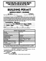
BUILDING PERMIT
GARFIELD COUNTY, COLORADO
.\.0~ . . . ..
}Q:l9:?.r.:. .
Date Issued .•
zoued Area ............................... Permit No....
AGREEMENT
Iu consideration of the issuance of this permit, the applicant hereby agrees to comply with all
laws and regulations related to the zoning, location; construction and erection of the proposed
structure for which this permit is granted, and further agrees that if the above said regulations
are not fully complied with in the zoning, location, erection and construction of the above
described structure, the permit may then be revoked by notice from the County Building
Inspector and IMMEDIATELY BECOME NULL AND VOID.
use
Wooo/IJIJIIIIWf H~eArte
Address or Legal Description
Owner
5:>L'S.
Setbacks
~"' J\ \1&1 be¥\tl \C- ~0W Cttlil\-le,
~\)QW\
Contractor
Front
Side
\))1\er
Sjde
Rear
This Card Must Be Posted So It is Plainly Visible From The Street Until Final Inspection.
INSPECTION RECORD
Driveway
Footing
Foundation
Underground Plumbing
Insulation
Rough Plumbing
Drywall
Chimney & Vent
Electric Final (by State Inspector)
Gas Piping
Final //- ;;zfr-0
Electric Rough (By State Inspector)
Septic Final
/1- 1,'f..~o1 ~
Framing
(To include Roof in place and indow
and Doors installed).
Notes:
7
/{j1Vf
ALL LISTED ITEMS MUST BE INSPECTED AND APPROVED BEFORE COVERINGWHETHER INTERIOR OR EXTERIOR, UNDERGROUND OR ABOVE GROUND.
THIS PERMIT IS NOT TRANSFERABLE
For Inspections Call 384-5003
l 08 8th Street
Glenwood Springs, Colorado
APPROVED DO NOT DESTROY THIS CARD
Date
f()-\Q·l
By
fjl[b
IF PLACED'OUTSJDE- COVER WITH CLEAR PLASTIC
Parcel Detail
Page 1 of 4
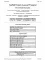
Garfield County Assessor/Treasurer
Parcel Detail Information
I
A~sfs_sQrlfr~1JsliJel· Propeity,<;emch
Assessor Subset ili!IT)'
Cl~rk. &Kec:.Qrl:l.erRec.:ep!ion Se<:lrch
Basic Building Characteristics
Parcel Detail
I
I TaxArea II
I
011
II
Assessor Sales Search
Tax Information
Sales Detail
Land Detail
I
I
Account Number
II
Parcel Number
II
Mill Levy
I
Rl70404
II
212334330016
II
38.984
I
Value Detail
I
I
I
Residential/Commercial Improvement Detail
Photographs
Owner Name and Mailing Address
lsANCHES, JUAN LUIS SOLIS &
lsoLIS, CORALIE DEL CARMEN
134 RIVERBOAT DRIVE
INEW CASTLE, co 81647
Legal Description
lsECT,TWN,RNG:34-5-90 SUB:RIVERBEND
lsUB-DIV FLG 5 LOT:16 PRE:ROI7026
IBK:l046 PG:0539 BK:0960 PG:0266
IBK:0958 PG:0275 BK:0952 PG:0742
IBK:0777 PG:0742 BK:0772 PG:0729
IBK:0549 PG:0172 BK:l919 PG:0102
IRECPT:722000 BK: 1815 PG:934
IRECPT:701201 BK:1386 PG:38
IRECPT:610589 BK:l048 PG:0636
Location
I
Physical Address: 1134 RIVERBOAT DR NEW CASTLE!
I
Subdivision: IIRIVERBEND SUB-DIV FLG 5
I
I
Land Acres: 110.338
II
I
http://www.garcoact.com/assessor/parcel.asp?Parce1Number=212334330016
10/18/2007
Page 2 of 4
Parcel Detail
Land Sq Ft: 1114,716
II
II
Section
34
Township
5
I
II
Range
90
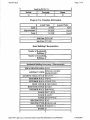
Property Tax Valuation Information
II
Actual Value
Assessed Value
I
6,8501
I
Land:
II
86,oooll
I
Improvements:
246,3ooll
19,6101
I
Total:
332,3ooll
26,4601
Sale Date: 114/25/2007
Sale Price: 11372,900
Basic Building Characteristics
Number of Residential
Buildings: 11
Number of Comm!lnd
Buildings: lo
Residential Building Occurrence 1 Characteristics
I
I
I
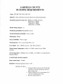
TOTAL HEATED AREA: 112,295
ABSTRACT CODE·IISINGLE FAM.RES' IMPROVEMTS
ARCHITECTURAL STYLE: IIBI LEVEL
EXTERIOR WALL: IIVINYL
EXTERIOR WALL: IISTONE VEN
ROOF COVER: llcOMP SHNGL
ROOF STRUCTURE: IIGABLE
INTERIOR WALL: IIDRYWALL
FLOOR: llsHT VINYL
FLOOR: llcARPET
FLOOR: IIHARDWOOD
HEATING FUEL: IlGAS
HEATING TYPE: IIFORCED AIR
STORIES: llsTORIES 1.0
I
I
BATHS: 13
http://www. garcoact.com/assessor/parcel.asp ?ParcelN umber=2123 343 300 16
10118/2007
Parcel Detail
Page 3 of 4
I
I
I
ROOMS: 16
UNITS: 11
BEDROOMS: 14
YEAR BUILT: 112002
I
I
Tax Information
I
I
I
I
I
I
I
I
I
I
I
I
I
I
I
I
I
I
I
I
I
I
I
I
Tax Year
2006
2006
2005
2005
I
I
I
I
I
Transaction Type
I
Tax Payment: Whole
II
($801.52)1
Tax Amount
I
$801.521
Tax Payment: Second Half
II
($401.07)1
Tax Payment: First Half
I
($401.07)1
Tax Amount
II
II
II
II
I
II
II
II
I
II
$802.141
Amount
I
Tax Payment: Second Half
2004
II
II
I
2004
II
Tax Amount
2003
Tax Payment: Second Half
2003
II
II
2003
II
Tax Amount
2002
I
II
Tax Payment: Second Half
2002
I
Tax Amount
2001
II
Tax Payment: Second Half
I
($318.99)1
2001
II
II
I
II
II
Tax Payment: First Half
II
I
II
($318.99)1
2005
2004
2002
2001
2000
2000
2000
1999
1999
1999
I
I
I
Tax Payment: First Half
Tax Pa~ment: First Half
Tax
Pa~ment:
First Half
Tax Amount
Tax Payment: Second Half
Tax
Pa~ment:
First Half
Tax Amount
Tax Payment: Second Half
Tax Pa~ment: First Half
Tax Amount
I
I
I
I
II
($471.04)1
($471.04)1
$942.081
($529.59)1
($529.59)1
$1,059.181
($336.52)1
($336.52)1
$673.041
$637.981
($239.68)1
($239.68)1
$479.361
($227.68)1
($227.68)1
$455.361
Top of Page
Ass(:ssor . D<ttal:Jas9 Sl':<m;hOptions
I
Tr9J15!!r~rJ><ttal:Ja~eSearcl!_Qp!ims
Clerk & Recorder Database Search Options
http://www. garcoact.com/ assessor/parcel. asp ?ParcelNumber=2123 343300 16
10/18/2007
___ D~\'( (.Jr(l~\.( S~~ e
fl• ' Jool~C\.tt.
Ct
<f'-e
r-
y? l"/w cJac)
.J c , s r
{J7f y WC/ f I
~----__.__..............,-.J-~-...,--f---.J._
APPROVE·u
SUBJECT TO NOTED
UCEP110NS & INSPECTIONS
GARFIELD COUNTY
BUILDING DEPARTMENT
Bide /O·J&-·o) By If~
FIELD CO
'NO JNSnCTION WITHOUT
'IW.Bft.ANSONS~
....
9t'
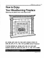
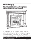
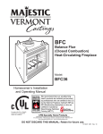
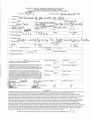
How to Enjoy
Your Woodburning Fireplace
Beaucoup de plaisir avec votre foyer
a bois
\1
J'
r-
J
=
~
/
1'\.
I
1)1
!=
1
L
I.
)
r-L
l '~.
~~
r
ll~
-~
Q
's..
...l.-
\,
r
BC, BCMH, BFC, BR, CR, CVR, EWF, ODSHR, ODSR, SC,
SHR, SR, STR, TF, TL, TSH, TST and WMC Series Fireplaces
FOYERS SERIES BC, BCMH, BFC, BR, CR, CVR, EWF,
ODSHR, ODSR, SC, SHR, SR, STR, TF, TL, TSH, TST et WMC
Save This Homeowner's Manual
Conservez ce manuel du proprietaire
20000706 2107 Rev. 11
Meet Your New Woodburning Fireplace
Your new fireplace is a highly engineered system
designed to provide maximum pleasure with troublefree operation. It can only perform to its fullest potential
if you operate and care for it properly. This manual is
provided to help you do that.
The first things you should know are the basic parts
of your particular fireplace model and what each part
does. This will give you a better understanding of the
descriptions that follow in this manual. It is important
to note that all of these parts have been engineered
to work together. If you decide to use some unapproved part or make any modification, the fireplace
will not operate as it was engineered to and, therefore, may possibly cause a fire hazard.
CFM Corporation warranty will be voided by, and
CFM Corporation disclaims any responsibility for
the following actions:
• Installation of any damaged fireplace or chimney
component;
• Modification of the fireplace, chimney assembly
or any of the component parts thereof; (except
for chase flashings as detailed in CFM Corporation
Chimney Top installation instructions).
Installation other than as instructed by CFM Corporation
or
• Installation and/or use of any component part not
manufactured or approved by CFM Corporation in
combination or assembly with a CFM Corporation
fireplace system, notwithstanding any independent testing laboratory or other third party approval of such component parts or accessory.
Any of the above actions may possibly cause a fire
hazard.
h.
WARNING
. . Risk of fire! Do not install a firescreen on
this prefabricated fireplace. A firescreen
will prevent proper ventilation and increase
the risk of a chimney fire.
NOTE: Remove the warranty card from the plastic bag in which you found this owner's manual.
The warranty for your fireplace is located on the
back page of the installation instructions. Keep the
warranty in a safe place for future reference if you
should ever need service covered under this warranty. Fill out the warranty card and mail it to CFM
Corporation. In order to validate your warranty, it is
mandatory that you write the serialization number
(a series of letters and numbers located below the
model number) on the warranty card. The serial
number is stamped into the black plate attached to
the inner dome side of the firebox.
For better understanding of your fireplace, familiarize
yourself with the following parts and terminologies used
in this manual:
The firebox is the main cavity of the fireplace where
the fire is built. Its shape and size are designed to
promote efficient burning of the fire and to reflect the
maximum amount of heat through the fireplace opening
into the room.
The hearth is the floor of the firebox. It is made of a
refractory material and functions as a base for the fire
grate to rest on.
The chimney is the complete vertical structure that
houses the flue. With CFM Corporation fireplaces, the
chimney utilizes a special air-cooled design that keeps
the outside of the chimney from getting too hot.
The flue is the innermost passageway of the chimney
system through which the smoke and gases from the
fire travel to the out-of-doors.
The damper is the door to the flue that prevents loss
of heated room air from escaping up the flue when
the fireplace is not in use. The damper must be in the
open position whenever fire is burning so that smoke
and gases can escape up the flue rather than into the
room. It should not be closed until the fire is completely
out. The BR, BC, BCMH, TF, TL, CR, SR, ODSR, SC,
SHR, ODSHR, TSH, STR, TST, CVR and EWF Series
fireplace damper operates only in the full open or full
closed position. The control is located in the front firebox dome areas. (Figs. 1, 2, 3, 4 & 5)
The EWF damper is open to start or revive the fire and
closed, for normal operation and to control burn rate.
NOTE: Always open the damper before opening the
doors. Close damper to set burn rate.
The WMC Series fireplace damper is adjustable to help
provide a more efficient fireplace operation. Dampering
down the open flue further intensifies the firebox heat
exchanger temperature by reducing the loss of hot flue
gases. The adjustable damper control is located in the
center just below the top outlet grille. (Fig. 1) Refer to
Proper Operating Procedure on Page 4.
20000706
3
during its installation. Fans are standard equipment for
WMC and BFC units.
NOTE: CFM Corporation Forced Air Systems are
designed to distribute heat at a specific cfm rate.
Any attempt to increase air movement through the
heat exchanger will decrease the heat transfer time
which will result in cooler heat circulation tempera·
tures.
Energy efficient options such as glass doors and fans
(Heat-circulating models) can easily be added after
your original fireplace installation. Refer to Page 11 for
description and proper model number.
n
'_.;CLOSED
I
AI
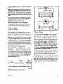
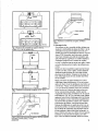
1. Open Flue Damper
The flue damper is meant to be closed only when the
fire is completely out and the fireplace is not in use.
This prevents the loss of room air up the open flue. Re·
member, the damper must always be in the "fully open"
position when a fire is burning.
WMC Damper: The WMC Series fireplace flue damper
is "opened" and "closed" by a knob located just below
the top outlet grille. (Fig. 1) The damper is adjustable
and may be adjusted to a partially open position as
long as the glass doors are closed and smoke buildup
does not occur in the firebox. Most efficient operation is
obtained in the least open position. When refueling, fully
open damper before opening glass doors.
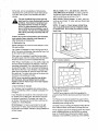
BR, BC, BCMH, TF, TL, CR, SR, ODSR and SC Se·
ries Damper: The flue damper is located in the dome
area in the middle of the firebox. The damper is opened
by rotating the lever to the right. The damper is closed
by pushing the lever to the left and is locked closed by
the damper clip located on the dome. The damper is
not adjustable and must only be operated in the
fully open position. (Fig. 2)
CLOSED
1:··
.......
.. -.... -""
PARTIALLY
OPEN
...........
----- 1-----""n
I
I
·---
...
FULLY
OPEN
I
II
I
I
I
-;]
v
T
v
n
How to Operate Your Fireplace
Your fireplace can provide countless hours of pleasure
and security. However, use your fireplace carefully
because any time you build a fire inside a house, a
problem may develop.
n
H
'
n
H
.!,.,_
~~
OPEN~
I
AI
=v
I
I
I
I
II
I
T
AI
·v=
MD706-2
F1g. 2 BR, BC, BCMH, TF, TL, CR, SR, ODSR & SC Senes
damper control positions.
STR, TST & CVR Series Damper: The flue damper
is located in the dome area in the middle of the fire·
box. The damper is opened by pushing the lever in an
upward direction. The damper is closed by pulling the
lever down toward the hearth brick at the bottom of the
fireplace. The damper js not adjystable and must
only be operated jn the fully ooen posjtjon. (Fig. 3)
SHR, ODSHR & TSH Series Damper: The flue damp·
er is "opened" and "closed" by an actuator handle and
linkage located in the front of the combustion dome of
the fireplace. The damper is not adjustable and must
be operated jn the fully open Position. (Figs. 4 & 5)
EWF Series Damper: The flue damper control is local·
ed in the upper right corner of the fireplace. The damper
is open when the lever is rotated clockwise and pulled
out on the EWF36A and pulled out on the EWF30.
Open the damper to start or revive a fire. The damper is
closed when pushed in. For the EWF36A only, when the
damper is in the open position, with the lever pulled out,
and rotated in the fully clockwise direction, the handle
can 'telescope' back without closing the damper or any
damper movement. There are no intermediate settings
for the damper.
OPEN DAMPER BEFORE CLOSING DOORS
M0706·1
F1g. 1 WMC Senes damper control posJtJons.
20000706
5
Soft woods, are not as desirable as hardwoods because they burn quickly and can cause resin build up
in the flue. Wet or green wood smolders and often
smokes.
A
The use of artificial logs of any type has
been found to create smoking and sooting
problems. These types of materials have
also been found to increase the danger
of fire. For these reasons the use of any
type of artificial log is prohibited in any of
our products. The use of any artificial logs
will void any warranty associated with our
products.
BR, BC, BCMH, TF, TL, SR, ODSR, SC, STR, TST,
CVR, WMC Series Air Damper. To 'open', push the
control lever down toward the hearth brick. To 'close',
pull the control lever up and over. (Fig. 7)
SHR, ODSHR, TSH Air Damper. To 'open', push control lever up and back. To 'close', pull lever forward and
down. (Fig. 8)
NOTE: To 'open' or 'close' damper during firing,
use a long metal probe such as a fireplace poker
to operate lever. Do not use your hand as control
lever is hot.
Caution: Do not burn scrap lumber, pine branches,
trash, plastic, flame colorants, soot cleaners or
other chemicals or compounds.
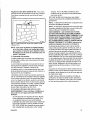
3. Starting the Fire
Before starting the fire, make sure the damper is in the
fully open position.
Lay a sheet of newspaper on top of the logs and set it
afire. This warms the chimney, improving the flow of hot
air from the fire when it is started.
When warm-up newspaper is partially burned, ignite
the starter paper under the kindling. Close the fireplace
screens as soon as you have completed this step.
FP710
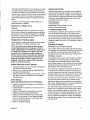
Fig. 7 Outside air operation.
When firing a new fireplace, you may smell a slight odor
and see smoke coming from the fireplace or the heatcirculating outlet grilles. This is the paint curing and oil
burning off the metal. This is normal and will disappear
after the f1rst few fires. If your fireplace is equipped with
glass doors and outside air, open the doors and close
the outside air. The odors and smoke will be drawn into
the firebox and expelled up the flue.
l
DOD
Your fireplace may be equipped with outside combustion air. To determine, refer to "Outside Combustion Air"
on Page 3.
If your fireplace has outside air, the air damper should
be 'closed' prior to starting fire. Start the fire and allow
the firebox to preheat 5-10 minutes, then 'open' the
air damper. The heat from the hot firebox will draw the
outside air in more effectively.
CRAir Damper. To 'open', push control rod to right
and pull out. To 'close', push control lever away from
the front face until it stops. Damper is spring-loaded and
will hold closed.
20000706
WcP
~}::tc;P
0
NOTE: Never use gasoline, gasoline type lantern
fuel, kerosene, charcoal lighter fluid or similar
liquids to start or 'freshen up' a fire in this fireplace
while it is in use.
4. Open Outside Air Damper
~
r.Open
Closed~
-
.~r::::L~--
-
' \I
FP710a
F1g. 8 SHR & TSH Senes outs1de a1r operatron.
5. Primary Air Control
The EWF has a single air control that regulates the
amount of heat the fire will produce and how long it will
burn.
The Primary Air Control is located in the upper left corner of the unit. It is the primary source of air for starting,
maintaining and reviving the fire.
Generally, more air entering the fireplace makes the fire
burn hotter and faster, while less air prolongs the burn.
The air supply is open to the maximum when the control
lever is rotated clockwise on the EWF36A or pushed
down on the EWF30 and closed when rotated counterclockwise on the EWF36Aor pushed up on the EWF30.
7
Please note that under moderate firing, some discoloration may occur on brass door frames. Keeping the fire
small and toward the back of the fireplace will prevent
this discoloration.
7. Operating Fan
If your fireplace is heat-circulating with a fan option,
build the fire in the normal manner with the fan(s) 'OFF'.
Preheat your firebox and heat exchanger system for 20
- 30 minutes. After a good fire has developed, turn the
fan switch to the 'ON' position and heated air will immediately fiow from the grille.
8. Tending the Fire
The heat output of a fireplace depends on how well
you build and tend the fire. A well-tended fire assures a
constant heat output. Keep the fire burning at a constant level by adding additional logs as necessary. Use
a poker to push the burning logs together into a tight
group at the back of the fireplace each time you add
new logs. Keep the bed of hot ashes located directly
under the logs. This aids in maintaining the fire, but do
not let the ashes get so deep that they interfere with
adequate air fiow up through the logs.
Except when adding logs to the fire, the firescreen
should always be kept closed whenever there is a fire
burning in the firebox.
9. Atthe End of the Day
If your fire has not burned itself out by bedtime, you
may wish to use your tongs to stand any burning logs
on end in the corners of the firebox. In this position,
they usually will quickly burn out and will provide good
base for your next fire. Be sure the firescreen or glass
doors are kept closed and the damper kept open until
the fire is completely out.
10. Disposal of Ashes
Clean the ashes from the firebox before starting each
fire. Ashes should be placed in a metal container with
a tight fitting lid. The closed container of ashes should
be placed on a noncombustible floor or on the ground,
well away from all combustible material, pending final
disposal. If the ashes are disposed of by burial in soil
or otherwise locally dispersed, they should be retained
in the closed container until all cinders have thoroughly
cooled.
Leave only enough ashes to insulate the cold hearth so
the fire will start faster. Excessive ash levels will slow
the burning of your fire and cause your grate to burn out
quickly.
11. Operation of BFC36, Clean-Burning Fireplace
The BFC36 fireplaces have been designed specifically
to reduce smoke and hydrocarbon emissions; however,
20000706
the performance of these fireplaces depends on proper
operation. In order to reduce emissions use only well
seasoned firewood. Avoid slow burning smoldering
fires and maintain a hot coal bed on which to place new
wood.
High firebox temeratures help to ensure effective operation of these clean-burning models.
The BFC36 clean-burning fireplaces must be burned
with the cabinet doors fully closed in order to reduce
emissions. Any modifications to the internal components of these fireplaces will likely cause an increase in
emissions. Always use the correct model grate and do
not remove any brick components, baffies or hardware
from the firebox.
12. Operation of EWF36A fireplace.
The EWF36A meets the US Environmental Protection
Agency's emission limts for wood heaters sold after
July 1, 1990.
The catalytic combustion system in your EWF produces
the best conditions for secondary combustion.
When the stove damper is closed, smoke goes through
the catalytic element, burning at temperatures of
500-600'F (260-315'C), half the temperature normally
needed for unaided secondary combustion.
The catalytic element is a ceramic "honeycomb" coated
with a noble metal, usually platinum. The element is in
the secondary combustion chamber, made of a special high-temperature insulating refractory material.
The chamber provides the correct environment necessary for secondary combustion of the fuel (smoke).
Closing the damper may also reduce draft. Closing
the damper too soon may put out the fire or deactivate
the combustor. Close the damper only when the fire is
well established. When starting a fire, wait until there is
an ember bed of at least 3-4 inches before closing the
damper.
13. Operation of EWF30
The EWF30 meets the US Environmental Protection
Agency's emission limits for wood heaters sold after
July 1, 1990.
The non-catalytic combustion system produces the
proper conditions for secondary combustion.
When the damper is closed, smoke goes through the
refractory combustion chamber at the back of the until.
Inside this chamber is where the secondary combustion
occurs.
Like the EWF36A, closing the damper too quickly is
detrimental to secondary combustion. When starting a
fire, wait until there is an ember bed of at least 3"- 4"
(76-1 02 mm) before closing the damper.
9
The hearth and firebrick liner of your fireplace are made
of a special fireclay material. While it is quite sturdy, it
can become cracked by normal expansion and contraction from heat or abuse. If hairline cracks should develop
in the hearth or firebrick liner, they can be ignored as
they will NOT affect the operation or safety of your fireplace.
Replacement Parts
Replacement parts for your fireplace can be obtained
from your CFM Corporation Dealer. For information on
replacement parts that are available, refer to installation
and homeowner's manual provided with each accessory.
Should you need additional information beyond what
your dealer can furnish, contact:
Contact your CFM Corporation Dealer if repair or replacement parts are needed.
CFM Corporation
410 Admiral Blvd.
Mississauga, Ontario Canada L5T 2N6
Attention: Technical Services
Maintenance of Glass Doors
Cleaning
Smoke residue may build up on glass doors over time.
Doors may be cleaned as necessary using nonabrasive
glass cleaners. Use of abrasive cleaners may damage
the surface of the glass and cause breakage. Never attempt to clean glass panels while hot.
Replacement of broken glass
Never operate a fireplace with cracked or broken glass
panels. Replace any damaged parts before use.
NOTE: Since the ceramic glass on these models
is quite fragile and proper mounting is critical for
safety, damaged glass on the BFC36 models should
be replaced by installing a new glass in the door
assembly. Do not attempt to install new glass in
the door frames. Remove the entire door assembly
by removing the four (4) screws securing the door
hinges to the fireplace. Replace with a new door
assembly. Contact your nearest CFM Corporation
Dealer for replacement parts.
Before Each Use of the Fireplace
1. Inspect the firebox to be sure it is clean and ready for
use. Remove excessive ashes.
2. Make sure your firescreen and air inleVoutlet grilles
are clean and unobstructed.
3. Inspect the hearth and firebox liner for cracks or damage. Make sure flue is unobstructed and damper is
completely open.
In the Spring After Last Seasonal Use of the Fireplace
1. Inspect the chimney top housing, removing any foreign obstructions.
2. Inspect the flue for obstructions and remove them if
any are found.
3. Inspect completely the chimney top for corrosion,
replacing any structurally weakened parts.
4. Inspect the chimney flashing. This is the first place
to look if you are having any roof leakage problem.
Check for ruptured areas such as nail heads and
seams. Seal any area found.
5. Clean the complete fireplace.
20000706
Troubleshooting Guide
Your fireplace is designed, safety tested and manufactured for trouble-free operation. Due to atmosphere,
home environment and improper operating procedures,
you may encounter the following common situation(s)
that you can remedy yourself. If your situation cannot be
corrected, contact your local CFM Corporation Dealer for
assistance.
Smoking Problems
Smoking occurs when fire is started
Your chimney and flue are probably cold. Place a piece
of newspaper on the top log and start burning just before
you start your crumpled up paper and kindling. This
newspaper will burn rapidly, warming up the ftue faster.
Smoking is constant
Your damper may be closed. Check damper and make
sure damper is in the open position. If your fireplace
is equipped with an adjustable damper, WMC Series,
check damper setting. In some cases, the lowest damper
setting will reduce the ftue draft and smoking will occur.
Open damper until smoke discontinues.
You may have an obstruction in your ftue or debris in or
on chimney top. Check for obstruction and remove. If
you fail to inspect your chimney ftue as recommended,
creosote buildup may have reduce.d the flue area. Check
chimney flue as described in maintenance procedure.
Your fire may be too far forward in the firebox. Push your
fire toward the back of firebox with a suitable tool If a
basket grate larger than the supplied or recommended
size is used, smoking would occur. Replace basket grate
with model specified and listed on Page 11.
You may not be using a grate to keep your fire up off the
hearth. This is important to get the proper draft. Let the
fire die out and rebuild per previous instructions. Your
chimney top may not be high enough above your roof. It
may be necessary to increase the height of your chimney top. Contact your dealer for chimney top extension
and other parts needed. See your chimney top installation instructions.
11
Accessories for Woodburning Fireplaces
The following accessory parts can be obtained from your CFM Corporation Dealer. Should you need additional information, beyond
what the dealer can furnish, contact CFM Corporation 410 Admiral Blvd., Mississauga, Ontario, Canada L5T 2N6 Attention: Technical Services.
Woodburning
Outside
Models
Air
Fan
Kit
BC36, BC36i,
BC36MH,
TL36, TL36i
AK-MST
FK12
BR36, BR36i
TF36, TF36i
AK-MST
N/A
BC42, BC42i
TL42, TL42i
AK-MST
FK12
BR42, BR42i
TF42, TF42i
AK-MST
N/A
SC36A
AK-MST
FK12
SR36A
AK-MST
N/A
AKU1
N/A
SC42A
AK-MST
FK12
SR42A
AK-MST
N/A
AKU1
N/A
STR33
AK-MST
N/A
STR36, CVR36
AK-MST
N/A
ODSR36A
ODSR42A
Glass Door
Kit
36GDKBB
36GDKBK
36GDKDP
36GDKS
36GDKBB
36GDKBK
36GDKDP
36GDKS
42GDKBB
42GDKBK
42GDKDP
42GDKS
42GDKBB
42GDKBK
42GDKDP
42GDKS
36GDKBBSR
36GDKBKSR
36GDKDPSR
36GDKSSR
36GDKBBSR
36GDKBKSR
36GDKDPSR
36GDKSSR
36GDKBBSR
36GDKBKSR
36GDKDBSR
36GDKSSR
36GDKSSSR
42GDKBBSR
42GDKBKSR
42GDKDPSR
42GDKSSR
42GDKBBSR
42GDKBKSR
42GDKDPSR
42GDKSSR
42GDKBBSR
42GDKBKSR
42GDKDBSR
42GDKSSR
42GDKSSSR
33GDKBB
33GDKBK
33GDKDP
33GDKS
36GDKBB
36GDKBK
36GDKDP
36GDKS
Chimney
System
Flue
Basket
Dia.
Grate
SK8 or S
8"
3030129
SK8 or S
8"
3030129
SK8 or S
8"
3030129
SK8 or S
8"
3030129
SK8 or S
8"
3041130
SK8 or S
8"
3041130
SK8 or S
8"
20006701
SK8 or S
8"
3041130
SK8 or S
8"
3041130
SK8 or S
8"
20002230
SK8 only
8"
2056100
SK8 only
8"
2056100
'SK' 2-WALL SYSTEM W/11" O.D.
'CF' 2-WALL SYSTEM W/13-112" O.D.
'S' 3-WALL SYSTEM W/13-112" O.D.
20000706
13
Beaucoup de plaisir avec votre foyer a bois
;_/
\l
r·t·
~
u
10
-;;;;::
/
1'\
~
... -,
t:r; \
I
I
!
'
I
r.t_j
(
.J
L
J
- J. '
r-
·r
-~~~
m.
(il"
=
I
r ,
,.-I"'
.
I
-
~
IDI
"'
~
~
..1
"'
~r
FOYERS SERIES BC, BCMH, BFC, BR, CR, CVR, EWF,
ODSHR, ODSR, SC, SHR, SR, STR, TF, TL, TSH, TST et
WMC
20000706
15
juste en dessous de Ia grille de sortie du dessus. (Fig.
1) Reportez-vous a Ia procedure de fonctionnement
appropriee, page 4.
Le pare-etincelles est un ecran de protection sous
forme de grillage metallique qui empeche les etincelles et les braises chaudes de quitter Ia chambre de
combustion. Le pare-etincelles doit toujours etre terme
lorsqu'un feu brOie dans Ia chambre de combustion.
Votre foyer peut aussi comporter les composants d'efficacite energef1que suivants qui procurent une chaleur supplementaire et permettent un fonctionnement
efficace Ia maison :
a
La circulation de Ia chaleur s'ajoute au rayonnement
standard des foyers classiques en distribuant dans Ia
maison des quantites appreciables de chaleur par convection. Les foyers a circulation de chaleur font circuler
!'air froid de Ia piece autour de Ia chambre de combustion ou il est rechauffe; il est ensuite renvoye dans Ia
piece qui beneficie alors d'une chaleur supplementaire.
Les modeles de foyers des series HBC et HBCL posse·
dent cette circulation de chaleur.
a
L'echangeur de chaleur est un dispositif plusieurs
parois qui dirige !'air ambiant autour de Ia chambre de
combustion et le renvoie dans Ia piece ou se trouve Je
foyer a circulation de chaleur. Le transfer! de chaleur
entre le foyer et I' air ambiant en circulation s'effectue
grace ces voies de passage. L'echangeur de chaleur
est le cceur du systeme de circulation de Ia chaleur, qui
fournit une chaleur ambiante supplementaire perdue
dans les foyers classiques.
a
Les grilles d'admission et de refoulement de l'air
appartiennent au systeme de circulation de Ia chaleur.
L'air ambiant froid entre par Ia grille du fond etlou les
grilles laterales inferieures et circule dans les voies de
passage de l'echangeur de chaleur. L'air chaud obtenu
est en suite renvoye dans Ia piece par Ia grille de refoulement superieure.
NOTE : Les grilles d'admission et de refoulement
de I' air ne doivent jamais etre recouvertes ou
obstruees. Le systeme de circulation de Ia chaleur
sert a~ssi de systeme de refroidissement du toyer,
ce qUI rend plus securitaire le fonctionnement de
celui-ci.
Air de combustion exterieur: Un feu necessite une
quantile suffisante d'air pour bien brQier. Si Ia quantile
d'air est insuffisante, de Ia tumee, de Ia suie et des
gaz nocifs emis par le foyer s'infiltrent dans Ia piece.
Lorsque le feu brQie dans Ia chambre de combustion
!'air de remplacement de Ia piece entre par l'ouvertur~
de celle-ci et compense Ia perte de I' air de combustion.
II arrive souvent que des maisons scellees et bien isolees ne permettent pas a des quantites suffisantes d'air
d'entrer dans ce processus de remplacement nature!.
20000706
Pour maintenir un debit constant d'air de combustion il
faut de I' air exterieur direct.
'
Les foyers CFM Corporation son! con9us pour que de
!'air exterieur puisse alimenter directement Ia chambre
de combustion en air de combustion. Le c.ircuit d'air
necessite Ia pose d'un conduit allan! du foyer a une
source d'air exterieur Iars de !'installation initiale. Les
foyers des series WMC, BR, BC, BCMH, TF, TL, CR,
SC,SHR,ODSHR,TSH,SR,ODSR,STR,TSTetCVR
com portent ce disposif1f standard. Une source d'a'1r exterieur integree est comprise sur le foyer BFC et aucun
conduit supplementaire n'est necessaire.
Si votre toyer est muni d'une entree d'air exterieur, le
levier de commande se trouve sur le bard avant gauche des briques sur les foyers de Ia serie BR, TF, SR,
ODSR, WMC, STR et TST. Surles foyers de serie CR,
il se trouve en bas a gauche ou dans le coin droite
sur !'entree d'air. Pour les series SHR, ODSHR et TSH,
le levier de commande se trouve au centre, juste audessus dU cote gauche. Reportez-vous, page 6, pour
connaitre Ia procedure appropriee. Consultez Ia page 5
pour connaitre Ia procedure de fonctionnement.
a
Commande d'air primaire : Sur le foyer de serie EWF,
Ia commande d'air primaire permet de regler Ia chaleur que le feu produira et Ia dun)e de combustion. La
commande d'air primaire se trouve dans le coin en haul
a gauche de l'appareil. C'est Ia source principale d'air
pour demarrer, maintenir et attiser le feu.
L'admission d'air est ouverte au maximum quand le levier de commande est tourne dans le sens des aiguilles
d'une montre sur le EWF36A ou a appuye sur sur le
EWF30 et fermee quand il est tourne sur le EWF36A ou
a releve sur le EWF30 dans !'autre sens. Pour regler Ia
combustion, ajustez Ia commande dans Ia position desiree entre ces deux points; quand Ia commande d'air
primaire est ouverte, l'appareil chauffe plus. Quand elle
est fermee, il chauffe mains. Vous pouvez regler a Ia
position de votre choix.
Des partes en verre ameliorent l'efficacite du toyer
et permettent de conserver Ia chaleur de Ia maison.
Lorsqu'un feu brOie, !'air de Ia piece fournit l'air de
combustion necessaire a Ia chambre de combustion ou
il se melange avec les gaz de combustion chauds; le
melange est ensuite evacue par le conduit ouvert. La
perte de !'air ambiant chaud est plus importante lorsque
le feu est peu intense, ce qui se produit normalement a
l'allumage eta !'extinction du feu. Les partes en verre
CFM Corporation son! specialement con9ues pour
reduire Ia quantile d'air ambiant chaud perdu tout en
permettant a une quantile appropriee d'air de combustion de s'infiltrer dans Ia chambre de combustion pour
assurer un fonctionnement securitaire.
Lorsque des partes en verre son! utilisees sur un foyer
a circulation de chaleur, !'air de combustion contr61e
17
~
{\
-j'...J
{\
Ferme
\_ Registre
I
A•
I
I
I
A
·v
v
I
{\
Registre poignee
{\
H J... H
--..-r~
JFerme
Ouvert ~
ouvert
AI
AI
MD706-2
v
y
F1g. 2 Pos1t1ons de commande du reg1stre. (BR, BC,
BCMH, TF, TL, CR, SR, ODSR & SC)
n
n
IIE'3Il
.
Ferme
...
.lL.
n
y
~~
\...
tll
n
v
t
Ouvert
MD706-9
Fig. 5 Positions de commande du registre. (SHR52 &
TSH52)
2. Allumage du.feu
Pour allumer un feu, une grille doit etre utilisee pour
soulever le combustible au-dessus de l'atre. L'air de
combustion doit pouvoir circuler travers le combustible pour que Ia combustion soil bonne. Tousles
foyers CFM Corporation son! livres avec une grille.
Votre foyer necessite une grille de conception speciale. Remplacez Ia grille par un modele specifique.
Consultez Ia page 9 pour le numero de modele.
Le EWF ne dispose pas de panier avec grille. Preparer le feu directement sur Ia grille. Ne soulevez pas
le bois.
Mettez une bonne quantile de papier journal froisse
ou tordu sur l'atre, sous Ia grille. Laissez depasser
quelques bouts de papier de Ia zone des buches
pour pouvoir les allumer. Disposez sur le papier du
bois d'allumage (bouts de bois de faible diametre)
en les croisant.
Mettez une buche de grand diametre sur le bois
d'allumage approximativement 1/2 po de Ia paroi
arriere du foyer; choisir de preference une buche qui
a ete fendue. Placez une deuxieme buche fendue a
1 ou 2 po devant Ia premiere. Placez une troisieme
buche fen due sur le dessus des deux autres pour
former une pyramide grossiere. verifier que les
irregularites des buches permettent l'air de passer
entre celles-ci. (Fig. 4) Si ce n'est pas le cas, placez
quelques bouts de bois d'allumage entre les buches
pour les separer un peu. Des buches supplementalres peuvent eire ajoutees au besoin pour maintenir
Ia production de chaleur. Les buches doivent eire
fendues de preference en quarts de sections ou en
pieces plus petites. Les buches fendues possedent
des surfaces de combustion plus etendues que les
bOches entieres et elles brOient plus facilement. Le
type et !'eta! dubois que vous brulez ant une grande
incidence sur Ia production de chaleur par votre
foyer. Pour de meilleurs resultats, brulez du chene,
a
a
JL.
A
~I
MD706-3
F1g. 3 Pos1t1ons de commande du reg1stre. (STR, TST &
CVR)
a
1Registre
oCommande
cdu registre
I
Fig. 4 Positions de commande du registre. (SHR36, SHR42A,
ODSHR42, SHR48,TSH36, TSH42)
20000706
19
Registre de serie SHR, ODSHR et TSH : Pour ouvrir,
poussez le levier de commande vers le haul et l'arriere.
Pour fermer, poussez le levier vers le bas et l'avant.
(Fig. 8)
r.;Ou~rt
,/..,
Ferme ~~
DOl
oocep
DDc:J~:::J
-
PSQP
FP710a
F1g. 8 FonctJonnement de l arnvee d a1r extlmeur. (SHR,
ODSHR, TSH)
NOTE : Pour ouvrir ou fermer un registre pendant
qu'un feu brule, utilisez una longue tige metalli·
que, comma un tisonnier, pour deplacer le levier.
Ne deplacez pas le levier de commande avec vos
mains, il est chaud.
5. Commande d'air primaire
Le EWF possede une commande d'air unique qui per·
met de regler Ia chaleur que le feu produira et Ia duree
de combustion.
La commande d'air primaire se trouve dans le coin en
haul a gauche de l'appareil. C'est Ia source principale
d'air pour demarrer, maintenir et attiser le feu.
En general, plus il y a d'air passant dans le foyer, plus
le feu est chaud et le bois se consume vile, moins il y a
d'air, plus le feu dure longtemps.
L'admission d'air est ouverte au maximum quand le levier de commande est tourne dans le sens des aiguilles
d'une montre et fermee quand il est tourne dans l'autre
sens. Pour regler Ia combustion, ajustez Ia commande
dans Ia position desiree entre ces deux points; quand Ia
commande d'air primaire est ouverte, l'appareil chauffe
plus. Quand elle est fermee, il chauffe moins. Vous
pouvez regler Ia position de votre choix.
6. Ouverture et fermeture des portes en verre
AVERTISSEMENT : Pour votre foyer, n'utilisez que
des portes en verre approuvees par CFM Home
Products.
Si votre foyer est muni de portes en verre, allumez
le feu et laissez-les completement ouvertes. Pour
un rendement maximum, nous recommandons
l'utilisation de partes vitrees sur to us les modeles de
foyer CFM Corporation, sauf les modeles de serie
BFC, EWF et WMC pour lesquels les partes doivent
etre completement ouvertes pour un feu modere
a
chaud. Pour un feu faible a modere ou pour
I' extinction du feu, les portes doivent etre fermees.
Les foyers de serie
BFC, EWF et WMC sont con9us pour une chaleur
maximum avec les portes completement fermees en
permanence.
NOTE : Le foyer BFC doit fonctionner uniquement avec
les portes completement fermees.
NOTE : Le foyer EWF doit fonctionner uniquement avec
les portes completement fermees ou avec un pare-etincelles si elles sont completement ouvertes.
AVERTISSEMENT: LES PORTES DES FOYERS
EN FONCTION DOIVENT ETRE COMPLETEMENT
OUVERTES OU COMPLETEMENT FERMEES. Sl LES
PORTES SONT PARTIELLEMENT OUVERTES, DES
GAZ ET DES FLAMMES PEUVENT S'ECHAPPER
DE L'OUVERTURE DU FOYER ET CONSTITUER UN
RISQUE D'INCENDIE ET DE FUME E. Examinez les
positions adequates des portes sur Ia figure 4.
Ne fermez pas les partes en verre si le feu est Ires
chaud. Cela pourrait supprimer Ia trempe du verre, et
les partes pourraient se briser en petits morceaux. Le
verre doit pouvoir se rechauffer lentement. Le verre
trempe des partes supporte une augmentation de temperature graduelle jusqu'a 550°F, ce qui est une temperature superieure ace qu'un feu normal peut atteindre.
Un feu excessivement chaud peut etre dO des bOches
chargees de goudron, des bouts de bois de sciage
Ires sees ou des grandes quantites de papier ou de
carton ondule. Maintenez le feu loin des portes et ne
laissez jamais les flammes entrer en contact aVE!C le
a
a
a
verre.
Les partes en verre peuvent se briser si elles sont mal
utilisees. Faites toujours attention lorsque vous ouvrez
les partes; ne les claquez pas et ne les forcez pas pour
les mettre leur place.
Veuillez noter que dans des conditions normales de
combustion, les cadres de porte en laiton peuvent se
decolorer un peu. Maintenir le feu petit et vers l'arriere
du foyer peut permettre d'eviter cette decoloration.
a
a
20000706
21
elles doivent etre conservees dans le recipient hermetique jusqu'a ce que toutes les escarbilles scient
completement refroidies.
Laissez suffisamment de cendres pour isoler l'atre
froid afin de faire demarrer le feu plus rapidement.
Une trop grande quantile de cendres ralentit Ia combustion de votre feu et fait brOier plus rapidement
votre grille.
11. Fonctionnement du BFC36, foyer combustion
propre
a
Les foyers BFC36 sent specialement conyus pour
nlduire Ia formation de Ia fumee et des hydrocarbures;
cependant, le rendement de ces foyers est directement
lie une utilisation appropriee. Pour reduire les emissions, utilisez uniquement du bois bien sec. Evrtez les
feux couvants combustion lente et maintenez une
couche de braises sur laquelle placer de nouvelles
bOches.
Les temperatures elevees de l'aire de combustion permettent d'obtenir un rendement efficace de ces modeles a combustion propre.
Les foyers a combustion propre BFC36 doivent fonctionner avec les partes de l'habillage completement
fermees, ceci afin de reduire les emissions. Toutes
modifications apportees aux composants internes de
ces foyers risquent de provoquer une augmentation des
emissions. Utilisez toujours Ia grille du modele approprie et ne retirez pas les composants en brique, les
defiecteurs ou le materiel de l'aire de combustion.
12. Fonctionnement du foyer EWF36.
Le foyer EWF36A repond aux normes d'emission
etablies par Ia US Environmental Protection Agency
concernant les appareils de chauffage a bois vendus
a pres le 1" juillet 1990.
Le systeme de combustion catalytique de votre EWF
produit les meilleures conditions pour une combustion
secondaire.
Lorsque le registre du poele est ferme, Ia fumee traverse !'element catalytique provoquant des temperatures
de 500-600°F (260-315°C), moitie moins elevees que
les temperatures normales pour Ia combustion secondaire naturelle.
L'element catalytique est une surface alveolaire en
ceramique recouverte d'un metal noble, habituellement
du platine. L'element se trouve dans Ia chambre de
combustion secondaire, fabriquee dans un materiau retractaire isolant special il haute temperature.
Lachambre procure l'environnement approprie requis
pour Ia combustion secondaire du combustible (fumee).
La fermeture du registre peut aussi reduire le tirage.
La termeture trop rapide du registre peut arreter le feu
ou desactiver Ia chambre de combustion. Fermez le
registre uniquement quand le feu est bien allume. Pour
allumer un feu, attendez qu'il y ail une couche de braise
a
a
20000706
d'au moins 3-4 pouces avant de fermer le registre.
13. Fonctionnement du EWF30
Le foyer EWF30 repond aux normes d'emission
etablies par Ia US Environmental Protection Agency
concernant les appareils de chauffage a bois vendus
apres le 1" juillet 1990.
Le systeme de combustion non catalytique produit les
conditions appropriees pour une combustion secondaire.
Quand le registre est ferme, Ia tumee passe par Ia
chambre de combustion en materiau refractaire
l'arriere de l'appareil. C'est dans cette chambre que Ia
combustion secondaire se produit.
Comme pour le EWF36, Ia fermeture trop rapide du
registre a un effet negatif sur Ia combustion secondaire.
Pour allumer un feu, attendez qu'il y ait une couche
de braise d'au moins 3-4 pouces avant de fermer le
registre.
a
Mesures de precaution
Bien que les mesures de precaution suivantes aient ete
presentees plus haul dans ce manuel, elles sent indiquees ici pour insister et fournir une reference rapide.
Mesures de precaution relatives au foyer
1. Verifiez que tous les passages du systeme de cheminee sont libres et sans obstruction.
2. Ouvrez toujours le registre avant d'allumer un feu et
laissez-le ouvert tant que le feu brOie. Ne fermez pas
le registre tant que le feu n'est pas completement
eteint.
3. Verifiez que le feu re('oit suffisamment d'air pour
eviler Ia fumee, Ia suie et Ia formation de gaz nocifs.
4. Utilisez toujours une grille pour supporter le feu. Si Ia
grille est brOiee, celle-ci doit etre remplacee par une
grille approuvee par CFM Home Products. Consultez
Ia page 19 pour connaltre les modeles de remplacement.
5. Ne brOiez jamais de rebuts de bois de sciage, de
branches de pin, de dechets, de plastique, de colorant de !Iamme, de nettoyeurs de suie ou d'autres
produits ou composants chimiques.
6. N'utilisez jamais de combustible liquide ou d'allumefeu liquide.
7. Construisez votre feu a1/2 po approximativement de
l'arriere de Ia chambre de combustion pour obtenir
une bonne combustion.
8. Faites toujours attention lorsque vous ajoutez du
bois au feu et lorsque vous utilisez vos outils de
foyer (pelle, pinces, tisonnier, etc.).
9. Les premiers feux doivent etre petits.
10. N'emballez pas votre foyer.
11. Fermez toujours votre pare-etincelles lorsqu'un feu
brOie.
23
Remplacement de verre brise
Guide de depannage
Ne faites jamais fonctionner un foyer avec des partes
de verre fissurees au cassees. Remplacez toutes les
pieces endommagees avant utilisation.
La securite de votre foyer a ete testee, et il a ete con9u
et fabrique pour fonctionner sans detaillance. En raison
de /'atmosphere, de l'environnement residential et de
techniques d'utilisation inappropriees, vous pouvez
rencontrer /es anomalies suivantes auxquelles vous
pouvez remedier vous-meme. Si l'anomalie ne peut pas
etre corrigee, communiquez avec votre detaillant CFM
Corporation local pour qu'il vous aide.
NOTE : La vitre ceramique sur ces modeles est fragile
et le montage est important pour Ia securite. Si Ia vitre
est endommagee sur les modeles BFC36, elle doit etre
remplacee en installant une nouvelle vitre dans Ia porte.
N'essayez pas d'installer une nouvelle vitre dans les
encadrements de Ia porte. Devissez /es quatre (4) vis
fixant /es charnieres au foyer et
retirez toute Ia porte. Remplacez par une nouvelle
porte. Contactez votre concessionnaire CFM Corporation pour les pieces de rechange.
Avant chaque utilisation du foyer
1. Verifiez que Ia chambre de combustion est propre et
prete a etre utilisee. Retirez l'exces de cendre.
2. Verifiez que le pare-etincelles et que les grilles d'admission et de refoulement d'air sont propres et sans
obstruction.
3. Verifiez si /'atre et Ia chemise de Ia chambre de combustion sont fissures ou endommages. Verifiez que
/e conduit n'est pas obstrue et que le registre est
completement ouvert.
Au printempsAvant Ia derniere utilisation saisonniere du foyer
1. Verifiez Ia tete de Ia cheminee et retirez tout corps
stranger.
2. Verifiez si le conduit est obstrue et retirez les corps
etrangers /e cas echeant.
3. Verifiez completement Ia tete de Ia cheminee pour
deceler toute corrosion; remplacez toutes les pieces
affaiblies structurellement.
4. lnspectez le so/in de cheminee. C'est le premier endroit qu'i/ taut regarder si vous avez des problemes
de fuite de toiture. Verifiez s'il y a des zones cassees, comme des tiites de claus et des soudures.
Scellez toute zone trouvee.
5. Nettoyez tout le foyer.
Pieces de rechange
Vous pouvez vous procurer des pieces de rechange
pour votre foyer aupres de votre detaillant CFM Corporation. Pour toute information sur les pieces de rechange disponibles, consultez /emanuel d'installation et du
proprietaire fourni avec chaque accessoire. Pour toute
information supp/ementaire depassant ce que votre
detaillant peut vous fournir, communiquez avec :
CFM Corporation
410Admiral Blvd.
Mississauga, Ontario
Canada L5T 2N6
ATT: Service Ia clientele
a
20000706
Problemes de fumee
II y a de Ia fumee
a l'allumage du feu
Votre cheminee et votre conduit sont probab/ement
froids. Mettez une feuille de journal sur les bOches et
allumez-la juste avant d'allumer le papier froisse et /e
bois d'allumage. Ce papier journal brule rapidement et
rechauffe plus vite /e conduit.
Le foyer fume constamment
Le registre peut etre ferme. Verifier que le registre est
en position ouverte. Ouvrez le registre jusqu'a Ia disparition de Ia fumee.
Le conduit peut etre obstrue; il peut aussi y avoir des
debris dans ou sur /e mitron de Ia cheminee. Verifiez
s'il y a des obstructions et retirez-les le cas echeant. Si
vous n'inspectez pas le conduit de cheminee de Ia fayon recommandee, une accumulation de creosote peut
avoir reduit son diametre. Verifiez le conduit de cheminee de Ia fayon decrite dans Ia procedure d'entretien.
a
Le feu peut etre trop /'avant de Ia chambre de combustion. Poussez /e feu vers l'arriere de Ia chambre de
combustion a /'aide d'un outil approprie. Si Ia grille est
plus grande que celle fournie par CFM Home Products
au superieure a Ia taille recommandee, le foyer peut fumer. Remplacez Ia grille par un modele specifie et liste
sur Ia page 19 des accessoires.
Vous n'utilisez peut etre pas de grille pour soulever le
feu au-dessus de l':itre. Cela est important pour obtenir
un bon tirage. Laissez le feu s'eteindre et reconstruisez-le conformement aux directives precedentes. La
tete de votre cheminee peut ne pas etre assez elevee
au-dessus du toit. II peut etre necessaire d'augmenter
Ia hauteur de Ia tete de votre cheminee. Communiquez
avec votre detaillant pour une extension de tete de cheminee et les autres pieces necessaires. Consultez les
directives d'installation de Ia tete de cheminee.
La fumee apparail un certain temps apres le debut
de Ia combustion
Lars de /'alimentation et de l'entretien du feu, celui-ci a
peut-etre ete avance dans Ia chambre de combustion.
Poussez le feu vers l'arriere de Ia chambre de combustion /'aide d'un outil approprie.
a
Si votre residence est hermetique et bien iso/ee, Ia
manque d'air de combustion peut provoquer de Ia
25
a
Si cet essai indique qu'il y a une anomalie, pensez
d'autres facteurs possibles, comme le temps ou un
changement de qualite de votre combustible. Par temps
chaud, le tirage est plus Iaible que par temps froid
hivernal, et Ia combustion peut etre ralentie. Des petits
feux intenses constituent une bonne solution dans ces
conditions.
Lorsque du bois vert (insuffisamment seche) est brQie,
le rendement est plus Iaible que lorsque le bois est bien
seche. Vous devez rechauffer un peu plus votre poele
(plus d'air) pour obtenir un bon rendement avec du bois
vert ou encore humide.
De plus, tenez compte des modifications de votre mode
de fonctionnement. Une lois que vous avez envisage
toutes les autres causes possibles d'une diminution du
rendement, verifiez et nettoyez Ia chambre de combustion.
Accessoires destines aux foyers
a bois
Les accessoires suivants peuvent etre obtenus chez votre detaillant CFM Corporation. Pour toute information supplementaire qui depasse ce que votre detaillant peut vous fournir, communiquez avec CFM Corporation, 410 Admiral
Blvd., Mississauga, Ontario Canada L5T 2N6, ATT : Service Ia clientele
a
Modeles
a
Bois
Air extErieur Necessaire de
ventilateur
BC36. BC36i,
BC36MH,
TL36, TL36i
AK-MST
FK12
BR36. BR36i
TF36. TF36i
AK-MST
S/0
BC42, BC42i
TL42. TL42i
AK-MST
FK12
BR42, BR42i
TF42. TF42i
AK-MST
S/0
SC36A
AK-MST
FK12
SR36A
AK-MST
S/0
SC42A
AK-MST
FK12
Necessaire de
porte en verre
36GDKBB
36GDKBK
36GDKDP
36GDKS
36GDKBB
36GDKBK
36GDKDP
36GDKS
42GDKBB
42GDKBK
42GDKDP
42GDKS
42GDKBB
42GDKBK
42GDKDP
42GDKS
36GDKBBSR
36GDKBKSR
36GDKDPSR
36GDKSSR
36GDKBBSR
36GDKBKSR
36GDKDPSR
42GDKBBSR
42GDKBKSR
42GDKDPSR
42GDKSSR
Systeme de
cheminee"'
Dia. Du conduit
Grille
SK8 or S
8 po
3030129
SK8 or S
8 po
3030129
SK8 or S
8 po
3030129
SK8 or S
8 po
3030129
SK8 or S
8 po
3041130
SK8 or S
8 po
3041130
SK8 or S
8 po
3041130
Systeme ADeux Parois SK Avec 11 Po De Dia. Ext6rieur
Systeme A Deux Parois CF Avec 131h Po De Dia. Exterieur
Systeme A Trois Parois S Avec 11h Po De Dia. Exterieur
20000706
27
Garfield County
No.
Building & Sanitation Department
108 8th Street, Suite #401 Glenwood Springs, Co. 81601
Office 945-8212
Inspection Line 384-5003
Job Address:
Locality:
34 Riverboaror, New Castle
Riverbend Subdivision llg5, Lot 16/ 2123-343-30-016
Use of Building:
Wood burning fireplace
Owner:
Solis, Juan
Contractor:
Amount of Permit:
Owner
$79.04
Date:
c1erk:
\(') -t9-G=t-
_<--.t.~,~..·\\l...-Q-1-+-\_,_o
___