1
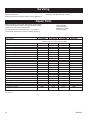
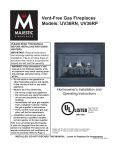
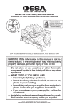
Installation and Operating Instructions for
Gas Log Heaters
Models: UVHK23MP, UVHK29MN,
UVHK31MP, UVHK36MN
Models with “N” after the model number use natural gas; models with “P” after the model number use propane (LP) gas.
This appliance operates as an unvented room heater certified under ANSI Z21.11.2b-2004 when fitted
to a solid fuel burning masonry or factory built fireplace with the flue damper closed. It also operates
as a decorative appliance under ANSI Z21.60b-2001.
CSA 2.26b-2001, when fitted to a solid fuel burning
masonry or factory built fireplace with the flue
damper open. When used as a decorative appliance, the use of a thermostat is not allowed. State
or local codes may only allow operation of this appliance in a vented configuration. Check your state
or local codes.
Split Bark Logs
Charred Oak Logs
WARNING
If the information in this manual is not followed exactly, a fire or explosion may result causing
property damage, personal injury or loss of life.
FOR YOUR SAFETY
— Do not store or use gasoline or other flammable vapors and liquids in the vicinity of this or
any other appliance.
•
•
•
WHAT TO DO IF YOU SMELL GAS
Do not try to light any appliance.
Do not touch any electric switch; do not use any phone in your building.
Immediately call your gas supplier from a neighbor’s phone. Follow the gas supplier’s instructions.
If you cannot reach your gas supplier, call the fire department.
•
—Installation and service must be performed by a qualified installer, service agency or the gas
supplier.
This is an unvented gas-fired heater. It uses air
(oxygen) from the room in which it is installed.
Provisions for adequate combustion and ventilation air must be provided. Refer to Section Provisions For Adequate Combustion and Ventilation
Air - Page 6.
This appliance may be installed in an aftermarket,
permanently located, manufactured (mobile) home,
where not prohibited by local codes.
This appliance is only for use with the type of gas
indicated on the rating plate. This appliance is not
convertible for use with other gases.
INSTALLER: Leave this manual with the appliance.
CONSUMER: Retain this manual for future reference.
20008056 1/07 Rev. 2
Table of Contents
Important Information .................................................................................................................. 3
Important Safeguards ............................................................................................................... 4
Installation Requirements ......................................................................................................... 5
High Elevations ......................................................................................................................... 5
Pressure Test Points ................................................................................................................. 5
Odor During Operation .............................................................................................................. 5
Provisions For Adequate Combustion Air ................................................................................. 7
Installation
Unpacking ................................................................................................................................. 9
Fireplace Preparation ................................................................................................................ 9
Location .................................................................................................................................... 9
Clearances ................................................................................................................................ 9
Gas Connection ...................................................................................................................... 11
Typical Gas Line Connection .................................................................................................. 11
Gas Line Pipe Sizing ............................................................................................................... 12
Gas Pressure Check ............................................................................................................... 12
Lighting Instructions ................................................................................................................ 13
Turning Off Gas to Appliance .................................................................................................. 13
Match Lighting ......................................................................................................................... 13
Flame Check ........................................................................................................................... 14
Managing Heat Output ............................................................................................................ 14
Maintenance
Cleaning .................................................................................................................................. 14
Positioning Logs ...................................................................................................................... 15
Fireplace Screen ..................................................................................................................... 15
Decorative Volcanic Ash ......................................................................................................... 15
Servicing ..................................................................................................................................... 18
Repair Parts ................................................................................................................................ 18
Warranty ..................................................................................................................................... 19
2
20008056
Important Information
WARNING: Any change to this heater or its controls can be dangerous.
In the Commonwealth of Massachusetts, all gas fitting and
installation of this heater shall only be done by a licensed
gas fitter or licensed plumber.
• Due to high temperatures, the appliance should be located out of traffic and away from furniture and draperies.
• The appliance area must be kept clear and free from combustible materials, gasoline and other flammable vapors and
liquids.
• Children and adults should be alerted to the hazard of
high surface temperatures and should stay away to avoid
burns or clothing ignition.
• Installation and repair must be done by a qualified service person or gas appliance installer.
• The appliance must be inspected before use and at least
annually by a professional service person. More frequent
cleaning may be required due to excessive lint from carpeting, bedding material, dust and pet hair, etc. It is important
that the control compartment, burners and circulating air
passageways of the appliance be kept clean.
• DO NOT place clothing or other flammable material on or
near the appliance.
• This appliance must only be used with pressures at the inlet
as shown in Table 1, Page 12.
• The installation must conform with local codes or, in the
absence of local codes, with the NATIONAL FUEL GAS CODE,
ANSI Z223.1/NFPA 54, latest edition.
• Any safety screen or guard removed for servicing an appliance must be replaced prior to operating the heater.
• The appliance and its appliance main gas valve must be
disconnected from the gas supply piping system during any
pressure testing of that system at test pressures in excess of
1/2 PSIG (3.5 kpa).
• The appliance must be isolated from the gas supply piping
system by closing its equipment shut-off valve during any testing of the gas supply piping system at test pressures equal to or
less than 1/2 PSIG.
• DO NOT use this heater in recreational vehicles, bedrooms
or bathrooms.
• If this is the ONLY gas appliance, we recommend a
minimum 200 pound cylinder with a fill gauge. Use of a 100
pound cylinder is not recommended. Other household gas
appliances may require the tank size to be larger. Do not
operate the vent-free heater if the fuel level in the propane
tank is below 1/4 full. Use only with two-stage regulator.
• DO NOT use this heater if any part of it has been under
water. Immediately call a qualified technician to inspect the appliance and replace any part of the control system and any gas
control which has been under water.
• Any outside air ducts in the fireplace shall be permanently
closed at the time of appliance installation.
• Check local, state or city codes to determine if unvented
heaters are permitted. If unvented heaters are not permitted, the fireplace chimney damper must be fixed at a
minimum dimension of 34 sq. inches. This must be accomplished by a clamp or screw on the chimney damper
20008056
to stop at the minimum vent area. The fireplace must also
have a minimum vent opening of 34 sq. ins., (Fig. 1)
• This appliance may be installed in an after-market* manufactured “mobile” home where not prohibited by state or local
codes.
• OUTSIDE AIR DAMPER OR ASH DUMP (IF PRESENT)
MUST BE CLOSED AND SEALED.
• Young children should be carefully supervised when
they are in the same room with the appliance.
• An unvented room heater having an input rating of more
than 10,000 btu per hour shall not be installed in a bedroom or bathroom.
• Keep the burner and control compartment clean. See maintenance instructions in this manual.
• Never use the heater at a setting between the positions
shown on the control knob as this can result in improper
combustion and excessive carbon monoxide emissions.
• The appliance must be operated with glass doors fully
open.
• DO NOT operate ceiling fan in room or area with logs when
logs are on.
• Solid fuels (i.e. wood, paper, trash) shall not be burned in a
masonry or UL 127 factory-built fireplace in which an unvented
room heater is installed.
*After-market: Completion of sale, not for purpose of re-sale
from the manufacturer.
WARNING: This appliance is for installation only
in a solid-fuel burning masonry or UL 127 factory-built fireplace or in a listed ventless firebox
enclosure. It has been designed certified for these
installations. Exception: DO NOT install this appliance in a factory-built fireplace that includes instructions stating it has not been tested or should
not be used with unvented gas logs.
WARNING: Do not allow fans to blow directly into
the fireplace. Avoid any drafts that alter burner
flame patterns.
WARNING: Do not use a blower insert, heat exchanger insert or other accessory not approved for
use with this heater.
Proposition 65 Warning: Fuels used in gas, woodburning or oil fired appliances, and the products of
combustion of such fuels, contain chemicals known to
the State of California to cause cancer, birth defects
and other reproductive harm.
California Health & Safety Code Sec. 25249.6
3
WARNING: If the area in which the heater may
be operated is smaller than that defined as an
unconfined space or if the building is of unusually tight construction, provide adequate combustion and ventilation air by one of the methods
described in the National Fuel Gas code, ANSI
Z223.1/NFPA 54, Section 5.3, (or applicable local
codes).
WARNING: During manufacturing, fabricating and
shipping, various components of this appliance are
treated with certain oils, films or bonding agents.
These chemicals are not harmful but may produce
annoying smoke and smells as they are burned off
during the initial operation of the appliance, possibly
causing headaches and eye/lung irritation. This is a
normal and temporary occurrence.
The National Fuel Gas Code, ANSI Z223.1/NFPA 54
defines a confined space as a space whose volume
is less than 50 cubic feet per 1,000 Btu per hour
(4.8m3 per kw) of the aggregate input rating of all
appliances installed in that space and an unconfined
space as a space whose volume is not less than 50
cubic feet per 1,000 Btu per hour (4.8 m3 per kw) of
the aggregate input rating of all appliances installed
in that space. Rooms communicating directly with
the space in which the appliances are installed,
through openings not furnished with doors, are considered a part of the unconfined space.
Important Safeguards
Although your gas logs are very realistic in appearance,
it is not a real wood-burning fireplace and must not be
used for burning rejected material.
To avoid irreparable damage to the appliance or personal injury; matches, paper, garbage or any other material must not
be placed or thrown on top of the logs or into the flames.
To avoid personal injury, do not touch hot surfaces when
the appliance is operating.
Touch only the piezo button and control knob. Avoid contact
with the front screen, canopy or any other part which will be
very hot.
Always ensure that the fireplace screen is in place when
the appliance is operating and, unless other provisions
for combustion air are provided, the screen shall have
opening(s) for introduction of combustion air.
Close supervision is necessary when the appliance is being operated near children.
Do not use to cook food.
If this is the ONLY gas appliance, we recommend a minimum
200 pound cylinder with a fill gauge. Use of a 100 pound
cylinder is not recommended. Other household gas appliances may require the tank size to be larger. Do not operate
the vent free fireplace if the fuel level in the propane tank is
below 1/4 full.
4
WARNING: The glowing ember base and all the
logs are manufactured from bonded ceramic
fiber. This is a commonly used material in industry worldwide. In the event of the logs and base
being removed, care should be taken not to damage the bonded material.
Intentional misuse of, or deliberately fragmenting, the material could lead to inhaling fibers and
be injurious to health.
This appliance is intended to be used only for supplemental
heat. Do not use it routinely as a primary heat source.
Continuous operation could produce excessive humidity depending on construction characteristics and outdoor temperatures (below 20°F). Over time, this could cause condensation
to form and damage wall structures and exterior paint.
WARNING: Failure to keep primary air
opening(s) of the burner(s) clean may result in
sooting and property damage.
20008056
Installation Requirements
The fireplace must meet the minimum dimensions listed below. (Fig. 1) Do not install the logset if the fireplace does
not meet these minimums.
Logset
Gas
UVHK36MN Natural
UVHK31MP Propane
UVHK29MN Natural
UVHK23MP Propane
Min. Fireplace Dimensions
A
B
C
D
Front Rear Overall Overall
Width Width Depth Height
28”
18”
14¹⁄₂”
17”
28”
18”
14¹⁄₂”
17”
17”
23”
16”
14¹⁄₂”
23”
16”
14¹⁄₂”
17”
Inlet Supply
Pressure (w.c.)
Min.
Max.
5.5”
14.0”
11.0”
14.0”
5.5”
14.0”
11.0”
14.0”
Manifold
Pressure
3.5”
11.0”
3.5”
11.0”
Low
Input
10,000
10,000
16,000
14,000
BTU/hr.
Med.
Input
22,500
20,000
---
High Air Shutter
Input
Setting
36,000 .136” (1)
31,000 .136” (2)
29,000 .136” (1)
23,000 .136” (2)
Pressure Test Points
The gas control is equipped with a captured screw-type
pressure test point, therefore it is not necessary to provide a 1/8” test point upstream of the control.
D
Odor During Operation
B
C
A
A. Front width
C. Depth
B. Rear width
D.FD370-2
Height
FD370-2
Fireplace
dimensions/vl18
3/25/99
High Elevations
Fig. 1 Minimum fireplace dimensions.
Input ratings are shown in BTU per hour and are
certified without deration from elevations up to
4,500 feet (1,370m) above sea level.
Nuisance outages may occur at altitudes above
4,500 feet (1,370m) if dirt, dust, lint and/or cobwebs are allowed to accumulate on burner and/or
ODS pilot. Monthly inspection and cleaning is
recommended for altitudes above 4,500 feet
(1,370m)
For elevations above 4,500 feet (1,370m) in USA,
installations must be in accordance with the
current ANSI Z223.1/NFPA 54 and/or local codes
having jurisdiction.
In Canada, please consult provincial and/or local
authorities having jurisdiction for installations at
elevations above 4,500 feet (1,370m)
20008056
Neither natural gas nor propane gas give off an odor
when burned. The nature of a vent free combustion
system, however, is such that odors may occasionally
be produced during heater operation when impurities
exist in the immediate area. Cleaning solutions, paint,
solvents, cigarette smoke, candles, adhesives, new carpet or textiles, etc., all can create fumes. These fumes
may mix with combustion air and can create odor. Such
odors will disappear over time, however, the condition
can be alleviated by opening a window or otherwise
providing additional ventilation to the area.
WARNING
This appliance is for installation in a solid-fuel
burning masonry, fireplace with a working flue,
a U.L.-127 listed manufactured solid-fuel burning fireplace, in any Majestic ventless firebox,
or in any listed ventless firebox enclosure
certified to I.A.S. U.S. Requirement 2-97 or
ANSI Z21.91.
NOTICE
This is an unvented gas-fired heater. It uses air
(oxygen) from the room in which it is installed.
Provisions for adequate combustion and ventilation air must be provided. Refer to Pages 7 and 8.
5
Model
Wood Burning Fireplace Series
BR/BC36, BR/BC36i
SHR36
BR/BC42, BR/BC42i
SHR42A/48/52
Vent Free Fireplace Series
UVDC36, UVDR36
UV36
UVDC42, UVDR42
UVSRC36A
UVSRC42A
Log Usage Chart
CVLS18
SLS18
CVLS24
SLS24
CVLS30
SLS30
UVHK36MN
★
★
X
X
UVHK36MN
X
★
X
X
X
UVHK36MN
X
X
X
X
UVHK31MP
★
★
X
X
UVHK31MP
X
★
X
X
X
UVHK31MP
X
X
X
X
UVHK29MN
X
X
X
X
UVHK29MN
X
X
X
X
X
UVHK29MN
X
X
X
X
-
UVHK23MP
X
X
X
X
UVHK23MP
X
X
X
X
X
UVHK23MP
X
X
X
X
-
★ with SLS24 and CVLS24 ONLY
WARNING: Refer to the above table to ensure that your log set is certified to be used in the CFM Corporation
Vent-Free firebox you have purchased. BR/BC and SHR models are designed as wood/solid fuel fireplaces. These
wood-burning models must be installed as a wood-burning unit including chimney and termination cap before the
installation of the vent-free logs.
6
20008056
Provisions for Adequate Combustion and Ventilation Air
WARNING: This heater shall not be installed in
a confined space or unusually tight construction unless provisions are provided for adequate
combustion and ventilation air.
Today’s homes are built more energy efficient than ever. New
materials, increased insulation and new construction methods
help reduce heat loss in homes. Home owners weather strip
and caulk around windows and doors to keep the cold air out
and the warm air in. During heating months, home owners
want their homes as airtight as possible.
While it is good to make your home energy efficient, you need
fresh air. All fuel-burning appliances need fresh air for proper
combustion.
Supplying Adequate Ventilation
This appliance must be installed in an unconfined space.
The following information will help you classify your space and
provide adequate ventilation for complete combustion.
An Unconfined Space has a minimum volume of 50 cubic
feet for each 1000 BTU/Hr input rating of all appliances in the
space. (4.8 M3 per kw), (cubic feet equals length x width x
height of space).
A Confined Space has a volume of less than 50 cubic feet for
each 1000 BTU/Hr input rating of all appliances in the space,
(4.8M3 per kw), (cubic feet equals length x width x height of
space).
Determining if You Have a Confined or Unconfined Space
Use this worksheet to determine if you have a confined or
unconfined space.
Space: Includes the room in which you will install heater plus
any adjoining rooms with doorless passageways or ventilation
grills between the rooms.
1. Determine the volume of the space (length x width x height).
Length x Width x Height = _____cu. ft. (volume of space)
Example: Space size 25’ (length) x 25’ (width) x 8’ (ceiling
height) = 5,000 cu. ft. (volume of space)
If additional ventilation from adjoining room(s) is supplied
with grills or doorless openings, add the volume of these
rooms to compute the total volume of the applicable space.
2. Divide the space volume by 50 cubic feet to determine the
maximum BTU/Hr the space can support.
________(volume of space) ÷ 50 cu. ft. = (Maximum BTU/
Hr the space can support.
Example: 5,000 cu. ft. (volume of space) ÷ 50 cu. ft. = 100
or 100,000 (maximum BTU/Hr the space can support)
3. Add the BTU/Hr of all gas burning appliances in the space.
Gas range
BTU/Hr
Vented gas heater
BTU/Hr
Gas fireplace logs
BTU/Hr
Other gas appliances* + BTU/Hr
Total
= BTU/Hr
Example:
Gas range
60,000 BTU/Hr
Vent-free logs
+ 29,000 BTU/Hr
Total
= 89,000 BTU/Hr
*Do not include direct-vent gas appliances. Direct-vent draws
combustion air from the outdoors and vents to the outdoors.
20008056
4. Compare the maximum BTU/Hr the space can support with
the actual amount of BTU/Hr used.
__________ BTU/Hr (maximum the space can support)
__________ BTU/Hr (actual amount of BTU/Hr used)
Example: 100,000 BTU/Hr (max. the space can support)
89,000 BTU/Hr (actual amount of BTU/Hr used)
The space in the above example is an unconfined space
because the actual BTU/Hr used is less than the maximum
BTU/Hr the space can support. If the space had been confined,
your options would be as follows:
A. Rework worksheet, adding the space of an adjoining
room. If the extra space provides an unconfined space,
remove door to adjoining room or add ventilation grills
between rooms. See Ventilation Air From Inside Building.
B. Install a lower BTU/Hr heater, if lower BTU/Hr size
makes room unconfined.
Converting Confined Space to Unconfined
Space
Additional volume to convert a confined to an unconfined space
could come from an adjoining space. When using an adjoining
space, you can provide two permanent openings: one within
12” of the ceiling and one within 12” of the floor on the wall
connecting the two spaces (see options 1 and 3, Figure 2), or
remove the door into the adjoining room.
Ventilation Air From Outdoors for Unusually
Tight Construction
WARNING: If the area in which the heater may be operated is smaller than that defined as an unconfined space
or if the building is of unusually tight construction, provide
adequate combustion and ventilation air by one of the
methods described in the National Fuel Gas Code, ANSI
Z223.1/NFPA 54, Section 5.3 or applicable local codes.
Unusually tight construction is defined as construction
where:
a. walls and ceilings exposed to the outside atmosphere have
a continuous water vapor retarder with a rating of one perm
(6 X 10.11 kg per pa-sec-m2) or less with openings gasketed
or sealed and
b. weather stripping has been added on openable windows
and doors and
c. caulking or sealants are applied to areas such as joints
around window and door frames, between sole plates and
floors, between wall-ceiling joints, between wall panels, at
penetrations for plumbing, electrical and gas lines and at
other openings.
If your home meets all of the three criteria above, you must
provide additional fresh air.
You may provide two permanent openings: one within 12” of
the ceiling and one within 12” of the floor. Connect these items
directly to the outdoors or spaces open to the outdoors. These
spaces include attics and crawl spaces. Follow the National
Fuel Gas Code NFPA 54/ANSI Z223.1, Section 5.3, Air for
Combustion and Ventilation for required size of ventilation grills
or ducts.
IMPORTANT: Do not provide openings for inlet or outlet air into
attic if attic has a thermostat-controlled power vent. Heated air
entering the attic will activate the power vent.
7
L
Flue Damper Closed for Unvented
Operation and Maximum Heat
Output
W
D
Flue Damper Locked Open
to a Minimum Venting Area
of 34 sq. in. (for areas where
unvented products are not
permitted)
NOTE: For round flue opening
minimum flue diameter (D) - 7”.
For square or rectangular flue
opening, length x width (L x W)
must equal 30 sq. in.
T104
Fig. 1 Minimum flue diameter and flue damper positions.
WARNING: Air openings that provide fresh air from an adjoining unconfined space shall not be blocked
T104
or obstructed in any way. Installation of
unit should allow a minimum of 2” clearance from any part of the
flue damper
heater to any of the ventilation openings.
10/27/03 djt
12”
Option 1
- Vents to
Adjoining
Room
Option 3 Vents to
Adjoining
Room
Option 2 Remove Door
to Adjoining
Room
12”
VO370-2
Fig. 2 Ventilation options for confined space.
8
vent370-2
Ventilation options
3/26/99 djt
20008056
Installation
Unpacking
Open the carton and remove the logs and the chassis. Remove
each of the logs by gripping at either end of the log while avoiding any undue pressure. Please note that the logs have been
marked for positive identification.
The carton for all models contains the following: chassis, front
log (#1), rear log (#2), top log (#3), [log (#4), log (#5) are included with larger models], 2 screws and a bag of volcanic ash.
Fireplace Preparation
The fireplace needs to be prepared before installing the unit:
A. Turn off the gas supply if the gas line has been run to the
fireplace.
B. WARNING: Before installing logs in fireplace, the chimney flue and firebox must be cleaned of soot, creosote,
ashes and loose paint by a qualified chimney cleaner or
sooting will occur.
Note: If your fireplace has been cleaned using chemicals or
solvents, these products may have been absorbed into the
fireplace hearth and walls and will be burned off during the
initial break-in period.
C. Any outside air ducts and/or ash dumps in the fireplace shall
be permanently closed and sealed at the time of appliance
installation. This will prevent drafts from disturbing the
flames and interfering with complete combustion of the gas
fuel.
Location
When gas logs are to be installed in a fireplace, inspect the
area surrounding it for possible air drafts that may affect the
flames and possibly cause sooting. Such drafts may be caused
by a ceiling fan near the fireplace, a hot air furnace register or
an open door. When burning the logs, carefully observe the
effect of possible drafts on the flames and take appropriate
measures to eliminate them. For example, the ceiling fan may
be cut off, the hot air register closed, etc.
Centrally locate the gas logs in the fireplace deep enough into
the firepit to accomplish an adequate draft (if use as a vented
appliance is planned). Ensure that the front feet of the grate sit
inside the front edge of the fireplace. Be sure fireplace meets
minimum fireplace dimensions.
To avoid any movement of the unit during operation, screw
the chassis to the floor of the fireplace using the screws
provided. Failure to do so could cause gas leaks.
Two brackets are provided. Place brackets over front grate legs
as shown in figure 3. After locating the chassis correctly in the
fireplace, mark the hole positions on the fireplace floor. Drill two
holes approximately 1/2” deep.
Use the two screws to secure the brackets to the fireplace floor,
(Fig. 3)
even when the appliance will be used as a vented decorative
appliance in case local codes change to allow unvented space
heaters or in the event that the flue damper is inadvertently
closed.
Clearances for unvented installation in existing fireplaces,
(jurisdiction permitting)
1. Sidewall Clearances: Clearances from the side of the
fireplace opening to any combustible wall should not be less
than 16”. (Fig. 4A)
2. Ceiling Clearances: The ceiling height should not be less
than 42” from the top of the fireplace opening. (Fig. 4A)
3. Mantel Clearances: The use of a canopy* is optional depending on mantel clearances to the fireplace opening and
projection profile.
NOTE: Mantel clearances may differ for each vent-free firebox. Refer to the firebox installation instructions for clearances.
A. Mantel profile: The minimum distance above the fireplace opening to combustible material projecting 11/8”
(tile moldings, breast boards, etc.) is 15”.
Combustible material projecting 6” (a mantel shelf, for
example) requires a minimum clearance of 19” above the
fireplace opening. Required clearance varies with the
amount of projection. (Fig. 4B)
The mantel profile must fall within the cross-section
shown in figure 4B (if no canopy is used) or 4C (if a
canopy is used).
B. With canopy*: The minimum distance above the fireplace opening to combustible material projecting 1¹⁄₈" (tile
moldings, breast boards, etc.) is 8".
Combustible material projecting 6" (a mantel shelf, for
example) requires a minimum clearance of 12" above the
fireplace opening. Required clearance varies with the
amount of projection. (Fig. 4C)
C. Heat resistant material: Any heat resistant material suitable for a continuous operating temperature of
120°C (248°F) must cover the wall surface directly above
the fireplace opening and extend the full width of the
fireplace opening for a distance of 10” above the opening
if no canopy is used, (8” if a canopy is used). (Figs. 4B
and 4C)
Clearances
NOTE: The following instructions regarding installation clearances and the use and installation of a canopy apply to use
of the appliances as an unvented space heater in permitting
jurisdictions. When installed as a vented decorative gas appliance, the clearances noted below and the use of a heat-deflecting canopy are not required.
However, it is recommended that these instructions be followed
20008056
Fig. 3 Use two (2) screws to secure the brackets to the fireplace floor.
9
No Canopy Used
10"
8"
27"
Min.
6"
42"
Heat Resistant
Material
1¹⁄₈"
16"
10"
Min.
15"
Min.
23"
Min.
19"
Min.
Fireplace Opening
Fig. 4A Minimum clearance to wall and ceiling.
Fig. 4B Mantel clearances for existing fireplaces.
10"
Universal
Canopy
8"
Min.
20"
Min.
12"
Min.
16"
Min.
Fireplace Opening
Fig. 4C Mantel clearance with Optional Universal Canopy,
UC-2 (black) or UC-2PB (polished brass).
T107
Mantel clearance
with canopy
10/27/03 djt
10
Mantel Leg
T105
Minimum
6"
clearance to
walls & ceiling
10/27/031¹⁄₈"
djt
Heat Resistant
Material
T106
Mantel
clearance
Noncombustible
Facing
no canopy
10/27/03 djt
Fireplace
Opening
2” Minimum
Clearance
Mantel Leg
Combustible Mantel
8"
Maximum Projection:
7”
Fig. 4D Side clearances and projection.
T107
side clearance
and projection
10/27/03 djt
20008056
Gas Connection
Typical Gas Line Connection
Check Gas Type. Use only the gas type indicated on the
heater’s rating plate. If the gas type indicated on the plate is
not your type of gas supply, DO NOT INSTALL. Contact your
dealer for the proper model.
Step 1: With the engine assembly free from the fireplace, check
tightness of flexible connector fittings.
CAUTION: Use one wrench to hold the valve and one
wrench to loosen and tighten the brass adapter and the flex
line connection. Failure to hold the valve while loosening
and tightening the fittings can damage the unit and cause
gas leaks.
Step 2: Set the engine assembly into the fireplace and connect
the flexible connector to the gas piping that has been installed
per local codes, or in the absence of local codes, ANSI Z223.1/
NFPA 54 latest edition.
Step 3: After the last connection is made, screw the engine assembly to the bottom of the fireplace. (Fig. 3)
Step 4: Test all connections on the unit and piping for gas
leaks.
Testing the Gas Piping. Test all piping for leaks. When checking gas piping to the heater with gas pressure less than 1/2
PSI, shut off manual gas valve for the heater. If gas piping is to
be checked with the pressure at or above 1/2 PSI, the heater
and manual shut off valve must be disconnected during testing
to prevent damage to the regulator on the unit, (see warning
below).
WARNING
DANGER OF PROPERTY DAMAGE,
BODILY INJURY OR DEATH.
Make sure the heater is equipped to operate on
the type of gas available. Models designated as
natural gas are to be used with natural gas only.
Heaters designated for use with liquefied petroleum (l.p.) gas have orifices sized for commercially pure propane gas. They cannot be used with
butane or a mixture of butane and propane.
Gas Piping. The gas supply line must be of an adequate size
to handle the BTU/HR requirements and length of the run for
the unit being installed.
Determine the minimum pipe size from the piping size chart on
Page 12. The normal gas connection at this appliance is 1/2”
NPT made at the left of the unit.
Always use an external regulator for all LP installations to reduce
the supply tank pressure to a maximum of 13” w.c. This is in addition to the regulator fitted to the heater.
All piping must comply with local codes and ordinances or with
the National Fuel Gas Code (ANSI Z223.1/NFPA 54), whichever
applies.
WARNING: Connecting directly to an unregulated
LP tank can cause an explosion.
Gas Connection. If installation is for L.P. gas, have L.P. installer use two-stage regulation and make all connections from
storage tank to heater. Refer to the National Fuel Gas Code for
the proper supply tank size with the Btu’s/Hr requirements. If
this is the ONLY gas appliance, we recommend a minimum 200
pound cylinder with a fill gauge. Use of a 100 pound cylinder
is not recommended. Other household gas appliances may
require the tank size to be larger.
Use two pipe wrenches when making the connection to the
valve to prevent turning or damage to gas valve or regulator.
Connection between the manual shut-off valve and the gas
valve can be made with a CSA design certified flexible connector if allowed by local codes. A 10 inch, 1/2” NPT listed stainless steel flexible connector is supplied with the gas log heater.
Tighten all joints securely.
CAUTION: Failure to install a drip leg (sediment trap)
may result in improper combustion that will produce soot.
Reference Sections 3.7 and 5.5.7 and Figure 5.5.7 of the
National Fuel Gas Code for guidance.
20008056
WARNING
DANGER OF PROPERTY DAMAGE,
BODILY INJURY OR DEATH.
Never use a match or open flame to test for leaks. Never
exceed specified pressures for testing. High pressures
may damage the appliance regulator which would require replacement. Liquefied petroleum (L.P.) is heavier
than air and it will settle in any low area, including open
depressions and it will remain there unless area is ventilatedNever attempt start-up of unit before thoroughly
ventilating area.A.
WARNING: Be sure that the gas type indicated on the
gas log rating plate concurs with the gas system in your
building.
To ensure that the gas lines and connections do not have any
leaks, a pressure test should be performed. Only a qualified
installer should perform the pressure test to ensure that
the unit is not damaged by high pressures!
If you connect natural gas to an LP gas unit, you may be unable to ignite the pilot. If the pilot does ignite, the front burner
flame on the low setting will be bright blue but only 1/4” to 1/2”
long and most likely lifting off the burner ports. If this is the
case, turn the unit off immediately and contact the dealer where
the unit was purchased.
If you connect LP gas to a natural gas unit, the front burner
flame on the low setting will be about 6” - 8” long. On the
medium and high setting, the front burner flames will be bright
yellow and about 10” in length. Turn the unit off immediately! If
the unit is allowed to run in this condition, substantial amounts
of soot will be generated and emitted into the house. Contact
the dealer where the unit was purchased.
11
Gas Line Pipe Sizing
NOTE: To determine the size of the branch gas line from the main gas line to the fireplace, enter the tables below (for
iron pipe or copper tubing) using the distance from the gas meter or second stage regulator to the furthest appliance on
the gas system. Select a pipe or tube diameter which has enough capacity to meet the maximum input requirement of
the fireplace. Regardless, do not use less than 1/2” diameter for the branch line. For any distances required longer than
shown in these tables, refer to the National Fuel Gas Code.
NOTE: There may be a local gas utility requirement specifying a minimum diameter for gas piping. All units require a 1/2 inch pipe connection at the gas valve.
CAPACITY OF PIPING
Cubic Feet per Hour based on 0.3” w.c. Pressure Drop
Specific Gravity for Natural Gas - 0.6 (1000 BTU/Cubic Foot)
Specific Gravity for Propane Gas - 1.6 (2550 BTU/Cubic Foot)
Length
of
Pipe
20’
30’
40’
50’
60’
70’
90’
100’
1/2” D
Natural Propane
92
73
63
56
50
46
40
38
Tubing Length
Feet
143
115
97
87
79
71
61
59
Nominal Inches for Iron Pipe Sizes (1,000s BTU/hr)
3/4” D
1” D
1¹⁄₄” D
Natural Propane Natural Propane Natural
Propane
190
152
130
115
105
96
84
79
296
237
202
179
163
151
130
122
350
285
245
215
196
180
160
150
546
444
380
334
304
280
250
235
730
590
500
440
400
370
320
305
1135
918
778
683
622
576
497
474
Outside Diameter Copper Tubing, Type L (1,000s BTU/hr)
1/2”
5/8”
3/4”
0.43
0.545
0.666
1¹⁄₂” D
Natural Propane
1100
890
760
670
610
560
490
460
1711
1385
1183
1043
949
872
763
717
7/8”
0.785
10
110
206
348
536
20
76
141
239
368
30
61
114
192
296
40
52
97
164
256
50
46
86
146
224
60
42
78
132
203
80
36
67
113
174
100
32
59
100
154
WARNING: Use only internally tinned copper tubing. If correct copper tubing is not used, tubing can deteriorate and develop
gas leaks.
Gas Pressure Check
Check the inlet pressure to the appliance to ensure that it is as
shown in Table 1. Also check the incoming gas pressure where
the field installed gas line connects to the gas logs.
The manifold pressure is controlled by the regulator and should
be checked at the pressure test point located downstream from
the regulator on the control valve body. Access to the pressure
test point is obtained by removing all logs and the heat shield
on the right hand rear side of the base. The pressure test point
1/8” NPT plugged tapping is located on the rear face of the
control body. (Fig. 5)
The pressure should be checked with the appliance burning on
high (highest setting) and all other gas appliances turned on.
One must then read the manometer and if pressures are not
10” w.c. for LP or 3.5” w.c. for natural gas, then the inlet pressure must be adjusted or increased until the proper pressures
are attained. If these pressures are greater than 10” w.c. for
LP or 3.5” w.c. for natural gas, contact your gas supplier before
operating the appliance.
The pressure regulator is preset and locked to prevent tampering. If the pressure is not as specified, replace the regulator
with part # 73332 (for natural gas only), or part # 73333 (for L.P.
gas only).
12
Table 1
Gas Inlet Pressure
Max.
Normal
Min.*
Regulator Pressure
Natural
10.5” w.c.
7” w.c.
5.5” w.c.
3.5” w.c.
Propane
13” w.c.
11” w.c.
11” w.c.
10.0” w.c.
*Minimum inlet supply pressure for the purpose of input adjustment.
After measuring the pressure, replace the test point plug and
check for leaks. Replace the control box cover and the two
phillips head screws.
CAUTION: If the appliance’s operating pressures are not
checked and adjusted, improper combustion may result in soot
being produced.
Test Point
T126
Fig. 5 Pressure test point.
T126
20008056
For Your Safety, Read Before Lighting
WARNING: If you do not follow these instructions exactly, a fire or explosion may result causing property damage,
personal injury or loss of life.
A. This appliance has a pilot which must be lighted by hand.
When lighting the pilot, follow these instructions exactly.
B. BEFORE OPERATION smell all around the appliance
area for gas. Be sure to smell
next to the floor because some
Fig. 6
gas is heavier than air and will
settle on the floor.
WHAT TO DO IF YOU SMELL
GAS:
•
•
•
•
• If you cannot reach your gas supplier, call the fire depart-
ment.
C. Use only your hand to push in
Clockwise
or turn the gas control knob.
Fig. 7
Never use tools. If the knob
3
will not push in or turn by hand,
4
2
don’t try to repair it. Call a
qualified service technician.
Force or attempted repair may 1/IGN
cause a fire or an explosion.
Piezo
Do not try to light any appliance.
D. Do not use this appliance if
Off
any part of it has been under
Do not touch any electrical switch;
water. Immediately call a
do not use any telephone in your building.
qualified service technician to
Immediately call your gas supplier from a neighbor’s teleinspect the appliance and to
phone.
T118
replace any part of the control system or gas control which
Follow the gas supplier’s instructions.
Lighting Instr
has been under water.
Piezo
Lighting
10/28/03 Instructions
djt
1. STOP! Read the safety information above before proceeding.
2. Refer to Figure 7. To turn off the gas supply, depress the
knob slightly and turn clockwise
to the OFF position.
3. Wait five (5) minutes to clear out any gas. Then smell for
gas, including near the floor. If you smell gas, STOP! Follow “B” in the safety information above. If you don’t smell
gas, go to the next step.
4. Refer to Figure 8.
Locate the pilot. It is at
the right of the front main
burner next to the control
knob.
5. Refer to Figure 9.
Fig. 8
Push in the control knob
and turn counterclockwise
to the 1/IGN position.
Hold the control knob in for a few seconds.
6. While still holding in the control knob, press the ignitor pushbutton several times. This will cause a spark at the pilot
T129
which will ignite the pilot gas.
manual lighting
7. Hold the control knob for 20 seconds to10/29/03
prevent
djtthe flame
failure detector from shutting off the gas while its probe is
warming up.
8. Release the control knob.
T127
Manual knob
10/29/03 djt
• If the knob does not pop up when released, stop and immediately call your service
technician.
Counterclockwise
• If the pilot will not stay lit after
Fig. 9
several tries, turn the gas
3
control knob to OFF and call
4
2
your service technician or gas
supplier.
9. When the pilot remains lit, turn
1/IGN
the control knob counterclockwise
to the setting you
Off
prefer.
10. Refer to the table on Page 5
for setting positions.
11. This appliance is fitted with a transient pilot burner for the
sole purpose of safe, momentary ignition of the main burner
in conjunction with the piezo ignitor. When in operation with
the main burner, it contributes to the baseT127
heat release and
is turned off by turning the control knob toManual
the OFF
knobposition.
djt
12. The control knob should not be left at the 10/29/03
ignition setting
after the pilot has been ignited.
To Turn OFF Gas to Appliance
Depress the control knob slightly and turn it clockwise
to the OFF position. Refer to Figure 7.
Match Lighting
If the pilot cannot be ignited with the piezo, it can be manually
lit with the use of a match and lighter rod.
1. Place the match in the holder and light. With the right
hand, depress and turn the control knob counterclockwise
(Fig. 9) to the “IGN” position. Hold in for 20
seconds.
20008056
2. Take the lighter rod and lighted match and ignite the pilot
.(Fig. 8)
3. Continue to hold the control knob for an additional 20 seconds to ensure pilot is maintained.
4. Proceed with Step 8 in Lighting Instructions.
13
Flame Check
A periodic visual check of the flames should be made. The pilot
flame should always be present when the appliance is in operation. (Fig. 10)
In normal operation (at full rate for approximately 15 minutes)
the following flame appearance should be observed:
Natural Gas
Main BurnerFlame: The flame should be yellow in color and
should extend about 6 inches above the large front log.
Typical flame shape as seen in Figure 11.
NOTE: For your safety, the appliance is equipped with an
oxygen depletion system. The system senses the oxygen in the
atmosphere and switches off the gas supply in case the level of
oxygen falls below a safe level. It must not be altered in any
way.
Propane Gas
T279
T123
Fig. 10 Correct pilot flame appearance.
Fig. 11 Correct log flame appearance.
����
T123a
Managing Heat Output
��������������
manual burner flame
10/29/03 djt
����
wood burning fireplace, the heat output
operated as a decorative appliance whose prime function lies in
When installed in a
from the appliance can be controlled by the position of the flue
damper if it is installed in a wood-burning fireplace.
The damper setting should be fully closed for maximum heat
output, partially closed for less heat output and fully open for
minimum heat output.
The appliance may be used in a working solid fuel burning fireplace with the flue damper closed only if unvented appliances
are permitted by local state and city codes. It may also be
the aesthetic effect of the flames when installed in a solid fuel
burning fireplace with the flue damper open. If unvented heaters are not permitted, the fireplace vent damper must be locked
at a minimum vent area of 15 sq. ins.
Whenever the appliance is operated with the fireplace’s flue
damper closed, glass doors - if present - must be open and
the outside air damper and the ash dump (if the fireplace is
equipped with either one) must be closed.
Maintenance
Cleaning
CAUTION: Before cleaning or moving logs or other parts of the
unit, be sure to read the section on important safeguards.
Cleaning should be done before the logs are used each year
and after long periods of non-use.
All cleaning should be carried out when the appliance is cold.
Only limited cleaning will be required under normal use. Dusting the front grate or the control knob panel may be required
occasionally. Do not use any cleaning fluids to clean the logs or
any other part of the appliance.
If the flames show any unusual shapes or behavior, or if the
burners fail to ignite properly, then the burner holes may require
cleaning. If this occurs contact your nearest dealer to get the
appliance serviced.
14
Alternatively, the appliance can be cleaned by removing the top,
front and rear logs. Handle the logs gently so as not to damage
them. Always lift each log by holding it carefully at each end.
After the logs are removed allowing access to the burner area,
use a vacuum cleaner to carefully remove dust, spider webs
and loose particles from the base, logs and from around the
burner. Gloves are recommended to prevent the ceramic fibers
that compose the logs from pricking your skin. If the skin is
pricked, wash gently with soap and water. Use extreme caution in clearing around the pilot (ODS). The pilot should not be
moved or altered from the original factory setting (Pilot to burner
preset location). The burner should not be removed or taken
out of it’s locked and secure position (proper location of burners
are critical).
20008056
Positioning Logs
The logs must be positioned ONLY as illustrated in Figures 12,
13 and 14
• Position the front log so that the large notch in the underside
•
•
of the right end of the log fits securely and rests on the sheet
metal control cover as shown in Figure 15. The front right
end of the log has a ‘V’ shaped notch to touch the back of the
right-hand grate bar as shown in Figure 16. The left underside of the front log has a tab that will fit into mating slot in the
ember base. When the log is properly placed, there should
be no gap between the right underside of the front log and
the top edge of the ember base.
CAUTION: Failure to position these parts as they are
described in these instructions will cause improper combustion and may result in soot being produced.
Position the rear log so that the notches in the back of the
log go around and up against the vertical bars of the grate
assembly. Install the rear log behind the log spacer brackets.
The bracket in the center of the burner assembly must fit into
the hole in the center underside of the back log. (Refer to
Figure 17 for proper placement of the rear log.)
Position the top log so that its tongue fits securely into the slot
on the top of the rear log and the peg fits into the hole in the
top of the front log. The top log, when properly positioned,
establishes the correct spacing between the front and rear
logs.
• The left and right twigs are to be placed into the appropriate
notches provided in the front and rear logs as shown. (Figs.
12, 13 and 14)
• When using the Charred Oak log set the rear standoff must
be cut to allow the rear log to be positioned properly. (Fig.
17)
ENSURE THAT THE LOGS ARE CENTRAL AND VERTICAL
AS SEEN FROM THE SIDE. TO PREVENT UNWANTED
SOOTING, THE FLAME FROM THE BACK BURNER SHOULD
NOT TOUCH ANY LOG.
CAUTION: Proper location is critical. When positioning the log
set, make sure that the logs do not interfere with the sides of
the fireplace before securing the chassis.
Fireplace Screen
The fireplace screen must be in place when the appliance is
operating and unless other provisions for combustion air are
made, the screen must have openings for the introduction of
combustion air.
Decorative Volcanic Ash
The volcanic ash from the bag provided should be sprinkled
over the baseplate in front of and below the main burner. Do
not sprinkle this material on the fiber base, around the pilot or
on the main burner.
Split Bark Logset
Fig. 12 Split Bark logset position.
WARNING: Failure to position the parts in accordance with
this diagram or failure to use only parts specifically approved with this heater, may result in property damage or
personal injury. Do not alter the logs!
20008056
15
Charred Oak Logset
Fig. 13 Charred oak logset positions.
WARNING: Failure to position the parts in accordance with
this diagram or failure to use only parts specifically approved with this heater, may result in property damage or
personal injury. Do not alter the logs!
Charred Oak Logset
Fig. 14 Charred oak logset correct potitions.
16
20008056
Control
Cover
Valve
Cover
Log Spacer
Bracket
All Other
Logsets
Charred Oak
Only
Rear Log Bracket
T100
Fig. 15 Position log so notch fits securely and rests on valve
cover.
Front Log
T100
log notch
on valve cover
10/15/03 djt
T124
Fig. 17 When using Charred Oak logsets, the rear log spacer
bracket must be cut for the rear log to sit properly.
T124
Side view
logset
10/28/03 djt
End Bar Should
Fit in V-Shaped
Depression in the
Bark
T101
Fig. 16 Front end of frontlog should touch grate bar.
T101
secure front log
10/15/03 djt
20008056
17
Servicing
Repair and replacement work should only be done by a qualified service technician.
Always shut off the gas supply and make sure the appliance is
cool before beginning any service operation.
Always check for gas leaks after servicing.
Repair Parts
Always include the correct name, part number, model number,
control type and serial number of the appliance when ordering
service parts. Refer to the parts list below.
Use manufacturer’s authorized parts only. If you desire to
communicate with the factory, write to Customer Service at:
Description
Logs
Right Hand Grate Assy
Left Hand Grate Assy
Front Grate Assy
Base Plate
Ceramic Fiber Base
Rear Burner Injector
Main Burner Injector
Restrictor
Rear Burner
Main Burner
Control Valve
Regulator (Nat.)
Regulator (LP)
ODS (Natural) Pilot OP
ODS (LP) Pilot OP
Copreci (Natural) Pilot
Copreci (LP) Pilot
Control Knob
Shaft Extended Assy
Cotter Pin
Piezo Ignitor
Wire Ignitor
Hardware Bag Assy
Volcanic Rock Assy
Tube, Flexible Gas Inlet
CFM Corporation
410 Admiral Blvd.
Mississauga, Ontario
Canada L5T 2N6
UVHK29MN
UVHK23MP
UVHK36MN
UVHK31MP
Replacement logs may only be ordered in sets.
Refer to Page 3 for correct log set number.
72006
72006
72006
72006
72005
72005
72005
72005
69649
69649
69305
69305
71149
71149
71150
71150
71579
71579
71578
71578
76375
76377
71843
71223
69660
71185
69211
69341
71213
71212
76116
76116
72689
72689
69720
69720
69340
69340
70683
70683
69233
69233
73332
73332
73333
73333
20001356
20001356
74556
74556
78574
78574
78575
78575
70681
70681
69208
69208
71243
71243
71243
71243
69293
69293
69293
69293
65180
65180
65180
65180
76846
76846
76846
76846
70113
70113
70113
70113
68688
68688
68688
68688
71598
71598
71598
71598
CFM Corporation reserves the right to make changes in design, materials, specifications, prices and discontinue colors and products at any time,
without notice.
18
20008056
LIMITED 2/20 YEAR WARRANTY
For Majestic Fireplaces Vent-Free Gas Appliances
CFM Corporation (Company) extends the warranties specified in paragraphs A and B below with respect to its Majestic
Fireplaces Decorative Gas Appliances (the “Gas Appliance”),
including the CFM Corporation supplied accessories and components referred to in those paragraphs, subject to the following
conditions and limitations:
1. These warranties are extended only to the Gas Appliance
installed in the continental United States, including Alaska,
and Canada; only if and so long as the accordance with the
installation and operating instructions furnished therewith;
and only if and so long as Gas Appliance is not removed
from its original installation.
2. These warranties are limited to only the component parts
manufactured and supplied by CFM Corporation. The use
of components manufactured by others with the Gas Appliance could create serious safety hazard, may result in the
denial of certification by recognized national safety agencies, and could be in violation of local building codes.
3. The Gas Appliance must be operated at all times in accordance with the operating instruction furnished therewith.
The Gas Appliance is designed to burn either natural or
propane gas only. Burning conventional fireplace fuels such
as wood, coal, or any other solid fuel will cause damage to
the Gas Appliance, will produce excessive temperatures and
will result in a fire hazard.
4. These warranties are limited to repair, replacement or furnishing a replacement for sale, as specified in Paragraphs
A and B, for a part found to CFM Corporation satisfaction,
after examination, to be defective in materials or workmanship under normal conditions, use and service.
5. All obligations with respect to these warranties may be fully
discharged by CFM Corporation refunding the wholesale
price of a defective part.
6. Except as otherwise expressly specified in Paragraphs A
and B. NONE OF THESE WARRANTIES COVER, AND
CFM CORPORATION SHALL NOT BE RESPONSIBLE
FOR, ANY CONSTRUCTION, INSTALLATION, LABOR,
TRANSPORTATION OR OTHER COSTS OR EXPENSES
ARISING FROM A DEFECTIVE PART, ITS REPAIR OR
REPLACEMENT OR OTHERWISE, NOR SHALL CFM
CORPORATION IN ANY EVENT BE RESPONSIBLE FOR
ANY INDIRECT, INCIDENTAL OR CONSEQUENTIAL DAMAGES. EXCEPT TO THE EXTENT PROVIDED BY LAW,
THERE ARE NO IMPLIED WARRANTIES WITH RESPECT
TO THE GAS APPLIANCE, ITS COMPONENTS AND ACCESSORIES (INCLUDING IMPLIED WARRANTIES OF
MERCHANTABILITY OR FITNESS FOR A PARTICULAR
PURPOSE), ALL OF WHICH ARE HEREBY EXPRESSLY
20008056
INCLUDED. IN NO EVENT SHALL ANY IMPLIED WARRANTY PRESCRIBED BY LAW (NOTWITHSTANDING THE
FOREGOING EXPRESS EXCLUSION) REMAIN IN EFFECT AFTER EXPIRATIONS OF THE WARRANTIES SET
FORTH IN PARAGRAPHS A AND B.
A. Gas Appliances, electrical and manual compon
ents, glass panels, all sealants or adhesives and
optional accessories (exclusive of CFM Corporation
supplied decorative logs which are covered by a separate warranty under paragraph B below):
Within two years from the date of manufacture of the gas
appliance, CFM Corporation will repair, or replace (at our
option) a defective part without charge.
B. CFM Corporation cement logs, fiber logs, or firebox
liners:
Within two years from the date of manufacture of the gas
appliance, CFM Corporation will replace a defective part
without charge. Within years three through twenty from
the date of manufacture of the gas appliance, CFM Corporation will provide a replacement for a defective part
to the homeowner, but assumes no liability for incurred
labor cost.
The foregoing warranties gives you specific legal rights and
you may also have other rights which vary from state to state.
Some states do not allow limitations on how long an implied
warranty may last, so the limitation specified above on the duration of any implied warranty prescribed by law may not apply
to you. Similarly, some states do not permit the exclusion or
limitation of incidental or consequential damages, so the above
exclusion of such damages may not apply to you.
In order to obtain performance of any of the above warranty
obligations, write to CFM Corporation at this address:
CFM Corporation
410 Admiral Blvd.
Mississauga, Ontario Canada L5T 2N6
Attention: Director of Warranty Services
Since local building requirements may vary greatly throughout
the country, users of CFM Corporation products should determine in advance whether there are any building
code restrictions on the use of a specified product.
CFM CORPORATION MAKES NO REPRESENTATION OR
WARRANTY REGARDING, AND SHALL NOT BE RESPONSIBLE FOR, ANY BUILDING CODE COMPLIANCE.
The foregoing warranties give you specific legal rights and you
may also have other rights which vary from state to state.
19
CFM Corporation
410 Admiral Blvd. • Mississauga, Ontario, Canada L5T 2N6
800-668-5323 • www.cfmcorp.com