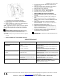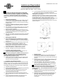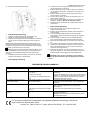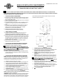
1
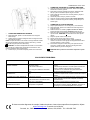
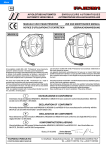
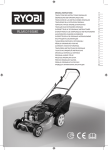
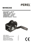
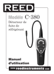
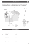
INSTALLATION AND MAINTENANCE MANUAL FORM #PM-002 REV B 12/09 SPRING RETRACTABLE HOSE REELS: SERIES SLP, SMP, DLP, DMP, V-SLP, VA-DLP SLP V-SLP DLP COXREELS The technical data and images which appear in this manual are for informational purposes only. NO WARRANTIES, EXPRESS OR IMPLIED, INCLUDING WARRANTIES OF MERCHANTABILITY OR FITNESS FOR A PARTICULAR PURPOSE, ARE CREATED BY THE DESCRIPTIONS AND DEPICTIONS OF THE PRODUCTS SHOWN IN THIS MANUAL. COXREELS makes no warranty (and assumes no liability) as to function of equipment or operation of systems built according to customer design or of the ability of any of its products to interface, operate or function with any portions of customer systems not provided by COXREELS. COXREELS agrees to repair or exchange the goods sold hereunder necessitated by reason of defective workmanship and material discovered and reported to COXREELS within two years after shipment of such goods to Buyer. Except where the nature of the defect is such that it is appropriate, in COXREELS’ judgment, to effect repairs on site, COXREELS’ obligation hereunder to remedy defects shall be limited to repairing or replacing (at COXREELS’ option) FOB point of original shipment, any part returned to COXREELS at the risk and cost of Buyer. Defective parts replaced shall become the property of COXREELS. COXREELS shall only be obligated to make such repair or replacement if the goods have been used by Buyer only in service recommended. COXREELS is not responsible for defects which arise from improper installation, neglect, improper use of or from normal wear and tear. COXREELS obligation shall be limited by the manufacturer’s warranty (and is not further warranted by COXREELS) for all parts procured from others according to published data, specifications or performance information not designed by COXREELS. COXREELS further agrees to replace or at COXREELS’ option to provide a refund of the sales price of any goods that do not conform to applicable specifications or which differ from that agreed to be supplied which non-conformity is discovered and forthwith reported to COXREELS within 30 days after shipment to the Buyer. COXREELS’ obligation to replace or refund the purchase price for nonconforming goods shall arise once Buyer returns such goods FOB point of original shipment by COXREELS at the risk and cost of Buyer. Goods replaced by COXREELS shall become property of COXREELS. COXREELS liability on any claim, whether in contract, tort (including negligence), or otherwise, for any loss or damage arising out of, connected with, or resulting from the manufacture, sale, delivery, resale, repair, replacement or use of any products or services shall in no case exceed the price paid for the product or services or any part thereof which give rise to the claim. In no event shall COXREELS be liable for consequential, special, incidental or other damages, nor shall COXREELS be liable in respect of personal injury or damage to property not the subject matter hereof unless attributable to gross misconduct of COXREELS, which shall mean an act or omission by COXREELS demonstrating reckless disregard of the foreseeable consequences thereof. COXREELS is not responsible for incorrect choice of models or where products are used in excess of their rated and recommended capacities and design functions or under abnormal conditions. COXREELS assumes no liability for loss of time, damage or injuries to property or persons resulting from the use of COXREELS products. Buyer shall hold COXREELS harmless from all liability, claims, suits and expenses in connection with loss or damage resulting from operation of products or utilization of services, respectively, of COXREELS and shall defend any suit or action which might arise there from in Buyer’s name – provided that COXREELS shall have the right to elect to defend any such suit or action for the account of Buyer. The foregoing shall be the exclusive remedies of the Buyer and all persons and entitles claiming through the Buyer. NOTE: All designs, specifications, and dimensional data contained in this publication are subject to change without notice. WARNING – APPLICATION THE PRODUCTS IN THIS INSTALLATION AND MAINTENANCE MANUAL HAVE BEEN TESTED UNDER CONTROLLED LABORAROTY CONDITIONS TO MEET SPECIFIC TEST CRITERIA. THESE TESTS ARE NOT INTENDED TO REFLECT THE PERFORMANCE OF THE PRODUCTS OR ANY OTHER MATERIAL IN ANY SPECIFIC APPLICATION, BUT ARE INTENDED TO PROVIDE THE USER WITHY APPLICATION GUIDELINES. THE PRODUCTS ARE INTENDED FOR USE BY KNOWLEDGEABLE PERSONS HAVING THE TECHNICAL SKILL NECESSARY TO EVALUATE THEIR SUITABILITY FOR SPECIFIC APPLICATIONS. WARNING – USER RESPONSIBILITY THE USER, THROUGH ITS OWN ANALYSIS AND TESTING, IS SOLELY RESPONSIBLE FOR MAKING THE FINAL SELECTION OF THE SYSTEM AND COMPONENTS AND ASSURING THAT ALL PERFORMANCE, ENDURANCE, MAINTENANCE, SAFETY AND WARNING REQUIREMENTS OF THE APPLICATION ARE MET. TO THE EXTENT THAT COXREELS PROVIDE COMPONENT OR SYSTEM OPTIONS BASED UPON DATA OR SPECIFICATIONS PROVIDED BY THE USER, THE USER IS RESPONSIBLE FOR DETERMINING THAT SUCH DATA AND SPECIFICATIONS ARE SUITABLE AND SUFFICIENT FOR ALL APPLICATIONS AND REASONABLY FORESEEABLE USES OF THE COMPONENTS OR SYSTEM. WARNING – SAFETY READ ALL SAFETY INSTRUCTIONS CAREFULLY BEFORE ATTEMPTING TO INSTALL, OPERATE, OR MAINTAIN THIS PRODUCT. ONLY QUALIFIED PERSONNEL SHOULD UNDERTAKE THE INSTALLATION AND COMMISSIONING OF THIS PRODUCT. FAILURE TO COMPLY WITH INSTRUCTIONS COULD RESULT IN PERSONAL INJURY AND/OR PROPERTY DAMAGE. FAILURE TO FOLLOW RECOMMENDED APPLICATION INFORMATION AND RECOMMENDED PROCEDURES FOR SELECTION, INSTALLATION, CARE, MAINTENANCE AND STORAGE OF REEL ASSEMBLY, SWIVEL, HOSE, COUPLINGS OR HOSE ASSEMBLIES MAY RESULT IN FAILURE TO PERFORM PROPERLY AND MAY RESULT IN DAMAGE TO PROPERTY AND SERIOUS BODILY INJURY. FOLLOW GOOD MAINTENANCE PRACTICES – ESTABLISH A PROGRAM OF INSPECTION, TESTING AND REPLACEMENT OF REEL COMPONENTS FROM FACTORS INCLUDING: o SEVERITY OF APPLICATION, FREQUENCY OF EQUIPMENT USE, AND PAST PERFORMANCE OF REEL COMPONENTS ONLY PROPERLY TRAINED PERSONS SHOULD INSPECT, TEST OR SERVICE REEL AND HOSE/CABLE ASSEMBLIES. PERIODIC UPDATING OF TRAINING IS RECOMMENDED. DOCUMENT MAINTENANCE, INSPECTIONS AND TESTING. PROP 65 WARNING: Handling of brass material on this product exposes you to lead, a chemical known to the State of California to cause birth defects or other reproductive harm. “WASH HANDS AFTER USE” Page 1 of 4 For assembly drawings, parts lists, or specific repair instructions, refer to web site at www.coxreels.com or consult factory. Coxreels, Inc., 5865 S. Ash Ave., Tempe, Arizona, USA, 85283 Tel: 1-800-269-7335 INSTALLATION AND MAINTENANCE MANUAL FORM #PM-002 REV B 12/09 SAFETY • PRESSURE WARNINGS • • • Multipurpose hose is installed with tube compounded for maximum oil resistance. Hose can be used for air, water, oil and many other chemical applications. Operational temperature ranges vary across the wide range of hose options. (Please refer to the COXREELS catalog, website or contact Customer Service for hose specific data). Hose reels should not be used at temperatures below or above the rating of the hose. The operational rating of a reel not equipped with hose is determined by the capacity of the installed hose. The pressure rating of the reel without hose must not be greater than the than the operational capacity of a reel. (Please refer to the COXREELS catalog, website or contact Customer Service for reel/hose specific data). Variations in the OD of higher rated hose will affect the operational capacity of the reel. • This equipment should be properly installed before use in accordance with local codes and ordinances. The pressure from the hose reel should be disconnected from the hose reel before any service functions are performed. This hose reel must not be used for pressure greater that the rating listed in the COXREELS catalog / website www.coxreels.com. • OPERATIONAL WARNINGS • • • • Exercise care when handling the hose reel during normal operation. Some hose reels have a rotating drum powered by a spring under tension. Do not use hose different from that for which the reel is intended. Changes in diameter, weight per foot, length of hose or flexibility (Minimum Bend Radius) will affect the operation of the reel. Mounting hardware and fasteners should be installed to maintain tightness under vibration and checked periodically to ensure tightness. Overhead installation mountings should be such that the reel is not solely supported by bolts in tension. A safety chain, cable, enclosure or netting is strongly recommended to minimize damage and/or possible injury in the event of a mounting failure. LABELS & MARKINGS Hose Reels with and without hose • The marking of the hose reel provided with or without hose includes the following o The label on the frame includes the COXREELS name and Logo, the product catalog number, the individual product serial number, PSI rating and what type and length of hose intended for use on the reel. o The maximum pressure rating for every hose reel supplied without house is marked on the COXREELS Identification Label. In absence of this information, refer to website, catalog, or customer service. Actual rating is determined by the installed hose and is not to exceed the indicated maximum operational rating. The pressure rating of the hose installed on reels provided without hose must be marked on the label upon installation. MAINTENANCE WARNINGS • • Modification of the equipment may cause excessive wear and will void the warranty. Contact COXREELS regarding changes or modifications of equipment which could affect reliability or safety. DO NOT DISASSEMBLE A SPRING MOTOR FOR ANY REASON! Serious personal injury could result. Some hose reels are equipped with a spring under tension. Contact COXREELS for assistance. PERSONAL SAFETY • • SPECIFICATIONS & LISTINGS • • • The identified Series of Hose Reel products within this manual are not certified or listed by any independent certifying or regulatory body. This series of hose reels is intended for industrial use and are provided with permanent mounting means. • • • Ensure reel has been properly installed before connecting supply line. Before connecting to reel, be certain supply line does not exceed rated pressure of the hose reel. If reel was purchased without hose, thoroughly review the “Hose Installation” instructions to properly install hose. Perform “Operational Check” per instructions to ensure reel is operating properly. NEVER use a spring retractable reel that is not performing as intended. If a leak should occur after applying pressure to the reel, immediately discontinue supply line pressure. PRESSURE & TEMPERATURE RATING • WARNING: Prevent static sparking. When working around flammables, ensure that the hose reel, hose, and equipment are properly grounded. All reels covered in this manual with or without hose have specific P.S.I. ratings. (Please refer to the COXREELS catalog, website or contact Customer Service for Reel specific data). Reels should not be used at pressures greater that the rating of the hose. INSTALLATION WARNING: READ THESE INSTRUCTIONS CAREFULLY BEFORE ATTEMPTING TO INSTALL, OPERATE, OR MAINTAIN THIS PRODUCT. ONLY QUALIFIED PERSONNEL SHOULD UNDERTAKE THE INSTALLATION AND COMMISSIONING OF THIS PRODUCT. FAILURE TO COMPLY WITH INSTRUCTIONS COULD RESULT IN PERSONAL INJURY AND/OR PROPERTY DAMAGE. WARNING: REEL SHOULD NOT BE INSTALLED ABOVE 15 FEET MAXIMUM FROM THE FLOOR. Page 2 of 4 For assembly drawings, parts lists, or specific repair instructions, refer to web site at www.coxreels.com or consult factory. Coxreels, Inc., 5865 S. Ash Ave., Tempe, Arizona, USA, 85283 Tel: 1-800-269-7335 INSTALLATION AND MAINTENANCE MANUAL FORM #PM-002 REV B 12/09 MOUNTING OF REEL • • • • Review mounting configuration for floor, ceiling, or wall mount. Standard configuration is floor mount (see Fig. 1.0). Refer to Fig. 2.0 for optional ceiling mount or Fig 3.0 for wall mount positions. Mount reel to a solid structure using six 7/16” or M12 bolts, washers, and nuts. Six masonry bolts may be used depending on mounting application. Mounting hardware is NOT provided. The mounting base of the reel has six ½” holes. Fit reel. Install hardware in reel base. Securely fasten all bolts and nuts. Overhead or Wall installation mountings should be such that the reel is not solely supported by bolts in tension. A safety chain, cable, enclosure or netting is strongly recommended to minimize damage and/or possible injury in the event of a mounting failure. Standard “FM” Position FIGURE 1.0 CM Position FIGURE 2.0 FIGURE 3.0 NOTE: Before proceeding, ensure that you are installing the proper size, length and type of hose per the reel rating. Consult factory if unsure of rating. Damage may occur if wrong hose is installed. INSTALLATION OF INLET HOSE • WM Position Apply thread sealant to inlet hose and connect to the swivel joint on reel. • • CAUTION: IT IS IMPORTANT TO USE A “FLEXIBLE” INLET HOSE. DO NOT USE SOLID PIPING OR RESTRAIN INLET HOSE AS TO CAUSE ANY SIDE FORCE ON SWIVEL JOINT. THE WARRANTY IS VOID IF NOT PROPERLY INSTALLED. • • • • • Securely stabilize the reel. Wind the reel drum counter-clockwise (facing the swivel) until the spring is tight. Use Extreme Caution! Flush some product through the system before connecting inlet hose to the source. If reel includes hose (Otherwise, See Installation of Hose), flush some product through system before connecting end fitting, nozzle, or tool. (Reel supplied less hose) Apply thread sealant to outlet hose fitting. Connect end, nozzle, or tool as desired. If a hose stopper adjustment is required to allow easy reach of end fitting or tool; latch reel at approximate desired location, loosen (two) ball stop bolts. Move ball stop and tighten bolts. Unlatch reel. Connect Inlet hose to supply source. • • • • Back off approximately two turns and lock the reel drum to keep from rotating. Insert the MALE fitted end of the hose through the roller guide and up to the outlet riser. See Fig. 4.0 Apply thread sealant; connect hose fitting to the outlet riser. CAREFULLY release the locking ratchet and SLOWLY allow the hose to retract onto the reel. NOTE: See “Spring Tension Adjustment” procedure for proper tensioning of reel. CAUTION: Fully extend and charge hose before winding on to reel. Briefly open control valve to purge hose of gases. When fluid appears at control valve, close valve. This prevents flattening of the hose and excessive pressure on the drum when fluid supply is reinitialized at a later time. INSTALLATION OF OUTLET HOSE FIGURE 4.0 Page 3 of 4 For assembly drawings, parts lists, or specific repair instructions, refer to web site at www.coxreels.com or consult factory. Coxreels, Inc., 5865 S. Ash Ave., Tempe, Arizona, USA, 85283 Tel: 1-800-269-7335 INSTALLATION AND MAINTENANCE MANUAL OPERATIONAL CHECK • • • FORM #PM-002 REV B 12/09 NOTE: Spring tension adjustment is accomplished by adding wraps of hose around the drum (to increase tension) or subtracting wraps of hose (to decrease tension). Check reel for correct operation by slowly pulling out hose. A clicking noise will be heard after each half revolution of the drum. LATCH the reel. Pull out the hose and allow it to slightly retract after the first, second or third “click” is heard. UNLATCH the reel. Slowly pull the hose until the clicking noise stops, and then allow the hose to retract. The hose stopper should rest against the roller hose guide. SWIVEL SEAL REPLACEMENT CAUTION: DO NOT ALLOW HOSE TO RETRACT WITHOUT RESTRAINING RECOIL SPEED. NEVER LET GO OF THE HOSE WHEN REWINDING. Install hose stopper and reconnect nozzle, gun, or tool. Release supply line pressure. Remove inlet hose from swivel. Remove swivel from reel by unscrewing swivel from axle shaft or removing attachment bolts depending on model. Remove retaining ring on swivel; pull out spool from body. Replace seals, lubricate and reassemble swivel. Fit swivel to reel. Do not over-tighten. Reconnect inlet hose and test for leakage. SPRING CANISTER REPLACEMENT • • • Apply line pressure and inspect for leaks. Periodically check hose for improper wear and swivel for possible leaks. Reels are shipped with approximately three pre-wraps of tension. This is adequate for most applications. However, if your application requires more or less tension, see “Spring Tension Adjustment” instructions. Lubrication is NOT required. SPRING TENSION ADJUSTMENT Remove outlet nozzle, gun, or tool. Remove hose stopper. Add or subtract one wrap of hose as desired to acquire the proper tension on the reel. Pull out approximately 3 feet (1m) of hose and latch the reel. Remove outlet nozzle, gun or tool and hose stopper. Carefully unlatch the reel and firmly hold the drum. Allow the drum to slowly unwind until it stops. Remove four nuts located on the spring canister mounting bracket. CAUTION: Do not remove spring can nuts. Pull spring canister off center shaft. Reverse above procedure to re-assemble. Re-tension the reel by turning the drum three complete turns counter-clockwise (from swivel side) and latch the drum. Feed the hose through the hose guide. Fit hose stopper, then unlatch the drum. Hose stopper should sit snugly against the hose guide. CAUTION: Release line pressure prior to making any repairs or adjustments to the reel. TROUBLE SHOOTING GUIDE TROUBLE HOSE WILL NOT FULLY RETRACT CAUSE REMEDY a) Outlet nozzle, gun or tool is too heavy. b) Spring is fatigued. a) Add spring tension. See "Spring Tension Adjustment". b) Add spring tension. See "Spring Tension Adjustment". Replace Spring Canister if required. c) Call local Distributor for correct specified hose length. c) Field installed hose is too long. HOSE WILL NOT RETRACT AT ALL Spring has lost all tension or has possibly broken. a) Incorrect operation. REEL WILL NOT LATCH FLUID LEAKS FROM SWIVEL b) Dog spring or locking cam is broken or worn. Swivel seals are damaged or worn. a) Reinstall Spring Tension b) Replace Spring Canister. See "Spring Canister Replacement". a) Reel latches on first, second, third or fourth "click". After forth "click" it automatically rewinds. b) Replace dog spring or locking cam. Replace swivel seals. See "Swivel Seal Replacement". Caution: Be sure leak is not at Hose Fitting! Page 4 of 4 For assembly drawings, parts lists, or specific repair instructions, refer to web site at www.coxreels.com or consult factory. Coxreels, Inc., 5865 S. Ash Ave., Tempe, Arizona, USA, 85283 Tel: 1-800-269-7335 FORME # Pm-002 Tour B 12/09 MANUEL D'INSTALLATION ET ENTRETIEN ENROULEURS ESCAMOTABLES A RESSORT POUR TUYAUX: SERIE SLP, SMP, DLP, DMP, V-SLP, VA-DLP 4.) LISEZ LES INSTRUCTIONS ATTENTIVEMENT AVANT INSTALLER, ACTIONNER, OR MAINTENIR CE PRODUIT. SEULEMENT LE PERSONNEL QUALIFIE DEVRAIT ENTREPRENDRE INSTALLATION ET LA COMMISSION DE CE PRODUIT. NE PAS RESPECTER LES INSTRUCTIONS PEUT CAUSER DES BLESSURES ET/OU LA DESTRUCTION DE BIENS MATERIAUX SECURITE PERSONNELLE 1.) Assurez vous que la l’enrouleur soit correctement installé avant de relier le câble d'alimentation. Note : L’enrouleur ne devrait pas être installée plus de 15 pieds au-dessus du plancher. 2.) Avant de connecter l’enrouleur, soyez certain que le câble d'alimentation n'excède pas la pression évaluée de la bobine. 3.) Si vous avez acheté l’enrouleur sans tuyau, lisez entièrement les instructions "d'installation de tuyau" pour vous rassurez que l’installation soit correcte. 4.) Exécuter "le contrôle opérationnel" suivant les instructions pour vous rassurer que l’enrouleur fonctionne correctement. Introduisez l'extrémité MASCULINE du tuyau dans le bras du guide jusqu'à la sortie. Regardez le schéma 3.0 5.) Appliquez le mastic et connectez le tuyau et la sortie 6.) Dégagez SOIGNEUSEMENT le tampon et laissez LENTEMENT le tuyau se rétracter sur l’enrouleur. NOTE : Regardez „L’'ajustement de tension de ressort" pour le installation correcte de l’enrouleur. ATTENTION : Prolongez entièrement et chargez le tuyau avant de l'enrouler sur la bobine. Ouvrez brièvement la soupape de commande pour libérer le tuyau de gaz. Quand le fluide apparaît à la soupape de commande, fermez la valve. Ceci empêche l'aplatissement du tuyau et de la pression excessive sur le tambour quand l'approvisionnement liquide est réinitialisé plus tard. N’employez jamais un enrouleur escamotable à ressort qui ne fonctionne pas comme prévu. 5.) Si une fuite se produit après l’application de la pression au enrouleur, discontinuez immédiatement la pression dans le câble d’alimentation. MONTAGE DE L’ENROULEUR 1.) Regardez la configuration de montage pour le plancher, le plafond, ou le mur (voir la fig. 2.0) pour des positions facultatives. La configuration standard est le montage au plancher (voir la fig. 1.0). 2.) Monter l’enrouleur sur une structure pleine à l'aide de six boulons M12, rondelles, et écrous de 7/16". Quatre boulons de maçonnerie peuvent être utilisés selon l'application de support. Le matériel de montage n'est pas fourni. La base de montage de l’enrouleur a trous à six trous de ½ pouces. 3.) Installez l’enrouleur en place. Installez le matériel dans la base de l’enrouleur. Attachez solidement tous les boulons et écrous. Position Standard "FM” Fig. 1.0 INSTALLATION DE TUYAU D'ADMISSION 1.) Appliquez du mastic au tuyau d'admission et connectez-le au pivot d’articulation de l’enrouleur. Note : Un connecteur type pivot est exigé sur le câble d'alimentation. ATTENTION : IL EST IMPORTANT D’UTILISER UN TUYAU D'ADMISSION FLEXIBLE. N’EMPLOYEZ PAS LA TUYAUTERIE SOLIDE. NE CONTRAINEZ PAS LE TUYAU D'ADMISSION POUR NE PAS APPLIQUER UNE FORCE LATÉRALE SUR LE PIVOT D’ARTICULATION. LA GARANTIE DEVIENS NUL SI L’ENROULEUR N’EST PAS CORRECTEMENT INSTALLÉ. 2.) Rincez du produit dans le système avant de connecter le tuyau d'admission à la source. Connectez l'extrémité à la source d'alimentation INSTALLATION DE TUYAU DE SORTIE NOTE : Avant de commencer, rassurez-vous que vous installiez la bonne taille, longueur et type de tuyau pour lequel l’enrouleur a été classé. Consulter l'usine si vous n’étés pas certain du classement. L’installation du mauvais tuyau peut causer d’abîment. 1.) 2.) Stabilisez l’enrouleur en place. Enroulez le tambour de l’enrouleur en sens horaire (en face du pivot) jusqu'à ce que le ressort soit serré. 3.) Faites très attention ! Rétractez approximativement deux fois et fermer le tambour de l’enrouleur pour l’empêcher de tourner. 1.) 2.) 3.) Position CM Position WM Fig. 2.0 CONTRÔLE OPÉRATIONNEL Examinez l’enrouleur pour assurer l'opération correcte en retirant lentement le tuyau. Un bruit cliquant sera entendu après chaque demi tour du tambour. Verrouillez la bobine. Retirez le tuyau et permettez-lui de se rétracter légèrement après que le premier, deuxième ou le troisième "clic" soit entendu. DÉLACEZ l’enrouleur. Tirez lentement le tuyau jusqu'à ce que le bruit cliquant s'arrête, après laissez le tuyau rétracter. Le tampon tuyau devrait se reposer contre le guide rouleau du rouleau. ATTENTION : NE LAISSEZ PAS LE TUYAU SE RÉTRACTER SANS VITESSE RETENANTE DE RECUL. GARDEZ TOUJOURS LE TUYAU PENDANT QU’IL SE DEROULE. 4.) Appliquez de la pression sur le câble et l'inspectez le des fuites. Examinez périodiquement le tuyau pour déceler l'usage inexact et le pivot pour des potentielles fuites. 5.) Les enrouleurs sont transportes avec approximativement trois pré couches de tension. Cette procédure est bien valable pour la plupart des applications. Cependant, si votre application exige plus ou moins de tension, lisez les instructions "d'ajustement de tension de ressort". 6.) La lubrification n'est pas exigée. 1.) 2.) 3.) 4.) 5.) 6.) REMPLACEMENT DE LA BOÎTE DU RESSORT 1.) Retirez approximativement 3 pieds (1m) de tuyau et verrouillez l’enrouleur. Enlevez la lance de sortie, le pistolet ou l'outil et le tampon du tuyau. Délacez soigneusement l’enrouleur et tenez fermement le tambour. Laissez le tambour de dérouler lentement jusqu'à ce qu'il s'arrête. Enlevez quatre écrous situés sur le support de la boîte de ressort. ATTENTION : N’enlevez pas les écrous de bidon du ressort. Retirez la boîte de ressort et l'axe central. Renversez la procédure ci-dessus pour rassembler. Appliquez encore de la tension sur l’enrouleur en tournant le tambour complètement trois fois dans le sens horaire (du côté de pivot) et verrouillez le tambour. Introduisez le tuyau dans le guide. Adaptez le tampon du tuyau, puis délacez le tambour. Le tampon de tuyau devrait rester confortablement contre le guide de tuyau. 2.) Fig. 3.0 1.) 3.) AJUSTEMENT DE TENSION DE RESSORT Enlever la lance de sortie, le pistolet, ou l'outil. Enlevez le tampon du tuyau. 2.) Ajoutez ou réduisez une couche de tuyau comme désiré pour acquérir la tension appropriée sur l’enrouleur. NOTE : L’ajustement de tension de ressort est accompli en ajoutant des couches de tuyau autour du tambour (pour augmenter la tension) ou en soustrayant des couches de tuyau (pour réduire la tension). ATTENTION : Mettre la mauvaise tension sur le ressort ou s'ajouter trop de pré couches peut endommager le mécanisme du ressort. Seulement le personnel autorisé devrait faire des ajustements. 3.) Installez le tampon du tuyau et rebranchez la lance, le pistolet, ou l'outil. FORME # Pm-002 Tour B 12/09 Lâchez la pression du câble d’alimentation. Enlevez le tuyau d'admission du pivot. Enlevez le pivot de l’enrouleur en dévissant le pivot de l'axe ou en enlevant des boulons de fixation selon le modèle. Enlevez le circlip du pivot ; retirez l’axe. Remplacez les joints, lubrifiez et rassemblez le pivot. Connectez le pivot à l’enrouleur. Ne serrez pas trop. Rebranchez le tuyau et vérifiez s’il y a des fuites. 4.) 5.) 6.) 7.) 8.) ATTENTION : Lâchez la pression du câble avant de réparer ou d’ajuster l’enrouleur. REMPLACEMENT DE L’ETANCHEMENT DU PIVOT GUIDE DE DÉPANNAGE ENNUI LE TUYAU NE SE RÉTRACTE PAS ENTIÈREMENT CAUSE REMÈDE a) La lance, le pistolet ou l'outil de sortie est trop lourd. b) Le ressort est fatigué. a) Ajoutez de la tension de ressort. Lisez "L'Ajustement De Tension De Ressort". b) Ajoutez de la tension de ressort. Lisez "L'Ajustement De Tension De Ressort". Remplacez la boîte de ressort s'il y est nécessaire. c) Appelez le distributeur local pour vous renseigner sur la longueur correcte du tuyau. a) Réinstallez la tension de ressort b) Remplacez la boîte de ressort. Lisez Le Remplacement de la "Boîte De Ressort „. c) Le tuyau est trop long. LE TUYAU NE SE RÉTRACTE PAS DU TOUT Le ressort a perdu toute la tension ou s'est probablement cassé. L’ENROULEUR NE SE BLOQUE PAS a) Opération incorrecte. FUITES DE LIQUIDE AU PIVOT b) Le ressort ou la came de fermeture est cassé ou usé. Les étanchement du de pivot sont endommagés ou use. a) L’enrouleur se bloque après le premier, deuxième, troisième ou quatrième "clic". Après le quatrième "clic" il revient automatiquement. b) Remplacez le ressort ou came de fermeture. Remplacez les étanchements du pivot. Lisez "Le Remplacement de l’Etanchement De Pivot". Attention : Rassurez-vous que la fuite ne soit pas a l’ajustage de précision de tuyau ! Pour des schémas d'ensemble, des listes de pièces ou des instructions spécifiques de réparation, visitez le site sur le Web à www.coxreels.com ou contactez l'usine. Coxreels, Inc., 5865 S. Ash Ave., Tempe, Arizona, Etats-Unis, Téléphone 85283 : 1-800-269-7335 FORM #PM-002 REV B 12/09 Installation und Pflege Handbuch Feder Zurueckbarziehe Schlauchbaender Serie SLP, SMP, DLP, DMP, V-SLP, VA-DLP 6.) Lesen Sie vorsichtig diese Anweisungen ehe Sie dieses Produkt installieren, benutzen, oder pflegen. Nur qualifiziertes Personnal sollte die Installation und Betrieb von diesem Produkt unternehmen. Falls Sie diese Anweisungen nich befolgen, koennte eine persoenliche Verletzung und/oder Besitzschaden erfolgen. Persoenliche Sicherheit 1.) Versichern Sie sich dass das Band zu recht installiert geworden ist, ehe Sie die Versorgungsline anschliessen. Hinweis: Das Band sollte NICHT hoeher als 15 Fuss (max) ueber dem Boden installiert werden. Ehe Sie es an das Band anschliessen, versichern Sie sich dass die Versorgungslinie nicht die empfohlenen Druck vom Band ueberschreitet. Wenn das Band ohne Schlauch gekauft worden ist, schauen Sie in Detail die “Schlauch Installation” Anweisungen an um den Schlauch korrekt zu installieren. Machen Sie den “Funktions Check” nach Anweisungen um zu versichern dass das Band funktionsfaehig ist. Benutzen Sie NIE ein federeinziehbares Band das nicht so funktioniert wie es funktionieren sollte. Wenn ein Loch enstehen sollte nachdem Sie Druck an dem Band ausueben, hoeren Sie sofort damit auf Versorgungsliniendruck anzugeben. 2.) 3.) 4.) 5.) Befestigung des Bandes 1.) Schauen Sie die Konfiguration der Befestigung an fuer Boden, Decke, oder Wandbefestigung (siehe Fig. 2.0) fuer moegliche Positionen. Die Standardkonfiguration ist die Bodenbefestigung (siehe Fig. 1.0). Befestigen Sie das Band zu eine solide Struktur mit sechs 7/16” M12 Schrauben, Unterlagsscheiben, und Nuesse. Vier Mauerschrauben koennen gebraucht werden, je nach der Befestigungsart. Befestigungshandwerk ist NICHT inbegriffen. Die Befestigungsbasis vom Band hat sechs ½” Loecher. Passen Sie das Band an. Installieren Sie alle Teile der Bandbasis. Befestigen Sie alle Schrauben und Nuesse. 2.) 3.) Installation des Einlassschlauches 1.) Fuegen Sie Fadendichtungsmittel zum Einlassschlauch und verbinden Sie die Drehringverbindung am Band. Vorsicht: Es ist wichtig einen “flexiblen” Einlassschlauch zu benutzen. Benutzen Sie keine solide Rohrleitung oder ein verhinderter Einlassschlauch der einen Seitendruck an der Drehringverbindung ausueben koennte. 2.) Spuelen Sie ein Teil des Produktes durch das System ehe Sie den Einlassschlauch zu der Quelle verbinden. Verbinden Sie das Ende zu der Versorgungsquelle. Installation des Abzugsschlauches Hinweis: Ehe Sie fortfahren, versichern Sie sich das Sie die richtige Groesse, Laenge, und Art von Schlauch haben dass das Band auch benoetigt. Fragen Sie in der Fabrik nach wenn Sie nicht sicher sind. Ein Schaden ist moeglich wenn der falsche Schlauch installiert wird. 1.) 2.) 3.) 4.) 5.) Stabilizieren Sie das Band fest. Drehen Sie die Banddrommel im Uhrzeigersinne (in der Richtung des Drehrings) bis die Feder fest ist. Seien Sie sehr vorsichtig! Gehen Sie etwa zwei Drehungen zurueck und schliessen Sie die Banddrommel um Sie zu verhindern das Sie weiter sich dreht. Stecken Sie das maennliche passende Teil des Schlauches durch den Rollerfuehrer und bis zum Abzugssteigleitung. Siehe Fig. 3.0 Fuegen Sie Fadendichtungsmittel an und verbinden Sie der passende Einlassschlauch an der Abzugssteigleitung. Tun Sie Vorsichtig das schliessende Schloss oeffnen und lassen Sie langsam den Schlauch an dem Band zurueckdrehen. Hinweis: Siehe “Feder Spannungsanpassung” Anweisungen fuer die noetige Spannung des Bandes. Vorsicht: Erlaengern Sie voellig den Schlauch ehe Sie ihn auf das Band zurueck holen. Machen Sie kurz die Kontrolsventil auf das Sie die Gase lueften koennen. Wenn eine Fluessigkeit and dem Kontrolsventil erscheint, schliessen Sie das Ventil. Dies verhindert die Flachheit des Schlauches und uebermaessiger Druck auf der Drommel wenn die Fluessigkeitsmaenge wieder berufen ist an einem spaeteren Zeitpunkt. Standard “FM” Position Fig. 1.0 CM Position WM Position Fig. 2.0 Betriebs Check 1.) Ueberpruefen Sie das Band fuer den korrekten Betrieb in dem Sie langsam den Schlauch herraus ziehen. Ein klickendes Geraeusch werden Sie hoeren nach jeder halben Revolution der Drommel. Klicken Sie die Drommel ein. Ziehen Sie den Schlauch herraus und lassen Sie ihn sich ein wenig hereinziehen nachdem das erste, zweite, oder dritte “Klick” gehoert ist. Oeffnen Sie das Band. Ziehen Sie langsam den Schlauch herraus bis das klickende Geraesch aufhoert, und lassen Sie dann den Schlauch sich hereinziehen. Der Schlauchstopper sollte gegen den Rollerschlauchfuehrer ruhen. 2.) 3.) Vorsicht: Lassen Sie auf keinen Fall der Schlauch sich von selber hereinziehen ohne das Sie die Geschwindigkeit der Einzugs vermindern. Lassen Sie NIE den Schlauch los wenn sie ihn einspulen. 4.) Geben Sie Liniendruck an und schauen Sie nach fuer Loecher. Schauen Sie ab und zu ob es alt wird oder ob der Drehring moegliche Loecher hat. 5.) Die Baender sind gesendet mit etwa drei Vorwickelungen von Spannung. Dies ist genuegend fuer die Meiste Funktionen. Wenn aber Ihre Funktion mehr oder weniger Spannung benoetigt, sehen Sie “Feder Spannung Anpassung” Anweisungen. 6.) Eine Einschmierung ist NICHT noetig. 1.) 2.) 3.) 4.) 5.) 6.) Feder Kanister Ersetzung 1.) Ziehen Sie etwa 3 Fuss (1m) herraus vom Schlauch und schliessen Sie das Band ein. Entfernen Sie die Abzugsduese, Gewaehr, oder Handwerk und Schlauchstopper. Tun Sie vorsichtig das Band aufklicken und heben Sie die Drommel fest. Lassen Sie die Drommel langsam sich abwickeln bis es aufhoert. Entfernen Sie die vier Nuesse die an der Federkanisterbasis sind. Hinweis: Entfernen Sie NICHT die Federbechernuesse. Ziehen Sie das Federkanister von der Drommel und Axeschacht ab. Tun Sie genau das Gegenteil von oben zum wieder montieren. Spannen Sie wieder das Band in dem Sie die Drommel drei volle Male im Uhrzeigersinne drehen (von der Seite des Drehrings) und klicken Sie die Drommel ein. Geben Sie den Schlauch durch den Schlauchleiter. Passen Sie den Schlauchstopper ein, dann klicken Sie die Drommel auf. Der Schlauchstopper sollte fest gegen den Schlauchleiter sitzen. 2.) Fig. 3.0 3.) Federspannungsanpassung Entfernen Sie die Ausgangsduese, das Gewaehr, oder Werkzeug. Entfernen Sie den Schlauchstopper. 2.) Addieren oder subjectieren Sie eine Wickelung des Schlauches wie erwuenscht zur richtigen Maenge der Spannung an das Band. Hinweis: Federspannungsanpassungen sind erreicht in dem man Wickelungen des Schlauches rundum der Drommel addiert (so das die Spannung steigt) oder in dem man Wickelungen des Schlauches subjectriert (so das die Spannung sich senkt). 1.) Vorsicht: Falsche spannung der Feder oder das addieren von zu viele Vorwickelungen kann einen Schaden zur Federmechanismus dazu fuegen. Nur zugelassenes Personnal sollte Anpassungen machen. 3.) Installieren Sie den Schlauchstopper und verbinden Sie wieder die Duese, das Gewaehr, oder Werkzeug. Drehring Siegel Ersetzung FORM #PM-002 REV B 12/09 Schneiden Sie den Versorgungsliniendruck ab. Entfernen Sie den Einlassschlauch vom Drehring. Entfernen Sie den Drehring vom Band in dem Sie den Drehring von der Schacht abschrauben. Entfernen Sie den Schlauch von dem Drehring. Entfernen Sie den Haltering an dem Drehring; ziehen Sie die Schacht herraus vom Koerper. Erneuern Sie den Siegel , schmieren Sie den Drehring ein, und bauen Sie den Drehring auf. Passen Sie den Schlauch and den Drehring an und danach der Drehring an das Band. Machen Sie es NICHT zu staerk. Schliessen Sie den Einlassschlauch und ueberpruefen Sie fuer Undichtungen. 4.) 5.) 6.) 7.) 8.) ACHTUNG: Lassen Sie den Liniendruck erst sich entfernen ehe Sie irgendwelche Aenderungen oder Reperaturen zum Band machen. FEHLER BESEITIGUNGS HANDBUCH PROBLEM Der Schlauch zieht sich nicht voellig hinein URSACHE a) Abzugsduese, Gewaehr, oder Handwerk ist zu schwer. b) Feder ist ausser Kraft. Der Schlauch will sich ueberhaupt nicht einziehen lassen c) Der Schlach der installiert worden ist zu lang. Feder hat all ihre Spannung aufgegeben oder ist vielleicht kaput. Das Band wird nicht einklicken a) Falsche Wirkung Fluessigkeit kommt from Drehring herraus b) Hund Feder oder Schliess-cam ist kaput oder alt. Drehring Dichtungen sind beschaedigt oder alt. HEILMITTEL a) Geben Sie Feder Spannung dazu. Siehe “Feder Spannung Anpassung.” b) Geben Sie Feder Spannung dazu. Siehe “Feder Spannung Anpassung.” Ersaetzen Sie den Federkanister wenn noetig. c) Rufe den lokalen Zwischenhaendler an fuer die korrekt ausgezeichnete Schlauch Laenge. a) Installieren Sie wieder die Feder Spannung b) Ersaetzen Sie den Federkanister. Siehe “Federkanister Ersaetzen.” a) Band klickt sich an zuerst, zweitens, drittens, viertens “klick.” Nach dem vierten “klick” tut es automatisch zurueckspulen. b) Die Hund Feder oder Schliessungs-cam ersaetzen. Ersaetzen Sie die Drehring Dichtungen. Siehe “Drehring Dichtungen Ersaetzung.” Achtung: Versichern Sie sich das eine Undichtung nicht an der Schlauchpassung ist! Für Versammlung sieht Züge, Ersatzteillisten, oder spezifische Reparatur Anweisungen, Web-Site an www.coxreels.com oder konsultiert Fabrik. Coxreels, Inc., 5865 S. Ash Ave., Tempe, Arizona, USA, 85283 Tel: 1-800-269-7335 FORM #PM-002 REV B 12/09 MANUAL DE INSTALACIÓN Y MANTENIMIENTO BOBINAS DE MANGUERA CON RESORTE EXTENSIBLE: SERIES SLP, SMP, DLP, DMP, V-SLP, VA-DLP LEA CON CUIDADO ESTAS INSTRUCCIONES ANTES DE INSTALAR, OPERAR O REPARAR ESTE PRODUCTO. SU INSTALACIÓN DEBE QUEDAR RESTRINGIDA A PERSONAL CALIFICADO. SI NO SIGUE ESTAS INSTRUCCIONES, PUEDE CORRER EL RIESGO DE SUFRIR LESIONES PERSONALES O DAÑOS MATERIALES. INSTRUCCIONES DE SEGURIDAD 1.) Asegúrese de instalar correctamente la bobina antes de conectar a la toma de agua. Nota: No instale la bobina a una altura mayor de 4.5 metros sobre el suelo. 2.) Antes de conectar la bobina, compruebe que la toma no excede la presión especificada en la bobina. 3.) Si compró la bobina sin manguera, revise con cuidado la sección “Instalación de mangueras” para una correcta instalación de éstas. 4.) Lleve a cabo una “Comprobación de funcionamiento” según se especifica en estas instrucciones para asegurarse de que la bobina funciona correctamente. NUNCA use una bobina extensible que no funciona adecuadamente. 5.) Si observa una fuga al aplicar presión a la bobina, inmediatamente descontinue la presión de la toma. que el cilindro reciba una presión excesiva cuando se reinicie el suministro de fluido más tarde. MONTAJE DE LA BOBINA 1.) Consulte la configuración de montaje para suelos, techos o paredes (ver Fig. 2.0) para ver posiciones opcionales. La configuración estándar es el montaje sobre el suelo (ver Fig. 1.0). 2.) Monte la bobina sobre una estructura sólida usando seis tornillos M12 de 7/16”, tuercas y arandelas. Pueden usarse cuatro tornillos de albañilería según la configuración de montaje. El material de montaje no está incluido. La base de montaje de la bobina tiene seis orificios de 12 mm. cada uno. 3.) Ajuste la bobina. Instale las fijaciones en la base. Apriete fuertemente todas las tuercas y tornillos. Posición “FM” estándar Fig. 1.0 INSTALACIÓN DE UNA MANGUERA DE ENTRADA 1.) Aplique sellante sobre la toma de entrada de la manguera y conéctela a la conexión giratoria de la bobina. ATENCIÓN: ES IMPORTANTE USAR UNA MANGUERA CON TOMA DE ENTRADA “FLEXIBLE”. NO USAR TUBERÍAS SÓLIDAS O TOMAS DE CONTENCIÓN PARA CAUSAR PRESIÓN LATERAL EN LA CONEXIÓN GIRATORIA. UNA INSTALACIÓN INCORRECTA INVALIDA LA GARANTÍA. 2.) Utilice un producto adecuado para enjuagar el sistema antes de conectar la toma de la manguera a la fuente. Conecte entonces a la toma de suministro. INSTALACIÓN DE UNA MANGUERA DE DESAGÜE NOTE: Antes de proceder, asegúrese de que está instalando una manguera de tamaño, longitud y tipo correctos, según lo indicado en la bobina. Consulte con la fábrica si tiene dudas. La instalación de una manguera no adecuada puede provocar daños. 1.) 2.) Estabilice la manguera de manera segura. Enrolle el cilindro de la bobina en la dirección de las agujas del reloj (de cara a la conexión giratoria) hasta tensar el resorte. 3.) ¡Tenga precaución! Retroceda dos vueltas aproximadamente y ancle el cilindro de la bobina para que deje de rodar. 4.) Inserte el extreme MACHO de la manguera por la guía hasta el tubo de salida del desagüe. Ver figura 3.0 5.) Aplique aislante y conecte el adaptador de la manguera al tubo de salida del desagüe. 6.) Suelte el engranaje de sujeción CON CUIDADO y permita que la manguera se repliegue sobre la bobina LENTAMENTE. NOTA: Consultar la sección “Ajuste de tensión del resorte” para saber cómo tensar el resorte correctamente. ATENCIÓN: Extraiga completamente y cargue la manguera antes de enrollarla en la bobina. Abra brevemente la válvula de control para eliminar gases en la manguera. Cuando aparezca fluido en la válvula de control, cierre la válvula. Esto evita que la manguera se aplaste y 1.) 2.) 3.) Posición CM Posición WM Fig. 2.0 COMPROBACIÓN DE FUNCIONAMIENTO Para comprobar el correcto funcionamiento de la bobina, estire lentamente de la manguera. Se escuchará un chasquido después de cada media revolución del cilindro. CIERRE la bobina. Estire de la manguera y permita que se repliegue después de escuchar los primeros dos o tres chasquidos. ABRA la bobina. Estire lentamente de la manguera hasta que cesen los chasquidos y permita entonces que la manguera se repliegue. El freno de la manguera debe quedar sobre la guía. ATENCIÓN: NO PERMITA QUE LA MANGUERA SE REPLIEGUE SIN CONTROLAR LA VELOCIDAD. NUNCA SUELTE LA MANGUERA AL REBOBINAR. 4.) Aplique presión de línea para localizar fugas. Compruebe la manguera periódicamente para evitar su desgaste y la conexión giratoria para localizar fugas. 5.) Las bobinas incluyen aproximadamente una tensión de tres vueltas, lo cual es adecuado para la mayoría de las aplicaciones. No obstante, si su aplicación necesita una tensión mayor o menor, consulte “Ajuste de tensión del resorte”. 6.) No es necesario lubricar. FORM #PM-002 REV B 12/09 CAMBIO DE JUNTAS DE LA CONEXIÓN GIRATORIA 1.) Libere la presión de la línea de suministro. Retire la manguera de entrada de la conexión giratoria. Para retirar la conexión giratoria de la bobina, desatornille ésta del eje o quite los tornillos de fijación según el modelo. Quite el anillo de contención de la conexión giratoria y saque el eje de la bobina. Cambie las juntas, lubrique y monte la conexión. Ajuste la conexión giratoria a la bobina. No apriete demasiado. Vuelva a conectar la manguera de entrada y compruebe que no existen fugas. 2.) 3.) 4.) 5.) 6.) Fig. 3.0 CAMBIO DE LA CAJA DE RESORTE 1.) 2.) Saque aproximadamente 1 m. de manguera y ancle la bobina. Retire la boquilla, pistola u otro instrumento de la manguera, al igual que el freno. Suelte la bobina con cuidado y sujete el cilindro con fuerza. Permita al cilindro desenrollarse lentamente hasta que pare. Retire las cuatro tuercas situadas en el soporte de montaje de la caja de resorte. ATENCIÓN: No retire las tuercas de la caja de resorte. Saque la caja de resorte del eje central. Siga el proceso inverso para volver a montar. Para volver a tensar la bobina dé tres vueltas completas al cilindro en la dirección de las agujas del reloj (desde el lado de la conexión giratoria) y ancle el cilindro. Introduzca la manguera a través de la guía. Ajuste el freno de manguera y suelte la bobina. El freno de la manguera debe quedar ceñido a la guía de la manguera. 3.) 4.) 1.) AJUSTE DE TENSIÓN DEL RESORTE Retire la boquilla, pistola u otra herramienta de la manguera. Retire el tope. 2.) Añada o elimine vueltas de manguera hasta conseguir la tensión adecuada en la bobina. NOTA: El ajuste de tensión en el resorte se consigue al añadir vueltas de manguera alrededor del cilindro (aumento de tensión) y al restar vueltas de manguera (descenso de tensión). ATENCIÓN: Una tensión desajustada del resorte o la acumulación de un exceso de vueltas puede causar daños al mecanismo. Sólo personal autorizado debe realizar ajustes. 3.) Instale el tope y reconecte la boquilla, pistola u otro instrumento. 5.) 6.) 7.) 8.) ATENCIÓN: Abra la presión de línea antes de ajustar o reparar la bobina. SOLUCIÓN DE PROBLEMAS PROBLEMA LA MANGUERA NO SE REPLIEGA COMPLETAMENTE CAUSA a) La boquilla, pistola u otro instrumento es demasiado pesado. b) El resorte ha dado de sí. LA MANGUERA NO SE REPLIEGA EN ABSOLUTO c) La manguera instalada es demasiado larga. El resorte ha perdido toda la tensión o está roto. LA BOBINA NO PUEDE CERRARSE a) Operación incorrecta. EXISTEN FUGAS DE FLUIDO EN LA CONEXIÓN GIRATORIA b) El resorte interior o la rueda de cierre están rotos o desgastados. Las juntas de la conexión giratoria están estropeadas o desgastadas. SOLUCIÓN a) Añada tensión al resorte. Consulte "Ajuste de tensión del resorte". b) Añada tensión al resorte. Consulte "Ajuste de tensión del resorte". Cambie la caja de resorte si es necesario. c) Contacte con su distribuidor local para determinar la longitud adecuada de la manguera. a) Vuelva a instalar tensión en el resorte. b) Cambie la caja de resorte. Consulte "Cambio de la caja de resorte". a) La bobina se cierra después del primer, segundo, tercero o cuarto chasquido. Tras el cuarto chasquido, se rebobina automáticamente. b) Cambie el resorte interior o la rueda de cierre. Cambie las juntas de la conexión giratoria. Consulte “Cambio de juntas de la conexión giratoria”. Atención: Asegúrese de que la fuga no procede del adaptador de la manguera. Si desea consultar diagramas de montaje, listados de piezas o instrucciones específicas de reparación, diríjase a www.coxreels.com o consulte con la fábrica. Coxreels, Inc., 5865 S. Ash Ave., Tempe, Arizona, USA, 85283 Tel: 1-800-269-7335