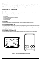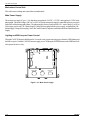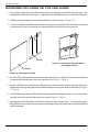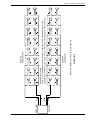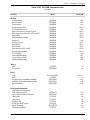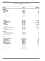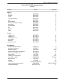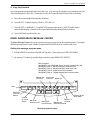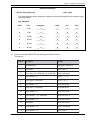
1
R
CD-100K
LASERSTAR
STARGLO
®
FIELD SERVICE MANUAL
& PARTS CATALOG
VOLUME 1 of 2
INSTALLATION, PROGRAMMING,
ROUTINE SERVICE
Part No. 21822666
Rev. C
CD-100K
®
LASERSTAR
STARGLO
FIELD SERVICE MANUAL & PARTS CATALOG
VOLUME 1
Rowe International, Inc.
1500 Union SE • Grand Rapids, MI 49507-1884
(616) 243-3633
Printed in USA
This page intentionally left blank.
ii
21822666
Preface
To make installation easier, this manual describes a typical installation. This “typical” installation only includes loading the
title rack and discs, setting up the sound system, and in some situations, modifying the pricing.
If you wish to make further programming changes, make them using the information that follows the basic installation.
This manual is divided into two parts. Volume 1 (Sections 1-3) contains routine installation and service information. Volume 2
(Sections 4-8) contains troubleshooting charts, schematics, and other maintenance information. Please take time to read this
page and review the Table of Contents in both volumes.
The Troubleshooting section includes schematics, component lists, and board layouts for all serviceable modules.
This service manual is divided into eight sections:
Volume 1
Section 1 System Description — Introduces you to the CD-100K, its features, and its major components, principles of
operation, and step-by-step unpacking instructions. After unpacking the CD-100K, you should continue the
installation process by following the title rack loading and programming instructions in Section 2.
Section 2 Installation and Programming — Continues the installation process with disc and title rack loading
instructions, programming references, and step-by-step programming and pricing instructions. Whether you are
familiar with previous Rowe phonographs or not, pay special attention to the pricing and programming.
Programming and pricing have been set at the factory, so you may not wish to change any of the CD-100K
options. After you load the titles and the discs, the CD-100K is ready to play.
Section 3 Routine Service — Provides routine service instructions for collecting money, doing cash and play audits,
resetting phonograph totals, and doing preventive maintenance.
Volume 2
Section 4 LED Lighting —
Section 5 Troubleshooting — Provides troubleshooting charts, error code and disc condition descriptions, troubleshooting procedures, wiring diagrams, and diagnostic LED descriptions.
Section 6 Mechanical Adjustments — Details the mechanical checks and adjustment procedures for all of the
CD-100K modules.
Section 7 Miscellaneous — Contains specifications, fuse and circuit breaker locations, and a resistor color code chart.
Section 8 The Parts Catalog — Lists and illustrates all replaceable modules in the CD-100K. The Accessory Equipment
List is at the end of this section.
This manual is intended for owners, route operators, and technicians. It provides all field and shop related service and
maintenance material. Accessories and their installation and service are discussed in the corresponding accessory
instructions (or manuals).
21822666
iii
Table of Contents
SECTION 1 — INSTALLATION AND SYSTEM DESCRIPTION
Introduction ......................................................................................................................................................... 1-1
Features .............................................................................................................................................................. 1-2
General Features ................................................................................................................................................ 1-2
Service Features ................................................................................................................................................. 1-2
Unpacking Instructions .......................................................................................................................................
Exterior ...............................................................................................................................................................
Doors .................................................................................................................................................................
Shipping Bolts, Clips, and Tape .........................................................................................................................
Title Page Assembly ...........................................................................................................................................
Mechanism .........................................................................................................................................................
CD Unpacking ................................................................................................................................................
1-3
1-3
1-3
1-4
1-4
1-5
1-5
Visual Inspection ................................................................................................................................................
Phonograph Leveling ........................................................................................................................................
Handy Case .........................................................................................................................................................
Warranty Registration Card ...............................................................................................................................
1-6
1-6
1-6
1-6
Major Components of the CD-100K ....................................................................................................................
CD Selection System ..........................................................................................................................................
Keyboard ...........................................................................................................................................................
Central Control Computer ....................................................................................................................................
Memorec ............................................................................................................................................................
Autoplay ............................................................................................................................................................
1-6
1-7
1-7
1-7
1-7
1-8
Principles of Operation ...................................................................................................................................... 1-8
Audio System ..................................................................................................................................................... 1-8
CD Player ....................................................................................................................................................... 1-8
Stereo Preamp ................................................................................................................................................ 1-8
Stereo Amplifier ................................................................................................................................................ 1-8
Two-Wire Volume Control ............................................................................................................................. 1-9
Output Transformers ........................................................................................................................................ 1-9
Speaker System ............................................................................................................................................. 1-9
CD Changer Mechanism .................................................................................................................................. 1-10
Magazine ..................................................................................................................................................... 1-10
Play Counter ................................................................................................................................................. 1-10
Money Counter ............................................................................................................................................. 1-10
Optical Switch ............................................................................................................................................... 1-10
Cam Switch and Motor Assembly ................................................................................................................. 1-11
Sprag Assembly ........................................................................................................................................... 1-11
CD Modules ................................................................................................................................................. 1-11
Mechanism Control Unit .................................................................................................................................... 1-12
Main Power Supply ......................................................................................................................................... 1-12
Lighting and Bill Acceptor Power Control ............................................................................................................ 1-12
SECTION 2 — INSTALLATION & PROGRAMMING
Introduction .........................................................................................................................................................
Power On ............................................................................................................................................................
Loading CD’s and Titles .....................................................................................................................................
Preparing Titles For The Title Holder .....................................................................................................................
Loading the Title Holder .......................................................................................................................................
iv
2-1
2-1
2-2
2-2
2-3
21822666
Table of Contents
SECTION 2 — INSTALLATION & PROGRAMMING (Continued)
Procedures for Loading the Title Page Holder ................................................................................................ 2-4
Procedures for Loading Discs ............................................................................................................................ 2-5
Setting Title Page Limits for the First Time ..................................................................................................... 2-7
Pricing ................................................................................................................................................................. 2-7
To Set Disc Prices .............................................................................................................................................. 2-8
How CD-100K Pricing Works .............................................................................................................................. 2-8
Sample Price Changes ................................................................................................................................... 2-8
Checking the Pricing ...................................................................................................................................... 2-10
Sound System Setup ........................................................................................................................................
Extension Speaker Operation ...........................................................................................................................
70-Volt Speakers ..............................................................................................................................................
Low Impedance Speakers ...............................................................................................................................
2-10
2-10
2-11
2-11
Selecting Speaker Power ................................................................................................................................
General Instructions ..........................................................................................................................................
Selection Procedures .........................................................................................................................................
4-Ohm Speakers ..........................................................................................................................................
8-Ohm Speakers ..........................................................................................................................................
70-Volt Speakers ..........................................................................................................................................
2-12
2-12
2-12
2-13
2-14
2-14
Transformer Wiring Diagram ...........................................................................................................................
Speaker Synopsis .............................................................................................................................................
IR Volume Control 2CH Preamp ......................................................................................................................
Single Volume Control Setup .............................................................................................................................
Dual Volume Control Setup ...............................................................................................................................
2-20
2-22
2-29
2-29
2-29
Sound System ...................................................................................................................................................
Acoustical Compensation (Equalizer Tone Controls) ..........................................................................................
What This Graphic Equalizer Does ...................................................................................................................
Equalizer Settings .............................................................................................................................................
If the Room or Speaker System Requires a Trade-Off .......................................................................................
Procedures for Adjustment .................................................................................................................................
Soft and Highly Absorbent Rooms ....................................................................................................................
Average or Moderately-Absorbent Rooms .........................................................................................................
Hard and Non-Absorbent Rooms ......................................................................................................................
Paging .............................................................................................................................................................
2-30
2-30
2-30
2-30
2-31
2-31
2-31
2-32
2-32
2-33
Changing the Number of Credits Remaining ................................................................................................. 2-33
Entering the Service Mode .............................................................................................................................. 2-33
Viewing Menus ................................................................................................................................................. 2-33
If You "Get Lost" in the Menus .......................................................................................................................... 2-34
Using CD-100K Commands ...............................................................................................................................
Combining Menu and Command Modes ...........................................................................................................
Service Mode Menu ..........................................................................................................................................
Security Menu ..................................................................................................................................................
Modem Menu ...................................................................................................................................................
Audits Menu .....................................................................................................................................................
Attract Mode Menu ...........................................................................................................................................
Message Center Menu .....................................................................................................................................
Initialize Menu ...................................................................................................................................................
Autoplay ..........................................................................................................................................................
Pricing Menu .....................................................................................................................................................
21822666
2-34
2-34
2-38
2-38
2-38
2-38
2-38
2-38
2-38
2-39
2-39
v
Table of Contents
SECTION 2 — INSTALLATION & PROGRAMMING (Continued)
Options Menu ..................................................................................................................................................
More Options 1 Menu .......................................................................................................................................
More Options 2 Menu .......................................................................................................................................
Reports Menu (Optional) ..................................................................................................................................
Status Menu ....................................................................................................................................................
Remote Menu (Optional) ..................................................................................................................................
2-39
2-40
2-40
2-40
2-40
2-40
How To Make Programming Changes ............................................................................................................
Keyboard Controls ............................................................................................................................................
Security Levels .................................................................................................................................................
Factory Security Level .......................................................................................................................................
Loading Factory Settings ...................................................................................................................................
2-41
2-41
2-42
2-42
2-42
Programming Autoplay, Premiums, Priorities, and Lockouts ......................................................................
Autoplay Programming Modes ........................................................................................................................
Lockout and Timed Lockout Modes ................................................................................................................
Editing Autoplay, Premiums, Priorities, and Lockouts ..................................................................................
2-76
2-77
2-78
2-78
Timed Free Play and Timed Lockout Scheduling Tutorial ........................................................................... 2-78
What Multiple Lockout On/Off Times Do ............................................................................................................ 2-78
What Multiple Freeplay On/Off Times Do .......................................................................................................... 2-78
Rowe Phonograph Message Center ...............................................................................................................
Inserting or Changing Messages .......................................................................................................................
Setting the Daily Message Display Time(s) .......................................................................................................
Setting the Master On/Off Date .........................................................................................................................
2-81
2-82
2-86
2-88
Enhanced Autoplay Tutorial ............................................................................................................................ 2-88
Autoplay .......................................................................................................................................................... 2-88
Differences Between Standard and Enhanced Autoplay ................................................................................... 2-88
Setting Up Enhanced Autoplay .......................................................................................................................
Using RESET + 9 in the Category Menu ...........................................................................................................
Disc Mode ....................................................................................................................................................
Category Mode .............................................................................................................................................
Day Of The Week ............................................................................................................................................
Event ...............................................................................................................................................................
Time .................................................................................................................................................................
Categories ........................................................................................................................................................
Delay ...............................................................................................................................................................
Channel 1 and Channel 2 Volume (Optional) ....................................................................................................
2-89
2-92
2-92
2-92
2-93
2-93
2-93
2-93
2-93
2-93
Working Example of Enhanced Autoplay ....................................................................................................... 2-94
Optional Studio Sound System ...................................................................................................................... 2-101
Introduction ................................................................................................................................................... 2-101
Volume Control Unit ..................................................................................................................................... 2-101
Audio/Video Controller ................................................................................................................................ 2-102
BGM, Autoplay, and Paid Play Volume ...................................................................................................... 2-102
Karaoke Controls .......................................................................................................................................... 2-102
Amplifier Factory Load ................................................................................................................................ 2-103
Other Configurations ........................................................................................................................................ 2-103
Summary of Audio/Video Controller Features and Flow – Front to Back ............................................................. 2-103
vi
21822666
Table of Contents
SECTION 3 — ROUTINE SERVICE
Introduction .........................................................................................................................................................
Doing an Audit ....................................................................................................................................................
Collecting Audit Figures ....................................................................................................................................
Entering the Service Mode ...................................................................................................................................
Cash Audits .......................................................................................................................................................
Play Audits .........................................................................................................................................................
Non-Resettable Audits ........................................................................................................................................
Most Popular Disc ..............................................................................................................................................
Least Popular Disc .............................................................................................................................................
Most Popular Selection .......................................................................................................................................
Clearing the Audit Values ....................................................................................................................................
Clear Cash .....................................................................................................................................................
Clear Plays .....................................................................................................................................................
Clear Selection Popularity ................................................................................................................................
3-1
3-1
3-1
3-1
3-2
3-2
3-2
3-2
3-2
3-3
3-3
3-3
3-3
3-3
Changing CD’s and Titles ................................................................................................................................... 3-4
Preparing Titles for the Title Holder ........................................................................................................................ 3-4
Changing Discs .................................................................................................................................................. 3-4
Complete Audit Command List ......................................................................................................................... 3-6
Collecting Money .............................................................................................................................................. 3-10
Preventive Maintenance .................................................................................................................................. 3-10
CD Player Laser Lens ...................................................................................................................................... 3-11
Coin Acceptors (Optional) ................................................................................................................................ 3-12
Coin Mech (Optional) ........................................................................................................................................ 3-12
FREQUENTLY USED FIGURES AND TABLES
Volume 1
Extension Speaker Worksheet (Table 2-1) ........................................................................................................... 2-12
Amplifier Overload Check (Table 2-2B) ................................................................................................................. 2-16
Speaker Connections (Figure 2-7) ................................................................................................................ 2-18, 2-19
Volume & Cancel Control Diagrams (Figure 2-8) ................................................................................................... 2-28
Service Mode Map (Figure 2-10) .......................................................................................................................... 2-36
Keyboard Controls (Table 2-4) ............................................................................................................................. 2-41
Menu and Command Descriptions (Table 2-5A and Table 2-5B) .......................................................................... 2-43
Command Index (Table 2-5) ................................................................................................................................ 2-69
Audit Commands (Table 3-1) ................................................................................................................................. 3-6
21822666
vii
Digital Display
Shows the Selection Playing,
Selection Being Made, Selections
Remaining, the Message Center,
and Service Mode Display
Selector Keyboard
Enters Numbers
Contains the POPULAR,
RESET, MY SONG FIRST,
and Page Turning Keys
Figure 1-1. CD-100K Major Components
viii
21822666
IMPORTANT SAFETY INSTRUCTIONS
1)
Read these instructions.
2)
Keep these instructions.
3)
Heed all warnings.
4)
Follow all instructions.
5)
Do not use this apparatus near water.
6)
Clean only with a dry cloth.
7) Do not block any ventilation openings. Install in
accordance with the manufacturer’s instructions.
10) Protect the power cord from being walked on
or pinched, particularly at plugs, convenience receptacles, and the point where they exit from the apparatus.
11) Only use the attachments/accessories specified
by the manufacturer.
12) Use only with the cart, stand,
tripod, bracket, or table specified by
the manufacturer or sold with the apparatus. When a cart is used, use
caution when moving the cart/apparatus combination to avoid injury from
tip-over.
8) Do not install near any heat sources such as
radiators, heat registers, stoves, or other apparatus 13) Unplug this apparatus during lightning storms or
(including amplifiers) that produce heat.
when unused for long periods of time.
9) Do not defeat the safety purpose of the polarized or grounding-type plug. A polarized plug has two
blades with one wider than the other. A grounding
type plug has two blades and a third grounding prong.
The wide blade or the third prong are provided for
your safety. If the provided plug does not fit into your
outlet, consult an electrician for replacement of the
obsolete outlet.
14) Refer all servicing to qualified service personnel. Servicing is required when the apparatus has
been damaged in any way, such as when the powersupply cord or plug is damaged, liquid has been
spilled or objects have fallen into the apparatus, the
apparatus has been exposed to rain or moisture, does
not operate normally, or has been dropped.
WARNING
Do not plug the phonograph in until you verify it is configured for the proper mains voltage.
61145001
Main Power Supply
Mains Supply
Voltage Selector Plug
1
2
3
4
BLACK
1
WHITE
2
WHITE
BLACK
3
120~
MAINS
SUPPLY
VOLTAGE
SELECTOR
4
BLUE
BLUE
240~
MAINS
SUPPLY
VOLTAGE
SELECTOR
CAUTION
RISK OF ELECTRIC SHOCK
DO NOT OPEN
CAUTION: TO REDUCE THE RISK OF ELECTRIC SHOCK, FIRE
HAZARD, AND PERSONAL INJURY;
NO OBJECTS FILLED WITH LIQUID, SUCH AS VASES, SHALL
BE PLACED ON THE APPARATUS.
DO NOT REMOVE ANY COVERS, GUARDS, OR SHIELDS.
NO USER SERVICEABLE PARTS ARE INSIDE THIS PHONOGRAPH.
REFER SERVICING TO QUALIFIED SERVICE PERSONNEL
The lightning flash with arrowhead symbol, within an equilateral triangle is intended to alert the user to the presence of
uninsulated “dangerous voltage” within the product’s enclosure that may be of sufficient magnitude to constitute a risk of
electric shock to persons.
The exclamation point within an equilateral triangle is intended
to alert the user to the presence of important operating and
maintenance (servicing instructions in the literature accompanying the phonograph).
Section 1: Installation & System Description
INTRODUCTION
The CD-100K plays compact discs exclusively. The reliable CD mechanism holds up to 100 compact discs. These
discs are played through a 1000 watt stereo amplifier.
Before you begin to unpack and use this phonograph, please pay special attention to the following:
READ THIS CAREFULLY BEFORE PLACING YOUR NEW PHONOGRAPH INTO SERVICE:
Mechanism - Completely unpack the mechanism before plugging in the AC
power line cord.
Title Pages - If you wish to turn the title pages manually, use the Title Page
Knob on the back of the title page assembly (see Figure 1-2).
CD Player - Read the CD player unpacking procedure and the static caution
that accompanies the procedure.
21822666
1-1
CD-100K Phonograph
FEATURES
The major CD-100K features are:
General Features:
• All lighting done with LED’s. No fluorescent or incandescent lamps used.
• LED lighting controllable by IR remote
• Sturdy construction and reliable design
• Conveniently located customer, operator, and service controls
• Message Center Display
• Electrically operated title pages
• Entire albums can be selected
• A 1000-watt (500 per channel) amplifier . Two-channel preamplifier with dual 7-band graphic equalizer.
• AVC keeps CD volume constant
• Volume controlled by IR remote and wired potentiometers
• 100 disc capacity
• As selected (FIFO) playback or random playback
• 500 bill capacity
• Attract mode to merchandise music or advertising with the use of the message center
• Many phonograph programming options
• Total of 50 selections may be “locked out”. Total of 100 selections may be “priorities”.
• Total of 30 selections may be “premium.” Premium can be 2, 3, 4, etc., standard credits.
• Real-time clock allows scheduling of Autoplay, Lockouts, Free Play, and Messages by time and day
• Accessories available to play background music and/or autoplay at different volume levels
• Timed alternate pricing
• “My Song First” feature to play a song ahead of songs previously selected
Service Features:
• All servicing can be done from the front of the phonograph
• Modular component construction for easy removal and replacement
• Alpha/Numeric display gives you more comprehensive readouts
• Complete cash and play audit information
• Three levels of security access provide limited access to route operators if desired
• Disc condition logging feature to help find skipping selections and unplayable discs
• Machine errors and disc conditions are logged by time and date
• Choice of 3 CD initialization procedures
• RS-232 interface allows you to print audit data, Memorec data, pricing options, disc conditions, and error
history
1-2
21822666
Section 1: Installation & System Description
UNPACKING INSTRUCTIONS
This section contains information for unpacking the phonograph and installing it on location. The phonograph is
shipped with all major components in place. Save all tie-down hardware in case the CD-100K must be moved to
another location.
Exterior
1. Remove the shipping carton with care: Do not use shipping hooks or sharp tools that could damage the
phonograph cabinet.
2. Remove the plastic bag that covers the phonograph.
3. Carefully inspect the interior and exterior of the phonograph to ensure that no damage occurred during transit.
If damage is detected, the carrier who delivered the phonograph should be contacted immediately to examine
it. Regardless of the exterior condition of the shipping cartons, the carrier should be called and notified of
damage. Do not destroy packing material or boxes until the carrier’s agent has examined them. Damage claims
are your responsibility. Do not return shipping-damaged merchandise until after your claim has been
established. Once your claim has been established, merchandise may be returned to your Rowe distributor
for repair. The invoice amount for repair charges can then be collected from the carrier.
Doors
Locate the red bag in the top hand hold on the back of the cabinet. Remove the door key from the bag and unlock
the top door. The lock is on the left side of the top door.
Shipping Bolts, Clips, and Tape
TITLE PAGE ASSEMBLY
See Next Page
221822666
1-3
CD-100K Phonograph
WARNING:
Do not attempt to turn the CD title pages by hand. Use the handwheel on the back of the
title page assembly (see Figure 1-2). Title rack will not operate without the two Shipping
Screws being removed. Trying to force movement in the Title rack can result in broken
parts.
Shipping Screw Locations
Title Page Knob
Plug Connection
Shipping Screws (2)
One on each side of Title Rack
View from the inside
of the Title Rack Plate
Title Page Assembly in the “UP” Position
Figure 1-2. Title Page
Title Page Assembly
1. Remove the shipping screws from both ends of the lower title page assembly support bracket.
2. Remove the shipping band from the front of the title page assembly.
3. Check to see if the title page assembly is plugged in (see Figure 1-2 above).
4. Remove (2) shipping screws from the back of the cabinet (toward the top) to allow title page assembly removal.
1-4
21822666
Section 1: Installation & System Description
Save all shipping hardware that you remove in the following six steps:
Mechanism
CD UNPACKING
1. Remove the CD changer mechanism shipping bolt from the back of the phonograph cabinet
(see Figure 1-3).
Figure 1-3. Shipping Bolt Removal
2. Remove the shipping tape from the front ends of the mechanism tie-down levers on the side of the mechanism
frame (see Figure 1-4).
3. Push the end of the lever down slightly, rotate the lever away from the frame until the latch tab clears the hole
in the frame, rotate the lever up until the mechanism is free, and remove the levers.
Tie-Down Bolt
Mechanism Frame
Figure 1-4. CD Changer Tie-Down Screws
221822666
1-5
CD-100K Phonograph
Do not proceed with unpacking until you read and understand the following caution:
CAUTION:
The CD mechanism is sensitive to static discharges. The photo diodes and the laser are
more sensitive to discharges than MOS IC’s. Careless handling may immediately destroy
components within the player or cause undetectable damage that will lead to failure
after several weeks or even months of use. Before you touch the player, discharge your
hands and tools by touching a grounded metal part of the phonograph, such as the
amplifier or power supply chassis. If you need to remove the CD player for servicing,
place the CD player into the anti-static bag (shipped with the phonograph for this
purpose) immediately after you remove it from the phonograph.
4.
5.
6.
7.
Remove the rubber band on the hold-down plate.
Remove the rubber band, wire hook, and warning tag that hold the sprag lever out of the sprag wheel.
Remove all tape from the magazine belt and magazine pulley.
Check to see that the title page assembly is plugged in.
VISUAL INSPECTION
Check to be sure that all electrical plugs are completely seated into their receptacles.
PHONOGRAPH LEVELING
To insure proper operation, level the phonograph cabinet from left-to-right and front-to-back by inserting spacers
under the caster wheels.
HANDY CASE
Locate the Handy Case in a blue plastic envelope. The Handy Case contains a variety of items, including the
phonograph service manual and parts catalog, spare parts, and fuses. Keep the Handy Case inside the phonograph
so the service manual and parts will be readily available when needed.
WARRANTY REGISTRATION CARD
A postage-paid Warranty Registration Card is included with the phonograph. This card should be filled out and
returned to Rowe.
MAJOR COMPONENTS OF THE CD-100K
Figure 1-1 shows the major components of the CD-100K Phonograph. Take a minute to familiarize yourself with
these components.
Table 8-1 (Volume 2, Section 8) lists the accessories that you may have in addition to the standard phonograph.
1-6
21822666
Section 1: Installation & System Description
CD Selection System
CD selections are made by entering the four-digit selection number on the selector keyboard (see Figure 1-5).
POPULAR
0
1
2
3
4
5
6
7
8
9
RESET
MY SONG
FIRST
Figure 1-5. Keyboard
Keyboard
The keyboard consists of 15 keys: Ten digit keys and five special keys. The two PAGE CHANGE keys move the
title pages electrically. The RESET button allows the customer to reenter his selection if he has changed his mind
or made a mistake. The POPULAR key selects the selection that customers have selected the greatest number of
times. Pressing the POPULAR key a second time will select the second most popular selection. Pressing the
POPULAR key a third time will select the third most popular selection and so on. The POPULAR key selection
feature can be disabled if desired - see Command 6994 in Table 2-4. The “My Song First” key allows a customer
to put his song (for extra credit) ahead of other songs that have been selected previously. See COMMAND 528
to disable this feature. See COMMAND 529 to set the number of credits to “Make My Song First”.
NOTE:
On a new phonograph, a phonograph that has had its CCC replaced, or a
phonograph that has had the POPULARITY cleared, the POPULAR key will
not select any disc number until at least one normal selection has been
made.
Central Control Computer
The central control computer (CCC) keeps track of all of the phonograph’s activities and determines what the various
components are to do next. The CCC regulates the following functions:
•
•
•
•
•
Calculating credit and making selections
Keeping track of selections not yet played
Calculating the most popular selection list
Remembering the operator’s programmed values
Storing and displaying the message center information
Memorec
Memorec is the part of the CCC that remembers the:
• Number of times each selection was played
• The total amount of money deposited in the phonograph
221822666
1-7
CD-100K Phonograph
Autoplay
When no selections have been made for a predetermined time, the Autoplay feature will play selections from a
programmed list or make random selections. The choice of which selections are chosen, the selection sequence,
and the selection interval can be programmed by the owner or service person.
PRINCIPLES OF OPERATION
Audio System
The audio system consists of the electronic components that transform the recorded sound into music.
The major components of the audio system are the:
•
•
•
•
CD Player
Stereo Preamplifier and Stereo Amplifier
Output Transformers
Speaker System
CD PLAYER
This subassembly translates digital pulses from the CD into a left and right channel audio signal.
STEREO PREAMP (Figure 1-6)
The preamp increases the signal from the CD player, corrects for varying recording levels (automatic volume control
or AVC), allows the volume to be adjusted manually, and modifies the CD tone (tone changes are made through
a 7-band graphic equalizer).
STEREO AMPLIFIER (Figure 1-6)
The power amplifier converts the preamp signal to a signal that can be used by the phonograph speakers.
Figure 1-6. 1000 Watt Stereo Amplifier Components
1-8
21822666
Section 1: Installation & System Description
Two-Wire Volume Control
A Rowe innovation, the two-wire volume control simplifies complex installations and reduces cost. A special
preamplifier design permits volume control wiring using any unshielded two-wire cable.
OUTPUT TRANSFORMERS
The output transformers (Figure 1-7) “step up” the power amplifier’s output voltage for 70-volt extension speakers.
The output transformers also provide connections (taps) for selecting different power levels for the speakers.
Figure 1-7. Output Transformer Package Components
SPEAKER SYSTEM
The speaker system consists of two specially designed speaker channels. Each channel consists of one woofer, one
mid/high range speaker, a tweeter, and a crossover network.
221822666
1-9
CD-100K Phonograph
CD Changer Mechanism
The CD changer mechanism, also referred to as the “mechanism” or “mech”, is located in the center of the cabinet’s
interior. It is the primary mechanical component of the phonograph. The mechanism holds 100 CD’s and plays
selections on command from the selection system. (Refer to Figure 1-8 for the location of each of the major
mechanism components.)
CD-Pro Plate &
Player Assembly
Mechanism
Control Assembly
Cancel
Switch
Money &
Play Counters
CD Magazine &
Retaining Belt
Cam Switch &
Motor Assembly
Gripper Bow &
Trunion Assembly
Optical Switch
Assembly
Sprag
Assembly
Mechanism Base
Figure 1-8. CD Changer Mechanism
MAGAZINE
The CD magazine stores 100 CD’s.
PLAY COUNTER
The play counter accumulates the total number of plays on the mechanism.
MONEY COUNTER
The money counter registers the total money deposited in the phonograph.
OPTICAL SWITCH
The optical switch senses the CD magazine position so that the CCC can determine which CD is in gripping position.
1-10
21822666
Section 1: Installation & System Description
CAM SWITCH AND MOTOR ASSEMBLY
The cam switch and motor assembly (see Figure 1-9) consists of the transfer motor, cam, and two cam
switches.
SPRAG ASSEMBLY
This assembly locks the CD magazine in position.
CD MODULES
The CD player plays the CD’s after they are positioned on the turntable by the disk transfer arm.
OUTER CAM SWITCH
Actuated in Disc
Playing Position
INNER CAM SWITCH
Actuated in Standby
Figure 1-9. Cam Switch & Motor Assembly
221822666
1-11
CD-100K Phonograph
Mechanism Control Unit
This solid-state switching unit controls the scan and transfer.
Main Power Supply
The main power supply (Figure 1-10) distributes unregulated +24 VDC, +12 VDC, and regulated +9 VDC to the
phonograph. The mains voltage (120 VAC or 240 VAC) to the main power supply is controlled by the power switch
on the back of the phonograph cabinet. The phonograph is factory configured for 120 ~ main voltage. For 220 to
240 voltage, remove the 120 ~ Mains Supply Voltage Selector plug from the power supply, and install the 240 ~
Mains Supply Voltage Selector plug. Note - the Central Control Computer is attached to the front of the Main Power
Supply.
Lighting and Bill Acceptor Power Control
When the CANCEL button is held down for 5 seconds, a relay opens removing power from the LED lighting and
the Bill Acceptor. Push the CANCEL button to apply power. Pushing the POWER button on the IR Remote will
also operate the above relay.
TRANSFORMER
POWER
LINE VOLTAGE
SELECT
Figure 1-10. Main Power Supply.
1-12
21822666
Section 2: Installation & Programming
Section 2: Installation & Programming
INTRODUCTION
This section describes the installation and programming process. This information begins with a summary of what
happens when the phonograph is powered up and continues with detailed instructions on how to load the titles and
discs, modify the pricing, and set up the sound system. The last part of this section describes how to make other
programming changes. (You can keep a record of the factory settings and your changes by using the Operator’s
Setup Sheet at the end of this section if you wish.)
POWER ON
WARNING
Do not plug the phonograph in until you verify it is configured for the proper mains voltage.
The phonograph is factory configured for 120 AC (~) mains voltage.
For 220 to 240 mains voltage, remove the 120 ~ Mains Supply Voltage Selector plug from the 61145001
Main Power Supply, and install the 240 ~ Main Supply Voltage Selector plug.
The 240 ~ Mains Supply Voltage Selector plug is factory shipped in the coin cash bag.
1
2
3
4
21822666
BLACK
1
WHITE
2
WHITE
BLACK
3
120~
MAINS
SUPPLY
VOLTAGE
SELECTOR
4
BLUE
BLUE
240~
MAINS
SUPPLY
VOLTAGE
SELECTOR
2-1
CD-100K Phonograph
The following steps are a summary of the detailed Power On Process that is described in Section 5 of Volume 2.
Step 1. Power switch on rear of phonograph is turned on, main power supply +9 VDC, +12 VDC, and
+24 VDC LED’s light, and all modules and components receive power. The 120~ relay closes,
supplying 120~ to the LED control and bill acceptor.
Step 2. The Voltage LED’s light on the CCC, mechanism control, KID controller, IR volume control, and title
display CBA. The Board Error LED’s on the CCC and mechanism control flash three times. The CCC
Rowelink Command, mechanism control and KID controller Rowelink TX, and IR volume control
Rowelink RCV LED’s continuously flicker.
Step 3. Phonograph is ready to operate.
CAUTION:
Do not attempt to turn the CD title pages by hand. If the title page assembly is unplugged
or not operating electronically, use the handwheel on the back of the assembly (see
Figure 1-2).
LOADING CD’S AND TITLES
The procedure for loading CD’s and titles into an empty phonograph is different from the procedure to change CD’s
and titles. Please make sure you are following the procedure that describes your situation.
Preparing Titles for the Title Holder
If your titles have not been shipped with the discs or preprinted, you will need to prepare the title strips yourself.
2-2
21822666
Section 2: Installation & Programming
Loading the Title Holder
All of the titles on the title strip sheet can be used for either right- or left-hand titles. If your title strips have not been
preprinted, you may want to type the titles before you tear the individual title strips off the title strip sheet.
Refer to the sample in Figure 2-1 for an illustration of where to tear the title strips off the title strip sheets.
These procedures describe how to load one CD album and one title strip. Repeat this procedure for each CD that
is being loaded.
Separate Here
TRACKING NO.
NEXT
2 DIGITS
DISC NO.
FIRST
2 DIGITS
TRACKING NO.
NEXT
2 DIGITS
01
01
02
02
03
03
04
04
05
05
06
06
07
07
08
08
09
09
10
10
11
11
12
12
13
13
14
14
ARTIST
ARTIST
DISC NO.
FIRST
2 DIGITS
Separate Here
TRACKING NO.
NEXT
2 DIGITS
DISC NO.
FIRST
2 DIGITS
TRACKING NO.
NEXT
2 DIGITS
01
01
02
02
03
03
04
04
05
05
06
06
07
07
08
08
09
09
10
10
11
11
12
12
13
13
14
14
ARTIST
ARTIST
DISC NO.
FIRST
2 DIGITS
Separate Here
BLANK TITLE STRIP - COMPACT DISC
Discard
Figure 2-1. Blank Title Sheet
21822666
2-3
CD-100K Phonograph
PROCEDURES FOR LOADING THE TITLE PAGE HOLDER
1. Tear each title strip from the title sheet so the perforated column appears on the side of the title strip. (The
shaded portion of the title strip in Figure 2-1 represents a title strip that has been removed from the title sheet).
2. Fold the title strip along the perforated line on both sides of the title strip (see Figure 2-2).
3. Locate the CD album booklet that matches the title strip you have just made. If the CD booklet is more than
two sheets thick, remove the inner sheets so that the booklet is no thicker than two title strips.
NO
C
DIS T
S
ITS
IG
C
.
FIR
2D
Tabs
A
B
Title Strip
Figure 2-3. Loading the Title Page Holder
(2 of 6 Pages Shown)
CD Booklet
Figure 2-2. Folding the Title Strip
4. Insert the CD booklet under the top and bottom tabs of the title page. Slide the CD booklet over until the it
is trapped by the molded stops on the title page holder (see Figure 2-3, Ref. A).
5. Insert the folded title strip under the top and bottom tabs of the title holder. Slide the title strip until the disc
number shows in the opening of the title strip and the title strip is locked in place by the molded stops (see Figure
2-3, Ref. B).
6. All of the tabs surrounding the CD booklet and title strip should be holding them in place. If you missed a tab,
carefully tuck the loose paper under the tab as shown in Figure 2-3, Ref. C.
7. Repeat Steps 4 and 5 until all titles are installed. Use the page keys switch (Figure 1-5) to change title pages.
Insert filler title strips to fill out any unused space left on a page. Insert these in the same way that you installed
the fill-in title strips.
2-4
21822666
Section 2: Installation & Programming
PROCEDURES FOR LOADING DISCS
Load discs as follows:
1. Unlock and open the top door.
2. Pull the SERVICE button out to the SERVICE position (refer
to Figure 2-4). The SERVICE switch is located in the upper
right-hand corner of the cabinet.
3. Press the CANCEL/SCAN button (located on the CD changer
mechanism) to move the disc space to the left or right of the
transfer arm.
4. Slide the CD into the slot with the label to the right.
Note that disc positions in the molded CD magazine are identified by numbers at every other slot, with even numbered slots
labeled on one half of the magazine and odd numbered slots
labeled on the other half.
Figure 2-4. Service Switch
For example, on the even numbered half of the magazine, slots
00, 04, and 08 are labeled, and the slots in between – 02 and
06 – are not, as illustrated in Figure 2-5.
NOTE:
When loading the magazine, make sure the disc rests in the same numbered slot in
both the front and rear of the magazine.
Slot 05
Odd Numbers
Slot 03
Slot 00
Slot 01
Slot 02
Slot 04
Even Numbers
Figure 2-5. Loading the Molded CD Magazine
21822666
2-5
CD-100K Phonograph
NOTE:
When loading discs, be sure to keep the magazine disc load approximately balanced.
If the magazine is partially loaded with all discs on one side, the sprag wheel may lock
and the magazine will not turn.
5. Check title strips and disc sequence to ensure that the titles and discs correspond.
6. After all titles and discs are in the proper places, perform a disc initialization. Initialization is performed in the
following manner:
NOTE:
You may wish to release the two catches that hold the display in place and lower the
keyboard/display.
A. Make sure that the phonograph is in the SERVICE mode and *SERVICE MODE* or
_ _ ERRORS EXIST _ _ appears on the display.
B.
Type 3 to select the INITIALIZE submenu and type 0. FULL INITIALIZE will appear on the display.
Press POPULAR to start the initialization and close the top door or place the phonograph in NORMAL
mode.
The initialization process will start and continue for approximately 30 minutes. During this time, the phonograph
can be used (see the notes that follow).
7. When initialization is finished, check that all discs have initialized. To do this, reenter the SERVICE mode and:
A. Type 3 to select the INITIALIZE submenu, and then type 4 to view the number of discs that have been
initialized. If this number does not match the number of discs that should have been initialized, do the
following step. If the number matches the number of discs that you expected to be initialized, initialization
is complete.
B. If the number of discs initialized does not match the number of discs that you expected to be initialized,
hold RESET and press 0 twice. This will place you in the DISC _ _ TRACK _ _ menu and display the
first disc and its number of selections. Hold RESET and press 3 to see the next disc and its number of
selections. Continue through the list by holding RESET and pressing 3 until you find a disc with the number
of tracks equal to 0 (zero). Continue through the disc list noting all discs with track numbers equal to 0.
C. Check that each disc on your list (ones with track numbers equal to 0) is in the proper slot, with the label
facing to the right. If it is not, move it to the proper slot. If the disc is in the proper slot, it may be defective.
Repair or replace it and do the individual disc initialization (see Changing Discs in Section 3).
2-6
21822666
Section 2: Installation & Programming
NOTE:
1. The initialization process will stop whenever the phonograph is in the SERVICE mode,
and will resume when the phonograph is returned to the NORMAL mode if the
phonograph is in Standby (i.e., no selections are in memory).
2. During full initialization, all disc limits are initially set to 99. As each disc is scanned,
the proper limits for that disc are stored in memory allowing only valid selections to
be made.
SETTING TITLE PAGE LIMITS FOR THE FIRST TIME
This procedure gives you specific instructions on how to set the page limits only.
The phonograph is shipped with all pages accessible. Pages 1 through 9 can be “flipped” and viewed. When you
install discs, you may not need all 9 pages. If you do not need all 9 pages, you should restrict page movement to
just those pages that have titles. Set the title page limits as follows:
1. Unlock and open the top door.
2. Pull the SERVICE button out to the SERVICE position (refer to Figure 2-4).
3. Make sure that *SERVICE MODE* or _ _ ERRORS EXIST _ _ appears on the display.
4. Type 2 to select the ATTRACT submenu then type 4 to select the PAGE LIMIT function and you will see
the display for entering the first page number to use and the last number to use. Press POPULAR, which sets
the first page number to 1. Notice that the blinking number has moved to the right. Type the last page number
to be used and press POPULAR. Flip the keyboard display back up, making sure that both catches are
engaged.
PRICING
The prices charged for CD selections may be changed as needed. When shipped from the factory, the prices are
set as follows:
PRICING:
PRICING:
2 plays for $1.00
5 plays for $2.00
15 plays for $5.00
plays for:
plays for:
plays for:
Figure 2-6A. Price Card
NOTE:
If you are using the factory pricing, skip to Sound System Set Up.
21822666
2-7
CD-100K Phonograph
To Set Disc Prices:
The Handy Case has a Price Card (see
Figure 2-6A) that may be substituted for the
Standard Price Card. The Handy Case also
contains a Price Sheet with printed prices
(see Figure 2-6B) which can be peeled off
and placed at the appropriate location on the
Price Card.
Using the phonograph keyboard, the pricing
structure of the phonograph may be adjusted
to match the prices on the Price Card. The
maximum amount that can be charged for a
selection is $99.95. The maximum number of
selections that can be entered is 999. The
POPULAR key must be pressed to record
the data entered on the display.
1 1 1
3 3 4
7 7 7
12 12 12
19 19 19
55 60 60
20P 20P
50P 50P
40¢ 40¢
$2.00 $2.00
£1.00 £1.00
Ä1.00 Ä1.00
Ä4.00 Ä4.00
5KR
1
4
7
13
19
1
4
8
13
19
20P
50P
50¢
$2.00
£1.00
Ä1.00
Ä4.00
1
4
8
13
20
20P
50P
50¢
$3.00
£1.00
Ä1.50
Ä5.00
1
4
8
13
20
20P
50P
50¢
$3.00
£1.00
Ä1.50
Ä5.00
1
4
8
13
20
1
4
8
14
20
20P
50P
60¢
$3.00
£1.50
Ä1.50
Ä5.00
1
4
9
14
20
20P
50P
60¢
$3.00
£1.50
Ä2.00
Ä5.00
2
4
9
14
21
2
4
9
14
21
30P
50P
60¢
$3.00
£1.50
Ä2.00
Ä5.00
2
5
9
14
21
30P
50P
80¢
$4.00
£1.50
Ä2.00
Ä5.00
2
5
9
15
25
2
5
10
15
25
30P
10¢
80¢
$4.00
£1.50
Ä2.00
Ä5.00
2
5
10
15
25
30P
10¢
80¢
$4.00
£2.00
Ä2.00
Ä5.00
2
5
10
15
30
30P
10¢
$1.00
$4.00
£2.00
Ä2.00
Ä5.00
2
5
10
15
30
2
5
10
16
30
2
5
10
16
35
3
5
11
16
35
3
5
11
16
40
30P 30P 40P
20¢ 20¢ 20¢
$1.00 $1.00 $1.00
$5.00 $5.00 $5.00
£2.00 £2.00 £2.00
Ä2.00 Ä2.00 Ä3.00
Ä10.00 Ä10.00 Ä10.00
3
6
11
16
40
40P
25¢
$1.00
$5.00
£2.00
Ä3.00
1KR
3
6
11
18
45
3
6
11
18
45
40P
25¢
$1.00
$5.00
£2.00
Ä3.00
1KR
3
6
11
18
50
40P
25¢
$2.00
£1.00
£2.00
Ä3.00
1KR
3
6
12
18
50
3
7
12
18
55
40P
40¢
$2.00
£1.00
Ä1.00
Ä4.00
5KR
ENGLISH:
FRENCH:
GERMAN:
INSTRUCTIONS:
IF SPECIAL PRICING IS REQUIRED, USE THE UNIVERSAL
PRICE SELECTION SHEET AND THE EXTRA PRICE CARD IN
THE HANDYCASE.
INSTRUCTIONS:
POUR PRIX SPECIAUX VEUILLEZ UTILISER LA FEUILLE
UNIVERSELLE DES PRIX DE SELECTION ET LA CARTE DE
PRIX SUPPLEMENTAIRE DANS LA POCHETTE.
INSTRUCTIONS:
FUER
SPEZIALPREISE
BITTE
DAS
ALLGEMEINE
PREISWAHLBLATT UND DIE EXTBA-PREISKARTE IN DER
MAPPE BENUETZEN.
1. PEEL DESIRED PRICING STRIP FROM THE SHEET AND
CAREFULLY LOCATE IT OVER THE APPROPRIATE COLOR
BAND (NUMBER OF SELECTIONS ON THE LEFT, PRICE OF
SELECTION ON THE RIGHT).
1. DECOLLEZ DE LA FEUILLE L'ETIQUETTE DE PRIX ET
PLACEZ LA SOIGNEUSEMENT SUR LA BANDE DE COULEUR
APPROPRIEE (NOMBRE DE SELECTIONS A GAUCHE, PRIX
DES SELECTIONS A DROITE).
1.
GEWUENSCHTER PREISSTREIFEN ABZIEHEN UND
VORSICHTIG UEBER DEN ZUGEHOERIGEN FARBSTREIFEN
PLATZIEREN (ANZAHL-WAHL LINKS, PREIS-WAHL RECHTS).
2. IF A PARTICULAR PRICING IS NOT WANTED, PEEL OFF
BLACK STRIPS AND CAREFULLY PLACE OVER PRICING
AND SELECTION NOT WANTED.
2.
SI UN PRIX PARTICULIER N'EST PAS DEMANDE,
DECOLLEX LES ETIQUETTES NEUTRES ET PLACEZ LES
SOIGNEUSEMENT SUR LES PRIX ET SELECTIONS NON
DESIRES.
2. WENN KEINE BESONDERE PREISE VERLANGT WERDEN,
NEUTRALE STREIFEN ABZIEHEN UND VORSICHTIG AUF DIE
PREIS UND WAHLANGABEN PLATZIEREN. DIE NICHT
ERWUENSCHT SIND.
61031403
Figure 2-6B. Universal Price Sheet
To set the pricing, follow the steps to complete the Price Card and enter the prices. Also, for your records, fill in
the Pricing section of the Rowe CD Phono Operator’s Set Up Sheet at the end of this section. Before making
the actual pricing changes, go through the sample pricing that follows.
How CD-100K Pricing Works
Pricing is determined by the numbers that are stored in the PRICE LEVELS and PLAYS @ LEVEL menus. The
LEVEL 1 PRICE corresponds to the LEVEL 1 PLAYS in the following way: Enough money must be deposited
to reach the first (#1) price level before any selections can be made. Once the amount of money matches this price,
the number of selections in the LEVEL 1 PLAYS menu can be made.
To make pricing changes, set the LEVEL 1 PRICE and LEVEL 1 PLAYS to match the lowest price and number
of plays on the Price Card. Then enter the remaining PRICE LEVELS and PLAYS @ LEVEL until you have set
all five levels. (If you do not have prices for all levels, enter 0’s in all of the remaining PRICE and PLAYS positions.)
SAMPLE PRICE CHANGES
1. Determine the prices that are to be charged for disc selections and place the price decals from the Price Sheet
into the slots on the Price Card. The following is an example of a completed Price Card:
Price of Selections
4 for $1.00
9 for $2.00
25 for $5.00
2. Enter the SERVICE mode by pulling the SERVICE button to the SERVICE position.
2-8
21822666
Section 2: Installation & Programming
NOTE:
This example will not give the correct dollar amounts for U.S. money unless PRICING
OPTION 3 is set to 5. (This is the factory setting for U.S. phonographs and you should
not have to change it.)
Use the prices in the example that follows to help yourself better understand the phonograph’s pricing.
Example CD Prices
4 for $1.00
9 for $2.00
25 for $5.00
If You Have a Problem in a Menu:
1. Press and hold down RESET and then press 0 until you come to the top of the current
menu.
2. If this menu name doesn’t help, press and hold RESET and then press POPULAR. This
will move you to the top of the previous menu. In most cases, this will return you to
the main menu (*SERVICE MODE*).
3. If you still cannot determine where you are, press and hold RESET and then press
POPULAR again. This will return you to the main menu (*SERVICE MODE*).
3. Select the PRICE LEVELS menu, Option 1, from the main menu by pressing 511.
4. Now enter the LEVEL 1 PRICE, which is the lowest disc selection price (enter 0100 and press POPULAR).
5. Move down to the next price (LEVEL 2 PRICE) by pressing and holding RESET and then pressing 1. Enter
the next highest price (enter 0200 and press POPULAR).
6. Move down to the next price (LEVEL 3 PRICE) by pressing and holding RESET and then pressing 1. Enter
the next highest price (enter 0500 and press POPULAR).
7. Move down to the next price (LEVEL 4 PRICE) by pressing and holding RESET and then pressing 1. Enter
0000 (because only three prices are being used) and press POPULAR.
8. Move down to the last price (LEVEL 5 PRICE) by pressing and holding RESET and then pressing 1. Enter
0000 and press POPULAR.
9. Press and hold RESET while pressing POPULAR 2 times. This will place you in the price menu. Select the
PLAYS @ LEVEL menu, Option 1, from the main menu by pressing 21.
10. Enter the number of disc selections to be given for the lowest amount on the disc portion of the example price
card into LEVEL 1 PLAYS (enter 004 and press POPULAR).
21822666
2-9
CD-100K Phonograph
11. Move down to the next play option (LEVEL 2 PLAYS) by pressing and holding RESET and then pressing
1 (enter 009 and press POPULAR).
12. Move down to the next play option (LEVEL 3 PLAYS) by pressing and holding RESET and then pressing
1 (enter 025 and press POPULAR).
13. Move down to the next play option (LEVEL 4 PLAYS) by pressing and holding RESET and then pressing
1 (enter 000 and press POPULAR).
14. Move down to the next play option (LEVEL 5 PLAYS) by pressing and holding RESET and then pressing
1 (enter 000 and press POPULAR).
CHECKING THE PRICING
Add bills (and coins, if a coin acceptor is installed) to reach the first (or next) price level. Check for proper credit
at each price level.
SOUND SYSTEM SETUP
If you are not using extension speakers, skip to Section 9 and setup the AUDIO EQUALIZERS.
Extension Speaker Operation
To avoid a poor sounding jukebox, care must be taken when adding extension speakers. Two requirements must
be met:
1. Speakers must be wired so that the power consumed by the jukebox speakers and extension speakers
does not exceed the amplifier power rating. After wiring the speakers, perform an Amplifier Overload
Check.
2. All speakers must be connected with the correct polarity.
NOTE:
Channel 1 output phase is reversed with respect to channel 2. This reversal is necessary
to extend monaural sound in a stereo jukebox system. Because of this reversal, speaker
connections to channel 1 must be reversed when compared to channel 2, except for 70 V
speaker connections. The 70 V phasing is reversed inside the output transformers. See
figure 3-7 for correct polarity hookup of extension speakers. If the (+) and (-) terminals
are not wired properly, the speakers will be out of phase, causing a reduction in low
frequencies (bass).
Several charts have been included to assist you with connection of the extension speakers.
Figure 3-7 shows the entire sound system.
2-10
21822666
Section 2: Installation & Programming
70-Volt Speakers
To avoid prohibitive cable losses on long speaker lines (over 100 feet), use 70 V speakers. The power level in the
70 V speakers is set at each speaker. 250 watts of the 1000 watts is provided for 70 V speakers by A1, A2
connections on the audio output transformer assembly.
NOTE: 1000 watts can be connected if you configure the amplifier for stereo and connect 70-volt speakers E7 to
E7.
Low Impedance Speakers
Low impedance speakers (8- or 4-ohm) can be used when the connecting cable is less than 100 feet.
4-OHM SPEAKERS
No more than one 4-ohm speaker should be connected to a speaker line. If several 4-ohm speakers are to be
used, each speaker should have its own line.
8-OHM SPEAKERS
The loss in 100 feet of 18 gauge zipcord feeding one 8-ohm speaker is 15%. The loss for two 8-ohm speakers is
30%.
NOTE:
In any speaker installation, the total speaker load (the sum of all power to all speakers)
must not exceed 1000 watts per amplifier. The phonograph has an audio output
transformer assembly rated 250 watts (125 per channel) for connecting 70 V speakers,
tapping down the phonograph speakers, or connecting extension speakers to taps. The
sum of all power to 70 V speakers and tapped speakers must not exceed 250 watts.
21822666
2-11
CD-100K Phonograph
Table 2-1 Extension Speaker Worksheet
Sheet 1
SELECTING SPEAKER POWER
General Instructions
This section will lead you through the power and speaker selection process. This process consists of four major steps
and several smaller steps. The major steps are:
1.
2.
3.
4.
Identifying the extension speakers and computing the extension speaker power.
Making the external speaker connections.
Determining and selecting the jukebox power (Jukebox speakers are 16 ohm).
Performing an amplifier overload check per table 3-2B.
Selection Procedures
1. Use a pencil (you may want to revise your figures) to fill in the work sheet on the following pages:
Extension speakers are available in these general categories: General purpose speakers (4 and 8 ohm speakers)
and 70 V speakers.
Use this worksheet to help you calculate the amount of power consumed by the extension speakers.
Use this worksheet as a guide to help you select which power tap to use for each type of external speaker you are
using. An extension speaker RMS power rating should be at least 10% higher than the power it will consume at max
phonograph volume.
When RMS power to speaker
at max phonograph volume is
250 watts
125 watts
62.5 watts
31.25 watts
Then recommended RMS power
rating of speaker is
300 watts
150 watts
75 watts
40 watts
Extension speakers connected to E1 - E7
Place the quantity of speakers in the blank under QTY and multiply the quantity times the power consumption (show
stereo speakers as 2 speakers). Place your results in the blank under TOTAL.
QTY
Total
Two 8 ohm speakers in series:
(31.25 watts to each speaker)
____at 62.5 watts per series =
____watts
Two 4 ohm speakers in series:
(62.5 watts to each speaker)
____at 125 watts per series =
____watts
8 ohm speakers:
____at 125 watts each =
____watts
4 ohm speakers:
____at 250 watts each =
____watts
2-12
21822666
Section 2: Installation & Programming
Table 2-1. Extension Speaker Worksheet
Sheet 2
4-OHM SPEAKERS CONNECTED TO TRANSFORMER TAPS
Place the quantity of speakers in the blank under QTY and multiply the quantity times the power consumption (show
stereo speakers as 2 speakers). Place your results in the blank under TOTAL.
4-Ohm Stereo Speakers connected to transformer taps
QTY
Total
Speakers for the 1 watt taps:
____at 1 watt each =
____watts
(E1 to E2)
Speakers for the 4 watt taps:
____at 4 watts each =
____watts
(E1 to E3)
Speakers for the 16 watt taps:
____at 16 watts each =
____watts
(E1 to E4)
Speakers for the 36 watt taps:
____at 36 watts each =
____watts
(E3 to E5)
Speakers for the 49 watt taps:
____at 49 watts each =
____watts
(E2 to E5)
Speakers for the 64 watt taps:
____at 64 watts each =
____watts
(E1 to E5)
Speakers for the 100 watt taps:
____at 100 watts each =
____watts
(E3 to E6)
Speakers for the 121 watt taps:
____at 121 watts each =
____watts
(E2 to E6)
Connections
4-Ohm Mono Speakers connected to transformer taps
Speakers for the 4 watt taps:
____at 4 watts each =
____watts
(E2 to E2)
Speakers for the 16 watt taps:
____at 16 watts each =
____watts
(E3 to E3)
Speakers for the 64 watt taps:
____at 64 watts each =
____watts
(E4 to E4)
Speakers for the 256 watt taps:
____at 256 watts each =
____watts
(E5 to E5)
21822666
2-13
CD-100K Phonograph
Table 2-1. Extension Speaker Worksheet
Sheet 3
8-OHM SPEAKERS CONNECTED TO TRANSFORMER TAPS
Place the quantity of speakers in the blank under QTY and multiply the quantity times the power consumption
(show stereo speakers as 2 speakers). Place your results in the blank under TOTAL.
8-Ohm Stereo Speakers connected to transformer taps
QTY
Total
Speakers for the .5 watt taps:
____at .5 watt each =
____watts
(E1 to E2)
Speakers for the 2 watt taps:
____at 2 watts each =
____watts
(E1 to E3)
Speakers for the 8 watt taps:
____at 8 watts each =
____watts
(E1 to E4)
Speakers for the 18 watt taps:
____at 18 watts each =
____watts
(E3 to E5)
Speakers for the 24 watt taps:
____at 24 watts each =
____watts
(E2 to E5)
Speakers for the 32 watt taps:
____at 32 watts each =
____watts
(E1 to E5)
Speakers for the 50 watt taps:
____at 50 watts each =
____watts
(E3 to E6)
Speakers for the 72 watt taps:
____at 72 watts each =
____watts
(E1 to E6)
Speakers for the 95 watt taps:
____at 95 watt each =
____watts
(E3 to E7)
Connections
8-Ohm Mono Speakers connected to transformer taps
Speakers for the 2 watt taps:
____at 2 watt each =
____watts
(E2 to E2)
Speakers for the 8 watt taps:
____at 8 watt each =
____watts
(E3 to E3)
Speakers for the 32 watt taps:
____at 32 watt each =
____watts
(E4 to E4)
Speakers for the 128 watt taps:
____at 128 watt each =
____watts
(E5 to E5)
70-VOLT SPEAKERS
70-volt speakers have a power tap on them or on their associated transformer. Add together all of the
70-volt speaker tap settings and enter that value:
____watts (A1 to A2)
____watts (E7 to E7)
2-14
21822666
Section 2: Installation & Programming
Table 2-1. Extension Speaker Worksheet
Sheet 4
Combine consumptions of all speakers:
Stereo
Mono
Connected to E1 - E7
______
______
Tapped 4-Ohm:
______
______
Tapped 8-Ohm
______
______
70-Volt A1, A2
______
______
70-Volt E7 to E7
Stereo
Totals:
______
Mono
__________ +__________
Subtract the Grand Total from 1000 and write the
result in the blank at the end of this line:
Sum of tapped
and A1, A2
70 Volt must
not exceed 250
Grand Total
= _____________
Power Available for the Phonograph___________
NOTE:
In any speaker installation, the total RMS speaker load (the sum of all power to all
speakers) must not exceed 1000 watts. It is strongly recommended that "Efficient"
extension speakers are used.
1. The Grand Total is the amount of power that the phonograph will need to supply to the extension speakers.
This amount must not exceed 1000 watts. If it is more than 1000 watts, you must reduce the power used by
the extension speakers to reduce the total power consumed, then recalculate the total power consumed.
When you subtract the Grand Total from 1000, you will get the "Power Available for the Phonograph"
figure. Be sure to write this value down in the blank because you will not be using it until you have wired all
of the extension speakers.
2. When you have reached a satisfactory combination of speakers and speaker power consumption, use the
CONNECTION column (the connections are in parentheses) as a wiring guide to make the actual
connection. The speaker terminal strips on the output transformer (refer to figure 1-1) are accessed by
removing the cover from rear of phonograph. Refer to figure 3-7 for typical examples of speaker
connections.
NOTE:
The amplifier may be connected to a load of 1000 watts before distortion will begin to
increase beyond specification.
21822666
2-15
CD-100K Phonograph
Table 2-1 Extension Speaker Worksheet
Sheet 4 (Continued)
3. The phonograph wires to change are the Violet (channel 1) and the Pink (channel 2) on the output
transformer assembly (see Table 3-2A).
Use Table 3-2A as a guide to select the power used by the phonograph. This power should roughly match
the amount indicated in "Power Available for the Phonograph" on the previous page.
Table 2-2A. Phonograph Speaker Power
Select the speaker taps that will use up most of the “Available Speaker Power”
You may select more or less phonograph power to suit your phonograph volume
preference.
Phono Power1
Phono Speaker Connections
1
Violet connects to Left E2, Pink Connects to Right E2
4
Violet connects to Left E3, Pink Connects to Right E3
16
Violet connects to Left E4, Pink Connects to Right E4
28
Violet connects to Left E5, Pink Connects to Right E5
64
Violet connects to Left E6, Pink Connects to Right E6
113
Violet connects to Left E7, Pink Connects to Right E7
Do not move the Black wire; it should stay on either the Left or Right E1 terminal.
Table 2-2B. Amplifier Overload Check
Check that the amplifier is not overloaded by performing the following four steps:
1. Make sure that the extension speakers are connected to the proper speaker taps.
2. Set the volume control to maximum volume and make a selection.
3. While the music is playing, if the OVERLOAD INDICATOR(S) stay OFF or occasionally flicker
in a random manner, the load is acceptable. If the OVERLOAD INDICATOR(S) are always lit
or flicker continuously, the amplifier is overloaded and will shut down, and you must perform
Step 4.
4. Do this step only if the OVERLOAD INDICATOR(S) came on as described in Step 3. Find the
source of the overload (shorted speaker wires, too many speakers connected, or speaker
power taps too high). After you fix the short, disconnect a few speakers or lower the speaker
power tap selection, then repeat Step 3.
1
This value is the total for both channels. The power consumption for each channel is one-half of this value.
2-16
21822666
Section 2: Installation & Programming
This page intentionally left blank.
21822666
2-17
CD-100K Phonograph
AUDIO OUTPUT
TRANSFORMER ASSEMBLY
E6
E5
16 V
E3
8V
4V
2V
0V
A1
A1
0V
2V
4V
31.63 V
PINK
1
BLACK
24 V
VIOLET
E5
E6
8V
16 V
E7
500 WATTS
PER CH
E4
CHANNEL 1
E3
E2
E1
A2
70V
70V MONO
1000 WATT
POWER AMP
70V
A2
E1
E2
500 WATTS
PER CH
24 V
E4
CHANNEL 2
E7
31.63 V
8
4
7
WOOFER
RT
JUKEBOX
SPEAKERS
WOOFER
+
+
LT
-
GREEN
BLACK
KEY
P2
7
3
6
5
5
2
4
3
SLATE
6
P1
PHONO
SPEAKER
CROSSOVER
2
1
W/G
KEY
W/O
O/B
W/BL
W/R
O/B
LT = CHANNEL 1
RT = CHANNEL 2
2-18
21822666
W/O
O/B
W/BL
O/B
21822666
4
6
8
5
-
W/G
3
-
1
RT
RT
LT
7
9
LT
+
MONAURAL
70 V SPEAKER
(24 WATTS)
MONAURAL
4 OHM SPEAKER
(4 WATTS)
+
MONAURAL
8 OHM SPEAKER
(8 WATTS)
+
Figure 2-7. Speaker Connections
NOTE:
POLARITY OF CHANNEL 1 E1 THRU E7 IS REVERSED
WITH RESPECT TO E1 THRU E7 OF CHANNEL 2
EXTENSION SPEAKERS
-
CHANNEL 2
70 V SPEAKER
(24 WATTS)
+
-
CHANNEL 2
4 OHM SPEAKER
(4 WATTS)
CHANNEL 2
8 OHM SPEAKER
(8 WATTS)
-
+
CHANNEL 1
8 OHM SPEAKER
(8 WATTS)
-
-
-
+
-
+
-
+
CHANNEL 1
70 V SPEAKER
(24 WATTS)
+
CHANNEL 1
4 OHM SPEAKER
(4 WATTS)
-
-
Section 2: Installation & Programming
+
HIGH FREQUENCY
2
+
MID RANGE
+
HIGH FREQUENCY
W/R
+
MID RANGE
JUKEBOX DOOR
SPEAKERS
2-19
-
CD-100K Phonograph
Y
E7
BR
E6
G
E5
BR/W
E4
G/W
E3
BL/W
E2
B
E1
B/W
A1
S
A2
S
A1
B/W
A2
B
E1
BL/W
E2
CHANNEL 2 OR 4
G/W
E3
BR/W
E4
G
E5
BR
E6
Y
BR
B/W
G
B
E7
2 1
CHANNEL 1 OR 3
1 2
40832108 TRANSFORMER WIRING DIAGRAM
2-20
21822666
Section 2: Installation & Programming
This page intentionally left blank.
21822666
2-21
CD-100K Phonograph
SPEAKER SYNOPSIS
1000 WATTS OF RMS POWER PER AMPLIFIER OR 500 WATTS PER CHANNEL.
The generic speaker wiring diagrams cover 4 to 32 speakers. Diagram 1 has a 4 speaker layout. If you only want
the four speaker layout, then the maximum output of each speaker would have to be rated 4 ohms and capable of
300 watts.
Question: Why a 300 watt rating on the speaker?
Answer: Safety factor/life of speaker.
These speakers are expensive, providing a lot of sound in a localized area which does not optimize the room sound.
A better way to distribute the sound is by adding more speakers. Diagram 2 has a layout of 8 speakers at 8 ohms
each and only having a rating of 150 watts each, which includes a safety factor. The expense factor should now be
less for each speaker.
For a really big room, Diagram 3 may be the best scenario. Diagram 3 shows a series/parallel hookup with up to
16 speakers. The advantage is the ratings are 4 ohms at only 75 watts each. Thus giving you a lot of sound at a
reasonable price. To ensure the speakers work correctly, the 2 wired in series should be of the same make and
model. Different models wired in series will not give equal outputs, and the frequency response may be strange.
Question: Too many speakers now?
Answer: Simply leave off as many speakers as you wish, as long as it is 2 at a time, which means a series combo
combination.
To minimize cost, it is recommended to utilize Diagram 4. This shows 32 speakers, their rating only has to be 8 ohms
at 50 watts. This allows you to use inexpensive speakers which can be found at the big electronic stores. This also
provides you the chance to A/B them for sound. Try also to get the most efficient speakers.
2-22
21822666
21822666
Amplifier
1000 watts
Amplifier
1000 watts
E1
E1
E1
E1
E7
E7
E7
E7
DIAGRAM 2
Speakers
Right Channel
Speakers
Left Channel
Eight 8 ohm speakers each rated at a minimum of
150 watts each. (Note: Left channel is out of phase,
plus + and minus -, in hookup with respect to right channel)
Speakers
Left Channel
Four 4 ohm speakers each rated at a minimum of
300 watts each. (Note: Left channel is out of phase,
plus + and minus -, in hookup with respect to right
channel)
Speakers
Right Channel
EACH SPEAKER OUTPUT IS 125 WATTS
DIAGRAM 1
EACH SPEAKER OUTPUT IS 250 WATTS
Section 2: Installation & Programming
2-23
2-24
Amplifier
1000 watts
E7
E1
E7
E1
DIAGRAM 3
EACH SPEAKER OUTPUT IS 62.5 WATTS
Speakers
Left Channel
Series/Parall Hookup
Sixteen 4 ohm speakers each rated at a minimum of 75 watts each (Note: Left
channel is out of phase, plus + and minus -, in hookup with respect to right channel).
Speakers
Right Channel
CD-100K Phonograph
21822666
21822666
Amplifier
1000 watts
E7
E1
E7
E1
DIAGRAM 4
EACH SPEAKER OUTPUT IS 31.25 WATTS
Speakers
Left Channel
Series/Parall Hookup
Thirty two 8 ohm speakers each rated at a minimum of 50 watts each (Note: Left
channel is out of phase, plus + and minus -, in hookup with respect to right channel).
Speakers
Right Channel
Section 2: Installation & Programming
2-25
2-26
Amplifier
E6
E6
E1
E1
E7
E1
E7
Violet
Pink
Black
Speakers
Left Channel
Speakers
Right Channel
Pink and Violet connect to E6 as shown
Black connects to E1
Jukebox
Internal
Speakers
1000 watts
Second
Amplifier
External
Only
1000 watts
Speakers
Left Channel
Speakers
Right Channel
CD-100K Phonograph
21822666
Section 2: Installation & Programming
This page intentionally left blank.
21822666
2-27
CD-100K Phonograph
ORDER ROWE
CABLE 20819908
W
B
R
G
B
W
B
R
G
VOLUME
COMMON
CANCEL
Dual Remote Volume &
Cancel Control 30632209
ORDER ROWE
CABLE 20819907
W
W
B
B
R
R
B
VOLUME
COMMON
CANCEL
Dual Remote Volume &
Cancel Contro 30632201
Figure 2-8A. Remote Volume Control Diagrams
2-28
21822666
Section 2: Installation & Programming
IR VOLUME CONTROL 2CH PREAMP
Volume can be controlled by a 21958307 IR transmitter and a single- or dual-wired remote control.
When the wired volume control is moved, the volume will quickly fade up or down to match its position. When moving
a wired remote control, it is best to quickly turn the volume off then turn it up to the desired volume. This will eliminate
a sudden loud blast if the wired remote control was set at or close to full volume.
The IR transmitter Ch1+, Ch2+, Ch1-, Ch2- keys will raise and lower the volume.
The ROWELINK RCB LED should flash continuously at approximated 20 CPS.
The IR VOL COMM LED will flash when a Ch1+, Ch2+, Ch1-, Ch2- key is pushed.
Single Volume Control Setup
• Set terminal block jumper as shown in Figure 2-8A Remote Volume & Cancel Control 30632201.
• On 40933101 set all S1 DIP switches to OFF (refer to Figure 2-8B).
• On 40933101 plug connector into P2. P1 is left open.
Dual Volume Control Setup
• Set terminal block jumper as shown in Figure 2-8A Dual Remote Volume & Cancel Control 30632209.
• On 40933101 set S1-1 DIP switch to ON and all others OFF (refer to Figure 2-8B).
• On 40933101 plug connector into P1. P2 is left open.
40933101 IR VOLUME CONTROL 2CH PREAMP
ROWELINK
Figure 2-8B. IR Volume Control 2CH Preamp
21822666
2-29
CD-100K Phonograph
SOUND SYSTEM
Acoustical Compensation (Equalizer Tone Controls)
The preamplifier contains seven tone controls on each channel to compensate for room acoustics in various locations.
These controls are on the amplifier chassis. The sound level at which the phonograph will be operated and the room
furnishings determine the settings of these controls.
A room with carpet and drapery is a soft or highly absorbent location. A crowded room is also highly absorbent.
These location require greater emphasis of high frequencies.
A room with paneled walls and a bare or tiled floor is a hard, nonabsorbent location, which requires greater low
frequency emphasis.
Regardless of the room acoustics, the high and low frequency characteristics of your speakers can influence the
equalizer settings as much or more than the room acoustics.
What This Graphic Equalizer Does
This graphic equalizer controls the tone for seven specific tone ranges. The frequency for each range is printed next
to each equalizer control.
IMPORTANT:
+ Before setting these controls, do Steps 1-5 in Table 2-2B to ensure that the amplifier is
not overloaded.
+ Each of these controls can limit the maximum volume for its range by as much as 85%.
+ This means that if a control is set to minimum, that the maximum power available for
that range is only about 40 watts.
+ If all of the graphic equalizer controls are set to minimum, then the phonograph will
produce no more than approximately 40 watts of its 250 watt capacity.
Equalizer Settings
These equalizers work equally well for stereo and mono sound and may be used with single and dual volume controls.
The settings that follow will give a good sound for a room with the matching acoustics (highly absorbent, moderately
absorbent, nonabsorbent). Set the right and left channel equalizer controls to the positions that match the room
described (or most closely described) in the three illustrations that follow this paragraph. These settings may be just
right or they may not sound 100% right to you. If the sound is not satisfactory, make small changes in the settings
until the sound is just the way you want it.
2-30
21822666
Section 2: Installation & Programming
If the Room or Speaker System Requires a Trade-Off
The equalizer limits the volume of all of the audio frequencies. Therefore, to achieve the best sound for a specific
room or set of speakers, you may find that most of the graphic equalizer controls need to be turned down. In this
situation, the overall phonograph volume may not be adequate. If you find that you have this situation, increase each
graphic equalizer control slightly until the phonograph produces the required volume.
Procedures for Adjustment
Select one of the Room Acoustics that most closely matches the acoustics of your room and follow the instructions
for that room type. If your room is an average or moderately absorbent room, or you like the sound of the
phonograph, you can use the factory settings just the way they are.
Soft and Highly Absorbent Rooms
Rooms with carpet and drapery are considered to be “soft and
highly absorbent.”
1. Turn all seven right channel and seven left channel graphic
equalizer controls fully counterclockwise.
GRAPHIC EQUALIZER
RIGHT CHANNEL
15.8KHZ
0
343HZ
0
108HZ
0
10.8KHZ
3.43KHZ
0
MUSIC LEVEL
DURING PAGING
0
H
2. Turn the 46 and the 108 Hz controls to the position
midway between the maximum and the minimum position
as shown to the right. Leave all of the other controls turned
all the way counterclockwise.
46HZ
L
1.08KHZ
0
0
CD INPUT
STEREO
MICROPHONE
INPUT
AVC ON
IN
OUT
GROUND
OUT
IN
3. The controls on the equalizer should now be set as shown
to the right.
13
AUX
AVC OFF
MONO
1
CD INPUT
4. Play a selection and turn the controls slightly (no more than
1/8 of a turn at a time) until the sound is acceptable. Be sure
that the phonograph volume is adequate. If the volume is
not adequate, turn each control up (counterclockwise)
slightly until the volume is satisfactory.
Remember: The maximum volume setting is obtained
when all controls are turned full counterclockwise.
46HZ
108HZ
343HZ
0
0
0
1.08KHZ
3.43KHZ
10.8KHZ
0
0
VOLUME
CONTROL
0
LEFT CHANNEL
GRAPHIC EQUALIZER
15.8KHZ
1183S
Figure 2-9A. “Soft” Rooms
21822666
2-31
CD-100K Phonograph
Average or Moderately Absorbent Rooms
GRAPHIC EQUALIZER
RIGHT CHANNEL
15.8KHZ
0
These are the factory settings.
1. Turn all seven right channel and seven left channel graphic
equalizer controls fully counterclockwise.
343HZ
0
108HZ
0
3. Play a selection and turn the controls slightly (no more than
1/8 of a turn at a time) until the sound is acceptable. Be sure
that the phonograph volume is adequate. If the volume is
not adequate, you will need to turn each control up
(counterclockwise) slightly until the volume is satisfactory.
3.43KHZ
0
MUSIC LEVEL
DURING PAGING
0
H
46HZ
2. The graphic equalizer’s controls should now be set as
shown to the right.
10.8KHZ
L
1.08KHZ
0
0
CD INPUT
STEREO
13
MICROPHONE
INPUT
AVC ON
IN
OUT
GROUND
OUT
IN
AUX
AVC OFF
MONO
1
CD INPUT
Remember: The maximum volume setting is obtained
when all controls are turned full counterclockwise.
46HZ
108HZ
343HZ
0
0
0
1.08KHZ
3.43KHZ
10.8KHZ
0
VOLUME
CONTROL
0
0
LEFT CHANNEL
GRAPHIC EQUALIZER
15.8KHZ
1183A
Figure 2-9B. “Average” Rooms
Hard or Non-Absorbent Rooms
Rooms that are paneled and have bare or tiled floors are
considered to be “hard or nonabsorbent.”
1. Turn all seven right channel and seven left channel graphic
equalizer controls fully counterclockwise.
2. Turn the 15.8 kHz control all the way clockwise as shown
to the right.
3. Turn the 10.8 kHz control to the position midway between
the maximum and minimum position as shown to the right.
Leave the 46 Hz, 108 Hz, 343 Hz, 1.08 kHz, and 3.43
kHz controls turned all the way counterclockwise.
4. The controls on the equalizer should now be set as shown
to the right.
5. Play a selection and turn the controls slightly (no more than
1/8 of a turn at a time) until the sound is acceptable. Be sure
that the phonograph volume is adequate. If the volume is
not adequate, you will need to turn each control up
(counterclockwise) slightly until the volume is satisfactory.
Remember: The maximum volume setting is obtained
when all controls are turned full counterclockwise.
GRAPHIC EQUALIZER
RIGHT CHANNEL
15.8KHZ
0
343HZ
0
108HZ
0
10.8KHZ
3.43KHZ
0
MUSIC LEVEL
DURING PAGING
0
H
46HZ
L
1.08KHZ
0
0
CD INPUT
STEREO
MICROPHONE
INPUT
AVC ON
IN
OUT
GROUND
OUT
IN
13
AUX
AVC OFF
MONO
1
CD INPUT
46HZ
108HZ
343HZ
0
0
0
1.08KHZ
3.43KHZ
10.8KHZ
0
0
VOLUME
CONTROL
0
LEFT CHANNEL
GRAPHIC EQUALIZER
15.8KHZ
1183N
Figure 2-9C. “Non-Absorbent” Rooms
2-32
21822666
Section 2: Installation & Programming
Paging
Paging circuitry is part of the Preamplifier. The Microphone cable plugs directly into the preamplifier.
NOTE:
Basic installation and setup are now completed and the CD-100K is ready for your
customer.
The remainder of Section 2 explains the Service Mode and other programmable features
of the CD-100K.
Use the procedure that follows to clear or change remaining credits.
CHANGING THE NUMBER OF CREDITS REMAINING
Use these steps to increase or decrease the number of CREDITS REMAINING on the phonograph.
1. Enter the SERVICE mode by pulling the SERVICE button out to the SERVICE position.
2. Type 84, then type the number of CREDITS REMAINING that you want. Press POPULAR to complete
the change.
ENTERING THE SERVICE MODE
Menus can only be used while the phonograph is in the SERVICE mode. To enter the SERVICE mode, open the
top door and pull the SERVICE button out (Figure 2-4) to the SERVICE position.
When the phonograph is placed into the SERVICE mode, the message *SERVICE MODE* appears on the digital
display (see Figure 1-1 if you are not familiar with the keyboard or display).
Occasionally, the message that first appears will say - ERRORS EXIST -. This is just an indication that a error has
been logged. Pushing the POPULAR key will return the *SERVICE MODE* message.
NOTE:
The phonograph’s display can display a maximum of 16 characters at a time. SERVICE mode commands and messages are abbreviated to fit the 16-character space.
VIEWING MENUS
To view a menu option, hold down the RESET button and press either the 0 digit or the 1 digit. The 1 digit will scroll
down one item and the 0 will scroll up one item. This method of viewing menu options will allow you to view your
options in any menu (or submenu). Refer to Figure 2-10, The Service Mode Map, and note that an arrow following
the indicates that a submenu exists. Press the POPULAR key to enter a submenu. Hold the RESET key and press
the POPULAR key to exit a submenu.
21822666
2-33
CD-100K Phonograph
If You “Get Lost” in the Menus
Since the menu mode of pricing and programming does not require you to use any reference material, you may
(occasionally) find that you have ventured down the wrong menu and that you don’t know what option is next. To
correct this situation, perform the following steps:
1. Press and hold down RESET and press 0 until you come to the top of current menu.
2. If this menu name doesn’t help, press and hold RESET and press POPULAR. This will move you to the top
of the previous menu. In most cases, this will return you to the main menu ( * SERVICE MODE * ).
3. If you still cannot determine where you are, press and hold RESET and press POPULAR again. Repeat this
step until you get to the main menu ( * SERVICE MODE * ).
USING CD-100K COMMANDS
CD-100K commands are formed by combining the numbers that appear on the left side of the menus in Figure 2-10.
To construct and use CD-100K commands, refer to Figure 2-10 or Table 2-4.
Example: You want to view the number of cycles the CD mechanism has made. Using Figure 2-10, you determine
that you need to select AUDITS (1) on the main menu; NON-RESETTABLES (2) on the AUDIT
menu; and MECH (7) on the NON-RESETTABLES menu. Use the digits to form a numeric command,
which is 127. Type 127 and the number of mechanism cycles is displayed.
NOTE:
To use the command mode effectively, return to the main menu after each command is
completed. Do this by holding RESET down and pressing POPULAR until the words
*SERVICE MODE* appear on the digital display.
Combining Menu and Modes
The most efficient way to set pricing and change programming is to use a combination of the menu mode and the
command mode to move through the menus. To do this, use the command mode to get to the command you want
to use, execute the command, and use the menu mode to go to your next selection.
2-34
21822666
Section 2: Installation & Programming
This page intentionally left blank.
21822666
2-35
CD-100K Phonograph
*SERVICE MODE*
CD SERIES
SERVICE
MODE
MAP
0
1
2
3
4
5
6
7
8
9
0-
*SECURITY*
08-
0
1
2
3
4
5
6
7
8
9
ENTER CODE ---SECURITY LEVEL LVL 2 CODE ---LVL 3 CODE ---PHONO ID ---VOID SRVC SW --SECURITY IS ---
0
1
2
3
4
5
6
7
8
9
20
1
2
3
4
5
6
7
8
9
MODEM ---------->
*ATTRACT*
ATTRACT MODE ---PAGE MODE --CHANGE TIME -DISPLAY PAGE PAGE IN -OUTSPEED IN -OUTSLED RESET --MESSAGE CENTER ->
PIEZO TIME --PLAY DELAY --
*MESSAGE CENTER*
10
1
2
3
4
5
6
7
8
9
*INITIALIZE*
40
1
2
3
4
5
6
7
8
9
*PRICING*
50-
FREE SCH SMTWTFS
COUNTRY =
0
1
2
3
4
5
6
7
8
9
MSG SCH SMTWTFS
1 ON 01 01 1980
MSG 1 EDT DEL VU
SCROLL MESSAGE
4 HOUR CLEAR -- ----
FULL INITIALIZE
PROGRAM INIT -DISC-- TRACK-CANCEL INIT
INITIALIZED -CONDITION LOG -SKIP CANCEL -TIME CANCEL -TIME --:--:-DATE --/--/----
COIN SW VALUES -->
PRICE LEVELS ----->
PLAYS @ LEVEL --->
MULTIPLIER -TIMED FPLAY --FPLAY STATUS --SHORT PULSES ---
089-
0
1
2
3
4
5
6
7
8
9
0
1
2
3
4
5
6
7
8
9
0
1
2
3
4
5
6
7
8
9
*MODEM*
MODEM PW -----ANSWER ON --:-ANSWER OFF --:-# OF RINGS MODEM RECV --CONNECT DELAY
MODEM XMT INIT
MODEM RCV INIT
RESTORE FACT INIT
MODEM SPECIAL ->
27-
3-
5-
SECURITY ---------->
AUDITS -------------->
ATTRACT ----------->
INITIALIZE ---------->
AUTOPLAY --------->
PRICING ------------->
OPTIONS ------------>
REPORTS ----------->
STATUS -------------->
DEVICE SETUP ---->
0
1
2
3
4
5
6
7
8
9
DISC-- START-VIDEO CD'S ---
*AUTOPLAY*
AUTOPLAY IS --DELAY TIME -START TIME --:-STOP TIME --:-ON DAYS SMTWTFS
PROGRAM -----CLEAR PROGRAMMED
APLAY STATUS ---XX CAT --------SCHEDULE SMTWTFS
*COIN SW VALUES*
COIN SW 1 --COIN SW 2 --COIN SW 3 --COIN SW 4 --COIN SW 5 --COIN/BILL 6 -BILL 1
--BILL 2
--COIN/BILL 6 ----
120
1
2
3
4
5
6
7
8
9
*MODEM SPECIAL*
MODEM POST --DAYS ACT SMTWTFS
POST ON --:-POST OFF --:-POST TELEPHONE #
RETRIES -MODEM PAGE --PAGE TO POST --PAGE TELEPHONE #
PAGE SUFFIX
*AUDITS*
CASH AUDITS ---->
PLAY AUDITS ---->
NON-RESETTABLES ->
CLEAR DISC POP
CLEAR CASH
CLEAR PLAYS
CLEAR SEL POP
MP DISC --- = --LP DISC --- = --MP SEL ---- = ----
*NON-RESETTABLES*
-CASH
-BILL
-COIN
-WBOX
FREE
PAID
MPOP
MECH
ALBUM
SELS
-----------------------------------------------------------------------
51- *PRICE LEVELS*
0
1
2
3
4
5
6
7
8
9
LVL 1 PRICE
LVL 2 PRICE
LVL 3 PRICE
LVL 4 PRICE
LVL 5 PRICE
-----------
10-
*CASH AUDITS*
0
1
2
3
4
5
6
7
8
9
CASH = --------------BILL = ---------------COIN = ---------------WBOX = ---------------COIN TOTALS ---->
1040
1
2
3
4
5
6
7
8
9
110
1
2
3
4
5
6
7
8
9
520
1
2
3
4
5
6
7
8
9
1 BILLS
2 BILLS
-------
COIN TOTALS
1 COINS
2 COINS
3 COINS
4 COINS
5 COINS
6 COINS
-------------------
*PLAY AUDITS*
FREE CRDTS ----PAID CRDTS ----AUTOPLAYS ----MECH PLAYS ----ALBUM SELS ----MPOP SELS ----NORM SELS ----OVERPLAY ----MSF SELS ----
*PLAYS @ LEVEL*
LVL 1 PLAYS --LVL 2 PLAYS --LVL 3 PLAYS --LVL 4 PLAYS --LVL 5 PLAYS --ALT PRC ON --:-ALT PRC OFF --:-MY SNG FIRST --MSF CREDITS --
Version 2.3
KEY FUNCTIONS
RESET + 0 ----> Move up 1 line
RESET + 1 ----> Move down 1 line
RESET + 2 ----> Move left, decrement
RESET + 3 ----> Move right, increment
RESET + 4 ----> Delete
RESET + 5 ----> Insert
RESET + 7 ----> Negate
RESET + 8 ----> Copy
RESET + 9 ----> Toggle/Next
RESET + POPULAR ----> Escape/Backup
POPULAR ----> Enter
NOTE: A line beginning with an * is the
title of a page. A line ending with ----->
indicates another page exists.
Figure 2-10. Service Mode Map
2-36
21822666
Section 2: Installation & Programming
60
1
2
3
4
5
6
7
8
9
70
1
2
3
4
5
6
7
8
9
*OPTIONS*
LOCKOUTS -- ---PRIORITY -- ---PREMIUMS -- ---KEEP CREDIT --KEEP MONEY --ALBUM SELECT --PRIORITY PLY --TRKS IN A ROW -KARAOKE
MORE OPTIONS 1 --->
*REPORTS*
CASH REPORT
PLAY REPORT
POPULAR REPORT
NON RESET REPORT
ALL AUDIT REPORT
SETUP REPORT
ERR HIST REPORT
DISC COND REPORT
BAUD RATE ---CANCEL REPORTS
69- *MORE OPTIONS*
699-
*MORE OPTIONS 2*
PAID PLAY ---FREE PLAY ---CLEAR TIME --LOCKOUT COUNT -PLAY LIMIT --CANCEL APLAY --AP ONLY -- ---DAYLIT IS -----AUTOMAT CLR --MORE OPTIONS 2 --->
0
1
2
3
4
5
6
7
8
9
TIM LOCK -- ---LOCK SCH SMTWTFS
FREE ALBUM --THANK YOU --POPULAR KEY --PREMIUM RATIO -AUTOLOD DFLT --RAM TEST CODE SEL ---- --:-PAIRS SEL ----
0
1
2
3
4
5
6
7
8
9
80
1
2
3
4
5
6
7
8
9
9- *DEVICE SETUP*
90-
AMPLIFIER ---------->
IR REMOTE ---------->
MAIN DISP LINE
BGM DELAY TIME -LEAD SINGER ----AMP FACTORY LOAD
APLAY VOLUME -----VOLUME OPTION
VOLUME STEP
0
1
2
3
4
5
6
7
8
9
0
1
2
3
4
5
6
7
8
9
910
1
2
3
4
5
6
7
8
9
*STATUS*
ERROR HISTORY
CLEAR ERRORS
CLEAR CREDITS
CLEAR SELECTIONS
CREDITS ---SELS LEFT ---DISC CONDITIONS
CLEAR CONDITIONS
VERSIONS
ON CYCLES -----
*AMPLIFIER*
CH1 MIC OVERR -CH2 MIC OVERR -CH3 MIC OVERR -CH4 MIC OVERR -MIC 1 ROUT -----MIC 2 ROUT -----MIC 3 ROUT -----MIC TYP ----BGM MAX VOL -MORE AMP 1 -------->
*IR REMOTE*
RMT SELECT --RMT CREDIT --RMT PAUSE --PAUSE TIME --RMT APLY OVR --RMT RELOAD --RMT IN SEL --IR CLR SEL
PLAYS -----------
9090
1
2
3
4
5
6
7
8
9
909990
1
2
3
4
5
6
7
8
9
9099-
*MORE AMP 2*
MORE AMP 2 -------->
0
1
2
3
4
5
6
7
8
9
PLY AU IN SEL PLY KA IN SEL PLY VI IN SEL SBY IN SEL BGM IN SEL MIC IN SEL AUD MUT -------KAR MUT -------VID MUT -------MORE AMP 3 ------->
*MORE AMP 3*
909999-
*MORE AMP 1*
CD INPUT LVL -STEREO A LVL -STEREO B LVL -MONO LVL -OUTCH 1/2 LVL -OUTCH 3/4 LVL -EQUALIZ CH 1/2 -EQUALIZ CH 3/4 --
SBY MUT -------BGM MUT -------MIC MUT -------PLY AU MOD 1/2 PLY AU MOD 3/4 PLY KA MOD 1/2 PLY KA MOD 3/4 PLY VID MOD 1/2 PLY VID MOD 1/2 MORE AMP 4 ---------->
0
1
2
3
4
5
6
7
8
9
*MORE AMP 4*
SBY OUTCH 1/2 SBY OUTCH 3/4 BGM OUTCH 1/2 BGM OUTCH 3/4 MIC OUTCH 1/2 MIC OUTCH 3/4 MSK 1 ----------MSK 2 ----------MSK 3 ----------MSK 4 -----------
NOTE: Shaded menu items are used only
with the 4-channel AV Control and the
Volume Control Unit (Studio Sound Package.)
21822666
2-37
CD-100K Phonograph
Service Mode Menu
The SERVICE MODE menu (referred to as the “MAIN menu”) is the starting point for all service, pricing, and
programming functions. This menu contains the general title for each submenu. Some of the submenus contain
commands only. Other submenus contain both commands and further submenu names. Refer to Figure 2-10, the
CD-100K Service Mode Map, for an illustration of the following menu descriptions:
Security Menu
This menu contains all of the command options that must be executed to display or change a phonograph security
code or enter a security level. This menu also contains a command to change the phonograph ID.
The last SECURITY option, the VOID SERVICE SWITCH option, allows you to completely close the phonograph
door (which places the SERVICE switch in the NORMAL position) and remain in the SERVICE mode.
Modem Menu
This menu contains the programming options for setting up the modem communication.
Audits Menu
The AUDITS menu allows you to display and clear the various cash, play, and popularity totals that are routinely
reset when money is collected.
To enter this menu from the MAIN menu: Type 1.
Attract Mode Menu
Attract mode is designed to draw attention to customers by moving the selection pages.
To enter this menu from the MAIN menu: Type 2.
Message Center Menu
This menu contains the message center day scheduler, date scheduler, and message editor.
Initialize Menu
This menu controls the type of CD initialization that is to be done whenever a disc is changed or moved to a new
disc number. This menu must be used to identify empty CD mechanism slots.
This menu also contains options to change the phonograph’s time and date.
2-38
21822666
Section 2: Installation & Programming
NOTE:
The phonograph will automatically adjust the disc limits whenever a disc is played. This
form of initialization is not recommended as a substitute for the selections in this menu.
To enter this menu from the MAIN menu: Type 3.
Autoplay
Autoplay is the function that plays CD’s when no customers have made selections. Autoplay can be used to stimulate
play or provide background music. This feature can be scheduled and customized from the Autoplay menu.
To enter this menu from the MAIN menu: Type 4.
Pricing Menu
This menu allows you to change the pricing structure, select FREE PLAY, return to the factory (default) pricing,
or set up the “My Song First” feature.
To enter this menu from the MAIN menu: Type 5.
Options Menu
This menu is a collection of disc selection options that allow you to:
• Prevent playing a track (Lockout)
• Give certain tracks priority play
• Charge a double price for certain selections
• Retain credits during a power failure
• Retain the current money total during a power failure
• Buy an entire album
• Limit the number of tracks that can be played from a disc before another disc is allowed to play.
• Retain or erase selections waiting to play if power is off for a significant interval of time, such as overnight
(internally programmable from 0 to 999 minutes).
To enter this menu from the MAIN menu: Type 6.
21822666
2-39
CD-100K Phonograph
More Options 1 Menu
This menu is a collection of options that allows you to:
• Select FIFO or random playback of selections
• Automatically lockout defective discs (Lockout Count)
• Cancel Autoplay when a paid selection is made
• Use certain discs for Autoplay only (locked out from the keyboard)
• Automatic or manual Daylight Savings Time correction
More Options 2 Menu
This menu allows you to:
• Use timed lockouts
• Enable or disable the “Thank You” message
• Enable or disable album buys in FREE PLAY mode
• Enable or disable making most popular selections
Reports Menu (Optional)
The REPORTS options allow you to connect a printer or a personal computer to the RS-232 connector on the CCC.
This information is the same information that can be displayed on the keyboard display, except that it has been
arranged in a simple report format that can be printed or stored on a disk or diskette.
To enter this menu from the MAIN menu: Type 7.
Status Menu
This menu allows you to display and clear the various phonograph error messages, clear and set credits, clear
selections, display and clear disc condition messages, and display software versions and the number of power
ON/OFF cycles.
To enter this menu from the MAIN menu: Type 8.
Device Setup Menu
This menu allows you to set up various amplifier, volume control, and IR Remote options.
To enter this menu from the MAIN menu: Type 9.
2-40
21822666
Section 2: Installation & Programming
HOW TO MAKE PROGRAMMING CHANGES
The CD-100K allows you to perform programming activities in two ways.
The primary or MENU mode uses menus to move through the choices until you find the desired function. This method
of selecting the function you want is more time consuming than the Command mode, but it does not require you to
remember any commands.
The Command mode uses two- and three-digit commands to tell the phonograph what function you want to perform.
The Command mode requires you to know exactly what command you want, because you will go straight to the
function requested without receiving any intermediate prompts (as you would in the menu mode).
Keyboard Controls
The POPULAR and RESET buttons on the selector keyboard (see Figure 1-1 if you are not familiar with the
selector keyboard or digital display) are used to tell the phonograph how to use the digits that you are about to
enter.
Table 2-3 describes the results of using these buttons.
Table 2-4. Keyboard Controls
Keys Pressed
Results
POPULAR
Completes a transaction
RESET + 0
(hold RESET down)
Moves you up one item in a menu
RESET + 1
(hold RESET down)
Moves you down one item in a menu
RESET + 2
(hold RESET down)
Moves you left, or decrements
RESET + 3
(hold RESET down)
Moves you right, or increments
RESET + 4
(hold RESET down)
Removes an entry (such as a programmed Autoplay entry) from the list
RESET + 5
(hold RESET down)
Makes a space in a list (such as programmed Autoplay) so new information can be inserted
RESET + 9
(hold RESET down)
Toggles between two possible selections
RESET + POPULAR
(hold RESET down)
Cancels the current activity or moves you back to the previous menu title
21822666
2-41
CD-100K Phonograph
Security Levels
The CD-100K uses security levels to protect audit and programmable information.
• Level 1 allows you to view all of the phonograph information, except the security codes, but does not allow
you to change any of the information.
• Level 2 allows you to review all of the information, except the security codes, and clear the audit information.
• Level 3 allows you to view, clear, or change any information.
Factory Security Level
The phonograph is shipped from the factory with SECURITY OPTION (06) set to OFF.
NOTE:
When the SECURITY OPTION (06) is set to OFF, Security Level 3 is automatically
established whenever the phonograph is in the SERVICE MODE.
If you set Security ON, Level 1 is established whenever the phonograph is put in the SERVICE MODE, and you
must enter the proper four-digit security code to change to Level 2 or Level 3.
NOTE:
The SECURITY option should be left OFF, unless you need security to prevent tampering
with your music programming, pricing, or phonograph options.
Table 2-5A and Table 2-5B, which follow, describes the commands and how to make programming changes.
Loading Factory Settings
After replacing the CCC EPROM:
1. Turn POWER switch on back of phonograph OFF and pull the SERVICE button out to the SERVICE
position.
2. Turn POWER switch ON and within three seconds press and hold the red S1 FACTORY BUTTON on
the CCC. Hold the button down until the display shows LOADING DEFAULTS.
Do not be concerned when a 14-04 WARNING appears because it is just a status message indicating that
the defaults were loaded. For a fresh start, clear out this warning (service mode menu item 81).
2-42
21822666
Section 2: Installation & Programming
Table 2-5A. Menu & Command Descriptions
Code
Description
* SERVICE MODE * - Is the title of the MAIN menu. This menu is the beginning menu for all the other menus.
All of the options in this menu are names for other menus. The table that follows contains descriptions of all of the
menu options. Enter two-, three-, four-, five-, or six-digit commands from the * SERVICE MODE * display.
0 SECURITY - Contains options to access and change the security levels and to change the phonograph I.D.
All security code changes must be made from Security Level 3.
00 Enter Code - Allows you to enter a security code. If the security code that you enter matches either the
Level 2 or Level 3 Security Code, the phonograph will go to that security level after you press POPULAR.
If both Security Level 2 and Level 3 have the same code (the factory-set code for both levels is 0000), then
Level 3 is allowed. When the new security level is attained, the phonograph will automatically go to
COMMAND 01 and display the new security level.
01 Security Level - Displays the current security level. This command can be used at any time to determine
the security level. The phonograph automatically moves to this option and displays the new security level
after you successfully enter a security code (see COMMAND 00).
02 Level 2 Security Code - Displays the Level 2 Security Code and allows the security code to be changed
by entering new data, then pressing POPULAR. The phonograph must be in Security Level 3 for either of
these selections to function. Write the new security code down and keep it in a safe, but accessible place.
No one will be able to access Level 2 if the SECURITY OPTION 06 is turned ON and you loose the security
code. This security level is intended to be used by the route man, so that he can read cash totals, reset cash
totals, and initialize the phonograph. The Route man cannot change pricing or programming.
03 Level 3 Security Code - Displays the Level 3 Security Code and allows the security code to be changed
by entering new data, then pressing POPULAR. The phonograph must be in Security Level 3 before this
code can be displayed or changed. Write the new security code down and keep it in a safe, but accessible
place. No one will be able to access Level 3 or change the security code if SECURITY OPTION 06 is
turned ON and you loose the security code.
04 Phonograph I.D. - Displays the current phonograph I.D. code and allows the I.D. to be changed by
entering new data, then pressing POPULAR. The phonograph must be in Security Level 3 before the I.D.
can be changed. It may be viewed in Security Level 1.
05 Void Service Switch - Allows the top door of the phonograph to be closed (which normally places the
SERVICE switch back into the NORMAL mode) and still remain in the SERVICE mode. Press and hold
RESET. Press 9 to toggle the option ON and OFF. Press POPULAR to save the change. This option
must be OFF to resume normal operation.
21822666
2-43
CD-100K Phonograph
Table 2-5A. Menu & Command Descriptions
Continued
Code
Description
06
Security On/Off - If set to OFF, Security Level 3 is automatically established when entering the
SERVICE MODE. When security is set to ON, Level 1 is established when SERVICE MODE is entered
and the proper four-digit security code must be entered to access Security Level 2 or 3. Leave security OFF,
unless you need security to prevent tampering. Hold RESET and press 9 to select ON or OFF. Press
POPULAR to save your choice. Security can be turned ON from any security level, but can only be turned
OFF in Security Level 3.
07
Not used
08
MODEM - Contains the programming options for setting up the modem communications.
080
Modem Password - This password is used when calls are received from the office. Enter the 7-digit
password, and push POPULAR.
081
Answer On Time - The time to enable calls to be received from the office (if menu item 084 is ON). Enter
the hour and push POPULAR. Enter the minute and push POPULAR.
082
Answer Off Time - The time to disable calling from the office. Enter the hour and push POPULAR. Enter
the minute and push POPULAR.
083
# of Rings to Answer On - The number of times the phone will ring before it is answered by the modem
(if menu item 084 is ON). Enter the # and push POPULAR.
084
Modem Receive - If set to ON, calls will be answered by the modem. If set to OFF, no calls will be
answered by the modem. Hold RESET and push 9 to set ON or OFF, then push POPULAR.
085
Connect Delay Time - If modem is in Receive Mode, this is the time in seconds to delay between the
CONNECT 9600 message and the PASSWORD message. For Post Error/Report Mode, it is the time
in seconds to delay between the CONNECT 9600 message and the start of the Report or Error message.
Enter the time in seconds and push POPULAR.
086
Modem Transmit Initialize String - This is the initialization string sent to the modem before the modem
will page or post to the office (if menu items 0890 and/or 0896 and/or 0897 are ON). Push POPULAR
to display the string. See Editing Numbers/Strings to modify the string.
087
Modem Receive Initialize String - This is the initialization string sent to the modem before the modem
will answer a call from the office (if menu items 084 is ON). Push POPULAR to display the string. See
Editing Numbers/Strings to modify the string.
088
Restore Modem Factory Initialization Strings - Resets strings at menu items 086 and 087. Also
resets telephone nos. and suffix at menu items 0894, 0898, and 0899. Press POPULAR to perform this
function.
2-44
21822666
Section 2: Installation & Programming
Table 2-5A. Menu & Command Descriptions
Continued
Code
Description
089 MODEM SPECIAL - Modem Special is a continuation of the MODEM menu.
0890 Modem Post Reports to a PC - If set to ON, the modem will call the office and send reports on the
days that are active in menu item 0891. If set to OFF, the modem will not call the office. Hold RESET and
push 9 to set ON or OFF, then push POPULAR.
0891 Days Posting Is Active - Allows you to select the days of the week that the modem will call the office
if menu item 0890 is ON. Hold RESET and press either 2 or 3 to move from day to day. The day currently
selected will blink. Hold RESET and push 9 to turn the day ON or OFF. Push POPULAR to save any
changes.
0892 Post On Time - The time to enable posting calls to the office (if menu item 0890 is ON). Enter the hour
and push POPULAR. Enter the minute and push POPULAR.
0893 Post off Time - The time to disable posting calls to the office. Enter the hour and push POPULAR. Enter
the minute and push POPULAR.
0894 Post Telephone Number - This is the telephone number of the office dialed by the modem. Push
POPULAR to display the number. See Editing Numbers/Strings to modify the telephone number.
0895 Post and Page Retries - The number of times the modem will repeat a page or the number of times
the modem will redial the office if the modem didn’t connect with the office modem. Enter the # and push
POPULAR.
0896 Modem Page (Errors to a Pager) - If set to ON, the modem will call a pager in the event of the
phonograph going OUT OF ORDER or the bill acceptor goes OUT OF ORDER. The number the modem
dials is at menu item 0898. If set to off, the modem will not call a pager. Hold RESET and push 9 to set
ON or OFF, then push POPULAR.
0897 Modem Page to Post (Errors to a PC) - If set to ON, the modem will call the office in the event of
the phonograph going OUT OF ORDER or the bill acceptor goes OUT OF ORDER. The number the
modem dials is at menu item 0894. If set to off, the modem will not call the office. Hold RESET and push
9 to set ON or OFF, then push POPULAR.
0898 Pager Telephone Number - This is the telephone number of the pager dialed by the modem. Push
POPULAR to display the number. See Editing Numbers/Strings to modify the telephone number.
0899 Pager Suffix String - This is the suffix string that may be required by the pager. It is sent following the
numerical message. Push POPULAR to display the string. See Editing Numbers/Strings to modify the
string.
09 Serial No - Displays phono serial no.
21822666
2-45
CD-100K Phonograph
Table 2-5A. Menu & Command Descriptions
Continued
Code
Description
1 AUDITS - Are the functions and menus that allow you to display and reset the various accumulated figures
for money, popularity, number of plays, and credits.
10 CASH AUDITS - Is the menu that allows you to display, but not change, cash totals, number of coins
through the coin switches, and the total number of bills.
11 PLAY AUDITS - Is the menu that allows you to display, but not change, credits, autoplays, mechanism
plays, and album plays.
12 NON-RESETTABLES - Is the menu that allows you to display the ongoing totals. These totals cannot
be reset from any security level.
13 Clear Disc Popularity - Clears the popularity for all discs. This option should only be used after the
popularity figures (Selections 7 and 8 in this menu) have been read and recorded. Press POPULAR to
perform this function. The display will blink when the command is executed.
14 Clear Cash - Clears all current cash totals. This option should only be used after the figures for Cash Audits
(Selection 0 in this menu) have been read and recorded. Press POPULAR to perform this function. The
display will blink when the command is executed.
15 Clear Plays - Clears all current play totals. This option should only be used after the Play Audit figures
in Play Audits (Selection 1 in this menu) have been read and recorded. Press POPULAR to perform this
function. The display will blink when the command is executed.
16 Clear Selection Popularity - Clears all current selection popularity. This option should only be used
after Popularity Figures (Selection 9 in this menu) have been read and recorded. Press POPULAR to
perform this function. The display will blink when the command is executed.
17 Display the Most Popular Disc - Displays the most popular disc number (00-99) followed by the
number of plays (9999 maximum) that disc had. To display the next Most Popular disc, press and hold
RESET and then press 3. Press and hold RESET and then press 3 to display each successive most popular
disc. Press and hold RESET and then press 2 to move up through the popularity display toward the most
popular disc. You can request the popularity for a particular disc by pressing the disc number.
18 Display the Least Popular Disc - Displays the least popular disc number (00-99) followed by the
number of plays that the disc had. To display the next Least Popular disc, press and hold RESET and then
press 2. Press and hold RESET and then press 2 to display each successive least popular disc. Press and
hold RESET and then press 3 to move up through the popularity display toward the least popular disc. You
can request the popularity for a particular disc by pressing the disc number.
2-46
21822666
Section 2: Installation & Programming
Table 2-5A. Menu & Command Descriptions
Continued
Code
Description
19 Display the Most Popular Selection - Displays the most popular selection number (Disc 0099 followed by Selection 00-99, a total of four digits) followed by the number of plays (9999 maximum)
that selection had. To display the next Most Popular selection, press and hold RESET and then press
3. Press and hold RESET and then press 3 to display each successive most popular selection. Press
and hold RESET and then press 2 to move up through the popularity display toward the most popular
selection. A total of 100 selection numbers may be contained in the MOST POPULAR list. You can
request the popularity for a particular selection by pressing the selection number (four digits).
10 CASH AUDITS - Allows you to display, but not change, cash totals, number of coins through the coin
switches, and the total number of bills.
100 Current Cash - Displays the total amount of bill and coin money collected since the last time the
CLEAR CASH command (Selection 4 in the AUDITS menu) was used.
101 Current Bill - Displays the total amount of bill money collected since the last time the CLEAR CASH
command (Selection 4 in the AUDITS menu) was used.
102 Current Coin - Displays the total amount of coin money collected since the last time the CLEAR
CASH command (Selection 4 in the AUDITS menu) was used.
103 Current Wallbox - Displays the total amount of money collected by Wallboxes since the last time
the CLEAR CASH command (Selection 4 in the AUDITS menu) was used.
104 CURRENT COINS - Is the menu that allows you to display but not change the number of coins
through the coin switches.
105 - 107 Not Used
108 Number of Type 1 Bills - Displays the total number of Type 1 bills ($1) collected since the last time
the CLEAR CASH command (Selection 4 in the AUDITS menu) was used. (Menu Item 509 must be
BILL if coin SW 6 used as Bill input.)
109 Number of Type 2 Bills - Displays the total number of Type 2 bills ($5) collected since the last time
the CLEAR CASH command (Selection 4 in the AUDITS menu) was used. (Menu Item 509 must be
BILL if coin SW 6 used as Bill input.)
104 CURRENT COINS - Allows you to display but not change the number of coins through the coin
switches.
1040 Current Number of Type 1 Coins - Displays the total number of Type 1 coins (5¢) collected since
the last time the CLEAR CASH command (Selection 4 in the AUDITS menu) was used.
21822666
2-47
CD-100K Phonograph
Table 2-5A. Menu & Command Descriptions
Continued
Code
Description
1041 Current Number of Type 2 Coins - Displays the total number of Type 2 coins (10¢) collected since
the last time the CLEAR CASH command (Selection 4 in the AUDITS menu) was used.
1042 Current Number of Type 3 Coins - Displays the total number of Type 3 coins (25¢) collected since
the last time the CLEAR CASH command (Selection 4 in the AUDITS menu) was used.
1043 Current Number of Type 4 Coins - Displays the total number of Type 4 coins (50¢) collected since
the last time the CLEAR CASH command (Selection 4 in the AUDITS menu) was used.
1044 Current Number of Type 5 Coins - Displays the total number of Type 5 coins collected since the
last time the CLEAR CASH command (Selection 4 in the AUDITS menu) was used.
1045 Current Number of Type 6 Coins - Displays the total number of Type 6 coins collected since the
last time the CLEAR CASH command (Selection 4 in the AUDITS menu) was used. (Menu Item 509
must be COIN if coin SW 6 used as coin input.)
1046 - 1049 Not Used
11 PLAY AUDITS - Allows you to display, but not change, credits, autoplays, mechanism plays, and album
plays.
110 Free Credits - Displays the number of free credits given since the last time the CLEAR PLAYS
command (Selection 5 in the AUDITS menu) was used.
111 Paid Credits - Displays the number of paid credits given since the last time the CLEAR PLAYS
command (Selection 5 in the AUDITS menu) was used.
112 Autoplays - Displays the number of Autoplays made since the last time the CLEAR PLAYS command
(Selection 5 in the AUDITS menu) was used.
113 Mechanism Plays - Displays the number of times the mechanism has played CD’s since the last time
the CLEAR PLAYS command (Selection 5 in the AUDITS menu) was used.
114 Album Buys - Displays the number of times albums have been bought since the last time the CLEAR
PLAYS command (Selection 5 in the AUDITS menu) was used.
115 Most Popular Plays - Displays the number of times that the POPULAR button was used to select
the most popular selection since the last time the CLEAR PLAYS command (Selection 5 in the AUDITS
menu) was used.
116 Normal Selections - Displays the number of selections made from the keyboard.
2-48
21822666
Section 2: Installation & Programming
Table 2-5A. Menu & Command Descriptions
Continued
Code
Description
117 Overplay Counter - Displays the number of overplays selected since the last time the CLEAR PLAYS
command (Selection 5 in the AUDITS menu) was used. The overplay counter is part of the CCC’s memory,
which keeps track of how many duplicate selections were made. A selection is considered to be a duplicate
if it has been entered, but the CCC has not sent the selection number to the CD mechanism controller.
118 My Song First Counter - Displays the number of times the “My Song First” button was used to make
a “My Song First” selection.
119 Not Used
12 NON-RESETTABLES - These totals for cash, plays, and credits can be displayed from any security
level, but they cannot be reset from any security level. These totals constitute the permanent phonograph
history.
120 Cash - Displays total cash (bill and coin) received by the phonograph.
121 Bill - Displays total bill cash received by the bill acceptor.
122 Coin - Displays total coin cash received by the coin acceptor.
123 Wallbox - Displays total cash received by all Wallboxes.
124 Free - Displays total free credits.
125 Paid - Displays total paid for credits.
126 Most Popular - Displays the total number of Most Popular selections made with the POPULAR button.
127 Mechanism - Displays the total number of mechanism cycles.
128 Album - Display total album buys.
129 Selections - Displays the total number of selections made using the keyboard.
2 ATTRACT - This menu sets ATTRACT MODE ON or OFF and defines the ATTRACT MODE’s
characteristics.
20 Attract Mode - Displays and toggles the ATTRACT MODE. Hold RESET while pushing 9 to toggle ON
or OFF. Press POPULAR to save the change.
21822666
2-49
CD-100K Phonograph
Table 2-5A. Menu & Command Descriptions
Continued
Code
Description
21 Page Mode - Displays and toggles the automatic page selection mode. Hold RESET while pushing 9 to
toggle OFF, CHANGE, or AD. Press POPULAR to save the change. If OFF, the automatic page change
selection is disabled. If CHANGE, a page will flip when the CHANGE TIME INTERVAL (22) elapses
and the phonograph is in standby. If AD, the page mechanism will park at the DISPLAY PAGE (23) location
when the CHANGE TIME INTERVAL elapses and the phonograph is in standby.
22 Change Time - Displays and sets the time interval for page changes (1 minute minimum) in minutes. Type
in the new time in minutes then press POPULAR.
23 Display Page - Page to be displayed in the AD mode. Type in the new page number then press
POPULAR.
24 Title Page Number Control - Controls the first and last page that can be selected from the keyboard.
Type the low page number for IN then press POPULAR. Type the high page number for OUT then press
POPULAR again.
25 Title Page Speed Control - Controls the speed that the title pages will change. The IN value is the
speed that the pages will turn when they are moving up, and the OUT value is the speed that the pages will
turn when they are moving down. The allowable selections are 1-9. Type the new speed number for IN,
then press POPULAR. Type the new speed number for OUT, then press POPULAR again.
26 Sled Reset - Sets no. of plays done by the mech before a sled reset command is issued. Type # of plays
& push POPULAR.
27 MESSAGE CENTER - Is the menu that allows you to create and edit messages and alter the times and
dates the messages are to appear.
28 Piezo Time - Sets the time the buzzer will beep (in milliseconds). Enter the number and push POPULAR.
29 Play Delay - Delay in seconds between the end of a selection and the beginning of the next. Range is 0,
and 5 through 99 seconds (do not use numbers 1 through 4). This is a minimum time as it does not include
the time to put the disc away if play delay is set to 5 or more seconds.
270 Msg Sch SMTWTFS - Allows you to select the time, and days of the week the messages will be
displayed. See Programming the Rowe Message Center.
271 1 ON 01 01 1980 - Allows you to display a message for one or several days. See Programming the
Rowe Message Center.
272 Msg 1 Edt Del Vu - Allows you to create, edit, or delete messages. See Programming the Rowe
Message Center.
2-50
21822666
Section 2: Installation & Programming
Table 2-5A. Menu & Command Descriptions
Continued
Code
Description
273 Scroll Message - Message editor for the 2nd scrolling line of a 2 line display. See Programming
the Rowe Message Center. (Not used in this model phonograph.)
274 4-Hour Clear - Displays and toggles the 4-Hour Clear option ON or OFF. When 4-Hour Clear is
ON, all selections remaining to be played will be cleared (if the phonograph is turned OFF for more than
4 consecutive hours, or the number of minutes entered by COMMAND 692). When this option is OFF,
selections to be played will remain in the phonographs memory and they will play when the phonograph
is turned back ON. Hold RESET and press 9 to toggle this option ON or OFF. Press POPULAR to
save the change.
275-276 Not Used
277 Discs Track Low Limit - Allows you to view and change lower disc limits. The Track no. displayed
is the lowest track no. that can be selected for that disc. To view disc lower limits, type the disc number.
Press and hold RESET then press 3 (next disc ) or 2 (previous disc) to view the next or previous disc
lower limits. To change a discs lower limits, display the limits, then press POPULAR. Type the new
limits, then press POPULAR.
278 VIDEO CDS - Set to JUK or ON to play video CD’s. OFF for audio CD’s. Press and hold RESET
then press 9 to toggle between OFF, JUK, or ON. When setting to JUK, the video CD’s must be
entered in the Priority (61) buffer, and all discs not in the priority buffer are audio CD’s. When setting
to ON, all discs are video CD’s. Press POPULAR to save your selection.
279 Not Used
3 INITIALIZE - This menu establishes the CD track numbers and saves them.
30 Full Initialize - Starts full mechanism initialization. Press POPULAR to select and note that the display
will blink when this command is executed. All disc limits are set to 99, then as each disc is scanned, new
limits are automatically entered into memory. Initialization begins when the SERVICE switch is moved
to the NORMAL position. Full initialization takes about 30 minutes. During this time, selections can
be played, but initialization will not continue until the phonograph is scanned out.
31 Program Initialize - Initializes specific discs automatically. Type the disc number to be initialized then
press POPULAR. Type disc numbers until all disc numbers that need initializing have been entered.
Initialization will begin when the service switch is moved back to the NORMAL position.
32 Disc Initialize and Track Limits - Allows you to view and change disc limits manually. To view
disc limits, type the disc number. Press and hold RESET, then press 3 (next disc) or 2 (previous disc)
to view the next or previous disc limits. To a change a discs limits, display the limits then press
POPULAR. Type the new limits, then press POPULAR.
21822666
2-51
CD-100K Phonograph
Table 2-5A. Menu & Command Descriptions
Continued
Code
Description
33 Cancel Initialization - Cancels initializations that have been started with either of the previous options
(30 or 31). Press POPULAR to perform this function. The display will blink when the command is executed.
34 Initialized - Displays the number of discs that have been initialized.
35 Number of Skips or Time Error Before Log - Allows logging disc conditions without canceling
selections. Type the new number, then press POPULAR. See Disc Conditions in Section 5 for a detailed
explanation of the Skip Log.
36 Skip Cancel - Determines the maximum number of times that a CD may skip while playing before it is
automatically canceled. Type the new number then press POPULAR. See Disc Conditions in Section 5
for a detailed explanation of SKIP CANCEL.
37 Time Cancel - The absolute time difference in seconds between current playing position (time position
on the CD) and actual running time (phonograph time) before it is automatically canceled. Type the new
number then press POPULAR. See Disc Conditions in Section 5 for a detailed explanation of TIME
CANCEL.
38 Time HH:MM:— - Displays and sets the time-of-day. Hours and minutes can be entered, seconds will
begin automatically at 00 (midnight) and count to 23:59, which is the 24-hour clock, or military time. Type
the new hours and press POPULAR. Type the new minutes and then press POPULAR.
Midnight
1:00 PM
Is entered as 00:00. 12:59 PM (after noon) is the same, but:
Is entered as 13:00 and all the succeeding times are entered as 12+ the hour:
12:59 PM = 12:59
5:00 PM = 17:00
10:00 PM = 22:00
1:00 PM = 13:00
6:00 PM = 18:00
11:00 PM = 23:00
2:00 PM = 14:00
7:00 PM = 19:00
12:00 AM = 00:00
3:00 PM = 15:00
8:00 PM = 20:00
9:00 PM = 21:00
4:00 PM = 16:00
39 Date MM/DD/YYYY - Displays and sets the date. Any date from the year 1980 to 2087 is allowed.
4 AUTOPLAY - This menu sets AUTOPLAY ON or OFF and defines the Autoplay characteristics. If
AUTOPLAY IS (COMMAND 40) has been set to STD, then COMMANDS 40 through 47 in this table
apply. If AUTOPLAY IS (COMMAND 40) has been set to CDT, then COMMANDS 40 through 44
and COMMAND 47 in this table apply. If AUTOPLAY IS (COMMAND 40) has been set to ENH, then
COMMANDS 40 through 49 apply and you should read about how to used these commands in the
Enhanced Autoplay Tutorial that appears at the end of this section.
40 Autoplay Is - Displays and sets the AUTOPLAY style to either STANDARD, ENHANCED, CREDIT,
or OFF. Press and hold RESET and then press 9 to toggle between the four options and press POPULAR
to select the option that you want.
2-52
21822666
Section 2: Installation & Programming
Table 2-5A. Menu & Command Descriptions
Continued
Code
Description
41 Delay Time - Displays and sets the time between Autoplay selections or displays and sets the time between
giving a Credit. Type the number in minutes then press POPULAR. This command is used only in
STANDARD and CREDIT Autoplay. Set TIME DELAY to 00 for continuous Autoplay or Credit (as for
background music).
42 Start Time - Sets the time-of-day that Autoplay is allowed to begin making Autoplay selections or to begin
to give Credits. Enter the time in 24-hour format (see the table that follows Stop Time). Type the hour then
press POPULAR. Type the minute then press POPULAR. Both the hour and minute must be changed
together.
43 Stop Time - Sets the time of day that Autoplay will no longer be allowed to make selections or give credits.
If you are not familiar with 24-hour time keeping, use the following table to help you figure the 24-hour time.
Midnight
1:00 PM
Is entered as 00:00. 12:59 PM (after noon) is the same, but:
Is entered as 13:00 and all the succeeding times are entered as 12+ the hour:
12:59 PM = 12:59
5:00 PM = 17:00
10:00 PM = 22:00
1:00 PM = 13:00
6:00 PM = 18:00
11:00 PM = 23:00
2:00 PM = 14:00
7:00 PM = 19:00
12:00 AM = 00:00
3:00 PM = 15:00
8:00 PM = 20:00
9:00 PM = 21:00
4:00 PM = 16:00
44 On Days SMTWTFS - Allows you to select the days of the week that Autoplay can make selections or
give credits. Press and hold RESET then press either 2 or 3 to move from day to day. The day currently
selected will blink. Hold RESET and then press 9 to turn the day ON or OFF. Press POPULAR to save
any changes.
45 Programmed - Displays and changes the individual selection numbers that will be played. This mode
allows you have Autoplay play specific selections or discs. A maximum of 100 selections or discs can be
programmed. On the menu, the two-digit number is the play sequence number and the four-digit number
is the selection number. If no programmed selections are made, the Autoplay function will select a random
disc and a random track each time Autoplay makes a selection. If one or more selections are programmed,
the programmed selections will be selected. A disc number followed by two zeros can be programmed. If
you request disc 6300, for example, then Disc 63 will be programmed and a random track will be played
from that disc (see Programming Autoplay, Premiums, Priorities, Lockouts, and Pairs).
46 Clear Programmed Mode - Clears all programmed selections entered in COMMAND 45. Press
POPULAR to perform this function. The display will blink when the command is executed.
47 Autoplay Status - Allows you to change the AUTOPLAY STATUS immediately, without waiting for
the START or STOP time of day. Hold RESET then press 9 to toggle the status ON or OFF. Press
POPULAR to save the changes.
21822666
2-53
CD-100K Phonograph
Table 2-5A. Menu & Command Descriptions
Continued
Code
Description
48 XX Cat - Assigns categories to discs in Enhanced Autoplay.
49 Schedule SMTWTFS - The active days, time(s), categories, and delay(s) between Autoplay selections
in Enhanced Autoplay.
5 PRICING - This menu allows the operator to change CD pricing, coin switch values, credit levels, credit
values, credit multiplier, Free Play value, and “My Song First” items.
50 COIN SWITCH VALUES: - Is a menu that displays and sets various coin switch values.
51 PRICE LEVELS: - Is a menu that displays various price levels.
52 PLAYS @ LEVEL: - Is a menu that Displays and edits # of plays or alternate plays at a given level, and
sets alternate price times.
53 Multiplier - Displays and sets the coin multiplier value. For the U.S., this value is 5 (nickel). Type the new
number then press POPULAR.
54 Timed Free Play - Turns ON or turns OFF the timed free play schedule. Hold RESET then press 9 to
toggle ON or OFF. Press POPULAR to save the change (see the Timed Free Play Example in this section).
55 Free Play Status - Allows you to turn free play ON or OFF immediately without waiting for the start
or stop time. Hold RESET then press 9 to toggle ON or OFF. Press POPULAR to save the change.
56 Short Pulses - Set to ON if using electronic validation with multiple pulses per coin output. Hold RESET
then press 9 to toggle ON or OFF. Press POPULAR to save your selection.
57 Not Used
58 Free Sch SMTWTFS - Allows you to select the days of the week and start and stop times for the Timed
Free Play feature (see the Timed Free Play and Timed Lockout Scheduling Tutorial in this section).
59 Load Country Settings - Loads the factory (default) settings for different countries. Hold RESET, then
press 9 to toggle between United States (US), Australia (AUSTRA), United Kingdom (UK), and Canada
(CANADA) pricing. The display will blink when the command is executed.
50 COIN SWITCH VALUES: - Displays and sets various coin switch values.
500 Not Used
501 Coin SW1 = XX - Displays and sets the #1 COIN SWITCH VALUE. Type the new value and then press
POPULAR.
2-54
21822666
Section 2: Installation & Programming
Table 2-5A. Menu & Command Descriptions
Continued
Code
Description
502 Coin SW2 = XX - Displays and sets the #2 COIN SWITCH VALUE. Type the new value and then
press POPULAR.
503 Coin SW3 = XX - Displays and sets the #3 COIN SWITCH VALUE. Type the new value and then
press POPULAR.
504 Coin SW4 = XX - Displays and sets the #4 COIN SWITCH VALUE. Type the new value and then
press POPULAR.
505 Coin SW5 = XX - Displays and sets the #5 COIN SWITCH VALUE. Type the new value and then
press POPULAR.
506 Coin SW6 or Bill = XX - Displays and sets the #6 COIN SWITCH VALUE or bill value that trips
the #6 switch. Type the new value and then press POPULAR.
507 Bill 1 = XX - Displays and sets the #1 BILL VALUE. Type the new value and then press POPULAR.
508 Bill 2 = XX - Displays and sets the #2 BILL VALUE. Type the new value and then press POPULAR.
509 Coin SW 6 or Bill Identifier - Sets what type of input is seen on coin SW 6. Hold RESET and push
key 9 to display choice, then push POPULAR.
51 PRICE LEVELS: - Displays various price levels.
510 Not Used
511 Level 1 Price = XX - Displays and sets the price of the 1st credit level. Type the new value and then
press POPULAR.
512 Level 2 Price = XX - Displays and sets the price of the 2nd credit level. Type the new value and then
press POPULAR.
513 Level 3 Price = XX - Displays and sets the price of the 3rd credit level. Type the new value and then
press POPULAR.
514 Level 4 Price = XX - Displays and sets the price of the 4th credit level. Type the new value and then
press POPULAR.
515 Level 5 Price = XX - Displays and sets the price of the 5th credit level. Type the new value and then
press POPULAR.
516-519 Not Used
21822666
2-55
CD-100K Phonograph
Table 2-5A. Menu & Command Descriptions
Continued
Code
Description
52 PLAYS @ LEVEL: - Displays and edits # of plays or alternate plays at a given level, and sets alternate
price times.
520 Not Used
521 Level 1 Plays = XX - Displays and sets the number of plays given for this credit level. Type the new value
and then press POPULAR. When setting, hold RESET and press 9 to select normal or alternate plays.
522 Level 2 Plays = XX - Displays and sets the number of plays given for this credit level. Type the new value
and then press POPULAR. When setting, hold RESET and press 9 to select normal or alternate plays.
523 Level 3 Plays = XX - Displays and sets the number of plays given for this credit level. Type the new value
and then press POPULAR. When setting, hold RESET and press 9 to select normal or alternate plays.
524 Level 4 Plays = XX - Displays and sets the number of plays given for this credit level. Type the new value
and then press POPULAR. When setting, hold RESET and press 9 to select normal or alternate plays.
525 Level 5 Plays = XX - Displays and sets the number of plays given for this credit level. Type the new value
and then press POPULAR. When setting, hold RESET and press 9 to select normal or alternate plays.
526 Alt Prc on hh:mm - Displays and sets the time of day alternate pricing turns on. Enter the time in 24hour format. Alternate pricing gives ALT 1 PLAYS XX, ALT 2 PLAYS XX, etc. instead of LVL 1 PLAYS
XX, LVL 2 PLAYS XX, etc.
527 Alt Prc OFF hh:mm - Displays and sets the time of day alternate pricing turns off. Set the OFF time equal
to the ON time (CODE 526) if you do not want alternate pricing.
528 My Song First - Allows you to turn the “My Song First” feature ON or OFF. Hold RESET and press
9 to toggle ON or OFF. Press POPULAR to save the change.
529 MSF Credits - Displays and sets the number of credits required to make “My Song First”. Type the new
value (1-5) and push POPULAR.
6 OPTIONS - Displays and allows you to change the phonographs miscellaneous options.
60 Lockouts - Displays and selects lockout selections or discs (50 maximum). These selections are not
allowed to be selected by the customer or AUTOPLAY (see Programming Autoplay, Premiums,
Priorities, Lockouts, and Pairs). If a locked-out selection is attempted, the words Not Allowed will
momentarily appear on the display.
61 Priorities - Displays and sets priority selections (100 maximum). When these selections are made by the
customer, they will be inserted at the top of the play list and they will be played next (see Programming
Autoplay, Premiums, Priorities, Lockouts, and Pairs).
2-56
21822666
Section 2: Installation & Programming
Table 2-5A. Menu & Command Descriptions
Continued
Code
Description
62 Premiums - Displays and sets premium selections. These selections (100 maximum) will be priced at 2
to 99 times the regular price (see Programming Autoplay, Premiums, Priorities, Lockouts, Pairs, and
Menu Code 6995).
63 Keep Credit - Displays and toggles the KEEP CREDIT option ON or OFF to allow retaining or canceling
credit upon Power up. Hold RESET and press 9 to toggle ON or OFF. Press POPULAR to save the
changes.
64 Keep Money - Displays and toggles the KEEP MONEY option ON or OFF to allow retaining or
canceling money on power up. Hold RESET and press 9 to toggle ON or OFF. Press POPULAR to save
the change.
65 Album Buy - Displays and toggles the ALBUM BUY options ON or OFF so that entire albums can be
selected. Albums can be selected from the phonograph and IR remote control if set to ON. Hold RESET
and press 9 to toggle ON or OFF. Press POPULAR to save the change.
66 Priority Play - Displays and toggles PRIORITY PLAY from ON to OFF. When PRIORITY PLAY
is ON, priority plays will be allowed. When PRIORITY PLAY is OFF, this feature is disabled. Hold
RESET and press 9 to toggle ON or OFF. Press POPULAR to save the change.
67 Tracks in a Row - Displays and sets the maximum number of tracks by the same artist that can be
played consecutively. Type the new number then press POPULAR.
68 Karaoke - Displays and sets karaoke selections (100 maximum). When these selections are being played
by the mech, the CCC will operate in the karaoke mode. The CCC sets an output bit to control the CD-G
video decoder, and the CCC instructs the AMP that a karaoke selection is being played (see Programming
Autoplay, Premiums, Priorities, Lockouts, and Pairs).
69 MORE OPTIONS 1 - The MORE OPTIONS 1 menu is a continuation of the OPTIONS menu.
690 Paid Play - Determines the play sequence for paid selections. This option toggles between random
(RAND) and FIFO (First In First Out) sequences. Hold RESET and press 9 to toggle RAND or FIFO.
Press POPULAR to save the change.
691 Free Play - Determines the play sequence for free selections. This option toggles between random
(RAND) and FIFO (First In First Out) sequences. Hold RESET and press 9 to toggle RAND or FIFO.
Press POPULAR to save the change.
692 Clear Time - Allows values from 00 to 999 minutes for the 4-HOUR CLEAR (274) TIME. The factory
setting is 240 minutes. Type the new number, then press POPULAR.
21822666
2-57
CD-100K Phonograph
Table 2-5A. Menu & Command Descriptions
Continued
Code
Description
693 Lockout Count - Adds the selection to the LOCKOUT LIST (60) when the DISC CONDITIONS
NUMBER OF SKIP OCCURRENCES reaches the programmed value. To change the LOCKOUT
COUNT, type the new number and then press POPULAR.
694 Play Limit - Sets a maximum time for a selection to play before it is canceled. A 0 entry disables this feature.
Valid times are from 60 to 999 seconds. If the optional volume control module is installed, the volume of
the selection will fade before the selection is canceled.
695 Cancel Autoplay - Cancels the autoplay selection when a paid selection is entered. When this feature
is turned ON, the Autoplay selection will cancel within 15 seconds and the paid selection will play next. When
this feature is turned OFF, the Autoplay selection will finish playing before the paid selection plays. The
default for this feature is ON.
696 Autoplay Only - Stores the disc numbers for up to 25 discs. These disc numbers can be selected by
Autoplay, but they cannot be selected by customers (see Programming Autoplays, Premiums, Priorities,
Lockouts, and Pairs).
697 Daylight Savings Time - Automatically adjusts daylight saving time. STD moves the clock ahead one
hour at 2:00 AM on the first Sunday of April. This mode will also move the clock back one hour at 2:00
AM on the last Sunday of October. NONSTD lets you select which months and days of the month that
daylight savings will be turned ON and OFF. Hold RESET and press 9 to select STD, NONSTD, or OFF.
Press POPULAR to save your choice. If you select NONSTD, the display shows DAYLIT ON - - / - -.
Type two digits for the month code to turn daylight savings ON and then press POPULAR. Type the twodigit day number (1 through 31). Note that the CCC will only accept the correct maximum number. Then
press POPULAR. Hold RESET and press 9 to change the display to show: DAYLIT OFF - - / - -. Type
two digits for the month code to turn daylight savings OFF and then press POPULAR. Type the two-digit
day number (1 through 31). Note that the CCC will only accept the correct maximum number. Then press
POPULAR.
698 Automat Clr - Clears audit data. If this command is set to ON, and the AUDIT START button has been
used to start the report, then the audit data will be cleared when the printing stops and the phonograph is
in NORMAL mode. Hold RESET and press 9 to toggle this command ON and OFF. Press POPULAR
to save your choice.
699 MORE OPTIONS 2 - This menu is a continuation of the OPTIONS menu.
6990 Timlock - Displays and sets timed lockout selections or discs (25 maximum). See Programming
Autoplay, Premiums, Priorities, Lockouts, and Pairs.
6991 LockSch SMTWTFS - Allows you to select the days of the week and the start and stop times for timed
lockouts. (See the Timed Free Play and Timed Lockouts Scheduling Tutorial.)
2-58
21822666
Section 2: Installation & Programming
Table 2-5A. Menu & Command Descriptions
Continued
Code
Description
6992 Free Album - Allows entire albums to be selected if FREE PLAY (55) and ALBUM BUY (65) are ON.
Hold RESET and press 9 to toggle this command ON and OFF. Press POPULAR to save your choice.
6993 Thank You On/Off - If set to ON, the “Thank You” message is briefly displayed when a customer
completes his final selection (the credit goes to zero). Hold RESET and press 9 to toggle this command ON
and OFF. Press POPULAR to save your choice.
6994 Popular Key ON/OFF - If set to ON, most POPULAR selections are allowed using the POPULAR
key. If set to off, most popular selections are not allowed. Hold RESET and press 9 to toggle ON and OFF.
6995 Premium Ratio - Displays and sets the number of credits needed to make a premium selection (see
CODE 62).
6996 Autolod Dflt - Displays and toggles the autoload default option. Factory default settings will load
automatically if a RAM checksum error occurs and this option is ON. Set this option to OFF if you do not
want factory settings loaded automatically.
6997 RAM Test Code - Displays status of the RAM. 0 indicates that the RAM test passed, 1 indicates a disc
limit error, 2 indicates a PREMIUM, LOCKOUT, or PRIORITY LIST error, and 3 indicates a pricing or
other error.
6998 Sel xxxx hh:mm - Displays and sets time of day for a specific selection to play. Type in selection number,
then press POPULAR. To remove selection, hold RESET and push 9. Type in the hour, and press
POPULAR. Type in the minutes, and press POPULAR.
6999 Pairs Sel —— - Displays and sets paired selections (10 maximum). Paired selections are a short teaser
and the following selection, or a selection and the following short trailer. If either of the pair is selected, the
other is selected automatically for free. When programming, enter first selection of pair (i.e., teaser, if teaser
and selection; or selection, if selection and trailer). See Programming Autoplay, Premiums, Priorities,
Lockouts, and Pairs.
7 REPORTS - The REPORTS menu provides an output to an RS-232 serial printer or computer with an
RS-232 serial interface. To use this feature, the RS-232 Option must be installed in the phonograph. To
select and print the report, type the code for the report and press POPULAR. The display will blink when
the command is executed.
70 Cash Report - Starts the Cash Report.
71 Play Report - Starts the Play Report.
72 Popular Report - Starts a Popularity Report.
73 Non-Resettable Report - Starts the report of all non-resettable numbers.
21822666
2-59
CD-100K Phonograph
Table 2-5A. Menu & Command Descriptions
Continued
Code
Description
74 All Audit Report - Starts all 4 audit reports.
75 Setup Report - Starts the phonograph Setup Report.
76 Error History Report - Starts the Accumulated Phonograph Errors Report.
77 Disc Condition Report - Starts the Disc Condition Report.
78 Baud Rate - Selects either 600, 1200, 2400, 4800, or 9600 baud for printing reports. Hold RESET and
press 9 to toggle between 600, 1200, 2400, 4800, and 9600 baud. Press POPULAR to save the change.
Also, Spec Report is used to eliminate spaces from the report. Type 0001, then press POPULAR to
eliminate spaces. To retain spaces, type 0000, then press POPULAR. A carriage return delay (CR MS
Delay) is available to interface with slower printers.
79 Cancel Reports - Stops all report printing.
8 STATUS - The STATUS menu defines credit and displays figures, which indicate the condition of the
phonograph.
80 Error History - Displays the error history of the phonograph (see Errors and Warnings in Section 5).
81 Clear Errors - Clears all errors from the phonographs error log. Press POPULAR to perform this
function. The display will blink when this command is executed.
82 Clear Credits - Clears all current credit. Press POPULAR to perform this function. The display will blink
when this command is executed.
83 Clear Selections - Clears all selections remaining to be played. Press POPULAR to perform this
function. The display will blink when this command is executed.
84 CREDITS - Displays and changes the number of credits. Type the number of credits then press
POPULAR.
85 Selections Left - Displays the current number of selections left to be played.
86 Disc Conditions - Displays the condition of discs played (see Disc Conditions in Section 5).
87 Clear Conditions - Clears the current conditions from the phonograph. Press POPULAR to perform
this function. The display will blink when this command is executed.
88 Display Software Versions - Displays the current version number of phonograph modules. Hold
RESET and press 3 to view the next device version number.
2-60
21822666
Section 2: Installation & Programming
Table 2-5A. Menu & Command Descriptions
Continued
Code
Description
89 ON/OFF Cycles - Displays and changes the number of ON/OFF cycles.
9 DEVICE SETUP - The DEVICE SETUP menu activates and defines the AMPLIFIER, VOLUME
CONTROL, and IR REMOTE options.
90 AMPLIFIER - The AMPLIFIER menu activates and defines the AMPLIFIER options. (4-channel
preamplifier only)
91 IR REMOTE - The IR REMOTE menu activates and defines IR REMOTE options.
92 Main Display Line - Sets which display line is used for the scrolling line, and which is used for the main
display. Hold RESET and push 9 to select, and then push POPULAR.
93 BGM Delay Time - Time in seconds to delay BGM mode after the phono goes into standby mode. The
range is 1 to 99 seconds. This is a minimum time as it does not include the time to put the disc away if BGM
delay time is set longer than 2 seconds. Type the number of seconds and push POPULAR.
94 Lead Singer - Sets the Karaoke Lead Singer on LEFT or RIGHT channel. Hold RESET and push 9
to select, and then push POPULAR. (4-channel preamplifier only)
95 Amp Factory Load - Loads factory settings for the AMP. (4-channel preamplifier only)
96 Autoplay/BGM Volume - Displays and sets autoplay volume to OFF, SEPART, or LOCKED. Hold
RESET and press 9 to toggle between OFF, SEPARATE, AND LOCKED. Push POPULAR to save
your choice. OFF means there is 1 adjustable volume for BGM, Autoplay, and paid play (if playing ENH
autoplay sel with REL VOL set, only the volume for that selection will be different by the REL VOL amount).
SEPARATE means there is one adjustable volume for BGM and Autoplay (if playing ENH autoplay sel
with REL VOL set, only the volume for that selection will be different by the REL VOL amount), and another
for paid play. LOCKED means there is one locked volume for BGM and autoplay (if playing ENH autoplay
sel with REL VOL set, only the volume for that selection will be different by the REL VOL amount), and
another adjustable volume for paid play. To set the locked level, make a selection, wait until it starts playing.
Use IR remote to set the volume you like for autoplay. Then go to the SERVICE mode. Type 96. Hold
RESET and toggle 9 until display shows AP VOLUME LOCKED, then press POPULAR.
(4-channel preamplifier only)
97 Volume Option - This sets the way the volume control up/down buttons affect the volumes of the 4
different AMP volume channels (for master volume control - not for MIC volume control).
1 means any of CH1 or CH2 volume up/down switches will adjust AMP CH1 and CH2 volumes (those
2 AMP volumes are locked together). Any of CH3 or CH4 switches will adjust AMP CH3 and CH4
volumes (those 2 AMP volumes are locked together).
2 means CH4 volume up/down switch controls AMP CH4 volume. Any of CH1, CH2, or CH3 switches
will adjust AMP CH1, CH2, and CH3 volumes (those 3-amp volumes are locked together).
21822666
2-61
CD-100K Phonograph
Table 2-5A. Menu & Command Descriptions
Continued
Code
Description
3 means CH3 volume up/down switch controls AMP CH3 volume. Any of CH1, CH2, or CH4 switches
will adjust AMP CH1, CH2, and CH4 volumes (those 3-amp volumes are locked together).
4 means CH2 volume up/down switch controls AMP CH2 volume. Any of CH1, CH3, or CH4 switches
will adjust AMP CH1, CH3, and CH4 volumes (those 3-amp volumes are locked together).
5 means CH1 volume up/down switch controls AMP CH1 volume. Any of CH2, CH3, or CH4 switches
will adjust AMP CH2, CH3, and CH4 volumes (those 3-amp volumes are locked together).
6 means CH3 or CH4 volume up/down switches controls AMP CH3 or CH4 volumes respectively. Any
of CH1 or CH2 switches will adjust AMP CH1 and CH2 volumes (those 2-amp volumes are locked
together).
7 means CH1 or CH2 volume up/down switches controls AMP CH1 or CH2 volumes respectively. Any
of CH3 or CH4 switches will adjust AMP CH3 and CH4 volumes (those 2-amp volumes are locked
together).
8 means CH1, CH2, CH3, or CH4 volume up/down switches controls AMP CH1, CH2, CH3, or CH4
volumes respectively.
9 means any of CH1 or CH3 volume up/down switches will adjust AMP CH1 and CH3 volumes (those
2 AMP volumes are locked together). Any of CH2 or CH4 switches will adjust AMP CH2 and CH4
volumes (those 2 AMP volumes are locked together).
10 or higher means any of CH1, CH2, CH3, or CH4 volume up/down switch will adjust AMP CH1, CH2,
CH3, and CH4 volumes (those 4 AMP volumes are locked together). Type in the value and push
POPULAR.
(4-channel preamplifier only)
98 IR Volume Step - Sets the amount of volume change each IR volume key up/down produces. The range
is 1-5 steps. Type in the value and push POPULAR. (4-channel preamplifier only)
99 Not Used
90 AMPLIFIER - Activates and defines the AMPLIFIER options.
900 Mic Volume Override Ch 1 - Adjusts the main volume for CH 1 of the music/BGM input source when
a paging MIC is keyed. The range is 0-63. Type in the volume you want and push POPULAR.
901 Mic Volume Override Ch 2 - Adjusts the main volume for CH 2 of the music/BGM input source when
a paging MIC is keyed. The range is 0-63. Type in the volume you want and push POPULAR.
902 Mic Volume Override Ch 3 - Adjusts the main volume for CH 3 of the music/BGM input source when
a paging MIC is keyed. The range is 0-63. Type in the volume you want and push POPULAR.
903 Mic Volume Override Ch 4 - Adjusts the main volume for CH 4 of the music/BGM input source when
a paging MIC is keyed. The range is 0-63. Type in the volume you want and push POPULAR.
2-62
21822666
Section 2: Installation & Programming
Table 2-5A. Menu & Command Descriptions
Continued
Code
Description
904 Mic 1 Routing - Sets MIC 1 to route to any or all of the 6 different PREAMP output channels (left to
right: AUX R, AUX L, CH1, CH2, CH3, CH4). If 0 on the display for the channel, the MIC will not route
to that channel. If 1, then the MIC routes to the channel. Push and hold RESET, then press either 2 or 3
to step thru the channels.
905 Mic 2 Routing - Sets MIC 2 to route to any or all of the 6 different PREAMP output channels (left to
right: AUX R, AUX L, CH1, CH2, CH3, CH4). The channel currently selected will blink. Hold RESET
and press 9 to select 0 (do not route) or 1 (route). Then push POPULAR.
906 Mic 3 Routing - Sets MIC 3 to route to any or all of the 6 different PREAMP output channels (left to
right: AUX R, AUX L, CH1, CH2, CH3, CH4). The channel currently selected will blink. Hold RESET
and press 9 to select 0 (do not route) or 1 (route). Then push POPULAR.
907 Mic Type - Sets the type of MIC to either karaoke or paging. The same MIC can be used for either type.
The amp uses this to be able to control the volume of the main (music/BGM) source for each type. Also,
the leftmost bit (bit 5) is the configuration bit. 0 = CD100K and 1 = Download. Bit 2, 1 , 0 is MIC 3, 2,
1 respectively. 0 = karaoke and 1 = page. Hold RESET and push 2 or 3 to select MIC. Hold RESET
and push 9 to select MIC type, and push POPULAR
908 BGM VOLUME MAX - Sets the maximum volume level that BGM volume may be set to. The range is
0-63. Type in volume and push POPULAR.
909 MORE AMP 1 - This menu is a continuation of the AMPLIFIER menu
9090 CD Input Preset Volume Level - Sets the CD input level from 0-50. Type in new level and push
POPULAR.
9091 Stereo A Input Preset Volume Level - Sets the stereo a input level from 0-50. Type in new level
and push POPULAR.
9092 Stereo B Input Preset Volume Level - Sets the stereo b input level from 0-50. Type in new level
and push POPULAR.
9093 Mono Input Preset Volume Level - Sets the mono input level from 0-50. Type in new level and push
POPULAR.
9094 Channel 1&2 Output Preset Volume Level - Sets the CH 1&2 output level from 0-50. Type in
new level and push POPULAR.
9095 Channel 3&4 Output Preset Volume Level - Sets the CH 3&4 output level from 0-50. Type in
new level and push POPULAR.
21822666
2-63
CD-100K Phonograph
Table 2-5A. Menu & Command Descriptions
Continued
Code
Description
9096 Equalizer Ch 1,2 - Sets the Ch 1&2 5-band Equalizers. The range is 0-9 (left to right: CH1 - 59hz,
205hz, 790hz, 2.95khz, 12khz; CH2 - 59hz, 205hz, 790hz, 2.95khz, 12khz)
0 = maximum attenuation for particular frequency.
9 = minimum attenuation for particular frequency.
Hold RESET and push 2 or 3 to select channel frequency. Push key 0 – 9 to select attenuation at the
channel frequency and push POPULAR.
9097 Equalizer Ch 3,4 - Sets the Ch 3&4 5-band Equalizers. The range is 0-9 (left to right: CH3 - 59hz,
205hz, 790hz, 2.95khz, 12khz); CH4 - 59hz, 205hz, 790hz, 2.95khz, 12khz)
0 = maximum attenuation for particular frequency.
9 = minimum attenuation for particular frequency.
Hold RESET and push 2 or 3 to select channel frequency. Push key 0 – 9 to select attenuation at the
channel frequency and push POPULAR.
9098 Not Used
9099 MORE AMP 2 - This menu is a continuation of the AMPLIFIER menu.
90990 Playing Audio Input Select - Sets the input to the preamp when playing an audio selection. Set for
one of following: (Mono C = 1, Stereo B = 3, Stereo A = 4, CD player = 5). Type in 1, 3, 4, or 5 and
push POPULAR.
90991 Playing Karaoke Input Select - Sets the input to the preamp when playing a Karaoke selection.
Set for one of following: (Mono C = 1, Stereo B = 3, Stereo A = 4, CD player = 5). Type in 1, 3, 4, or
5 and push POPULAR.
90992 Playing Video Input Select - Sets the input to the preamp when playing a Video selection. Set for
one of following: (Mono C= 1, Stereo B = 3, Stereo A = 4, CD player = 5). Type in 1, 3, 4, or 5 and
push POPULAR.
90993 Standby Input Select - Sets the input to the preamp when standby. Set for one of following: (Mono
C = 1, Stereo B = 3, Stereo A = 4, CD player = 5). Type in 1, 3, 4, or 5 and push POPULAR.
90994 BGM Input Select - Sets the input to the preamp when BGM. Set for one of following: (Mono C =
1, Stereo B = 3, Stereo A = 4, CD player = 5). Type in 1, 3, 4 or 5 and push POPULAR.
90995 Mic Input Select - Sets the input to the preamp when MIC is keyed. Set for one of following: (Mono
C = 1, Stereo B = 3, Stereo A = 4, CD player = 5, input unchanged = 6). Type in 1, 3, 4, 5, or 6 and
push POPULAR.
2-64
21822666
Section 2: Installation & Programming
Table 2-5A. Menu & Command Descriptions
Continued
Code
Description
90996 Playing Audio Muting - Sets the muting to the amp when playing an audio selection. Set any or
all of the 8 different amp mute devices (left to right: AUDIO/VIDEO CONTROLLER OUT CH3&4,
AUDIO/VIDEO CONTROLLER OUT CH1&2, FRONT END INPUT, AVC, POWER AMP
OUT CH4, POWER AMP OUT CH3, POWER AMP OUT CH2, POWER AMP OUT CH1). 0 =
Mute that channel. 1 = Unmute that channel. Duplicate the 2nd part of MIC 1 routing starting with push
and hold RESET.
90997 Playing Karaoke Muting - Sets the muting to the AMP when playing a Karaoke selection. Set
any or all of the 8 different AMP mute devices (left to right: AUDIO/VIDEO CONTROLLER OUT
CH3&4, AUDIO/VIDEO CONTROLLER OUT CH1&2, FRONT END INPUT, AVC, POWER
AMP OUT CH4, POWER AMP OUT CH3, POWER AMP OUT CH2, POWER AMP OUT CH1).
0 = Mute that channel. 1 = Unmute that channel. Duplicate the 2nd part of MIC 1 routing starting with
push and hold RESET.
90998 Playing Video Muting - Sets the muting to the AMP when playing a Video selection. Set any or
all of the 8 different AMP mute devices (left to right: AUDIO/VIDEO CONTROLLER OUT CH3&4,
AUDIO/VIDEO CONTROLLER OUT CH1&2, FRONT END INPUT, AVC, POWER AMP
OUT CH4, POWER AMP OUT CH3, POWER AMP OUT CH2, POWER AMP OUT CH1). 0 =
Mute that channel. 1 = Unmute that channel. Duplicate the 2nd part of MIC 1 routing starting with push
and hold RESET.
90999 MORE AMP 3 - This menu is a continuation of the AMPLIFIER menu.
909990 Standby Muting - Sets the muting to the amp when standby. Set any or all of the 8 different AMP
mute devices (left to right: AUDIO/VIDEO CONTROLLER OUT CH3&4, AUDIO/VIDEO
CONTROLLER OUT CH1&2, FRONT END INPUT, AVC, POWER AMP OUT CH4, POWER
AMP OUT CH3, POWER AMP OUT CH2, POWER AMP OUT CH1). 0 = Mute that channel. 1 =
Unmute that channel. Duplicate the 2nd part of MIC 1 routing starting with push and hold RESET.
909991 BGM Muting - Sets the muting to the amp when BGM. Set any or all of the 8 different AMP mute
devices (left to right: AUDIO/VIDEO CONTROLLER OUT CH3&4, AUDIO/VIDEO CONTROLLER OUT CH1&2, FRONT END INPUT, AVC, POWER AMP OUT CH4, POWER AMP
OUT CH3, POWER AMP OUT CH2, POWER AMP OUT CH1). 0 = Mute that channel. 1 =
Unmute that channel. Duplicate 2nd part of MIC 1 routing starting with push and hold RESET.
909992 Mic Muting - Sets the muting to the amp when MIC is keyed. Set any or all of the 8 different AMP
mute devices (left to right: AUDIO/VIDEO CONTROLLER OUT CH3&4, AUDIO/VIDEO
CONTROLLER OUT CH1&2, FRONT END INPUT, AVC, POWER AMP OUT CH4, POWER
AMP OUT CH3, POWER AMP OUT CH2, POWER AMP OUT CH1). 0 = Mute that channel. 1 =
Unmute that channel. Duplicate the 2nd part of MIC 1 routing starting with push and hold RESET.
21822666
2-65
CD-100K Phonograph
Table 2-5A. Menu & Command Descriptions
Continued
Code
Description
909993 Playing Audio Output Select Ch 1,2 - Sets the output select for channel pairs 1&2 of the amp
when playing audio. Set for one of following: (mono/mono = 1, aux/aux = 2, mono/aux = 3, aux /mono
= 4, stereo/stereo = 5). Type in 1, 2, 3, 4 ,or 5 and push POPULAR.
909994 Playing Audio Output Select Ch 3,4 - Sets the output select for channel pairs 3&4 of the amp
when playing audio. Set for one of following: (mono/mono = 1, aux/aux = 2, mono/aux = 3, aux /mono
= 4, stereo/stereo = 5). Type in 1, 2, 3, 4, or 5 and push POPULAR.
909995 Playing Karaoke Output Select Ch 1,2 - Sets the output select for channel pairs 1&2 of the amp
when playing Karaoke. Set for one of following: (mono/mono = 1, aux/aux = 2, mono/aux = 3, aux /
mono = 4, stereo/stereo = 5). Type in 1, 2, 3, 4, or 5 and push POPULAR.
909996 Playing Karaoke Output Select Ch 3,4 - Sets the output select for channel pairs 3&4 of the amp
when playing Karaoke. Set for one of following: (mono/mono = 1, aux/aux = 2, mono/aux = 3, aux /
mono = 4, stereo/stereo = 5). Type in 1, 2, 3, 4, or 5 and push POPULAR.
909997 Playing Video Output Select Ch 1,2 - Sets the output select for channel pairs 1&2 of the amp
when playing Video. Set for one of following: (mono/mono = 1, aux/aux = 2, mono/aux = 3, aux /mono
= 4, stereo/stereo = 5). Type in 1, 2, 3, 4, or 5 and push POPULAR.
909998 Playing Video Output Select Ch 3,4 - Sets the output select for channel pairs 3&4 of the amp
when playing Video. Set for one of following: (mono/mono = 1, aux/aux = 2, mono/aux = 3, aux /mono
= 4, stereo/stereo = 5). Type in 1, 2, 3, 4, or 5 and push POPULAR.
909999 MORE AMP 4 - This menu is a continuation of the AMPLIFIER menu.
9099990 Standby Output Select Ch 1,2 - Sets the output select for channel pairs 1&2 of the amp when
standby. Set for one of following: (mono/mono = 1, aux/aux = 2, mono/aux = 3, aux /mono = 4, stereo/
stereo = 5). Type in 1, 2, 3, 4 or 5 and push POPULAR.
9099991 Standby Output Select Ch 3,4 - Sets the output select for channel pairs 3&4 of the amp when
standby. Set for one of following: (mono/mono = 1, aux/aux = 2, mono/aux = 3, aux /mono = 4, stereo/
stereo = 5). Type in 1, 2, 3, 4 or 5 and push POPULAR.
9099992 BGM Output Select Ch 1,2 - Sets the output select for channel pairs 1&2 of the amp when BGM.
Set for one of following: (mono/mono = 1, aux/aux = 2, mono/aux = 3, aux /mono = 4, stereo/stereo
= 5). Type in 1, 2, 3, 4 or 5 and push POPULAR.
9099993 BGM Output Select Ch 3,4 - Sets the output select for channel pairs 3&4 of the amp when BGM.
Set for one of following: (mono/mono = 1, aux/aux = 2, mono/aux = 3, aux /mono = 4, stereo/stereo
= 5). Type in 1, 2, 3, 4 or 5 and push POPULAR.
2-66
21822666
Section 2: Installation & Programming
Table 2-5A. Menu & Command Descriptions
Continued
Code
Description
9099994 Mic Output Select Ch 1,2 - Sets the output select for channel pairs 1&2 of the amp when MIC is
keyed. Set for one of following: (mono/mono = 1, aux/aux = 2, mono/aux = 3, aux /mono = 4, stereo/
stereo = 5). Type in 1, 2, 3, 4 or 5 and push POPULAR.
9099995 Mic Output Select Ch 3,4 - Sets the output select for channel pairs 3&4 of the amp when MIC is
keyed. Set for one of following: (mono/mono = 1, aux/aux = 2, mono/aux = 3, aux /mono = 4, stereo/
stereo = 5). Type in 1, 2, 3, 4 or 5 and push POPULAR.
9099996 Volume Control 1 SW MASK - Sets up the 8 volume SW pairs (4 for master and 4 for MIC/lead
singer) and the 3 single SW’s to be enabled or disabled for the volume control at address 0x52 (left to
right: REJECT, POWER, CH4, CH3, CH2, CH1, CREDIT, LEAD SINGER, MIC3, MIC2, MIC1).
0 means the switch is disabled. 1 means the switch is enabled. Duplicate the 2nd part of MIC 1 routing
starting with push and hold RESET.
9099997 Volume Control 2 SW MASK - Sets up the 8 volume SW pairs (4 for master and 4 for MIC/lead
singer) and the 3 single SW’s to be enabled or disabled for the volume control at address 0x53 (left to
right: REJECT, POWER, CH4, CH3, CH2, CH1, CREDIT, LEAD SINGER, MIC3, MIC2, MIC1).
0 means the switch is disabled. 1 means the switch is enabled. Duplicate the 2nd part of MIC 1 routing
starting with push and hold RESET.
9099998 Volume Control 3 SW MASK - Sets up the 8 volume SW pairs (4 for master and 4 for MIC/lead
singer) and the 3 single SW’s to be enabled or disabled for the volume control at address 0x54 (left to
right: REJECT, POWER, CH4, CH3, CH2, CH1, CREDIT, LEAD SINGER, MIC3, MIC2, MIC1).
0 means the switch is disabled. 1 means the switch is enabled. Duplicate the 2nd part of MIC 1 routing
starting with push and hold RESET.
9099999 Volume Control 4 SW MASK - Sets up the 8 volume SW pairs (4 for master and 4 for MIC/lead
singer) and the 3 single SW’s to be enabled or disabled for the volume control at address 0x55 (left to
right: REJECT, POWER, CH4, CH3, CH2, CH1, CREDIT, LEAD SINGER, MIC3, MIC2, MIC1).
0 means the switch is disabled. 1 means the switch is enabled. Duplicate the 2nd part of MIC 1 routing
starting with push and hold RESET.
91 IR REMOTE - Activates and defines IR REMOTE options.
910 Not Used
21822666
2-67
CD-100K Phonograph
Table 2-5A. Menu & Command Descriptions
Continued
Code
Description
911 Remote Selections - Displays and sets remote selections to ON, OFF, ICD, or XCD. If this command
is set to ON, you can always use the IR remote control to make a selection or give a credit. If this command
is set to OFF, remote control selections and credits are not allowed at all. If this command is set to ICD,
remote control selections and credits are allowed as long as REMOTE CREDIT (92) exceeds zero. If set
to XCD, remote control selections are allowed when remote credit (92) or external credit (selections
remaining on digital display) exceeds zero, and remote control credits are allowed when remote credit (see
92) exceeds zero. Hold RESET and push 9 to select ON, OFF, ICD or XCD. Press POPULAR to save.
912 Remote Credit - Displays and changes the number of internal remote credits. If RMT SELECT (91) is
set to ICD or XCD, remote credit decrements each time you use the IR remote control to make a selection
or give a credit. Type the number of credits, then press POPULAR.
913 Remote Pause - Allows the remote to pause the phonograph if this feature is set to ON. Hold RESET
and press 9 to toggle this command ON and OFF. Press POPULAR to save your choice.
914 Remote Pause Time - Displays and sets the number of minutes the phonograph can be paused. Type
the new number, then press POPULAR to save your choice.
915 Remote Autoplay Override - Allows the remote to turn Autoplay either ON or OFF if this feature is
ON. Hold RESET and press 9 to toggle ON and OFF. Press POPULAR to save your choice.
916 Remote Reload - Once a week (on Monday) the value in this location is added to the REMOTE
CREDIT (MENU COMMAND 92). Type the number of credits you want to give each week. Press
POPULAR to save your choice.
917 Remote Input Select - Allows the Remote to command the Preamp to switch to the next input (Stereo
A, Stereo B, Mono C, CD Player) if this feature is on. Hold RESET and press 9 to toggle ON or OFF.
Then press POPULAR. (4-channel preamplifier only)
918 IR Clear Sel - OFF means don’t allow the IR remote to clear all selections. ON means allow the IR remote
to clear all selections.
919 Remote Plays - Displays the number of selections made from the remote.
2-68
21822666
Section 2: Installation & Programming
Table 2-5B. CD-100K Command Index
Function
Album
free - on/off
maximum tracks in a row
Select - on/off
Amplifier (4-channel preamp only)
autoplay/bgm volume
bgm delay time
bgm volume maximum
equalizer settings
input select for each mode
input volume preset levels
ir volume step
karaoke lead singer channel
load amplifier factory settings
main volume override when mic keyed
microphone routing
microphone type paging/karaoke
muting/unmuting for each mode
output select for each mode
output volume preset levels
volume control mask for switches
volume option setting
Menu
OPTIONS
OPTIONS
OPTIONS
DEVICE SETUP
DEVICE SETUP
AMPLIFIER
AMPLIFIER
AMPLIFIER
AMPLIFIER
DEVICE SETUP
DEVICE SETUP
DEVICE SETUP
AMPLIFIER
AMPLIFIER
AMPLIFIER
AMPLIFIER
AMPLIFIER
AMPLIFIER
AMPLIFIER
DEVICE SETUP
Command
6992
67
65
96
93
908
9096-9097
90990-90995
9090-9093
98
94
95
900-903
904-906
907
90996-909992
909993-9099995
9094-9095
9099996-909999
97
Attract mode
change time between page changes
select a specific AD page
set speed that title pages turn
set title page number limits
turn attract on/off
turn auto page change on/off
ATTRACT
ATTRACT
ATTRACT
ATTRACT
ATTRACT
ATTRACT
22
23
25
24
20
21
Audits
all audit
automatic clear
cash
non-resettable
play
REPORTS
OPTIONS
AUDITS
AUDITS
AUDITS
74
698
100-109,118,119
120-129
110-117
21822666
2-69
CD-100K Phonograph
Table 2-5B. CD-100K Command Index
Continued
Function
Autoplay
autoplay/bgm volume
autoplay days of the week enable
autoplay only discs
autoplay start time
autoplay status on/off
autoplay stop time
cancel autoplay select early on/off
clear programmed Autoplay
enhanced categories
enhanced schedules
select a specific disc and track
time between Autoplays
turn Autoplay on/off
Cash
clear
keep credit after power failure on/off
keep money after power failure on/off
multiplier
report
Clear
cash
conditions
credits
disc popularity
errors
plays
programmed autoplay selections
selection popularity
selections
Coin and Bill
Bill values
Coin switch short pulses
Coin switch values
2-70
Menu
Command
DEVICE SETUP
AUTOPLAY
OPTIONS
AUTOPLAY
AUTOPLAY
AUTOPLAY
OPTIONS
AUTOPLAY
AUTOPLAY
AUTOPLAY
AUTOPLAY
AUTOPLAY
AUTOPLAY
96
44
696
42
47
43
695
46
48
49
45
41
40
AUDITS
OPTIONS
OPTIONS
PRICING
REPORTS
14
63
64
53
70
AUDITS
STATUS
STATUS
AUDITS
STATUS
AUDITS
AUTOPLAY
AUDITS
STATUS
14
87
82
13
81
15
46
16
83
PRICING
PRICING
PRICING
506-509
56
501-506,509
21822666
Section 2: Installation & Programming
Table 2-5B. CD-100K Command Index
Continued
Function
Menu
Command
Credit
autoplay
clear credits
display or change credits
free play - on/off
keep credit after power failure on/off
levels
multiplier
“my song first”
remaining
selections remaining
values
AUTOPLAY
STATUS
STATUS
PRICING
OPTIONS
PRICING
PRICING
PRICING
STATUS
STATUS
PRICING
40-44, 47
82
84
55
63
511-515
53
528-529
84
85
521-527
Daylight saving time settings
date and time change
saving time OFF/STD/NONSTD
saving time OFF date (non standard only)
saving time ON date (non standard only)
INITIALIZE
OPTIONS
OPTIONS
OPTIONS
39 and 38
697
697
697
Defaults
default all - automatic
default amplifier settings
default factory load test code
default pricing
Disc
autoplay
clear conditions
conditions
conditions report
initialize
lockout count
play delay
play limit
play selection at programmable time
Errors
clear
history
report
21822666
OPTIONS
DEVICE SETUP
OPTIONS
PRICING
6996
95
6997
59
AUTOPLAY
STATUS
STATUS
REPORTS
INITIALIZE
OPTIONS
ATTRACT
OPTIONS
OPTIONS
40-49
87
86
77
30-33
693
29
694
998
STATUS
STATUS
REPORTS
81
80
76
2-71
CD-100K Phonograph
Table 2-5B. CD-100K Command Index
Continued
Function
Factory loads
factory load all - automatic
factory load amplifier settings
factory load pricing
factory load test code
Free play
album
on days
start time
status on/off
stop time
timed on/off
Initialize
all discs (takes 30 minutes)
by disc number
cancel auto initialize
condition log
number of discs initialized
set track limit for a disc
skip count
skip time (delay before cancel)
Karaoke
Karaoke lead singer channel
Karaoke selections
Lockouts
lockout (do not allow) a selection
on days
start time
stop time
timed
Messages
message daily scheduler
message date scheduler
message editor
scroll message editor
2-72
Menu
Command
OPTIONS
DEVICE SETUP
PRICING
OPTIONS
6996
95
59
6997
OPTIONS
PRICING
PRICING
PRICING
PRICING
PRICING
6992
58
58
55
58
54
INITIALIZE
INITIALIZE
INITIALIZE
INITIALIZE
INITIALIZE
INITIALIZE
INITIALIZE
INITIALIZE
DEVICE SETUP
OPTIONS
30
31
33
35
34
32,277
36
37
94
68
OPTIONS
OPTIONS
OPTIONS
OPTIONS
OPTIONS
60
6991
6991
6991
6990
MESSAGE CENTER
MESSAGE CENTER
MESSAGE CENTER
MESSAGE CENTER
270
271
272
273
21822666
Section 2: Installation & Programming
Table 2-5B. CD-100K Command Index
Continued
Function
Menu
Command
Modem
answer off time
answer on time
connect delay
# of post/page retries
# of rings to answer on
page (send errors to a pager) on/off
page to post (send errors to a PC) on/off
pager suffix
pager telephone number
password
post days active
post off time
post on time
post reports to a PC on/off
post telephone number
receive enable
receive initialize string
restore factory values
transmit initialize string
MODEM
MODEM
MODEM
MODEM
MODEM
MODEM
MODEM
MODEM
MODEM
MODEM
MODEM
MODEM
MODEM
MODEM
MODEM
MODEM
MODEM
MODEM
MODEM
082
081
085
0895
083
0896
0897
0899
0898
080
0891
0893
0892
0890
0894
084
087
088
086
Money
clear
keep on/off
AUDITS
OPTIONS
14
64
Plays
audit
clear
free play style (sequential or random)
paid play style (sequential or random)
paired selections
Phonograph commands
clear selections after phono
OFF 4-hours (on/off)
clear sels after 4-hours OFF time
clear credit
clear errors
display credit
# of power on/off cycles
phono ID change
selections remaining
21822666
PLAY AUDITS
AUDITS
OPTIONS
OPTIONS
OPTIONS
ATTRACT
OPTIONS
STATUS
STATUS
STATUS
STATUS
SECURITY
STATUS
110-117
15
691
690
6999
274
692
82
81
84
89
04
85
2-73
CD-100K Phonograph
Table 2-5B. CD-100K Command Index
Continued
Function
Menu
Command
Popularity
clear disc pop
clear sel pop
disk
least popular discs
most popular discs
most popular selections
report
AUDITS
AUDITS
AUDITS
AUDITS
AUDITS
AUDITS
REPORTS
13
16
17,18
18
17
19
72
Pricing
bill values
buy an album - on/off
coin switch values
multiplier
“my song first”
plays at price level
premium plays (special pricing)
price levels
use factory (default) pricing
PRICING
OPTIONS
PRICING
PRICING
PRICING
PRICING
OPTIONS
PRICING
PRICING
506-509
65
501-506,509
53
528-529
521-527
62, 6995
511-515
59
Priorities
enable priority plays on/off
maximum tracks to play in a row
play a specific selection
OPTIONS
OPTIONS
OPTIONS
66
67
61
REMOTE
DEVICE SETUP
REMOTE
REMOTE
REMOTE
REMOTE
REMOTE
REMOTE
REMOTE
REMOTE
DEVICE SETUP
915
96
918
912
917
914
913
919
916
911
98
Remote
autoplay override on/off
autoplay volume
clear all sels on/off
credits
input select key on/off
maximum pause time
pause on/off
plays
reload credits
selections on/off
volume step
2-74
21822666
Section 2: Installation & Programming
Table 2-5B. CD-100K Command Index
Continued
Function
Menu
Command
Reports
all audit
baud rate
cancel
carriage return delay
cash
disc conditions
eliminate/retain spaces in report
error history
non resettables
play
popular
set up
REPORTS
REPORTS
REPORTS
REPORTS
REPORTS
REPORTS
REPORTS
REPORTS
REPORTS
REPORTS
REPORTS
REPORTS
74
78
79
78
70
77
78
76
73
71
72
75
Security
change level 2
change level 3
enter security code
level display
phono ID
security is on/off
SECURITY
SECURITY
SECURITY
SECURITY
SECURITY
SECURITY
02
03
00
01
04
06
Miscellaneous
mechanism player sled reset
piezo buzzer active time
popular key on/off
program with top door closed on/off
service switch enable - on/off
software level
“thank you” message on/off
time and date change
tracks in a row
versions
video CD’s
volume control mask for switches
volume option setting
21822666
ATTRACT
ATTRACT
OPTIONS
SECURITY
SECURITY
STATUS
OPTIONS
INITIALIZE
OPTIONS
STATUS
MESSAGE CENTER
AMPLIFIER
DEVICE SETUP
26
28
6994
05
05
88
6993
38 and 39
67
88
278
9099996-909999
97
2-75
CD-100K Phonograph
Table 2-5B. CD-100K Command Index
Continued
Function
Menu
Software level
Command
STATUS
“Thank You” message on/off
Time and date change
Tracks in a row
Versions
88
OPTIONS
INITIALIZE
6993
38 and 39
OPTIONS
67
STATUS
88
PROGRAMMING AUTOPLAY, PREMIUMS, PRIORITIES, LOCKOUTS, AND PAIRS
Each of these seven options will allow programming specific selection or disc numbers into memory. The procedure
is the same for all seven options.
Place the phonograph into the SERVICE mode and get to the * SERVICE MODE * display (hold RESET and press
POPULAR as many times as necessary to display * SERVICE MODE * ). Enter the command for the particular
option to be programmed.
For Autoplay Programming
Type Display shows
4
5
*AUTOPLAY*
PROGRAM 00 ----
For Autoplay Only Programming
Type Display shows
69
6
* MORE OPTIONS 1 *
AP ONLY 00 ----
For Lockouts Programming
Type Display shows
6
0
*OPTIONS*
LOCKOUTS 00----
For Timed Lockout Programming
Type Display shows
699
0
2-76
* MORE OPTIONS 2 *
TIM LOCK 00 ---21822666
Section 2: Installation & Programming
For Priorities Programming
Type Display Shows
6
1
*OPTIONS*
PRIORITY 00 ----
For Premiums Programming
Type Display Shows
6
2
*OPTIONS*
PREMIUMS 00 ----
For Pairs Programming
Type Display Shows
699
9
*MORE OPTIONS 2*
PAIRS SEL 00 ----
If a selection is not programmed for the displayed sequence number, four dashes will appear. When first received
from the factory, none of these options will have any selections programmed. It is possible to program up to 100
autoplay selections or discs, 25 Autoplay only discs, 25 premium selections, 50 lockout selections, 10 priority
selections, and 10 paired selections. The program sequence number will start at 00 and go to 1 less than the maximum
possible programmed selections. For example, the sequence numbers for lockouts will start at 00 and go to 49.
All selections must be in consecutive sequence locations. You may not have a “hole” in the sequence. For example,
premium 00 is programmed to Selection 1305. The next premium selection must be entered in sequence location
01. The phonograph will not allow a hole to be left in the sequence.
AUTOPLAY PROGRAMMING MODES
When the Autoplay program sequence does not have any selections in it, Autoplay will select a random disk and
track to play whenever the Autoplay time has elapsed. By entering selections into the sequence program, Autoplay
will follow that sequence and play only those selections entered. The order of play will follow the sequence.
When entering a selection number ending in 00 (this is not normally a valid selection) in to the Autoplay sequence,
Autoplay will select a random selection from that particular disk. For example, sequence number 04 has Selection
5200 programmed in. When Autoplay gets to sequence number 04 (the 5th Autoplay selection to be played), it will
play a random track from disk 52.
Specific selection numbers and random selections on specific disks may be entered together and in any order in an
Autoplay sequenced program.
21822666
2-77
CD-100K Phonograph
LOCKOUT AND TIMED LOCKOUT MODES
To lockout a disc, enter the two-digit disc number followed by two zeros. To lockout a selection, enter the fourdigit selection number.
If you are at Security Level 3 and have one of the four programming options on the display, you will notice the 1’s
digit of the sequence number will be blinking. The blinking digit indicates it may be changed. Type the sequence
number where the new selection is to be entered then push POPULAR. If the sequence number entered would create
a hole, the display will change to show the next available sequence number. The 1’s digit in the selection number
will now blink. Type in a four-digit selection number (two-digit disc number for Autoplay only), then press
POPULAR to save it. The 1’s digit in the sequence number will now blink, allowing another sequence number to
be entered.
If you try to enter a selection from a disk that has limits of 0 (the disk is not installed in the machine or it has not yet
been initialized), the four dashes will reappear when POPULAR is pushed.
By holding RESET and pushing 3, the next sequence number and selection will be displayed. Holding RESET and
pushing 2 will display the previous sequence number.
EDITING AUTOPLAY, PREMIUMS, PRIORITIES AND LOCKOUTS
To change a selection number, use RESET + 2 and RESET + 3 to scan the sequence looking for the selection to
be changed. If the sequence number of the selection to be changed is known, simply type the sequence number.
When the proper selection is displayed, push POPULAR to move the blinking digit to the 1’s position of the selection
number. Type in the new four-digit selection number (a two-digit disc number for Autoplay only) then push
POPULAR. If you try to enter a selection from a disk that has limits of 0 (the disk is not installed or not yet initialized),
the original selection will be automatically reinserted when POPULAR is pushed.
To delete a selection number, locate that selection as described above. Push and hold RESET, then push 4 once.
The selection will be deleted. The next selection will be moved down into this sequence number to fill the hole the
deletion would have left.
To add a selection in the middle of a list, locate the selection previous to selection you want to enter. Hold RESET
and push 5 once. This will open a hole in the list. Type the new selection number then push POPULAR. If you try
to enter a selection from a disk that has limits of 0 (the disk is not installed in the machine or it has not yet been
initialized), selection 0001 will be inserted automatically.
TIMED FREE PLAY AND TIMED LOCKOUT SCHEDULING TUTORIAL
What Multiple Lockout On/Off Times Do
Multiple lockout On/Off times allow you to lockout (prevent selecting or playing) specific selections or discs up to
three times a day each day of the week. Selections or discs to be locked-out are entered in OPTION 6990
(TIMLOCK). Scheduling and entering the times is done in the same manner as MULTIPLE FREEPLAY ON/OFF
times (refer to the Timed Free Play example).
What Multiple Freeplay On/Off Times Do
Multiple Freeplay ON/OFF Times allow you to stimulate interest in the phonograph by offering free plays at up to
three times a day each day of the week. Note that this feature only schedules the Freeplay times. To allow Freeplay,
you must be sure to turn the TIMED FPLAY (COMMAND 54) ON before Freeplay will be enabled.
2-78
21822666
Section 2: Installation & Programming
See Table 2-5A for Commands 54, 55, and 58.
If FREE PLAY STATUS is ON, the phonograph will be on Free Play. If FREE PLAY STATUS is OFF,
the phonograph will not be on FREE PLAY.
Free Play status will always be turned OFF when a STOP time and day matches the time and day on
the “Real-Time Clock” and timed Free Play is set to ON.
Free Play status will only turn ON when the START time and day matches the time and day of the “RealTime Clock” and timed Free Play is set to ON.
When timed Free Play is set to OFF, the system will not turn Free Play status ON or OFF.
1. Turn Timed Freeplay On
Example: The example shown in Figure 2-11 shows the Multiple Freeplay On/Off Times sheet filled out
for Sunday and Monday. To make keying the schedule in easier, use this form to make your plans,
then key in the schedule (Photocopy the original of this form, which is in the back of this section.)
MULTIPLE FREEPLAY ON/OFF TIMES
Fill in the START times, STOP times, and the COMMENTS before you make the actual scheduling changes.
Sunday
On
Off
Comment
1
10 : 00
10 : 30
One Freeplay Period______________________________
2
__ : __
__ : __
______________________________________________
3
__ : __
__ : __
______________________________________________
Off
Comment
Monday
On
1
11 : 15
11 : 30
Two Freeplay Periods_____________________________
2
14 : 30
14 : 45
______________________________________________
3
__ : __
__ : __
______________________________________________
Off
Comment
__ : __
__ : __
__ : __
No Freeplay Scheduled____________________________
______________________________________________
______________________________________________
Tuesday
1
2
3
On
__ : __
__ : __
__ : __
Figure 2-11. Sample Freeplay Schedule
21822666
2-79
CD-100K Phonograph
2. Plan the Schedule
Scheduling Freeplay is simple, just remember these rules:
SCHEDULING RULES
The schedule must have one ON time and a corresponding OFF time for each scheduled time. These times must
follow these simple restrictions:
Examples:
Monday
1
ON OFF
10:30 10:00
Wrong - The OFF time is set before the ON time.
The ON time must be earlier than the corresponding OFF time.
Monday
1
2
ON OFF
10:00 --:-11:00 11:30
Wrong - A gap was left in the schedule.
Gaps are not allowed.
Monday
1
2
ON OFF
15:00 --:---:-- --:--
Wrong - No OFF time was scheduled.
Each scheduled Freeplay time must have
an ON time and an OFF time.
Monday
1
2
ON OFF
10:00 10:30
11:00 11:30
Right - The proper times were entered and
the schedule is complete.
3. Enter the Schedule
If you have not verified that Timed Freeplay is ON, go back to the previous topics and check the Freeplay status
before you make or change the Freeplay Schedule.
A. From the * SERVICE MODE * display, enter 58 to display Line 8 of the Pricing Menu. This line will show:
FREE SCH SMTWTFS with the first “S” (Sunday) in the calendar blinking1.
B. Move the cursor to another day by pressing either RESET + 2 or by pressing RESET + 3.
C. Move the cursor back to Monday and press POPULAR to view Monday’s schedule.
D. At this time the display shows MON-1 ON --:-- and the 1’s digit of the hours field is blinking2. The MON1 on the display indicates that this schedule entry is the first Monday ON time. Enter the first Monday ON
time hour from the sample schedule (see Figure 2-11) by entering the ON time hour and then pressing
POPULAR. Enter the minutes in the same way, and then press POPULAR.
E. To move to the first OFF time for Monday, press RESET + 3, enter the OFF time, and press POPULAR.
F. Press RESET + 3 to advance to second OFF time. Enter OFF Time and then press POPULAR.
G. Press RESET + 9 to move back to the FREE SCH display.
1
Any blinking letter or number represents the “cursor”, which is the pointer that indicates
what information will be changed if you make an entry.
2
A field is a space to enter or display numbers or letters.
2-80
21822666
Section 2: Installation & Programming
4. Copy the Schedule
Now to program the phonograph for the rest of the week. You can copy the schedule you just made into any/all
of the remaining days of the week. To make the schedule for Tuesday through Friday the same as Monday:
A. Move the cursor until the M for Monday is blinking.
B. Press RESET + 8 and the display will show: CPY MO -> S
C. Press RESET + 2 and RESET + 3 until MTWTF appears on the display. MTWTF on the display
indicates that Monday’s schedule will be copied into the Monday through Friday schedules.
D. Press POPULAR to perform the copy.
ROWE PHONOGRAPH MESSAGE CENTER
The Rowe Message Center allows you to program messages to play for any desired date and time. Up to eight
different messages may be used, with three programmable ON/OFF times for each day of the week.
Getting into message program menu:
1. Pull the SERVICE switch out to the SERVICE position. The display shows SERVICE MODE.
2. By entering 2 7 on the keyboard the display advances to the MESSAGE CENTER.
Other Functions:
Hold RESET, push POPULAR - Backs up to the previous menu title
Hold RESET, push 2 - Moves the display cursor to the left
Hold RESET, push 3 - Moves the display cursor to the right
Hold RESET, push 8 - Copies for the daily scheduler
Hold RESET, push 9 - Toggles between two or more functions
Deletes One
Character
Enter
POPULAR
0
1
2
3
Inserts One
Character Space Key
4
5
6
7
8
9
RESET
MY SONG
Backward
Character
Search
FIRST
Forward
Character
Search
Returns to the
Main Menu
Move Left
One Character
Move Right
One Character
Displays "Z"
at Cursor
Repeats the
Previous Character
Message Programming Keys
21822666
2-81
CD-100K Phonograph
Selecting Characters
The following is a list of available characters in order of appearance in the message programming menu. Note that
the cursor begins at a “space” and can be moved either left (by pushing key 0) to the number 9, or right (by pushing
the 1 key) to the letter A. (If key 8 is pushed, the cursor begins at letter Z.)
[\]
@:;(=)?!“#$%&‘<>*+-/
0 1 2 3 4 5 6 7 8 9 space A through Z
Character Map
NOTE:
Before pushing the keys shown in sections AA, BB, or CC, the display must show MESSAGE
CENTER. If it doesn’t, hold RESET and repeatedly push the POPULAR key until the display
shows SERVICE MODE. Enter 2 7. MESSAGE CENTER is now being displayed. Also, if you
make a mistake or have a problem in a menu, use this procedure to start over.
Note #1.
AA.
Inserting or Changing Messages: Push 2 (see Note #1)
When the desired item is flashing, push POPULAR to execute. Hold RESET and repeatedly push 3 to select
item.
1. The display screen reads MSG 1 EDT DEL VU.
• MSG 1- Selects a message (from number 1-8) to edit.
• EDT- Allows you to enter or change the selected message.
• DEL- Deletes the selected message from memory. (You must push POPULAR three times to delete
a message.)
• VU- Displays the selected message.
2-82
21822666
Section 2: Installation & Programming
Example for programming a new message
When this example is complete, the display will read HELLO TOM as message number three.
A. Follow step AA to obtain MSG 1 EDT DEL VU.
B. Push key 3 to edit message three. Push POPULAR.
C. Push POPULAR to go to the edit screen.
D. Display should be blank except the cursor flashing at digit eight (see Table 2-6).
E. Push key 1 until the display shows H. Push POPULAR (cursor points to the next character).
F. Push key 1 until the display shows E. Push POPULAR.
G. Push key 1 until display shows L. Press POPULAR.
H. Push key 7. Display shows L. Press POPULAR.
I. Push key 7. Display shows L. Then push key 1 until the display shows O. Press POPULAR.
J. Push POPULAR. Display shows a “space”.
K. Push key 1 until display shows T. Push POPULAR.
L. Push key 7. Display shows T. Then push key 0 until display shows O. Push POPULAR.
M. Push key 7. Display shows O. Then push key 0 until display shows M. Push POPULAR.
N. Press the key 9 to exit and save the message.
Table 2-6. Example Message Program Sequence Display
1
2
3
A
M
S
G
B
M
S
G
4
5
6
7
8
9
1
E
D
3
E
D
C
11
12
13
T
D
E
T
D
T
D
14
15
16
L
V
U
E
L
V
U
E
L
V
U
__
D
H
__
H
E
__
H
E
L
__
H
E
L
L
__
H
E
L
L
O
__
H
E
L
L
O
O
E
F
G
H
I
J
H
E
L
L
K
E
L
L
O
L
L
L
O
T
M
M
S
G
3
21822666
10
__
T
__
T
O
__
O
M
__
E
D
2-83
CD-100K Phonograph
Example for correcting or editing an existing message
When the example is complete, the display will read TOPS IN MUSICLAND for message 6. Previously, this
message displayed TOYS FOR TOTS. Note - all editing keys will be used to show their effect on the message.
A. Follow step AA to obtain the display MSG 1 EDT DEL VU (see Table 2-7).
B. Press 6 to edit message 6. Push POPULAR.
C. Push POPULAR to go to the edit screen.
Display characters 1-7 are blank. Character 8 is a flashing T. Characters 9-16 are characters OYS FOR.
D. Push key 3 twice. The Y should be flashing. Push key 0 until the flashing digit is a P. Push POPULAR.
E. Push key 3 twice. The F should be flashing. Push key 1 until the digit is an I. Push POPULAR.
F. The O is flashing. Push key 0 once. The digit is an N. Push POPULAR.
G. The R is flashing. Push key 6. The digit is now a “space.” Push POPULAR.
H. The cursor is flashing. Push key 1 until M is displayed. Push POPULAR.
I. The T is flashing. Push key 1 once. The digit is now a U. Push POPULAR.
J. The O is flashing. Push key 5. The display shows a space inserted between the U and 0. Push key 1 until
the digit is an S. Push POPULAR.
K. The O is flashing. Push the 0 until the digit is an I. Press POPULAR.
L. The T is flashing. Push key 4. The display shows that the T was removed. Push key 1 until the C is displayed.
Push POPULAR.
M. Push key 1 until the L is displayed. Push POPULAR
N. Push key 1 until the A is displayed. Push POPULAR
O. Push key 1 until the N is displayed. Push POPULAR
P. Push key 1 until the D is displayed. Push POPULAR
Q. Push key 9 to exit and save the message.
2-84
21822666
Section 2: Installation & Programming
Table 2-7. Example Message Edit Display
1
2
3
A
M
S
G
B
M
S
G
4
5
6
7
8
9
1
D
E
6
E
D
C
D
T
E
T
O
P
S
F
T
O
P
G
O
P
S
H
P
S
I
S
I
N
J1
S
I
N
J2
I
S
I
I
I
N
O
P
S
I
O
N
R
N
12
13
L
E
D
T
D
E
O
T
S
S
M
U
O
T
S
M
U
__
O
T
M
U
S
O
T
S
S
L1
I
N
M
U
S
I
S
L2
N
M
U
S
I
C
__
M
U
S
I
C
L
__
M
T
S
T
N
M
U
S
I
C
L
A
__
O
U
S
I
C
L
A
N
__
P
S
I
C
L
A
N
D
__
Q
M
S
G
E
D
6
T
U
T
T
I
V
O
O
S
L
T
R
T
U
U
R
M
M
V
O
T
N
T
F
O
I
16
S
T
N
15
Y
__
K
21822666
11
O
10
F
14
O
R
T
O
T
V
U
S
S
D
E
L
2-85
CD-100K Phonograph
BB. Setting the daily message display time(s): Push 0 (see NOTE #1 on Page 2-56)
When you initially program a message, you must activate the daily message display timer for that message. This
section discusses how to program messages to play at any given time of day for the week.
There are three available ON/OFF time settings for each day. There are also ON/OFF settings for each day of the
week.
The display screen reads MSG SCH SMTWTFS.
• MSG SCH means that you are in the MESSAGE SCHEDULE MENU. This menu allows daily message
plays.
• SMTWTFS - Selects the day (from Sunday to Saturday) to play messages.
A. Turning a message ON or OFF for a day of the week.
1. Hold RESET and repeatedly push the 2 or 3 key to move the cursor to the day you wish to play a message.
Release the RESET key and push POPULAR to enter the play menu for the day you have chosen.
2. Push the message number(s) that you wish to display for the selected day. (If the message number is
displayed, the message will be activated if the time ON/OFF is set. If the message number is blanked,
that message will not be displayed.) Push POPULAR to save your program settings.
B. Setting the time of day to play a message (three available ON/OFF time settings per day).
1. Hold RESET and push 3 to enter the TIME ON menu. Release the RESET key.
2. Determine the time you would like the message to begin playing. Enter the hour and push POPULAR.
Enter the minutes and press POPULAR. Hold RESET and push 3 to move to the TIME OFF menu for
the selected message. Release the RESET key.
3. Determine the time you would like the message to turn off. Enter the hour and press POPULAR. Enter
the minutes and press POPULAR.
4. If additional TIME ON/OFF for this day is required, hold RESET and push 3, then release the RESET
key. Go back to step A-2, and go through step B1-4.
5. When the daily message schedule has been completed for one day, the schedule may then be copied to
the other six days by following this procedure:
Hold RESET and push 9 to return to display - MSG SCH SMTWTFS
The letter which is flashing should be the day you have just completed setting up the times for.
Hold RESET and push 8. The display reads CPY XX* -> S .
To copy the date to the remaining six days, push and hold RESET and push key 3 until the display shows
CPY XX*-> SMTWTFS. Release RESET, then push POPULAR.
* XX denotes the day ON/OFF times that have been entered.
2-86
21822666
Section 2: Installation & Programming
Example for setting up the message daily timer
When this example is completed, message 4 will display every day from 12:00 (00:00) midnight until 11:59 (23:59)
PM (see Table 2-8 for Display Example).
A.
B.
C.
D.
E.
F.
G.
H.
I.
J.
K.
L.
M.
Follow step BB to obtain display MSG SCH SMTWTFS.
Hold RESET, push 3 once. The M is now flashing. Release RESET.
Push POPULAR.
Push key 4.
Push POPULAR. Hold RESET and push key 3. Release RESET.
Type 00 for the ON hour and push POPULAR.
Type 00 for the ON minute and push POPULAR.
Hold RESET and push key 3. Release RESET.
Type 23 for the OFF hour and push POPULAR.
Type 59 for the OFF minute and push POPULAR.
Hold RESET, push 9. The M should be flashing.
Hold RESET and push key 8 (copy command).
Hold RESET, repeatedly push key 3 until SMTWTFS is displayed. Release RESET. Push POPULAR.
Table 2-8. Example Message Daily Timer Display
1
2
3
4
A
M
S
B
M
5
6
7
8
G
S
C
S
G
S
C
9
10
11
12
13
14
15
16
H
S
M
T
W
T
F
S
H
S
M
T
W
T
F
S
C
M
O
N
-
1
-
-
-
-
-
-
-
-
D
M
O
N
-
1
-
-
-
4
-
-
-
-
E
M
O
N
-
1
O
N
-
-
:
-
-
F
M
O
N
-
1
O
N
0
0
:
0
0
G
M
O
N
-
1
O
N
0
0
:
0
0
H
M
O
N
-
1
O
F
F
-
0
:
-
-
I
M
O
N
-
1
O
F
F
2
3
:
0
0
J
M
O
N
-
1
O
F
F
2
3
:
5
9
M
S
G
T
W
T
F
S
T
W
T
F
S
K
S
C
H
S
M
L
C
P
Y
M
O
-
>
S
__
M
C
P
Y
M
O
-
>
S
M
21822666
2-87
CD-100K Phonograph
Setting the Master ON/OFF Date: Push 1 (see Note #1 on Page 2-56)
Messages 1-8 can play every day unless they are changed in the MASTER ON/OFF DATE menu. By scheduling
messages to play on specific dates, you may tailor messages (such as “HAPPY BIRTHDAY JOE”) to play on special
dates.
The display screen reads 1 ON 01 01 1997.
This means message “1” is set to begin playing on January 1, 1997.
A. Setting the ON time for a message.
1. The message number should be flashing. Type the message number that you desire to create an ON/OFF
date for and push POPULAR.
2. Enter the two-digit month the message is to play and push POPULAR.
3. Enter the two-digit day the message is to play and push POPULAR.
4. Enter the four-digit year the message is to play and push POPULAR.
B. Setting the OFF time for the message. Hold RESET and push 3, then release RESET.
1. The display now reads M* OFF 12 30 2050. Push POPULAR. (This menu turns the message OFF for
the selected date and beyond. M* should be the message number you created the ON date for.)
2. Enter the two-digit month the message is to stop playing and push POPULAR to save. Enter the twodigit day the message is to stop playing and push POPULAR to save. Enter the four-digit year the message
is to stop playing and push POPULAR to save.
ENHANCED AUTOPLAY TUTORIAL
Autoplay
The Autoplay feature stimulates customer interest in the phonograph by periodically playing selections. The Autoplay
feature is factory preset to STD and plays one track after the phonograph has been idle for 20 minutes. This feature
may be programmed for any length of time between 0 and 255 minutes. Selections may be played in a specific
sequence.
Differences Between Standard and Enhanced Autoplay
Enhanced Autoplay lets you categorize the discs (for example: Popular, Country, Rock, etc.). Up to eight categories
can be assigned and selected up to 20 different times of the day, each day of the week. Standard Autoplay cannot
assign categories, has one ON/OFF time, and lets you select which days of the week Autoplay is active. Enhanced
Autoplay programming is more involved, so Standard Autoplay should be used unless categories, multiple ON/OFF
times, or different ON/OFF times for different days are needed.
2-88
21822666
Section 2: Installation & Programming
SETTING UP ENHANCED AUTOPLAY
1. Set COMMAND 40, AUTOPLAY IS, to: ENH (COMMAND 41, DELAY, is not used in Enhanced
Autoplay).
2. Set COMMAND 42, START TIME, to: 00:00 (this is the factory setting).
3. Set COMMAND 43, STOP TIME, to: 23:59 (this is the factory setting).
4. Set COMMAND 44, ON DAYS, to: SMTWTFS (this is the factory setting).
5. COMMAND 45, PROGRAMMED AUTOPLAY - Programming is optional. Use Programmed Autoplay
only if you want to play specific selections or play discs in a specific order. If Programmed Autoplay is used,
it plays only those selections and discs that are listed in the play list and the discs’ categories are selected (the
category must be active and the selection must be on the play list before the selection will play).
Enhanced Autoplay looks at the selected categories first, then determines which discs may be played. If one
of the allowed category numbers matches a disc category number in the play list, that selection is played. When
you use a play list, be sure that the programmed schedule (COMMAND 49), the disc categories
(COMMAND 48), and the Programmed Autoplay selections (discs) are properly assigned, or Enhanced
Autoplay will not play the selections from the play list. See Programming Autoplay, Premiums, Priorities,
and Lockouts for information on how to program the play list.
NOTE:
COMMAND 46, CLEAR PROGRAMMED, clears all programmed selections entered in
COMMAND 45.
6. Set COMMAND 47, AUTOPLAY STATUS, to: ON.
7. COMMAND 48 and 49. See Setting Up Enhanced Autoplay Schedules on the following pages.
21822666
2-89
CD-100K Phonograph
Setting Up Enhanced Autoplay Schedules (Commands 48 and 49)
Enhanced Autoplay provides up to 20 events each day of the week for a total of 140 events per week. Before you
begin entering specifics for these events, some preliminary work must be done. If you take the time to do this work
now, you will find that planning, entering, and changing the Autoplay schedule will be much easier.
The five major tasks to perform are:
1. Assigning a category number or numbers to each disc installed in the phonograph using the Disc Category List
worksheet as shown in Figure 2-12. Use the Worksheet Masters at the end of this section for the actual
masters.
2. Entering the disc category list into the phonograph.
3. Developing the Autoplay Event Schedule using the Autoplay Event Schedule Worksheet.
4. Entering the Autoplay Event Schedule into the phonograph.
5. Copy a schedule to the other days of the week.
FOLLOW STEPS 1 THROUGH 5 TO SET UP AN ENHANCED AUTOPLAY SCHEDULE
1. Set Up the Categories
Categories should be assigned if you want to take full advantage of Enhanced Autoplay’s ability to select specific
kinds of music.
Autoplay sees the eight categories as Category 1 through 8 (all 100 discs are assigned to Category 1 at the factory).
To make setting up Autoplay easier, you should assign names to each category. We have supplied a general purpose
form to help you assign category numbers and discs. A general purpose category assignment would look like Figure
2-12.
Once you have decided what title to use for each category (you do not have to assign a name for each category if
you do not have eight categories), you should determine the category (or categories) for each disc. Figure 2-12
also shows a sample category list for a phonograph with 50 discs. Note that some discs fit into more than one
category. This means that Autoplay can select these discs if any one of the categories is scheduled. You can assign
a disc to all eight categories, but depending on the category titles, some category titles may exclude each other (it’s
not likely that a Country & Western disc would be assigned to Urban as well).
You can enter the categories as you look at the title pages on a CD-100K Phonograph.
Photocopy the Disc Category List at the back of this section and use the copy for a work sheet.
2-90
21822666
Section 2: Installation & Programming
2.
Make the Category Entries
KEY FUNCTIONS
Some key combinations have slightly different meanings in the Autoplay menus. Table 2-9 shows what these key
combinations do in the Schedule (display shows: SCHEDULE SMTWTFS) and in the Set Time (SU 01 TIME) modes.
Use the DISC mode to enter a disc number. Switch to CATEGORY mode to change the categories assigned to
the disc selected in the DISC mode.
Table 2-9. Key Functions
Key
Combination
Function in
SCHEDULE SMTWTFS
Function in
SU 01 TIME --:--
RESET + 2
Moves the cursor to the left
one day
Decrements the event number
RESET + 3
Moves the cursor to the right
one day
Increments the event number
RESET + 4
No function
Deletes the current events and
moves all events down one line
RESET + 5
No function
Inserts a blank entry at this event
number and pushes all other
events up one line
RESET + 6
No function
No function
RESET + 7
No function
Toggles the negative sign in VOL1
and VOL2
RESET + 8
Starts the copy function
No function
RESET + 9
Enters the indicated day's
program
Advances to the next
programmable field
POPULAR
Enters the indicated day's
program
Stores the displayed data in the
displayed field
A. Enter the SERVICE mode.
B. Enter 48 to access the Autoplay Category menu.
The display will initially show: =00 CAT 1-------•
The = sign to the left of the 00 indicates that the disc number will be changed (DISC mode) rather than
changing the categories assigned (CATEGORY mode).
•
The 00 indicates the disc number
•
The 1-------- indicates that disc 00 is only assigned to Category 1
21822666
2-91
CD-100K Phonograph
USING RESET + 9 IN THE CATEGORY MENU
RESET + 9 toggles between DISC mode and CATEGORY mode.
DISC MODE
DISC mode (the = sign is ahead of the disc number) only allows you to change the disc number that is displayed.
Use this mode to change the disc number easily. This mode is particularly useful if you are changing or checking
categories for a wide range of disc numbers.
Example: You want to view the categories assigned to Discs 15, 45, and 87. If you enter 15, you will see the
categories assigned to Disc 15. Enter 45 and you will see the categories assigned to Disc 45. Enter
87 and the display shows the categories assigned to Disc 87.
In DISC mode, the following keys have these functions:
Key Combination
Function
RESET + 2
Decrements the disc number by one disc
RESET + 3
Increments the disc number by one disc
POPULAR
Changes to CATEGORY mode (not a toggle function)
Number Keys
Numbers entered become the new disc numbers. The new categories are
displayed as each digit of the new disc is entered.
C. Select the disc number that you wish to assign categories.
CATEGORY MODE
CATEGORY mode (the = sign is ahead of the category numbers) allows you to change the category numbers
assigned to a disc.
Key Combination
Function
RESET + 2
Decrements the disc number by one disc
RESET + 3
Increments the disc number by one disc
POPULAR
Saves any changes made to the category list and increments the disc number
by on disc
Number Keys
Toggles the corresponding categories ON and OFF
In CATEGORY mode, the following keys have these functions:
D. Press RESET + 9 to switch to CATEGORY mode.
E. Enter the numbers (1 through 8) that correspond to the categories that you wish to assign to the disc.
The number keys will alternately turn the category numbers ON and OFF.
2-92
21822666
Section 2: Installation & Programming
3. Plan the Schedule
The schedule determines on which day and at what time of day that Autoplay categories are allowed to play (this
is called an event).
If the phonograph has the optional volume control module installed, the schedule can adjust the phonograph’s volume
at the beginning of each event.
The schedule is composed of five parts (seven parts if you include the optional volume control feature). Each of these
schedule parts are discussed in the paragraphs that follow.
DAY OF THE WEEK
The time and date are set at the factory (they can be changed if needed). The factory-set time is Eastern Standard
Time.
The Central Control Computer (CCC) uses the time and initial date to determine the day of the week by using its
own internal calendar.
If you wish, you may schedule all seven days of the week.
EVENT
An event is space in the schedule where a schedule change is made. Each of the days of the week can have up to
20 events scheduled.
TIME
You must supply a time in the schedule to start Enhanced Autoplay. This time is the exact time that you want Autoplay
to be allowed to check for an idle phonograph. The actual first Autoplay selection will only play after the delay time
(see Delay).
CATEGORIES
All, some, or none of the eight categories can be selected for each event. Select the category (or categories) that
you want to have played when the phonograph makes an Autoplay selection. Autoplay will make its selection from
the lowest selected category. If you supply a play list (play lists are discussed next), Autoplay will pick a play list
selection that is in the selected category.
DELAY
Delay is the time that Autoplay waits to make a selection after the customer selection is played (is scanned out).
CHANNEL 1 AND CHANNEL 2 VOLUME (4-channel preamp only)
VOL1 and VOL2 are single digit numbers (0 through 9 and -1 through -9) that cause the phonograph’s volume to
change in Channel 1 and in Channel 2. This volume change is relative to the volume set by the phonograph’s volume
control. A volume of 0 means use the phonograph volume control’s volume setting. A setting of 1 means boost the
volume slightly and a setting of -1 means reduce the volume slightly. A value of 9 is the maximum volume boost and
a value of -9 is the maximum volume reduction.
21822666
2-93
CD-100K Phonograph
Working Example of
Enhanced Autoplay
PAUL’S AUTOPLAY SCHEDULE
Paul wants his Rowe Jukebox to automatically play music at certain times of the day. Paul wants to have the music
played every day in the following format:
• Easy Listening, at a reduced volume level, for breakfast from 6:30 to 7:30 AM with a one-minute delay
between Autoplay selections.
• Top 40 and oldies from 2:00 PM to 4:00 PM with a three-minute delay between Autoplay selections.
• Specials (certain Top 40 discs) from 4:00 to 7:00 PM with a five-minute delay between Autoplay selections.
• All types of music from 7:00 PM to 9:00 PM with an increased volume level.
To accomplish this format, Paul will use Enhanced Autoplay to give the phonograph the exact music style that
he desires.
HOW PAUL SET UP ENHANCED AUTOPLAY
1. Paul reads the tutorial carefully and begins to install Enhanced Autoplay by planning his work first.
2. Paul fills out the Disc Category List (see Figure 2-12).
2-94
21822666
Section 2: Installation & Programming
DISC CATEGORY LIST
Date ____9-13-02_____
Location ________Paul’s__________
Name each of the eight categories and then assign the discs to each category.
Category #
1
2
3
4
Category Name
Category #
___All Discs______________________
___Pop Music - Top 40_____________
___Easy Listening_________________
___Specials - Certain Top 40________
5
6
7
8
Category Name
___Urban_________________________
___Oldies_________________________
___Country & Western______________
___Background Music______________
Place an X on the category that you wish to assign to each disc. (All discs are assigned to category 1 from the factory.)
00
01
02
03
04
05
06
07
08
09
10
11
12
13
14
15
16
17
18
19
20
21
22
23
24
25
26
27
28
29
30
31
32
33
34
35
36
37
38
39
40
41
42
43
44
45
46
47
48
49
1
X
1
X
1
X
1
X
1
X
1
X
1
X
1
X
1
X
1
X
1
X
1
X
1
X
1
X
1
X
1
X
1
X
1
X
1
X
1
X
1
X
1
X
1
X
1
X
1
X
1
X
1
X
1
X
1
X
1
X
1
X
1
X
1
X
1
X
1
X
1
X
1
X
1
X
1
X
1
X
1
X
1
X
1
X
1
X
1
X
1
X
1
X
1
X
1
X
1
X
2
X
3
4
X
2
2
X
2
X
2
X
2
X
2
X
2
X
2
X
2
X
2
X
2
2
X
2
X
2
2
X
2
X
2
X
2
2
2
2
2
2
X
2
2
2
2
2
X
2
X
2
X
2
X
2
X
2
X
2
X
2
X
2
X
2
2
2
2
2
2
2
2
2
2
2
2
2
3
X
4
4
4
4
X
4
X
4
4
4
X
4
X
4
4
4
X
4
4
4
4
X
4
4
4
4
4
4
4
X
4
4
4
4
4
X
4
4
4
4
4
4
4
4
4
4
4
4
4
4
4
4
4
4
4
4
4
3
3
3
3
3
X
3
3
3
3
3
X
3
3
3
3
3
3
3
3
3
3
3
3
3
3
3
3
3
3
3
3
3
3
3
3
3
X
3
X
3
X
3
X
3
X
3
X
3
X
3
X
3
3
3
X
3
3
3
5
5
5
5
5
5
5
5
5
5
5
5
5
5
5
5
5
5
5
5
5
5
5
5
5
5
5
5
5
5
5
5
5
5
5
5
5
5
5
5
5
5
5
5
5
X
5
X
5
X
5
X
5
X
5
X
6
6
6
6
6
6
6
6
6
6
6
6
6
6
6
6
6
6
6
6
6
6
6
6
6
6
6
6
6
6
6
6
6
6
6
6
6
6
6
6
6
6
6
6
6
6
6
6
6
6
7
7
7
7
7
7
7
7
7
7
7
7
7
X
7
7
7
7
7
7
7
7
7
7
7
7
7
7
7
7
7
7
7
7
7
7
7
7
7
7
7
7
7
7
7
7
7
7
7
7
7
8
8
8
8
8
8
8
X
8
8
8
8
8
8
8
8
8
8
8
8
X
8
8
8
8
8
X
8
8
8
8
8
X
8
8
8
8
8
8
8
8
8
8
X
8
8
8
X
8
8
8
8
8
8
8
8
50
51
52
53
54
55
56
57
58
59
60
61
62
63
64
65
66
67
68
69
70
71
72
73
74
75
76
77
78
79
80
81
82
83
84
85
86
87
88
89
90
91
92
93
94
95
96
97
98
99
1
X
1
X
1
X
1
X
1
X
1
X
1
X
1
X
1
X
1
X
1
X
1
X
1
X
1
X
1
X
1
X
1
X
1
X
1
X
1
X
1
X
1
X
1
X
1
X
1
X
1
X
1
X
1
X
1
X
1
X
1
X
1
X
1
X
1
X
1
X
1
X
1
X
1
X
1
X
1
X
1
X
1
X
1
X
1
X
1
X
1
X
1
X
1
X
1
X
1
X
2
2
2
2
2
2
2
2
2
2
2
2
2
2
2
2
2
2
2
2
2
2
2
2
2
2
2
2
2
2
2
2
2
2
2
2
2
2
2
2
2
2
2
2
2
2
2
2
2
2
3
3
3
3
3
3
3
3
3
3
3
3
3
3
3
3
3
3
3
3
3
3
3
3
3
3
3
3
3
3
3
3
3
3
3
3
3
3
3
3
3
3
3
3
3
3
3
3
3
3
4
4
4
4
4
4
4
4
4
4
4
4
4
4
4
4
4
4
4
4
4
4
4
4
4
4
4
4
4
4
4
4
4
4
4
4
4
4
4
4
4
4
4
4
4
4
4
4
4
4
5
5
5
5
5
5
5
5
5
5
5
5
5
5
5
5
5
5
5
5
5
5
5
5
5
5
5
5
5
5
5
5
5
5
5
5
5
5
5
5
5
5
5
5
5
5
5
5
5
5
6
6
6
6
6
6
6
6
6
6
6
6
6
6
6
6
6
6
6
6
6
6
6
6
6
6
6
6
6
6
6
6
6
6
6
6
6
6
6
6
6
6
6
6
6
6
6
6
6
6
7
7
7
7
7
7
7
7
7
7
7
7
7
7
7
7
7
7
7
7
7
7
7
7
7
7
7
7
7
7
7
7
7
7
7
7
7
7
7
7
7
7
7
7
7
7
7
7
7
7
8
8
8
8
8
8
8
8
8
8
8
8
8
8
8
8
8
8
8
8
8
8
8
8
8
8
8
8
8
8
8
8
8
8
8
8
8
8
8
8
8
8
8
8
8
8
8
8
8
8
Figure 2-12. Sample Disc Category List
21822666
2-95
CD-100K Phonograph
3. Paul then enters the information shown in Figure 2-12 in the following sequence:
A. Paul enters the SERVICE mode. The list that follows shows what keys he presses and displays what he
sees after he presses the keys.
B. The Steps:
Step #
Keystroke
Display
1
COMMAND 40
AUTOPLAY IS STD
2
RESET + 9
AUTOPLAY IS ENH
3
POPULAR
4
RESET + POPULAR
*AUTOPLAY*
5
RESET + POPULAR
SERVICE MODE
6
COMMAND 48
=00 CAT 1-------
7
RESET + 9
00 CAT=1-------
8
Press Key 2, Press Key 4
00 CAT=12-4-------
9
POPULAR
01 CAT=1-------
10
Press Key 3
01 CAT=1-3-------
11
POPULAR
02 CAT=1-------
Paul repeats Steps 8, 9, 10, and 11 to assign all discs according to the Disc Category List. In Step 8 and 10, he
presses the necessary keys (1-8) to delete (unassigned categories display as a dash) and assign (assigned categories
display as the category number) the categories. When he finishes, Paul will have assigned categories to 50 of the
100 discs possible (some discs will have been assigned to multiple categories).
Note that the factory has assigned all discs to Category 1, and Paul may choose to turn Category 1 OFF while he
assigns categories.
C. Next, Paul fills out the Autoplay Schedule according to his schedule (see Figure 2-13).
2-96
21822666
Section 2: Installation & Programming
AUTOPLAY SCHEDULE
Location: Paul’s Restaurant
Date: 6-8-95
Fill in the Autoplay event times, delay times, categories, and volume changes before you make the actual
scheduling changes.
Day: SMTWTFS
Event
Time
Categories
Delay
Vol 1
Vol 2
1
6 : 30
_____3_____
__1__
__-3__
__-3__
2
7 : 30
____------___
__0__
__0__
__0__
3
14 : 00
____2, 6____
__3__
__0__
__0__
4
16 : 00
_____4_____
__5__
__0__
__0__
5
19 : 00
_____1_____
__0__
__+3__
__+3__
6
21 : 00
____------___
__0__
__0__
__-3__
Figure 2-13. Sample Autoplay Schedule
D. Paul now enters the SERVICE mode and begins to make the entries.
The steps are:
Keystroke
Display
1
COMMAND 49
SCHEDULE SMTWTFS
2
POPULAR
SU 01 TIME --:--
3
Press Keys 0, 6, POPULAR, 3, 0, POPULAR
SU 01 TIME 06:30
4
Press RESET + 9
SU 01 [--------]
5
Press Keys 3, POPULAR
SU 01 [--3-----]
6
Press RESET + 9
SU 01 DELAY 00
7
Press Keys 1, POPULAR
SU 01 DELAY 01
8
Press RESET + 9
SU 01 VOL CH10
9
Press RESET + 7, 3, POPULAR
SU 01 VOL CH1 -3
10
Press RESET + 9
SU 01 VOL CH20
11
POPULAR
SU 01 VOL CH2 -3
12
Press RESET + 9
SU 01 TIME 06:30
13
Press RESET + 3
SU 01 TIME --:--
Step #
21822666
2-97
CD-100K Phonograph
Keystroke
Display
14
Press Keys 0, 7, POPULAR, 3, 0, POPULAR
SU 02 TIME 7:30
15
Press RESET + 9
SU 02 [--------]
16
Press RESET + 9
SU 02 DELAY 00
17
Press RESET + 9
SU 02 VOL CH1 0
18
Press RESET + 9
SU 02 VOL CH2 0
19
Press RESET + 9
SU 02 TIME 7:30
20
Press RESET + 3
SU 02 TIME --:--
21
Press Keys 1, 4, POPULAR, POPULAR
SU 03 TIME 14:00
22
Press RESET + 9
SU 03 [--------]
23
Press Keys 2, 6, and then POPULAR
SU 03 [-2---6--]
24
Press RESET + 9
SU 03 DELAY 00
25
Press Keys 3, POPULAR
SU 03 DELAY 03
26
Press RESET + 9
SU 03 VOL CH1 0
27
Press RESET + 9
SU 03 VOL CH2 0
28
Press RESET + 9
SU 03 TIME 14:00
29
Press RESET + 3
SU 04 TIME --:--
30
Press 1, 6, POPULAR, POPULAR
SU 04 TIME 16:00
31
Press RESET + 9
SU 04 [--------]
32
Press Keys 4, POPULAR
SU 04 [---4----]
33
Press RESET + 9
SU 04 DELAY 00
34
Press Keys 5, POPULAR
SU 04 DELAY 05
35
Press RESET + 9
SU 04 VOL CH1 0
36
Press RESET + 9
SU 04 VOL CH2 0
37
Press RESET + 9
SU 04 TIME 16:00
38
Press RESET + 3
SU 05 TIME --:--
39
Press 1, 9, POPULAR, POPULAR
SU 05 TIME 19:00
40
Press RESET + 9
SU 05 [--------]
41
Press RESET + 3
SU 05 [1-------]
42
Press RESET + 9
SU 05 DELAY 00
Step #
2-98
21822666
Section 2: Installation & Programming
Keystroke
Display
43
Press RESET + 9
SU 05 VOL CH1 0
44
Press Keys 3, POPULAR
SU 05 VOL CH1 3
45
Press RESET + 9
SU 05 VOL CH2 0
46
Press Keys 3, POPULAR
SU 05 VOL CH2 3
47
Press RESET + 9
SU 05 TIME 19:00
48
Press RESET + 3
SU 05 TIME --:--
49
Press Keys 2, 1, POPULAR, POPULAR
SU 06 TIME 21:00
50
Press RESET + 9
SU 06 [--------]
51
Press RESET + 9
SU 06 DELAY 00
52
Press RESET + 9
SU 06 VOL CH1 0
53
Press RESET + 9
SU 06 VOL CH2 0
54
Press RESET + 9
SU 06 TIME 21:00
Step #
This completes the entries for the 6 events on Sunday’s schedule.
Copying the Schedule
The last step is to program the phonograph for the rest of the week. Paul decides to save some time by copying the
schedule into the remaining days of the week. To make the schedule for Monday through Saturday the same as
Sunday. (The Copy function is also helpful if the schedule for the other days is similar to the Sunday schedule. Do
a Copy and then revise the copied schedules.)
Step #
21822666
Keystroke
Display
1
Press RESET + POPULAR twice
SERVICE MODE
2
Press Keys 4, 9
SCHEDULE SMTWTFS
3
Press RESET + 8
CPY SU-> S
4
Press RESET + 2 twice
CPY SU-> SMTWTFS
5
Press POPULAR
SCHEDULE SMTWTFS
2-99
CD-100K Phonograph
This page intentionally left blank.
2-100
21822666
Worksheet Masters
-------On the following pages you will find blank worksheet
masters for Multiple Free Play On/Off Times, the Disc
Category List, and the Autoplay Schedule.
Carefully remove these masters from this manual and copy
them freely for your use. Note that extra room has been
left on the left-hand margin of each sheet so that it may be
hole-punched and kept in a binder for future reference.
--------
WM-1
DISC CATEGORY LIST
Date _______________
Location ____________________
Name each of the eight categories and then assign the discs to each category.
Category #
1
2
3
4
Category Name
Category #
_________________________________
_________________________________
_________________________________
_________________________________
5
6
7
8
Category Name
_________________________________
_________________________________
_________________________________
_________________________________
Place an X on the category that you wish to assign to each disc. (All discs are assigned to category 1 from the factory.)
00
01
02
03
04
05
06
07
08
09
10
11
12
13
14
15
16
17
18
19
20
21
22
23
24
25
26
27
28
29
30
31
32
33
34
35
36
37
38
39
40
41
42
43
44
45
46
47
48
49
1
1
1
1
1
1
1
1
1
1
1
1
1
1
1
1
1
1
1
1
1
1
1
1
1
1
1
1
1
1
1
1
1
1
1
1
1
1
1
1
1
1
1
1
1
1
1
1
1
1
2
2
2
2
2
2
2
2
2
2
2
2
2
2
2
2
2
2
2
2
2
2
2
2
2
2
2
2
2
2
2
2
2
2
2
2
2
2
2
2
2
2
2
2
2
2
2
2
2
2
3
3
3
3
3
3
3
3
3
3
3
3
3
3
3
3
3
3
3
3
3
3
3
3
3
3
3
3
3
3
3
3
3
3
3
3
3
3
3
3
3
3
3
3
3
3
3
3
3
3
4
4
4
4
4
4
4
4
4
4
4
4
4
4
4
4
4
4
4
4
4
4
4
4
4
4
4
4
4
4
4
4
4
4
4
4
4
4
4
4
4
4
4
4
4
4
4
4
4
4
5
5
5
5
5
5
5
5
5
5
5
5
5
5
5
5
5
5
5
5
5
5
5
5
5
5
5
5
5
5
5
5
5
5
5
5
5
5
5
5
5
5
5
5
5
5
5
5
5
5
6
6
6
6
6
6
6
6
6
6
6
6
6
6
6
6
6
6
6
6
6
6
6
6
6
6
6
6
6
6
6
6
6
6
6
6
6
6
6
6
6
6
6
6
6
6
6
6
6
6
7
7
7
7
7
7
7
7
7
7
7
7
7
7
7
7
7
7
7
7
7
7
7
7
7
7
7
7
7
7
7
7
7
7
7
7
7
7
7
7
7
7
7
7
7
7
7
7
7
7
8
8
8
8
8
8
8
8
8
8
8
8
8
8
8
8
8
8
8
8
8
8
8
8
8
8
8
8
8
8
8
8
8
8
8
8
8
8
8
8
8
8
8
8
8
8
8
8
8
8
50
51
52
53
54
55
56
57
58
59
60
61
62
63
64
65
66
67
68
69
70
71
72
73
74
75
76
77
78
79
80
81
82
83
84
85
86
87
88
89
90
91
92
93
94
95
96
97
98
99
1
1
1
1
1
1
1
1
1
1
1
1
1
1
1
1
1
1
1
1
1
1
1
1
1
1
1
1
1
1
1
1
1
1
1
1
1
1
1
1
1
1
1
1
1
1
1
1
1
1
2
2
2
2
2
2
2
2
2
2
2
2
2
2
2
2
2
2
2
2
2
2
2
2
2
2
2
2
2
2
2
2
2
2
2
2
2
2
2
2
2
2
2
2
2
2
2
2
2
2
3
3
3
3
3
3
3
3
3
3
3
3
3
3
3
3
3
3
3
3
3
3
3
3
3
3
3
3
3
3
3
3
3
3
3
3
3
3
3
3
3
3
3
3
3
3
3
3
3
3
4
4
4
4
4
4
4
4
4
4
4
4
4
4
4
4
4
4
4
4
4
4
4
4
4
4
4
4
4
4
4
4
4
4
4
4
4
4
4
4
4
4
4
4
4
4
4
4
4
4
5
5
5
5
5
5
5
5
5
5
5
5
5
5
5
5
5
5
5
5
5
5
5
5
5
5
5
5
5
5
5
5
5
5
5
5
5
5
5
5
5
5
5
5
5
5
5
5
5
5
6
6
6
6
6
6
6
6
6
6
6
6
6
6
6
6
6
6
6
6
6
6
6
6
6
6
6
6
6
6
6
6
6
6
6
6
6
6
6
6
6
6
6
6
6
6
6
6
6
6
7
7
7
7
7
7
7
7
7
7
7
7
7
7
7
7
7
7
7
7
7
7
7
7
7
7
7
7
7
7
7
7
7
7
7
7
7
7
7
7
7
7
7
7
7
7
7
7
7
7
8
8
8
8
8
8
8
8
8
8
8
8
8
8
8
8
8
8
8
8
8
8
8
8
8
8
8
8
8
8
8
8
8
8
8
8
8
8
8
8
8
8
8
8
8
8
8
8
8
8
Figure 2-12. Sample Disc Category List
WM-2
MULTIPLE FREE PLAY ON/OFF TIMES
Fill in the START times, STOP times, and the COMMENTS before you make the actual scheduling changes.
Sunday
On
Off
1
___:___
___:___
___________________
2
___:___
___:___
___________________
3
___:___
___:___
___________________
On
Off
1
___:___
___:___
___________________
2
___:___
___:___
___________________
3
___:___
___:___
___________________
On
Off
1
___:___
___:___
___________________
2
___:___
___:___
___________________
3
___:___
___:___
___________________
On
Off
1
___:___
___:___
___________________
2
___:___
___:___
___________________
3
___:___
___:___
___________________
On
Off
1
___:___
___:___
___________________
2
___:___
___:___
___________________
3
___:___
___:___
___________________
On
Off
1
___:___
___:___
___________________
2
___:___
___:___
___________________
3
___:___
___:___
___________________
On
Off
1
___:___
___:___
___________________
2
___:___
___:___
___________________
3
___:___
___:___
___________________
Monday
Tuesday
Wednesday
Thursday
Friday
Saturday
Comment
Comment
Comment
Comment
Comment
Comment
Comment
WM-3
AUTOPLAY EVENT SCHEDULE
Day:_______________
Location_______________
Fill in the Autoplay event times, delay times, categories, and volume changes before you make the actual scheduling changes.
Day:_______________
Event
Time
1
_____:_____
2
Categories
Delay
Vol 1
Vol 2
________________
_______
_______
_______
_____:_____
________________
_______
_______
_______
3
_____:_____
________________
_______
_______
_______
4
_____:_____
________________
_______
_______
_______
5
_____:_____
________________
_______
_______
_______
6
_____:_____
________________
_______
_______
_______
7
_____:_____
________________
_______
_______
_______
8
_____:_____
________________
_______
_______
_______
9
_____:_____
________________
_______
_______
_______
10
_____:_____
________________
_______
_______
_______
11
_____:_____
________________
_______
_______
_______
12
_____:_____
________________
_______
_______
_______
13
_____:_____
________________
_______
_______
_______
14
_____:_____
________________
_______
_______
_______
15
_____:_____
________________
_______
_______
_______
16
_____:_____
________________
_______
_______
_______
17
_____:_____
________________
_______
_______
_______
18
_____:_____
________________
_______
_______
_______
19
_____:_____
________________
_______
_______
_______
20
_____:_____
________________
_______
_______
_______
WM-4
SERIAL # ________________
LOCATION___________________
ROWE CD PHONO
OPERATOR’S SETUP SHEET
SUGGESTION:
Record any changes on this log and keep for future reference.
INSTRUCTIONS
1. Items in parentheses do not appear on the digital display.
2. Customer fills in blanks where program differs from factory settings.
MENU
COMMAND
02
03
04
05
06
MENU
NAME
* SECURITY *
LVL 2 CODE
LVL 3 CODE
PHONO ID
VOID SRVC SW (ON/OFF)
SECURITY IS (ON/OFF)
084
085
086
087
* MODEM *
MODEM PASSWORD
MODEM ANSWER ON TIME
MODEM ANSWER OFF TIME
MODEM #OF RINGS TO
ANSWER ON
MODEM RECV (ON/OFF)
CONNECT DELAY
MODEM XMT INIT
MODEM RCV INIT
0890
0891
0892
0893
0894
0895
0896
0897
0898
0899
* MODEM SPECIAL *
MODEM POST (ON/OFF)
DAYS ACT
POST ON
POST OFF
POST TELEPONE #
RETRIES
MODEM PAGE (ON/OFF)
PAGE TO POST (ON/OFF)
PAGE TELEPHONE #
PAGE SUFFIX
20
21
22
23
24
25
26
28
29
* ATTRACT *
ATTRACT MODE (ON/OFF)
PAGE MODE (AD/OFF/CHG)
CHANGE TIME (# MINUTES)
DISPLAY PAGE (PAGE #)
PAGE IN - OUT (1 - 9)
SPEED IN - OUT (1 - 9)
SLED RESET
PIEZO TIME
PLAY DELAY
270
* MESSAGE CENTER*
MSG DAILY SCHEDULER
271
MSG DATE SCHEDULER
272
274
278
MSG EDITOR
4 HOUR CLEAR (ON/OFF)
VIDEO CD’s (OFF/JUK/ON)
080
081
082
083
FACTORY
SETTINGS
OPERATOR
CHANGES
0000
0000
0000
OFF
OFF
___________________________
___________________________
___________________________
___________________________
___________________________
0000000
05:00
06:00
2
___________________________
___________________________
___________________________
___________________________
OFF
9
M0E0\N
M0E0\N
___________________________
___________________________
___________________________
___________________________
OFF
SMTWTFS
00:00
00:00
ATDT
1
OFF
OFF
ATDT
___________________________
___________________________
___________________________
___________________________
___________________________
___________________________
___________________________
___________________________
___________________________
___________________________
ON
AD
30
1
IN-1 OUT-9
IN-5 OUT-5
300
150
0
___________________________
___________________________
___________________________
___________________________
IN__________OUT____________
IN__________OUT____________
___________________________
___________________________
___________________________
(ALL MSGS
DISABLED)
(MSGS 1-8
ACTIVE ALL
DATES)
(MSGS 1-8 BLANK)
ON
OFF
___________________________
___________________________
___________________________
___________________________
___________________________
WM-5
MENU
COMMAND
MENU
NAME
35
36
37
38
39
* INITIALIZE *
CONDITION LOG
SKIP CANCEL
TIME CANCEL
TIME1
DATE2
40
41
42
43
44
45
FACTORY
SETTINGS
OPERATOR
CHANGES
05
99
99
EASTERN STD.
___________________________
___________________________
___________________________
______:______:______________
___________________________
* AUTO PLAY *3
AUTO PLAY IS (STD/ENH/CDT/OFF)
DELAY TIME (# MINUTES)
START TIME (TIME OF DAY)
STOP TIME (TIME OF DAY)
ON DAYS
PROGRAM
STD
20
00:00
23:59
SMTWTFS
00
47
48
49
APLAY STATUS (ON/OFF)
(ENH APLAY)
SCHEDULE
ON
=00 CAT 1----SMTWTFS
___________________________
___________________________
___________________________
___________________________
___________________________
00_________________________
01_________________________
02_________________________
03_________________________
___________________________
___________________________
___________________________
53
54
55
56
58
59
* PRICING *
MULTIPLIER
TIMED FPLAY (ON/OFF)
FPLAY STATUS (ON/OFF)
SHORT PULSES (ON/OFF)
FREE SCH4
COUNTRY
(US/UK/AUSTRA/CANADA)
5
OFF
OFF
OFF
SMTWTFS
= US
___________________________
___________________________
___________________________
___________________________
___________________________
___________________________
501
502
503
504
505
506
507
508
509
* COIN SW VALUES *
COIN SW 1
COIN SW 2
COIN SW 3
COIN SW 4
COIN SW 5
COIN/BILL 6
BILL 1
BILL 2
COIN/BILL 6 (BILL/COIN)
1
2
5
20
20
20
20
100
BILL
___________________________
___________________________
___________________________
___________________________
___________________________
___________________________
___________________________
___________________________
___________________________
511
512
513
514
515
* PRICE LEVELS *
LVL 1 PRICE
LVL 2 PRICE
LVL 3 PRICE
LVL 4 PRICE
LVL 5 PRICE
100
200
500
0
0
___________________________
___________________________
___________________________
___________________________
___________________________
521
522
523
524
525
526
527
528
529
* PLAY @ LEVELS *
LVL 1 PLAYS
ALT 1 PLAYS
LVL 2 PLAYS
ALT 2 PLAYS
LVL 3 PLAYS
ALT 3 PLAYS
LVL 4 PLAYS
ALT 4 PLAYS
LVL 5 PLAYS
ALT 5 PLAYS
ALT PRC ON
ALT PRC OFF
MY SNG FIRST (ON/OFF)
MSF CREDITS
2
5
15
0
0
00:00
00:00
ON
2
____________
___________
____________
___________
____________
___________
____________
___________
____________
___________
____________
___________
____________
___________
___________________________
___________________________
WM-6
MENU
COMMAND
MENU
NAME
FACTORY
SETTINGS
OPERATOR
CHANGES
60
* OPTIONS *
LOCKOUTS (50 MAX)5
00______
00_________________________
01_________________________
02_________________________
03_________________________
61
PRIORITY (100 MAX)5
00______
00_________________________
01_________________________
02_________________________
03_________________________
62
PREMIUMS (100 MAX)5
00______
00_________________________
01_________________________
02_________________________
03_________________________
63
64
65
66
67
68
KEEP CREDIT (ON/OFF)
KEEP MONEY (ON/OFF)
ALBUM SELECT (ON/OFF)
PRIORITY PLY (ON/OFF)
TRKS IN A ROW
KARAOKE (100 MAX)5
ON
ON
ON
ON
2
ON
___________________________
___________________________
___________________________
___________________________
___________________________
___________________________
690
691
692
693
694
695
696
* MORE OPTIONS 1*
PAID PLAY (FIFO/RAND)
FREE PLAY (RAND/FIFO)
CLEAR TIME
LOCKOUT COUNT
PLAY LIMIT
CANCEL APLAY (ON/OFF)
AP ONLY (25 MAX)5
FIFO
RAND
240
99
0
OFF
00______
___________________________
___________________________
___________________________
___________________________
___________________________
___________________________
00_________________________
01_________________________
02_________________________
03_________________________
___________________________
___________________________
___________________________
697
DAYLIT (STD/NONSTD/OFF)
DAYLIT ON (ONLY FOR NON STD)
DAYLIT OFF (ONLY FOR NON STD)
STD
698
AUTOMAT CLR (ON/OFF)
ON
___________________________
6990
* MORE OPTIONS 2*
TIM LOCK (25 MAX)5
00______
00_________________________
01_________________________
02_________________________
03_________________________
6991
6992
6993
6994
6995
6996
6998
LOCK SCH4
FREE ALBUM ON/OFF
“THANK YOU” ON/OFF
POPULAR KEY
PREMIUM RATIO
AUTOLOD DFLT
SEL ----
SMTWTFS
OFF
ON
ON
2
OFF
00:00
___________________________
___________________________
___________________________
___________________________
___________________________
___________________________
___________________________
6999
PAIR SEL (10 MAX)5
00______
00_________________________
01_________________________
02_________________________
03_________________________
WM-7
MENU
COMMAND
78
MENU
NAME
FACTORY
SETTINGS
OPERATOR
CHANGES
9600
___________________________
0
0
___________________________
___________________________
* REPORTS *
BAUD RATE
(600/1200/2400/4800/9600)
CR MS DELAY
SPEC REPORT
92
93
94
96
97
98
* DEVICE SETUP *
MAIN DISP LINE
BGM DELAY TIME
LEAD SINGER (LEFT/RIGHT)
AP VOLUME (OFF/SEPART/LOCKED)
VOLUME OPTION
VOLUME STEP
2
10
RIGHT
OFF
10
2
___________________________
___________________________
___________________________
___________________________
___________________________
___________________________
900
901
902
903
904
905
906
907
908
* AMPLIFIER *
CH1 MIC OVERR
CH2 MIC OVERR
CH3 MIC OVERR
CH4 MIC OVERR
MIC1 ROUT
MIC2 ROUT
MIC3 ROUT
MIC TYP
BGM MAX VOL
33
33
33
33
111111
111111
111111
000111
63
___________________________
___________________________
___________________________
___________________________
___________________________
___________________________
___________________________
___________________________
___________________________
911
912
913
914
915
916
917
918
* IR REMOTE *
RMT SELECT (ON/OFF/ICD/XCD)
RMT CREDIT
RMT PAUSE (ON/OFF)
PAUSE TIME
RMT APLY OVR (ON/OFF)
RMT RELOAD (0)
RMT IN SEL (ON OFF)
IR CLEAR SEL (ON/OFF)
OFF
0
OFF
90
OFF
0
OFF
OFF
___________________________
___________________________
___________________________
___________________________
___________________________
___________________________
___________________________
___________________________
9090
9091
9092
9093
9094
9095
9096
9097
* MORE AMP 1 *
CD INPUT LVL
STEREO A LVL
STEREO B LVL
MONO LVL
OUTCH 1/2 LVL
OUTCH 3/4 LVL
EQUALIZ CH 1 & 2
EQUALIZ CH 3 & 4
34
34
34
34
32
32
1E99999 2E99999
3E99999 4E99999
___________________________
___________________________
___________________________
___________________________
___________________________
___________________________
___________________________
___________________________
90990
90991
90992
90993
90994
90995
90996
90997
90998
* MORE AMP 2 *
PLAY AU IN SEL
PLAY KA IN SEL
PLAY VI IN SEL
SBY IN SEL
BGM IN SEL
MIC IN SEL
AUD MUT
KAR MUT
VID MUT
5
5
5
5
5
6
11111111
11111111
11111111
___________________________
___________________________
___________________________
___________________________
___________________________
___________________________
___________________________
___________________________
___________________________
WM-8
MENU
COMMAND
MENU
NAME
FACTORY
SETTINGS
OPERATOR
CHANGES
909990
909991
909992
909993
909994
909995
909996
909997
909998
* MORE AMP 3 *
SBY MUT
BGM MUT
MIC MUT
PLY AU MOD 1/2
PLY AU MOD 3/4
PLY KA MOD 1/2
PLY KA MOD 3/4
PLY VI MOD 1/2
PLY VI MOD 3/4
00000000
00000000
11111111
5
5
5
5
5
5
___________________________
___________________________
___________________________
___________________________
___________________________
___________________________
___________________________
___________________________
___________________________
9099990
9099991
9099992
9099993
9099994
9099995
9099996
9099997
9099998
9099999
* MORE AMP 4 *
SBY OUTMOD 1/2
SBY OUTMOD 3/4
BGM OUTMOD 1/2
BGM OUTMOD 3/4
MIC OUTMOD 1/2
MIC OUTMOD 3/4
MSK1
MSK2
MSK3
MSK4
5
5
5
5
5
5
11111111111
11111111111
11111111111
11111111111
___________________________
___________________________
___________________________
___________________________
___________________________
___________________________
___________________________
___________________________
___________________________
___________________________
1
2
3
4
5
Time shows current time of day
Date shows current month/day/year
See Enhanced Autoplay Tutorial
See Timed Free Play and Timed Lockout Scheduling Tutorial
See Programming Autoplay, Premium, Priorities, Lockouts, and Pairs
WM-9
Section 2: Installation & Programming
OPTIONAL STUDIO SOUND SYSTEM
Introduction
The Studio Sound system can use one or two digital power amplifiers. Each 2-channel digital power amplifier is rated
1000 (500 x2) watts RMS @ 2 ohm load. The 4-channel Audio/Video Controller replaces the 2-channel
preamplifier; and has 3 microphone jacks, many RCA jacks for easy connection and adaptability, and audio
components for karaoke. The Volume Control Unit replaces the wired volume control and the IR 2-channel volume
control, and controls volume of channels and microphones (see Volume Control Unit).
Volume Control Unit
The Volume Control Unit on rear of phonograph displays and controls the volume of the amplifier channels and
microphones, turns power ON/OFF (sleeping), rejects a selection playing, or adds a credit (same as IR remote
credits). It also controls volume of the lead singer on karaoke CD’s (see Karaoke Controls).
Channel volume is displayed when the mode LED is off, and microphone volume is displayed when the mode LED
is on. The MODE key toggles between channels and microphones. Raise or lower the volume of the channel(s)
or microphone using the UP DOWN keys. The volume range is 0 to 63.
The CH, MIC, and SINGER LED’s indicate what volume is being displayed. When adjusting channel volume if
more than one LED is on it means those channels have the same volume (i.e. they are locked together). All four
channels are locked together when shipped from the factory (see service menu item 97 VOLUME OPTION for
other possible configurations).
The Volume Control Unit can be removed from rear of phonograph and mounted remotely (behind bar, etc.). A
plate to cover the hole is in the cash bag. You need to supply a 6-conductor modular (phone) cable (pin 1 to pin
6, pin 2 to pin 5, pin 3 to pin 4 , pin 4 to pin 3, pin 5 to pin 6, pin 6 to pin 1). You can purchase cable(s) or parts
to make you own from Radio Shack, Digi-Key, or other sources.
A total of 4 volume control units may be wired to a phonograph. Each volume control unit is assigned a different
Rowelink address. The factory installed volume control unit (unit 1) is assigned address 0. Unit 2 would be assigned
address 1, unit 3 address 2 and unit 4 address 3. To set the addresses for units 2, 3, 4, take the unit apart, and set
the dip switches as follows:
Address 0 - Both switches OFF. (already assigned to unit 1)
Address 1 - Switch 1 OFF, Switch 2 ON
Address 2 - Switch 1 ON, Switch 2 OFF
Address 3 - Switch 1 ON, Switch 2 ON
Put the unit back together.
21822666
2-101
CD-100K Phonograph
Audio/Video Controller
Description
The extremely versatile 4 channel Audio/Video Controller transforms audio signals from the CD player,
microphones, background music equipment (tuner, tape, etc.), and other sound processors/equipment/
systems, into signals for the Power Amplifier. Also, it has video and audio relays for interfacing your video
requirements (karaoke, Video CD’s, TV shows, etc.).
It has AVC (automatic volume control) to correct varying recording levels, and tone control via 5-band
equalizers.
All adjustments and options are programmable and retained in the CCC.
Microphones
Rowe microphones or low-level balanced/unbalanced microphones can be used. Up to 3 microphones can
be connected and simultaneously used for paging and/or karaoke. Each microphone can be routed to any
or all outputs. Factory setting sets all microphones for paging and routes all microphones to all outputs.
If a microphone is used for paging and music is playing the music volume is reduced at least 6 dB. The music
volume can be reduced more by lowering the numbers programmed in menu items 900 – 903, mic volume
override. The mic volume override number range is 0 to 63, and factory setting is 33.
Background Music (BGM)
The phonograph goes to BGM mode after all phonograph selections are played. In BGM mode music can
be provided by an external BGM unit (tapes, tuner, CD’s, etc.).
To use an external stereo BGM unit: connect to jacks marked STEREO A (BGM) INPUT, set menu
item 90994 BGM SELECT IN to 4, and set menu item 909991 BGM MUT to 11111111.
To use an external mono BGM unit: connect to jack marked MONO C (BGM) INPUT, set menu item
90994 BGM SELECT IN to 1, and set menu item 909991 BGM MUT to 11111111.
BGM, AUTOPLAY, and PAID PLAY Volume
As shipped from the factory, the volume control treats AUTOPLAY, external BGM, and PAID PLAY the same.
Menu item 96 allows PAID PLAY volume to be separate from AUTOPLAY and external BGM volume, or
AUTOPLAY and external BGM volume to be locked at a volume. Menu item 908 sets a max volume level for
AUTOPLAY and external BGM.
Karaoke Controls
This phonograph has the audio components for Karaoke. Just add microphones, and install a Rowe CDG or CDV
decoder kit compatible with the new electronics, for a complete Karaoke solution. The kit instructions tell how to
setup and use the controls.
2-102
21822666
Section 2: Installation & Programming
Amplifier Factory Load
The AUDIO/VIDEO CONTROLLER has many programming options. For your convenience, service mode menu
item 95 restores the amplifier programming to factory settings.
Other Configurations
All the programming options and RCA jacks are covered in the audio block diagram, audio programming block
diagram, and the menu and command descriptions. Many configurations are possible to satisfy your imagination and
the location audio/video requirements.
If you have any questions, call the Rowe customer service department.
Summary of Audio/Video Controller Features and Flow – Front to Back
(ref: Audio Block Diagram)
•
•
•
•
•
•
•
•
•
•
•
21822666
RCA jacks for Front End inputs
• Jacks marked CD/Stereo Mechanism, Stereo A (BGM), Stereo B, Mono C (BGM)
AVC corrects Front End signal for varying recording levels
RCA jacks for Left and Right AUXILIARY OUT with AVC and PAGING
Left and Right channels split into 4 channels
• Left channel becomes channel 1 and channel 3
• Right channel becomes channel 2 and channel 4
Channels 1, 2, 3, and 4 are equalized. Each channel has its own 5-band equalizer.
RCA jacks for connecting external sound processor, other sound systems, etc.
• Jacks marked EQUALIZER OUT, and CH1 through CH4 INPUT
RCA jacks for connecting AUX inputs
Volume control for Channels 1, 2, 3, and 4. Each channel can be linked or separate
Microphones
• 3 microphones can be connected and used simultaneously
• ¼-inch jacks for balanced and unbalanced microphones, and headers for Rowe microphones
• Each microphone can be routed to any or all 6 outputs (AUX L, AUX R, CH1, CH2, CH3, CH4)
• Microphones can be used for paging and/or karaoke
RCA jacks and video and audio relays for video CD’s, karaoke, and location A/V (TV’s, etc.)
• Jacks marked AUDIO SWITCH and VIDEO SWITCH
RCA jacks for connecting external sound processor, other sound systems, etc.
• Jacks marked:
• CH1 NON-INVERT SIGNAL, CH1 INVERT SIGNAL OUTPUT, CH1 SIGNAL OUTPUT
• CH2 OUTPUT, CH2 SIGNAL OUTPUT
• CH3 NON-INVERT SIGNAL, CH3 INVERT SIGNAL OUTPUT, CH3 SIGNAL OUTPUT
• CH4 OUTPUT, CH4 SIGNAL OUTPUT
2-103
CD-100K Phonograph
•
•
2-104
RCA jacks for surround sound
• Jacks marked:
• CH1 - CH2 SIGNAL OUTPUT, CH1 + CH2 SIGNAL OUTPUT
• CH3 - CH4 SIGNAL OUTPUT, CH3 + CH4 SIGNAL OUTPUT
RCA jacks for back end signal outputs
• Jacks marked:
• CH1 SIGNAL OUTPUT, CH2 SIGNAL OUTPUT
• CH3 SIGNAL OUTPUT, CH4 SIGNAL OUTPUT
• CH1 and CH3 are inverted
21822666
Section 2: Installation & Programming
This page intentionally left blank.
21822666
2-105
CD-100K Phonograph
L
CD/STEREO
MECHANISM
INPUT L
L
L CHAN.
AUX. OUT
W/AVC
& PAGE
(J41)
CD/STEREO
MECHANISM
INPUT R
EQ.
(J20)
CHAN. (2)
EQ.
OUTPUT
AUTOMATIC
FRONT
CONTROL
END
(AVC)
PROGRAM
R
CHAN. (1)
AUDIO AUX
INPUT
CHAN. (2)
INPUT
(J15)
CHAN. (2)
AUDIO AUX
INPUT
R
VOLUME
STEREO A
(BGM)
INPUT R
(J21)
R
L CHAN
STEREO A
(BGM)
INPUT L
(J40)
L
CHAN. (1)
INPUT
CHAN. (1)
(J27)
(J42)
CHAN. (1)
EQ.
OUTPUT
CHAN. (2)
EQ.
(J21)
(J22)
(J16)
and
SELECTOR
MUTING
and
MUTING
(J43)
R CHAN
L
STEREO B
INPUT L
L
CHAN. (3)
EQ.
OUTPUT
L
CHAN. 1 & 2
COMBINER
(MONOOUTPUT)
CHAN. (3)
INPUT
CHAN. (3)
(J39)
EQ.
STEREO B
INPUT R
(J44)
R CHAN.
AUX. OUT
W/AVC
& PAGE
MONO C
(BGM)
INPUT
(J24)
(J23)
R
R
CHAN. (3)
AUDIO AUX
INPUT
CHAN. (4)
INPUT
(J17)
CHAN. (4)
EQ.
OUTPUT
CHAN. (4)
AUDIO AUX
INPUT
R
CHAN. (4)
EQ.
(J28)
(P2)
(J30)
(J18)
CHAN. 3 & 4
COMBINER
(MONOOUTPUT)
LEVEL
1/4" Phone
MIC 1
Amp
&
CONTROL
SENSE
or UNBALANCED
INPUT
CONTROL
MIC 1
MIC
AUDIO
ROWE MIC 2
EQ CONTROL
EQ CONTROL
EQ CONTROL
EQ CONTROL
ROUTER
1/4" Phone
CONTROL
MIC 2 BALANCED
LEVEL
MIC 2
Amp
&
CONTROL
SENSE
or UNBALANCED
INPUT
(P6)
(J45)
(J26)
ROWE MIC 1
MIC 1 BALANCED
(P5)
(J35)
(J25)
CONTROL
MIC 2
AVC MUTE
PROGRAM SELECTOR, and MUTE
MIC ROUTE DRIVE
ROWE MIC 3
MIC ROUTE DRIVE
LEVEL
1/4" Phone
MIC 3 BALANCED
or UNBALANCED
INPUT
MIC ROUTE DRIVE
CONTROL
MIC 3
Amp
&
CONTROL
SENSE
MIC LEVEL DRIVE
MIC 3
MIC LEVEL DRIVE
MIC LEVEL DRIVE
OPEN MIC SENSE
OPEN MIC SENSE
OPEN MIC SENSE
(J47)
(J46)
(J48)
VIDEO
IN/OUT
VIDEO
COMMON
VIDEO
IN/OUT
Standby,
BGM mode
Audio Playing,
Karaoke Playing,
Video Playing
VIDEO RELAY CONTROLLER
2-106
AUDIO/VIDEO DRIVE
(J34)
(J37)
(J32)
(J33)
(J36)
(J31)
AUDIO
IN/OUT
AUDIO
COMMON
AUDIO
IN/OUT
AUDIO
IN/OUT
AUDIO
COMMON
AUDIO
IN/OUT
Standby,
BGM mode
Audio Playing,
Standby,
BGM mode
Audio Playing,
Karaoke Playing,
Karaoke Playing,
Video Playing
Video Playing
AUDIO RELAY CONTROLLER
21822666
Section 2: Installation & Programming
CHAN. 1
NON-INVERT
SIGNAL
OUTPUT
OUTPUT CH. 1 & 2
PROGRAM
SELECTOR,
VOLUME CONTROL
and MUTING
A-Stereo
A-Stereo
PROGRAM &
MIC
COMBINER
CHAN. 1
CHAN. 1
INVERT
SIGNAL
OUTPUT
CHAN. 1
SIGNAL
OUTPUT
(J9)
(J1)
(RCA)
SIGNAL
INVERTER
(J13)
B OR D
B---AUX. IN (J15)
C---MONO (CH. 1 + CH. 2)
CHANNEL
1-2
COMBINER
(J2)
D---AUX. IN (J15)
TWO
CHANNEL
1000 WATT
DIGITAL
POWER
AMPLIFIER
E---MONO (CH. 1 + CH. 2)
C OR D
B---MONO (CH. 1 + CH. 2)
C
B
CHANNEL
1+2
SIGNAL
OUTPUT
CHAN. 2 OUTPUT
A---STEREO (J22)
CHANNEL
1+2
COMBINER
(J3)
C---AUX. IN (J16)
D---AUX. IN (J16)
E---MONO (CH. 1 + CH. 2)
E
CHAN. 2
OUTPUT
PROGRAM &
MIC
COMBINER
CHAN. 2
A-Stereo
CHAN. 3
NON-INVERT
SIGNAL
OUTPUT
A---STEREO (J23)
C---MONO (CH. 3 + CH. 4)
PROGRAM &
MIC
COMBINER
CHAN. 3
D---AUX. IN (J17)
E---MONO (CH. 3 + CH. 4)
CHAN. 3
INVERT
SIGNAL
OUTPUT
SIGNAL
INVERTER
(J14)
CHANNEL
3-4
COMBINER
B
C---AUX. IN (J18)
D---AUX. IN (J18)
CHANNEL
1 or 3
TWO
CHANNEL
1000 WATT
DIGITAL
POWER
AMPLIFIER
(J6)
E---MONO (CH. 3 + CH. 4)
OUTPUT
TO
SPEAKERS
(J5)
CHANNEL
3-4
SIGNAL
OUTPUT
CHAN. 4 OUTPUT
B---MONO (CH. 3 + CH. 4)
CHAN. 3
SIGNAL
OUTPUT
(RCA)
(J11)
A---STEREO (J26)
C
(J4)
RESET
B---AUX. IN (J17)
C OR D
OUTPUT
TO
SPEAKERS
(RCA)
(J10)
CHAN. 3 OUTPUT
B OR D
CHAN. 2
SIGNAL
OUTPUT
CHANNEL
2 or 4
OUTPUT CH. 3 & 4
PROGRAM
SELECTOR,
VOLUME CONTROL
and MUTING
A-Stereo
OUTPUT
TO
SPEAKERS
CHANNEL
1-2
SIGNAL
OUTPUT
CHAN. 1 OUTPUT
A---STEREO (J19)
CHANNEL
1 or 3
E
CHANNEL
3+4
SIGNAL
OUTPUT
CHANNEL
3+4
COMBINER
(J7)
PROGRAM
SELECTOR,
VOLUME CONTROL,
and MUTE
CHAN. 4
OUTPUT
PROGRAM &
MIC
COMBINER
CHAN. 4
CHAN. 4
SIGNAL
OUTPUT
CHANNEL
2 or 4
OUTPUT
TO
SPEAKERS
(RCA)
(J12)
(J8)
RESET
(P3)
AMP MUTE 1
AMP MUTE 2
AMP MUTE 3
AMP MUTE 4
(P4)
(P1)
POWER SUPPLY
Input 22 VAC CT
MICRO
CONTROLLER
COM. CONTROL
COM. CONTROL
+ 15V
- 15V
+ 8.5V
+ 5V
ROWELINK
ISOLATED
ROWELINK
Extremely Cool
Audio/Video
Controller
INTERFACE
FROM/TO
CCC
POWER SUPPLY
Input 50 VAC CT
Input 20 VAC
+ 60V
- 60V
+ 12 V
Extremely Cool
Audio Digital
Power Amplifier
Modular Jack
(J29)
STUDIO SOUND AUDIO BLOCK DIAGRAM
21822666
2-107
CD-100K Phonograph
90993
Front-end
Program Selected
in Standby Mode
CD (J41, J42),
Stereo A (BGM) (J40, J43),
Stereo B (J39, J44),
Mono C (BGM) (J38)
Factory setting is CD (J41, J42)
9099990
Output Ch.1, and 2
Program Selected
in Standby Mode
mono(CH1+CH2) / mono(CH1+CH2)
aux(J15) / aux(J16)
mono(CH1+CH2) / aux(J16)
aux(J15) / mono(CH1+CH2)
stereo(J19) / stereo(J22)
Factory setting is stereo/stereo
The Standby Mode is
active between plays,
and after all sections
are played until
phonograph goes to
BGM Mode.
Standby
Mode
90991
Front-end
Program Selected
in Playing Karaoke Mode
The Playing Karaoke
Mode is active when
playing a Karaoke
selection (MENU
item 68).
Playing
Karaoke
Mode
9099991
Output Ch.3, and 4
Program Selected
in Standby Mode
CD (J41, J42),
Stereo A (BGM) (J40, J43),
Stereo B (J39, J44),
Mono C (BGM) (J38)
Factory setting is CD (J41, J42)
mono(CH1 + CH2) / mono(CH1 + CH2)
aux(J15) / aux(J16)
mono(CH1 + CH2) / aux(J16)
aux(J15) / mono(CH1 + CH2)
stereo(J19) / stereo(J22)
Factory setting is stereo/stereo
mono(CH3 + CH4) / mono(CH3 + CH4)
aux(J17) / aux(J18)
mono(CH3 + CH4) / aux(J18)
aux(J17) / mono(CH3 + CH4)
stereo(J23) / stereo(J26)
Factory setting is stereo/stereo
909990 Muting in Standby Mode
90994
Front-end
Program Selected
in BGM Mode
909995
Output Ch.1, and 2
Program Selected
in Playing Karaoke Mode
909996
Output Ch.3, and 4
Program Selected
in Playing Karaoke Mode
mono(CH3 + CH4) / mono(CH3 + CH4)
aux(J17) / aux(J18)
mono(CH3 + CH4) / aux(J18)
aux(J17) / mono(CH3 + CH4)
stereo(J23) / stereo(J26)
Factory setting is stereo/stereo
Audio/Video Controller Out CH 3&4,
Audio/Video Controller Out CH 1&2,
Front End,
AVC,
Power Amp Out CH1,
Power Amp Out CH2,
Power Amp Out CH3,
Power Amp Out CH4
Factory Setting (00000000) mutes all
CD (J41, J42),
Stereo A (BGM) (J40, J43),
Stereo B (J39, J44),
Mono C (BGM) (J38)
Factory setting is CD (J41, J42)
go to
BGM
after
delay
BGM
Mode
9099992
Output Ch.1, and 2
Program Selected
in BGM Mode
mono(CH1 + CH2) / mono(CH1 + CH2)
aux(J15) / aux(J16)
mono(CH1 + CH2) / aux(J16)
aux(J15) / mono(CH1 + CH2)
stereo(J19) / stereo(J22)
Factory setting is stereo/stereo
9099993
Output Ch.3, and 4
Program Selected
in BGM Mode
mono(CH3 + CH4) / mono(CH3 + CH4)
aux(J17) / aux(J18)
mono(CH3 + CH4) / aux(J18)
aux(J17) / mono(CH3 + H4)
stereo(J23) / stereo(J26)
Factory setting is stereo/stereo
909991 Muting in BGM Mode
Audio/Video Controller Out CH 3&4,
Audio/Video Controller Out CH 1&2,
Front End,
AVC,
Power Amp Out CH1,
Power Amp Out CH2,
Power Amp Out CH3,
Power Amp Out CH4
Factory Setting (00000000) mutes all
908 BGM Volume Max
Range is 0 to 63.
Factory setting is 63.
93 BGM Delay Time
Delay from Standby Mode to BGM Mode.
Factory setting is 10 seconds.
96 Autoplay Volume
90997 Muting in Karaoke Mode
Audio/Video Controller Out CH 3&4,
Audio/Video Controller Out CH 1&2,
Front End,
AVC,
Power Amp Out CH1,
Power Amp Out CH2,
Power Amp Out CH3,
Power Amp Out CH4
Factory Setting (11111111) unmutes all
The Playing Video (CDV) Mode is active when playing
a non-Karaoke Video CD (MENU item 278 is ON,
or is JUK and the selection is in the PRIORITY list MENU item 61).
Playing
Video
(CDV)
Mode
90992
Front-end
Program Selected
in Playing Video Mode
CD (J41, J42),
Stereo A (BGM) (J40, J43),
Stereo B (J39, J44),
Mono C (BGM) (J38)
Factory setting is CD (J41, J42)
909997
Output Ch.1, and 2
Program Selected
in Playing Video Mode
mono(CH1 + CH2) / mono(CH1 + CH2)
aux(J15) / aux(J16)
mono(CH1 + CH2) / aux(J16)
aux(J15) / mono(CH1 + CH2)
stereo(J19) / stereo(J22)
Factory setting is stereo/stereo
909998
Output Ch.3, and 4
Program Selected
in Playing Video Mode
mono(CH3 + CH4) / mono(CH3 + CH4)
aux(J17) / aux(J18)
mono(CH3 + CH4) / aux(J18)
aux(J17) / mono(CH3 + CH4)
stereo(J23) / stereo(J26)
Factory setting is stereo/stereo
90998 Muting in Playing Video Mode
Audio/Video Controller Out CH 3&4,
Audio/Video Controller Out CH 1&2,
Front End,
AVC,
Power Amp Out CH1,
Power Amp Out CH2,
Power Amp Out CH3,
Power Amp Out CH4
Factory Setting (11111111) unmutes all
Selects OFF, SEPARATE, or LOCKED for BGM, Autoplay, and Paid Play.
Factory setting is OFF.
2-108
21822666
Section 2: Installation & Programming
Playing
Audio
Mode
90995
Front-end
Program Selected
in Mic Keyed Mode
Mic
Keyed
Mode
CD (J41, J42),
Stereo A (BGM) (J40, J43),
Stereo B (J39, J44),
Mono C (BGM) (J38), Unchanged
Factory setting is CD (J41, J42)
90990
Front-end
Program Selected
in Playing Audio Mode
9099994
Output Ch.1, and 2
Program Selected
in Mic Keyed Mode
CD (J41, J42),
Stereo A (BGM) (J40, J43),
Stereo B (J39, J44),
Mono C (BGM) (J38)
Factory setting is CD (J41, J42)
mono(CH1 + CH2) / mono(CH1 + CH2)
aux(J15) / aux(J16)
mono(CH1 + CH2) / aux(J16)
aux(J15) / mono(CH1 + CH2)
stereo(J19) / stereo(J22)
Factory setting is stereo/stereo
909993
Output Ch.1, and 2
Program Selected
in Playing Audio Mode
9099995
Output Ch.3, and 4
Program Selected
in Mic Keyed Mode
mono(CH1 + CH2) / mono(CH1 + CH2)
aux(J15) / aux(J16)
mono(CH1 + CH2) / aux(J16)
aux(J15) / mono(CH1 + CH2)
stereo(J19) / stereo(J22)
Factory setting is stereo/stereo
mono(CH3 + CH4) / mono(CH3 + CH4)
aux(J17) / aux(J18)
mono(CH3 + CH4) / aux(J18)
aux(J17) / mono(CH3 + CH4)
stereo(J23) / stereo(J26)
Factory setting is stereo/stereo
909994
Output Ch.3, and 4
Program Selected
in Playing Audio Mode
909992 Muting in Mic Keyed Mode
Audio/Video Controller Out CH 3&4,
Audio/Video Controller Out CH 1&2,
Front End,
AVC,
Power Amp Out CH1,
Power Amp Out CH2,
Power Amp Out CH3,
Power Amp Out CH4
Factory Setting (11111111) unmutes all
mono(CH3 + CH4) / mono(CH3 + CH4)
aux(J17) / aux(J18)
mono(CH3 + CH4) / aux(J18)
aux(J17) / mono(CH3 + CH4)
stereo(J23) / stereo(J26)
Factory setting is stereo/stereo
90996 Muting in Playing Audio Mode
Audio/Video Controller Out CH 3&4,
Audio/Video Controller Out CH 1&2,
Front End,
AVC,
Power Amp Out CH1,
Power Amp Out CH2,
Power Amp Out CH3,
Power Amp Out CH4
Factory Setting (11111111) unmutes all
900 -903
Mic Volume Override
Ch 1, 2, 3, 4
Range 0 to 63. Factory setting is 33.
904 -906 Mic Routing
Each mic can be routed to any
or all 6 channels.
Factory setting routes all mics to all
channels
ADDITIONAL PROGRAMMING
907 Mic Type
Each mic can be a paging or karaoke type. Also,
sets phonograph type to CD or Download.
Factory setting sets all mic's to paging, and
phonograph type to CD.
98 IR Volume Step
Controls how fast the volume changes when using
IR remote to adjust volume. Range is 1 to 5.
Factory Setting is 2
94 Lead Singer
9099996-9099999 Volume Control Switch Mask
Sets karaoke lead singer to LEFT
or Right channel.
Factory setting is RIGHT
Disable/enable individual switches when using multiple
volume control units. Factory setting is 11111111111
(all switches enabled).
95 Amp Factory Load
Loads Factory Setting for the amplifier
9096 Equalizer Ch. 1,2 Two 5 band equalizers.
9097 Equalizer Ch. 3,4 Two 5 band equalizers.
Range of each band is 0 to 9
Factory Setting is 1E99999 2E99999 3E99999 4E99999
9090-9093 Attenuates or raises level of Front-end signal to fit into AVC range.
Range is 0 to 50.
Factory Setting is 34
9094,9095 Attenuates or raises level of outputs to give 1V rms output when
volume is 63 (maximum) and equalizers have factory settings.
Range is 0 to 50.
97 Volume Option.
Factory Setting is 32.
There are 10 different options. Factory setting is option 10.
L, L1, L2 means those channels
volumes are locked together.
Changing the volume on any L, L1, or
L2 channel will also change the
volume on all like channels.
S means separate. Changing the
volume on a S channel will not affect
other channels.
Option
CH1
CH2
CH3
CH4
Option
CH1
CH2
CH3
CH4
1
L1
L1
L2
L2
6
L
L
S
S
2
L
L
L
S
7
S
S
L
L
3
L
L
S
L
8
S
S
S
S
4
L1
L1
L2
L2
9
L1
L2
L1
L2
5
S
L
L
L
10
L
L
L
L
STUDIO SOUND AUDIO PROGRAMMING BLOCK DIAGRAM
21822666
2-109
CD-100K Phonograph
How to remote the Volume Control Unit using existing 3-wire cable
CD-100K Phongraph
6-Conductor
Modular
Wall Jack
(Mount by VCU)
SYSTEM RESET
1
2
3
4
5
6
MUTE NOT
ROWELINK B
ROWELINK A
+9 VDC
+9 COM
1
Black
2
Red
3
Existing 3-wire Cable
5 Yellow
Rowelink B
Rowelink A
Green 4
6-wire
Modular Cable
6 Blue
4 Green
3 Red
Yellow 5
2 Black
6
1 White
Blue
9 VDC @ 100 ma
Wall Plug-in Power
Supply
SYSTEM RESET
6
5
4
3
2
1
MUTE NOT
ROWELINK B
ROWELINK A
+9 VDC
+9 COM
1
2
3
4
5
6
CCC
Volume
Control
Unit
6
5
4
3
2
1
White
6-Conductor
Modular
Wall Jack
(Mount in Phonograph)
34037901
Modular cable
that connects
CCC to Volume
Control Unit
+
How to remote the Volume Control Unit using existing 4-wire cable
CD-100K Phongraph
6-Conductor
Modular
Wall Jack
(Mount by VCU)
2-110
SYSTEM RESET
MUTE NOT
ROWELINK B
ROWELINK A
+9 VDC
+9 COM
6-wire
Modular Cable
1
2
3
4
5
6
1
Black
2
Red
3
Green 4
Yellow 5
Blue
6
Existing 4-wire Cable
6 Blue
5 Yellow
Rowelink B
Rowelink A
4 Green
3 Red
+9 VDC
6
5
4
3
2
1
SYSTEM RESET
MUTE NOT
ROWELINK B
ROWELINK A
+9 VDC
+9 COM
1
2
3
4
5
6
CCC
Volume
Control
Unit
6
5
4
3
2
1
White
6-Conductor
Modular
Wall Jack
(Mount in Phonograph)
2 Black
+9 COM
1 White
34037901
Modular cable
that connects
CCC to Volume
Control Unit
21822666
Section 3: Routine Service
INTRODUCTION
Routine and preventive maintenance are to be performed on your normal periodic service call. This section discusses
how to change compact discs and titles, how to collect money, audit statistics, and preventive maintenance
procedures.
DOING AN AUDIT
The following pages describe how to:
1. Access the phonograph’s audit menus and extract
audit figures
2. Change title strips and discs
3. Collect money
You can perform these three activities in any order that you
wish.
Figure 3-1. Service Switch
COLLECTING AUDIT FIGURES
Following are descriptions of the major auditing activities that need to be done on a routine service call. If you wish
to do additional auditing, you can obtain the additional commands from Table 3-1, the AUDIT commands.
Entering the Service Mode
1. Open the door and pull the SERVICE button (Figure 3-1) out to the SERVICE position. The phonograph
display will read * SERVICE MODE *.
NOTE:
If you find that you are not seeing the display that you expect, press and hold RESET,
then press POPULAR three times. This will take you back to the main menu.
At this point you can begin performing the audits. Refer to the CD-100K Service Mode Map (Figure 2-10) for
a diagram of the audit menus and commands. Described here also are the procedures for clearing the audit values.
21822666
3-1
CD-100K Phonograph
Cash Audits
1. Type 100. This displays the CURRENT CASH value. Record the CURRENT CASH figure in your usual
way and go to the next step.
2. Press and hold RESET, and then press 1. This will move you down to the next display. Record the CASH
VALUE in the usual way.
3. Repeat Step 2 until you do the last CASH audit, which is the #2 BILLS audit. Do this audit, then press and
hold RESET while you press POPULAR three times.
Play Audits
1. Type 110. This displays the FREE CREDITS value. Record the FREE CREDITS figure in your usual way
and go to the next step.
2. Press and hold RESET, and then press 1. This will move you down to the next display. Record the credit
value in the usual way.
3. Repeat Step 2 until you do the last PLAY audit, which is the OVERPLAY audit. Do this audit, then press
and hold RESET while you press POPULAR three times.
Non-Resettable Audits
1. Type 120. This displays the NON-RESETTABLE CASH value. Record the NON-RESETTABLE CASH
value in your usual way and go to the next step.
2. Press and hold RESET, and then press 1. This will move you down to the next display. Record the value in
the usual way.
3. Repeat Step 2 until you do the last NON-RESETTABLE audit, which is the SELS audit. Do this audit, then
press and hold RESET while you press POPULAR three times. This returns you to the main menu.
Most Popular Disc
1. Type 17. The most popular disc number will be displayed.
2. If you wish to know the next-to-the-most popular disc, press and hold RESET, and then press 3. Press and
hold RESET, then press 3 to display each successive “Most Popular” disc. Press and hold RESET, then press
2 to move through the popularity display toward the most popular disc.
3. Press and hold RESET while you press POPULAR twice. This returns you to the main menu.
Least Popular Disc
1. Type 18. The least popular disc will be displayed.
2. To display the next least popular disc, press and hold RESET and then press 2. Press and hold RESET, then
press 2 to display each successive least popular disc. Press and hold RESET, then press 3 to move through
the popularity display toward the least popular disc.
3-2
21822666
Section 3: Routine Service
3. Press and hold RESET while you press POPULAR twice. This returns you to the main menu.
Most Popular Selection
1. Type 19. The most popular selection number will be displayed.
2. To display the next most popular selection, press and hold RESET, and then press 3. Press and hold RESET,
and then press 3 to display each successive most popular selection. Press and hold RESET, then press 2 to
move through the popularity display toward the most popular selection.
You can request the popularity for a particular selection by pressing the selection number (four digits).
Clearing the Audit Values
The three CLEAR options will not clear the corresponding audit value until the POPULAR button is pressed.
For example:
You can display the CLEAR CASH message and then move to CLEAR PLAYS and then move back to
CLEAR CASH without actually clearing either set of values.
The following steps describe how to perform each of the three CLEAR commands as a separate activity. If you wish
to use the “short cut” method, follow the Using the CD-100K Commands instructions in Section 2. Each of these
commands may be executed from SECURITY LEVEL 2 or 3.
CLEAR CASH
1. Make sure that you are in the SERVICE mode and that * SERVICE MODE * is on the display.
2. Type 14. The message CLEAR CASH will appear on the display. Press POPULAR to clear the cash values.
The display will blink when the command is executed.
3. Press and hold RESET while you press POPULAR twice.
CLEAR PLAYS
1. Make sure that you are in the SERVICE mode and that * SERVICE MODE * is on the display.
2. Type 15. The message CLEAR PLAYS will appear on the display. Press POPULAR to clear the play values.
The display will blink when the command is executed.
3. Press and hold RESET while you press POPULAR twice.
CLEAR SELECTION POPULARITY
1. Make sure that you are in the SERVICE mode and that * SERVICE MODE * is on the display.
2. Type 16. The message CLEAR SEL POP will appear on the display. Press POPULAR to clear the popularity
values. The display will blink when the command is executed.
3. Press and hold RESET while you press POPULAR twice.
221822666
3-3
CD-100K Phonograph
CHANGING CD’S AND TITLES
NOTE:
Do not attempt to turn the CD title pages by hand. If the title page assembly is unplugged or not operating electronically, use the handwheel on the back of the assembly (see Figure 1-2).
The procedure for loading CD’s and titles into an empty phonograph is different from the procedure to change CD’s
and titles. Please be sure you are following the procedure that describes your situation.
Preparing Titles for the Title Holder - See Pages 2-2 thru 2-5
Changing Discs
You can (1) initialize each disc as you
change it, or (2) you can write down all of
the disc numbers and then type them all
into the INITIALIZE command. The
following steps describe the second
Slot 05
method.
Change discs as follows:
1. Unlock and open the door.
Odd Numbers
Slot 03
Slot 00
Slot 01
Slot 02
Slot 04
Even Numbers
2. Pull the SERVICE switch out to
the SERVICE position (refer to
Figure 3-1).
3. Press the SCAN button to move
the disc space to the left or right of
the transfer arm.
Figure 3-2. Loading the Molded CD Magazine
4. Slide the old CD out of the slot and slide the new CD into the slot (see Figure 3-2) with the label to the right.
Write the disc number on a note pad.
Note that the disc positions in the molded CD magazine are identified by numbers at every other slot, with even
numbered slots labeled on one half of the magazine, and odd numbered slots labeled on the other half.
For example, on the even numbered half of the magazine, slots 00, 04, and 08 are labeled, and the slots in between
– 02 and 06 – are not, as illustrated in Figure 3-2.
3-4
21822666
Section 3: Routine Service
NOTE:
When loading the magazine, be sure the disc rests in the same numbered slot in both
the front and rear of the magazine. Be sure to keep the magazine disc load approximately balanced. If the magazine is partially loaded with all discs on one side, the
sprag wheel may lock and the magazine will not turn.
5. Repeat Step 4 until all discs have been changed.
6. Release the two catches holding the keyboard/display.
7. Place the SERVICE switch in the SERVICE mode and check that * SERVICE MODE * is on the keyboard
display.
8. Type 31 and the display will show PROGRAM INIT - -. Enter the CD numbers that you have changed and
press POPULAR after each number. After you have entered all of the disc numbers, place the phonograph
into the NORMAL mode and the initialization process will start. Selections can be made while the new discs
are being initialized.
221822666
3-5
CD-100K Phonograph
COMPLETE AUDIT COMMAND LIST
Table 3-1 is a complete list of the Audit commands with an explanation of what each command does.
Table 3-1. Audit Commands
Command
Description
1 AUDITS - Are the functions and menus that allow you to display and reset the various accumulated figures
for money, popularity, number of plays, and credits.
10 CASH AUDITS - Is the menu that allows you to display, but not change, cash totals, number of coins
through the coin switches, and the total number of bills.
11 PLAY AUDITS - Is the menu that allows you to display, but not change, credits, autoplays, mechanism
plays, and album plays.
12 NON-RESETTABLES - Is the menu that allows you to display the ongoing totals. These totals cannot
be reset from any security level.
13 Clear Disc Popularity - Clears the popularity for all discs. This option should only be used after the
popularity figures (Selections 7 and 8 in this menu) have been read and recorded. Press POPULAR to
perform this function. The display will blink when the command is executed.
14 Clear Cash - Clears all current cash totals. This option should only be used after the figures for Cash Audits
(Selection 0 in this menu) have been read and recorded. Press POPULAR to perform this function. The
display will blink when the command is executed.
15 Clear Plays - Clears all current play totals. This option should only be used after the Play Audit figures
in Play Audits (Selection 1 in this menu) have been read and recorded. Press POPULAR to perform this
function. The display will blink when the command is executed.
16 Clear Selection Popularity - Clears all current selection popularity. This option should only be used
after Popularity Figures (Selection 9 in this menu) have been read and recorded. Press POPULAR to
perform this function. The display will blink when the command is executed.
17 Display the Most Popular Disc - Displays the most popular disc number (00-99) followed by the
number of plays (9999 maximum) that disc had. To display the next Most Popular disc, press and hold
RESET and then press 3. Press and hold RESET and then press 3 to display each successive most popular
disc. Press and hold RESET and then press 2 to move up through the popularity display toward the most
popular disc. You can request the popularity for a particular disc by pressing the disc number.
18 Display the Least Popular Disc - Displays the least popular disc number (00-99) followed by the
number of plays that the disc had. To display the next Least Popular disc, press and hold RESET and then
press 2. Press and hold RESET and then press 2 to display each successive least popular disc. Press and
hold RESET and then press 3 to move up through the popularity display toward the least popular disc. You
can request the popularity for a particular disc by pressing the disc number.
3-6
21822666
Section 3: Routine Service
Table 3-1. Audit Commands
Continued
Command
Description
19 Display the Most Popular Selection - Displays the most popular selection number (Disc 00-99
followed by Selection 00-99, a total of four digits) followed by the number of plays (9999 maximum) that
selection had. To display the next Most Popular selection, press and hold RESET and then press 3. Press
and hold RESET and then press 3 to display each successive most popular selection. Press and hold RESET
and then press 2 to move up through the popularity display toward the most popular selection. A total of
100 selection numbers may be contained in the MOST POPULAR list. You can request the popularity for
a particular selection by pressing the selection number (four digits).
10 CASH AUDITS - Allows you to display, but not change, cash totals, number of coins through the coin
switches, and the total number of bills.
100 Current Cash - Displays the total amount of bill and coin money collected since the last time the CLEAR
CASH command (Selection 4 in the AUDITS menu) was used.
101 Current Bill - Displays the total amount of bill money collected since the last time the CLEAR CASH
command (Selection 4 in the AUDITS menu) was used.
102 Current Coin - Displays the total amount of coin money collected since the last time the CLEAR CASH
command (Selection 4 in the AUDITS menu) was used.
103 Current Wallbox - Displays the total amount of money collected by Wallboxes since the last time the
CLEAR CASH command (Selection 4 in the AUDITS menu) was used.
104 Current Number of Type 1 Coins - Displays the total number of Type 1 coins (5¢) collected since
the last time the CLEAR CASH command (Selection 4 in the AUDITS menu) was used.
105 Current Number of Type 2 Coins - Displays the total number of Type 2 coins (10¢) collected since
the last time the CLEAR CASH command (Selection 4 in the AUDITS menu) was used.
106 Current Number of Type 3 Coins - Displays the total number of Type 3 coins (25¢) collected since
the last time the CLEAR CASH command (Selection 4 in the AUDITS menu) was used.
107 Current Number of Type 4 Coins - Displays the total number of Type 4 coins (50¢) collected since
the last time the CLEAR CASH command (Selection 4 in the AUDITS menu) was used.
108 Number of Type 1 Bills - Displays the total number of Type 1 bills ($1) collected since the last time
the CLEAR CASH command (Selection 4 in the AUDITS menu) was used. (Menu Item 509 must be BILL
if coin SW 6 used as Bill input.)
109 Number of Type 2 Bills - Displays the total number of Type 2 bills ($5) collected since the last time
the CLEAR CASH command (Selection 4 in the AUDITS menu) was used. (Menu Item 509 must be BILL
if coin SW 6 used as Bill input.)
221822666
3-7
CD-100K Phonograph
Table 3-1. Audit Commands
Continued
Command
Description
11 PLAY AUDITS - Allows you to display, but not change, credits, autoplays, mechanism plays, and album
plays.
110 Free Credits - Displays the number of free credits given since the last time the CLEAR PLAYS command
(Selection 5 in the AUDITS menu) was used.
111 Paid Credits - Displays the number of paid credits given since the last time the CLEAR PLAYS command
(Selection 5 in the AUDITS menu) was used.
112 Autoplays - Displays the number of Autoplays made since the last time the CLEAR PLAYS command
(Selection 5 in the AUDITS menu) was used.
113 Mechanism Plays - Displays the number of times the mechanism has played CD’s since the last time
the CLEAR PLAYS command (Selection 5 in the AUDITS menu) was used.
114 Album Buys - Displays the number of times albums have been bought since the last time the CLEAR
PLAYS command (Selection 5 in the AUDITS menu) was used.
115 Most Popular Plays - Displays the number of times that the POPULAR button was used to select the
most popular selection since the last time the CLEAR PLAYS command (Selection 5 in the AUDITS menu)
was used.
116 Normal Selections - Displays the number of selections made from the keyboard.
117 Overplay Counter - Displays the number of overplays selected since the last time the CLEAR PLAYS
command (Selection 5 in the AUDITS menu) was used. The overplay counter is part of the CCC’s memory,
which keeps track of how many duplicate selections were made. A selection is considered to be a duplicate
if it has been entered, but the CCC has not sent the selection number to the CD mechanism controller.
118 Current Number of Type 5 Coins - Displays the total number of Type 5 coins collected since the last
time the CLEAR CASH command (Selection 4 in the AUDITS menu) was used.
119 Current Number of Type 6 Coins - Displays the total number of Type 6 coins collected since the last
time the CLEAR CASH command (Selection 4 in the AUDITS menu) was used. (Menu Item 509 must
be COIN if coin SW 6 used as coin input.)
12 NON-RESETTABLES - These totals for cash, plays, and credits can be displayed from any security
level, but they cannot be reset from any security level. These totals constitute the permanent phonograph
history.
120 Cash - Displays total cash (bill and coin) received by the phonograph.
121 Bill - Displays total bill cash received by the bill acceptor.
3-8
21822666
Section 3: Routine Service
Table 3-1. Audit Commands
Continued
Command
Description
122 Coin - Displays total coin cash received by the coin acceptor.
123 Wallbox - Displays total cash received by all Wallboxes.
124 Free - Displays total free credits.
125 Paid - Displays total paid for credits.
126 Most Popular - Displays the total number of Most Popular selections made with the POPULAR button.
127 Mechanism - Displays the total number of mechanism cycles.
128 Album - Display total album buys.
129 Selections - Displays the total number of selections made using the keyboard.
221822666
3-9
CD-100K Phonograph
COLLECTING MONEY
1. Open the top door and unlock the bill acceptor bill box by reaching in behind the bill acceptor.
2. Remove the currency, then close and lock the bill box.
3. Close the top door.
PREVENTIVE MAINTENANCE
Preventive maintenance should be performed at the regular intervals specified, while adjustments should be made
only when necessary.
In addition to cleaning the cabinet each time the location is visited, clean the interior every three to six months, as
required. Keeping the cabinet interior clean reduces dust, resulting in increased disc and component life (see the
table below for cleaning details).
• Use a vacuum cleaner to remove heavy dust deposits.
• Use a clean, lint-free cloth saturated in denatured alcohol to clean mechanical parts.
• Clean electrical parts using a clean, dry cloth or camel’s hair brush.
WARNING:
Use solvents in a well-ventilated area only. Do not use solvents on plastic parts.
Action Required
Procedure
1.
Clean Glass
a. Clean all glass with a paper towel and a non-abrasive cleaner.
b. Dry with a clean, lint-free cloth.
2.
Clean painted
wood and metal
surfaces
a. Clean all painted wood and metal surfaces with mild soap and water.
DO NOT USE SOLVENTS.
b. Apply a good quallity auto or funiture wax to protect the finish.
3.
Clean plastic trim
Wipe all plastic surfaces with a damp or dry cloth only. DO NOT USE SOLVENTS.
4.
Clean electrical
components
Clean all electrical components with a clean, dry, lint-free cloth or soft-bristle brush only.
3-10
21822666
Section 3: Routine Service
CD Player Laser Lens
The CD player laser lens can collect dust, dirt, and smoke. These deposits can cause various intermittent problems
that may, in time, become more severe. To avoid these problems, we recommend that you clean the laser lens
occasionally. This interval can be as often as every other month, or less in some locations. Follow this procedure
to safely clean the laser lens:
NOTE:
Before you clean the laser lens, be sure to turn the jukebox power OFF and ground
yourself by touching a grounded component (such as the BA) to discharge any static
buildup that may harm the CD player.
1. Remove loose particles from the lens by gently brushing it with a camel’s hair brush or a blow brush (both items
can be purchased at most camera supply stores). Brush in the direction of the arrows shown in Figure 3-3.
Take care not to snag brush bristles under the lens. The lens is mounted on a delicate suspension spring that
may be damaged with even a soft brush.
2. Remove any remaining dirt by placing one to three drops of Kodak Lens Cleaner (Kodak Catalog Number
176 7136, available from photographic supply stores or Rowe 21966601) on a lint-free “Q”-Tip and very
gently wiping dust and smoke deposits from the lens. Wipe in the direction of the arrows shown in Figure 3-3.
Take care not to damage the delicate lens suspension spring. Do not allow any of the lens cleaner to run down
the side of the lens.
Figure 3-3. Cleaning the Laser Lens
221822666
3-11
CD-100K Phonograph
COIN ACCEPTORS (Optional)
COIN MECH (Optional)
The phonograph is equipped to physically mount a 3.5 inch wide (80mm) coin acceptor, mechanical or electronic
version, with an accepted coin diameter from .7 (18mm) to 1.2818 (31mm).
Mechanical
A valid coin is determined by the actuation of the microswitch (Figure 3-4), which when tripped will give a credit
of 25 cents (unless the software default is changed).
The switch is mounted to a chute subassembly that guides the coins to the microswitch lever. By moving the #8-32
screw and the spacer, the microswitch is able to be actuated by coins of .7 inches (18mm) in diameter to 1.312
(33mm).
Electronic
The electronic coin acceptors make the phonograph capable of handling up to 6 different coins. A Mars 330 with
a dual-polarity interface requires a 22160102 kit.
Spacer for
Quarters & Nickels
Screw Hole for
1" to 1 5/16" Coins
Mounting Screw
Figure 3-4. Coin Switch
3-12
21822666