1
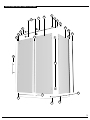
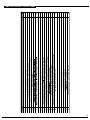
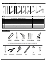
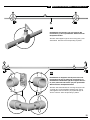
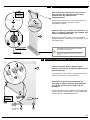
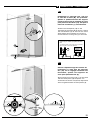
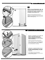
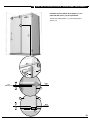
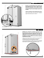
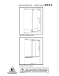
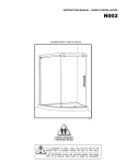
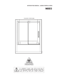
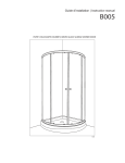
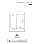
K004
MANUEL DU PROPRIÉTAIRE / OWNER’S MANUAL
PORTE DE DOUCHE | SHOWER ENCLOSURES
2 PERSONNES REQUIS
2 PEOPLE REQUIRED
IL EST OBLIGATOIRE D’AVOIR UNE OSSATURE
MURALE POUR FIXER LA BARRE DE ROULEMENT
IT IS MANDATORY TO HAVE A WALL STUD TO
SECURELY FASTEN THE RUNNING RAIL TO THE WALL
07.08
table
des matiÈres
fixe / fixed
panel
of contents
1 panneau
/ table
liste des piÈces...................................................... 3
table des piÈces.....................................................4
quincaillerie........................................................ 5
outils.................................................................. 5
INSTALLATION DU jambage......................................... 6
panneau de porte................................................... 7
panneau de retour................................................. 7
panneau de retour (suite)....................................... 8
panneau de retour (suite)....................................... 9
barre de roulement.............................................. 10
supports de verre................................................. 11
SUPPORTS infÉrieurs............................................... 11
panneau fixe........................................................12
panneau fixe (suite)............................................... 13
SEUIL DE RETENTION................................................ 13
panneau fixe........................................................ 14
panneau fixe (SUITE)...............................................15
panneau de porte.................................................. 16
panneau de porte (SUITE)........................................ 17
poignÉe droite..................................................... 17
JOINT DE COTÉ DE LA PORTE....................................... 18
BUTOIRS............................................................... 19
SILICONE..............................................................19
PARTS LISTING......................................................... 3
parts table........................................................... 4
PROVIDED HARDWARE................................................ 5
REQUIRED TOOLS AND MATERIALS.................................. 5
wall jamb INSTALLATION........................................... 6
door panel........................................................... 7
return panel......................................................... 7
return panel (continued)........................................ 8
return panel (continued)........................................ 9
running rail........................................................ 10
Glass holders...................................................... 11
glass clips........................................................... 11
fixed panel..........................................................12
fixed panel (continued).......................................... 13
THRESHOLD........................................................... 13
fixed panel........................................................... 14
FIXED panel (CONTINUED).......................................... 15
door panel.......................................................... 16
door panel (CONTINUED)......................................... 17
straight handle................................................... 17
DOOR PANEL SIDE GASKET.......................................... 18
STOPPERS.............................................................. 19
SILICONE..............................................................19
instructions gÉnÉrales / general instructions
-- Lire attentivement et complètement le manuel d’installation
avant de procéder.
-- Des changements peuvent se faire au produit sans préavis.
Utilisez les instructions fournies avec le produit.
●sÉcuritÉ
-- Il est recommandé de porter des lunettes de sécurité en tout
temps lors de l’installation.
-- En tout temps, 2 personnes sont requis pour l’installation.
●Calfeutrage
-- Aucun scellant n’est nécessaire à l’intérieur de la douche.
-- Tous les modèles sont équipés de joints transparents d’étanchéité.
-- Pour les modèles avec des jambages, si vous prévoyez installer
votre porte de douche sur une base en céramique, les tuiles
doivent couvrir complètement le dessous de ceux-ci.
●entretien
-- Ne jamais utiliser de poudre ou de tampon de récurage, ni
d’instrument tranchant sur les parties en métal ou en verre.
Il suffit de nettoyer la porte avec une solution d’eau et de
détergent doux afin de conserver l’aspect neuf des panneaux
de verre et du cadre en aluminium.
-- Nous recommandons de passer une raclette de douche sur les
panneaux de verre après chaque utilisation.
-- Read this manual carefully and completely before
proceeding.
-- Product specifications are subject to change without notice. Use the installation instructions supplied with the product.
●safety
-- It is recommended that you wear safety glasses at all times
during the installation.
-- At all times, 2 people are required for this installation.
●waterproofing
-- No sealant is required inside the shower.
-- All models are equipped with transparent sealing gaskets.
-- For models with wall jambs, if your shower door is to be
installed over ceramic tiles, the tiles should lay completely
under the wall jambs.
●maintenance
-- Never use scouring powder pads or sharp instruments on
metal pieces or glass panels.
-- An occasional wiping down with a mild soap diluted in water
is all that is needed to keep the panels and aluminum parts
looking new.
-- We recommend wiping the glass panels with a squeegee after
each use.
2
liste des pieces / parts listing
18
5
2
5
1
4
14
16b
4
16a
3
15
17
12
16c
11
8
19
6
7
13
9
10
3
Barre de roulement - Running rail
Ensemble de roulettes double - Set of double rollers
Support mural pour barre de roulement- Wall bracket for running rail
Butoir - Door stopper
1
2
3
4
5
6
7
8
9
10
11
12
13
14
15
16a
16b
16c
17
18
19
Seuil de rétention (panneau de retour) - Threshold (return panel)
Joint de coté pour panneau de porte couilissante - Door panel side gasket
- Fixed panel gasket
Joint inférieur de la porte - Door bottom gasket
Support de verre pour panneau de retour - Return panel glass mount bracket
Jambage (Plat) - Wall jamb (Flat)
Extenseur universel - Universal expander
Panneau de retour - Return panel
Joint d'Etanchéité - Gasket
Panneau de porte - Door panel
- Fixed panel
Équerre de coin 90º - 90º Corner Glass Clip
Guide central inférieur - Bottom center guide
Poignée droite - Straight handle
PIÈCES - PARTS
ITEM
1
2 sets
1
2
2
2
1
1
1
1
1
1
1
1
1
1
1
1
1
1
2
QTY
table des piÈces / parts table
4
quincaillerie / hardware
20
21
22
23
25
24
26
27
28
ITEM
QUINCAILLERIE - HARDWARE
QTY
20
Vis auto-perçante - Self-drilling screw #6-1”
Vis - Screw #12-3”
Encre- Anchor (Blanc - White)
Vis auto-perçante - Self drilling screw
Cheville - Wall plug (Orange)
Vis auto-perçante - Self drilling screw #8 - 3/8
Capouchon couvre-vis - screw cap
Clé L hexagonale- Hex L key 3 mm
Clé L hexagonale - Hex L key 6mm (7/32”)
2
2
21
22
23
24
25
26
27
28
3
3
4
3
4
1
1
outils / tools
*
SCIE À MAIN
HACKSAW
TOURNEVIS
SCREWDRIVERS
PERÇEUSE
DRILL
MÈCHE 1/4˝ & 1/8˝
1/4˝& 1/8˝ DRILL BITS
SCELLANT
SILICONE
*Si vous installez les panneaux sur des tuiles en céramique, utilisez une mèche 1/4˝ à céramique.
If the shower panels are to be assembled on ceramic tiles, use a 1/4˝ drill bit for ceramic tiles.
CRAYON
PENCIL
PINCE COUPANTE
CUTTING PLIER
RUBAN À MESURER
TAPE MEASURE
NIVEAU
LEVEL
MAILLET
MALLET
BLOC
BLOCK
5
1
installation du jambage / wall jamb installation
1A
Marquer le centre du seuil de la base (B) à
l’aide d’un ruban à mesurer.
1A
Using a measuring tape, mark the center of the
threshold of the base.
1B
Rapporter au mur la ligne de centre du seuil
de la base établit à l’étape précédente.
Assurer la verticalité en utilisant une
équerre.
B
1B
Using the marking established in the previous step,
run a second line up the wall. Use a level to ensure
verticality of this line.
1C
Placer le jambage (15) au mur en s’assurant
que les trous sont centralisés à la ligne du mur
et que les trous de cote du jambage soient
de la cote intérieure de la douche. Poursuivre
a percé, en utilisant les trous de la jambière
comme référence, à travers le mur en utilisant
une mèche de 1/8˝.
1C
15
INTÉRIEUR DE
LA DOUCHE
INTERIOR
SHOWER SIDE
1D
23
15
15
24
Place the wall jamb onto the wall while ensuring
that the wall jamb holes align themselves onto the
line running up the wall. Moreover, the side holes
of the wall jamb (15) should face the interior of the
shower. Proceed to drilling, using a 1/8˝drill bit,
through the wall using the wall jamb holes as a
reference.
1D
Introduire une goutte de silicone dans chaque
trou percé au mur avant d’y insérer une cheville orange (24). Repositionner le jambage et
fixer le à l’aide de vis auto perçante #8-1 1/4
(23).
Put a drop of silicone into each hole drilled on the
wall prior to insert an orange wall plug (24).
Reposition and fasten the wall jamb with #8-1 1/4
Self drilling screws (23).
6
2 panneau de porte / door panel
17
2A
2A
2A
17
INTÉRIEUR DE
LA DOUCHE
INTERIOR
SHOWER SIDE
13
2B
En utilisant la boîte d’emballage en carton
comme plateforme, insérer le joint inférieur
de la porte (13) au panneau de porte (17).
Cela se fait à l’aide d’un bloc protecteur et un
maillet. Prener note de l’orientation du joint.
Using the cardboard packaging box as platform,
install bottom door gasket (13) onto door panel
(17) using a block and a mallet. Notice the gasket
orientation.
17
12
2B
INTÉRIEUR DE
LA DOUCHE
INTERIOR
SHOWER SIDE
3A
Installer le joint du panneau fixe (12) à la porte
coulissante (17) telle qu’illustrée. Assurer que
le rebord du verre soit propre afin d’assurer
une adhérence accrue du joint.
Install door side gasket (12) onto sliding door
panel (17). Ensure that edge of glass is clean so
as to ensure proper adhesion of the gasket.
16b
3
14
3A
INTÉRIEUR DE
LA DOUCHE
INTERIOR
SHOWER SIDE
3B
panneau de retour / return panel
Installer le support de verre pour panneau
de retour (14) au panneau de retour (16b) tel
qu’illustre.
15
6
Install the return panel glass mount bracket (14) to
the return panel (16b) as shown.
3B
Insérer les joints aux supports inférieurs
pour panneau fixe (6) tel qu’illustre.
3C
Insert gaskets into the glass clips for bottom
fixed panel (6).
6
3C
2 1/4˝
(60mm)
16b
2 1/4˝
(60mm)
Positionner les supports inférieurs pour panneau fixe (6) sur le panneau de retour (16b).
Prener note des distances indiquées.
Position the glass clips for bottom of fixed
panel to the return panel (16b). Note the distances
illustrated.
7
3
continuÉ / continued
3D
3D
Glisser l’extenseur (16a.c) à l’intérieur du
jambage (15) afin d’assurer que le panneau
de retour (16b), ainsi que les supports
inférieurs pour panneau fixe (6), reposent
sur le seuil de la base.
15
16a.c
Slide the return panel assembly (16a.b.c) into the
wall jamb (15) so as to allow the return panel (16b),
along with the clips for bottom of fixed panel (6), to
rest on the threshold of the base.
16b
15
3E
16a.c
3E
6
6
Mark the glass clips for bottom of fixed panel (6)
locations on the base, ensuring that the leading
edge of the return panel is tangent to the center
of threshold of the base. Draw a line marking the
position of return panel threshold (10) in relation to
the return panel based on dimension B. Proceed
to removing the return panel assembly (16a.b.c) as
well as the glass clips (6).
3F
S
10
10
3G
Marquer l’emplacement des supports
inférieurs (6) sur la base en s’assurant que
l’avant du panneau de retour est aligné au
centre du seuil de la base. Tirer ensuite une
ligne marquant l’emplacement avant du seuil
de rétention pour panneau de retour (10) par
rapport au panneau de retour en se fiant à la
dimension B. Proceder ensuite à retirer l’assemblage du panneau de retour (16a.b.c) et
les supports inférieurs (6).
20
6
10
3F
Assurer d’appliquer une ligne de silicone sur
le dessous du seuil de rétention pour panneau
de retour (10) avant de procéder à l’étape
suivante.
Apply a bead of silicone to the underside of the return panel threshold before proceeding to the next
step.
3G
CENTRE DU
SEUIL DE LA
BASE*
CENTER OF
THRESHOLD*
16b
B
Securiser les supports inférieurs (6) sur la
base contre le seuil de rétention (10) aux
emplacements indiques à l’étape 3E.
Securiser avec de vis auto perçante #6-1
(20) avant de replacer les joints. Reposer de
nouveau l’assemblage du panneau de retour
(16a.b.c) tel qu’établit à l’étape 3D.
Secure glass clips for bottom of fixed panel on the
base, against the threshold (10) at the markings
established in step 3E. Secure these with #6-1
self-drilling screws (21) before repositioning the
gaskets. Reposition the return panel assembly
(16a.b.c) as established in step 3D.
8
3 continuÉ / continued
3H
3H
16b
Assurer l’équarrissage du panneau de
retour (16b). Si un nivelage a besoin d’être
fait, ajuster la verticalité de l’extenseur (16a)
par rapport au jambage (15).
Ensure that the return panel (16b) is vertical by way
of a level. If there need be a correction, adjust the
verticality of the expander (16a) in relation to the
wall jamb (15).
3I
3I
Une fois que l’équarrissage du panneau de
retour (16b) est fait, serrer l’extenseur (16a)
au jambage (15), à l’aide d’une pince afin de
garder le panneau de retour a niveau.
16a.c
Once the return panel (16b) has been adjusted,
secure the expander (16a) to the wall jamb (15)
by way of a clamp so as to keep the return panel
level.
15
16b
3J
15
3J
A l’aide des vis auto perçante #8- 3/8 (25), ainsi
que les capuchons couvre-vis (26), sécuriser
en permanence le jambage a l’extenseur.
25
By way of #8- 3/8 screws (25), as well as screw
caps (26), permanently secure the wall jamb (15)
to the expander (16a).
26
15
16c
16b
9
4
barre de roulement / running rail
4
1
4A
ositionner les butoirs (4) sur la barre de
P
roulement (1) tels qu’illustrés. Sécurisez-les
temporairement.
Position the stoppers (4) on the running rail (1) as
illustrated. Secure them temporarily in place.
4
E
4B
E
ositionner le support mural pour barre de
P
roulement (3) sur la barre de roulement (1).
Positionner l’extenseur (E) du support de verre pour panneau de retour (14) tel qu’illustré.
Sécurisez-les temporairement.
Position the wall bracket for running rail (3) on the
running rail (1) as illustrated. Position the return
panel glass mount bracket (14) expander (E) as
shown. Secure them temporarily in place.
10
1
5
/ fixed panel
INTÉRIEUR DE
LA DOUCHE
INTERIOR
SHOWER SIDE
Fixer la barre de roulement (1) au panneau
fixe (18) avec les supports de verre pour
panneau fixe (5). Sécurisez-les
temporairement.
Fasten the running rail (1) to the fixed panel (18)
with the glass holders (5). Secure them
temporarily in place.
5
5
SUPPORTS de verre / glass HOLDERS
ssurez-vous que la barre de roulement (1)
A
soit à la hauteur maximale par rapport aux
trous du panneau fixe (18).
1
18
nsure that the running rail (1) is at the highest
E
possible position in reference to the holes of the
fixed panel (18). TROU DE VERRE
GLASS HOLE
Poser le panneau de verre sur une surface plane
et matelassee tel qu’une serviette ou un carton
afin d’eviter des dommages
RONDELLE
WASHER
Place the glass panel onto a cushioned surface, such
as a towel or cardboard so as to prevent unwanted
damage.
5
supports infÉrieurs / bottom glass clips
7
6
18
7
6
Insérer les joints dans le guide central
inférieur (7) ainsi que le support inférieur pour
panneau fixe (6).
Insert gaskets in the bottom center guide (7) and
glass clip for bottom of fixed panel (6).
Positionner le guide central inférieur (7)
ainsi que le support inférieur pour panneau
fixe (6) sur le panneau fixe large (18) tel
qu’illustre.
6
Position the glass clip for bottom of fixed panel (6)
and the bottom center guide (7) on the wide fixed
panel (18) at the illustrated positions.
7
INTÉRIEUR DE
LA DOUCHE
INTERIOR
SHOWER SIDE
1 1/2”
(38 mm)
ALIGNER AU
REBORD DU
VERRE
/
FLUSH WITH
GLASS
7
6
11
6
panneau fixe / fixed panel
6A
Positionner le panneau fixe (18) sur
le seuil de la base (B), tel qu’illustré.
Ajuster le positionnement du support
mural (3) ainsi que du support de verre
pour panneau de retour (14) afin que la
barre de roulement (1) soit sécurise.
20
Position the fixed panel (18) on the
threshold of the base (B) as shown. Adjust
the wall bracket (3) as well as the return
panel glass mount bracket (14) so as to
ensure that the running rail (1) is secured.
Le guide du bas (7) peut dépasser le seuil de
douche (B), en autant qu’il puisse être bien
fixé.
The bottom guide (7) can hang off the threshold
(B) as long as it can be well-fastened.
18
7
18
INTÉRIEUR DE
LA DOUCHE
INTERIOR
SHOWER SIDE
B
B
6B
Assurer l’équarrissage de la barre de
roulement (1) ainsi que du panneau
fixe (18). Si un réglage horizontal est
nécessaire, ajuster les supports de
verre pour panneau fixe (5).
Ensure that the running rail (1) is level and
that the fixed panel (18) is square. If a
horizontal correction is required, adjust and
level the glass holders for fixed panel (5).
18
1
90°
90°
5
12
6 continuÉ / continued
6C
3
Marquer les emplacements des vis
pour le support mural pour barre de
roulement (3). De plus, marquer l’emplacement du support inférieur (6) et
du guide central inférieur (7).
3
5
Mark the screw locations for the wall
bracket for running rail (3) on the wall as
well as the placement the glass clip (6) and
bottom center guide (7). 6C
6
7
7
6
7
seuil de rÉtention / threshold
S
9A
Enlever le panneau fixe (18) afin de
placer le seuil de rétention (9).
Assurer d’appliquer une ligne de
silicone (S) sous le seuil de rétention
avant l’installation.
9
20
7
Remove the fixed panel (18) so as to
allow placement of the threshold (9)
onto the base. Ensure that a bead of
silicone (S) is applied to the underside of
the threshold before installing.
6
18
Sécuriser le support inférieur (6) et
le guide central inférieur (7) avec
des vis auto perçante (20) et insérer
les joints.
Secure glass clip (6) and bottom
center guide (7) with self drilling screws
(20) and insert gaskets.
13
8
3
10A
panneau fixe / fixed panel
8A
Enlever la barre de roulement (1) du
support mural pour barre de roulement
(3) et du support de verre pour panneau
de retour (14). Percez des trous dans le
mur avec une mèche à céramique, en se
rendant jusqu’à l’ossature.
OSSATURE
WALL STUD
Remove running rail (1) from wall bracket for
running rail (3) and return panel glass mount
bracket (14). Drill holes in wall with a drill bit,
intended for ceramic tiles, through to the wall
stud.
3
21
Fixer le support mural (3) avec des vis
#12-3 (21).
Fasten the wall brackets (3) with #12-3 (21).
3
8B
18
8B
Réinstaller le panneau fixe (18) en
s’assurant qu’il est installé à l’intérieur
du support inférieur pour panneau fixe
(6) ainsi que le guide central
inférieur (7).
E
Insert large fixed panel (20) back, ensuring
that it’s placed in the bottom glass clip (6)
and bottom center guide (7).
3
Glisser l’extenseur (E) pour le support
mural (3) ainsi que celui du support
de verre pour panneau de retour (14)
afin de faire connexion avec le support
même. Sécuriser à l’aide des vis.
E
14
Slide expanders (E) to bridge the gap over
wall bracket for running rail (3) as well as
glass mount bracket for return panel (14) .
Fasten set screws.
14
8
continuÉ / continued
8C
Appliquer une ligne de silicone au coin du
panneau de retour (16c) et du petit panneau
fixe (18) avant de procéder a Securiser le tout
avec des équerres de coin 90° (19).
Apply a bead of silicone at the corner of the narrow fixed panel (18) and the return
panel (16c). Proceed to securing the
assembly with 90° glass corner clips (19).
8C
16b
18
19
15
9 panneau de porte / door panel
2
Assembler un ensemble de roulettes
double (2) aux trous supérieurs du
panneau de porte (17) telle qu’illustrée.
Assemble a set of double rollers (2) to the door
panel’s (17) top holes, as illustrated.
17
9A
INTÉRIEUR DE
LA DOUCHE
INTERIOR
SHOWER SIDE
17
9B
17
Installer le panneau de porte (17) en
posant un ensemble de roulettes (2) sur
la barre de roulement (1).
9B
Install door panel (17), ensuring that a set of
rollers (2) are positioned over the running rail
(1).
13
7
Assurer que le panneau de porte (17)
est installé à l’intérieur du guide central
inférieur (7).
Ensure that the door panel (17) is placed
within the bottom center guide (7).
16
9 suite / continued
RONDELLE
WASHER
9C
Installer le deuxième ensemble de
roulettes double (2) aux trous inférieurs du
panneau de porte (17). Ajustez-les, à l’aide
des rondelles excentriques, pour qu’il y ait
contact avec la barre de roulement (1).
Install second set of double rollers (2) to the
bottom holes of door panel (17), making sure
that they are tangent to the running rail (1) by
way of the excentric washers.
1
2
TROU DU VERRE
RONDELLE
WASHER
GLASS HOLE
10 poignÉe droite / straight handle
Installer la poignée droite (8) sur le
panneau de porte (17). Assurer que les
rondelles protectrices s’interposent entre
le verre et les poignées de chaque côté.
Install straight handle (8) onto door panel (17).
Ensure that clear washers on either side of
glass are installed.
8
17
11 joint DE COTÉ de la porte / door panel side gasket
/ fixed panel
Installer
13 le joint latéral de la porte (11) au
panneau de porte (17) tel qu’illustré.
Install door side gasket (11) onto sliding door
panel (17).
17
11
HAUT
TOP
1/2”
(12.57 mm)
11
11
17
BAS
BOTTOM
7
18
12 butoirs / stoppers
4
Ajuster le positionnement des butoirs (4)
afin d’obtenir une ouverture ainsi qu’une
fermeture optimale de la porte coulissante. Assurer que le joint du panneau fixe
s’écrase contre le mur lorsque la porte est
fermée.
Adjust the position of the stoppers (4) so as to
ensure a maximum opening and closing range.
Fixed panel gasket (12) should be collapsed
against wall when door is closed.
4
PORTE FERMEE / DOOR CLOSED
13 SILICONE
Appliquer du scellant en silicone (S) entre le bas
du panneau fixe (18) et le panneau de retour (16b)
et leurs seuils de rétention appropries (9) (10). Une
application de silicone le long de ces seuils de
rétention est aussi suggérée ainsi que le long du
jambage (15). Dans tous les cas, cela se fait de
l’extérieur de la base.
Apply silicone (S) between the bottom of the fixed panel
(18) and return panel (16b) and the ir appropriate
thresholds (9) (10). Silicone application is also
recommended along the length of both these thresholds
and along the length of the wall jamb (15). In all cases,
this is done from the outside of the shower area.
HEURES
HOURS
S
19