1
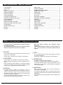
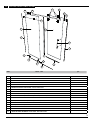
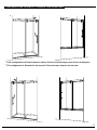
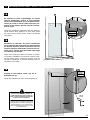
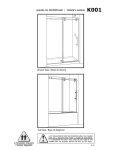
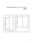
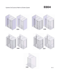
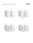
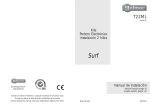
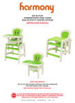
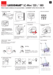
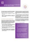
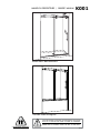
MANUEL DU PROPRIÉTAIRE | OWNER’S MANUAL
K001
Shower base / Base de douche
Tub base / Base de baignoire
2 PERSONNES REQUISES
2 PEOPLE REQUIRED
IL EST OBLIGATOIRE D’AVOIR UNE OSSATURE MURALE SUR CHAQUE
CÔTÉ DE LA DOUCHE POUR FIXER LA BARRE DE ROULEMENT.
IT IS MANDATORY TO HAVE A WALL STUD ON EACH SIDE OF THE
SHOWER UNIT TO SECURELY FASTEN THE RAIL TO THE WALLS.
10.13
table
des matiÈres
1
/ / table of contents
liste des piÈces...................................................... 3
quincaillerie........................................................ 4
outils.................................................................. 4
INSTALLATION DU JOINT.............................................. 5
BARRE DE ROULEMENT............................................... 6
SUPPORTS DE VERRE.................................................. 7
SUPPORTS INFÉRIEURS................................................ 7
PLACEMENT DU PANNEAU FIXE...................................... 8
PLACEMENT DU PANNEAU FIXE (SUITE)............................ 9
SEUIL DE RÉTENTION................................................. 9
SUPPORTS MURAUX.................................................. 10
PANNEAU DE PORTE COULISSANTE................................. 11
PANNEAU DE PORTE COULISSANTE (SUITE)....................... 12
POIGNÉE DROITE..................................................... 12
installation des joints..........................................13
BUTOIRS............................................................... 14
SILICONE............................................................... 14
PARTS LISTING......................................................... 3
PROVIDED HARDWARE................................................ 4
REQUIRED TOOLS AND MATERIALS.................................. 4
GASKET INSTALLATION............................................... 5
RUNNING RAIL......................................................... 6
GLASS HOLDERS....................................................... 7
GLASS CLIPS............................................................ 7
FIXED PANEL PLACEMENT............................................ 8
FIXED PANEL PLACEMENT (CONTINUED)........................... 9
THRESHOLD............................................................ 9
WALL BRACKETS...................................................... 10
SLIDING DOOR........................................................ 11
SLIDING DOOR (CONTINUED)....................................... 12
STRAIGHT HANDLE................................................... 12
gaskets installation.............................................13
STOPPERS.............................................................. 14
SILICONE............................................................... 14
instructions gÉnÉrales / general instructions
-- Lire attentivement et complètement le manuel d’installation avant de procéder.
-- Des changements peuvent se faire au produit sans préavis.
Utilisez les instructions fournies avec le produit.
●sÉcuritÉ
-- Il est recommandé de porter des lunettes de sécurité en tout
temps lors de l’installation.
-- En tout temps, 2 personnes sont requis pour l’installation.
●Calfeutrage
-- Aucun scellant n’est nécessaire à l’intérieur de la douche.
-- Tous les modèles sont équipés de joints transparents d’étanchéité.
-- Pour les modèles avec des jambages, si vous prévoyez installer
votre porte de douche sur une base en céramique, les tuiles
doivent couvrir complètement le dessous de ceux-ci.
●entretien
-- Ne jamais utiliser de poudre ou de tampon à récurer, ni
d’instrument tranchant sur les parties en métal ou en verre.
Il suffit de nettoyer la porte avec une solution d’eau et de
détergent doux afin de conserver l’aspect neuf des panneaux
de verre et du cadre en aluminium.
-- Nous recommandons de passer une raclette de douche sur les
panneaux de verre après chaque utilisation.
-- Read this manual carefully and completely before
proceeding.
-- Product specifications are subject to change without notice. Use the installation instructions supplied with the
product.
●safety
-- It is recommended that you wear safety glasses at all times
during the installation.
-- At all times, 2 people are required for this installation.
●waterproofing
-- No sealant is required inside the shower.
-- All models are equipped with transparent sealing gaskets.
-- For models with wall jambs, if your shower door is to be
installed over ceramic tiles, the tiles should lay completely
under the wall jambs.
●maintenance
-- Never use scouring powder pads or sharp instruments on
metal pieces or glass panels.
-- An occasional wiping down with a mild soap diluted in water
is all that is needed to keep the panels and aluminum parts
looking new.
-- We recommend wiping the glass panels with a squeegee after
each use.
2
1
LISTE DES PIÈCES / PARTS LISTING
5
3B
2B
1
3A
2A
4
7
6
10
8
9
12
16
11
14
13
17
15
ITEM
PIÈCES - PARTS
QTY
BARRE DE ROULEMENT- RUNNING RAIL
1
2A,2B
SUPPORTS MURAUX- WALL BRACKET
2
3A,3B
BUTOIRS- STOPPERS
2
4
SUPPORTS DE VERRE- GLASS HOLDERS
2
5
ROULETTESTWIN ROLLERS
2 SET/PAIRS
6
PANNEAU DE PORTE COULISSANTE- SLIDING DOOR PANEL
1
7
PANNEAU FIXE- FIXED PANEL
1
8
POIGNÉE DROITE- STRAIGHT HANDLE
1
9
1
JOINT DE RÉTENTION (PORTE)- GASKET (DOOR)
1
10
JOINT DE RÉTENTION (PANNEAU FIXE)- GASKET (FIXED PANEL)
1
11
SUPPORT INFÉRIEUR POUR PANNEAU FIXE- BOTTOM GLASS CLIP
1
12
JOINT (FIXATION DE VERRE)- GASKET (GLASS CLIP)
2
13
GUIDE INFÉRIEUR- BOTTOM GUIDE
1
14
JOINT (GUIDE DU BAS)- GASKET (BOTTOM GUIDE)
1
15
SEUIL DE RÉTENTION- THRESHOLD
1
16
JOINT DE PORTE DE COTÉ- DOOR PANEL SIDE GASKET
1
17
JOINT DE PORTE INFÉRIEUR- DOOR PANEL BOTTOM GASKET
1
3
quincaillerie / hardware
19
18
21
20
ITEM
QUINCAILLERIE - HARDWARE
QTY
18
#12-3 VIS AUTO-PERCANTE / #12-3 SELF-THREADING SCREW
4
19
#6-1 VIS AUTO PERCANTE / #6-1 SELF-THREADING SCREW
2
20
HEX KEY 3mm
1
21
HEX KEY 6mm (7/32˝)
1
outils / tools
*
SCIE À MAIN
HACKSAW
TOURNEVIS
SCREWDRIVERS
PERCEUSE
DRILL
MÈCHE 1/4˝ & 1/8˝
1/4˝& 1/8˝ DRILL BITS
SCELLANT
SILICONE
*Si vous installez les panneaux sur des tuiles en céramique, utilisez une mèche 1/4˝ à céramique.
If the shower panels are to be assembled on ceramic tiles, use a 1/4˝ drill bit for ceramic tiles.
CRAYON
PENCIL
PINCE COUPANTE
CUTTING PLIER
RUBAN À MESURER
TAPE MEASURE
NIVEAU
LEVEL
MAILLET
MALLET
BLOC
BLOCK
4
configurations possibles / possible configurations
*
* Cette configuration est illustrée dans ce manuel. Suivre les mêmes étapes pour la base de baignoire.
* This configuration is illustrated in this manual. Follow the same steps for the tub base.
5
1
installation du joint / gasket installation
1A
6
En utilisant la boite d’emballage en carton
comme plateforme, insérer le joint inférieur
de la porte coulissante (17) à la porte coulissante (6). Cela se fait à l’aide d’un bloc protecteur et un maillet. Prenez note de l’orientation du joint.
Using the cardboard packaging box as platform,
install bottom door gasket (17) onto door panel
(6) using a block and a mallet. Notice the gasket
orientation.
1A
6
INTÉRIEUR DE
LA DOUCHE
INTERIOR
SHOWER SIDE
17
1B
Introduire le panneau de porte coulissante
(6) à l’intérieur de la douche afin de simplifier
les étapes à suivre. Poser le panneau sur une
surface plane et matelassée comme une serviette ou un carton. Cela évite tout dommage
au panneau ou la base.
Place door panel (6) inside the shower to simplify following installation procedures. Ensure placing the panel onto a cushioned surface, such as
a towel or cardboard, to prevent damage either to
the panel or the base.
1B
Installer le joint latéral court (10) sur le
panneau fixe (7).
10
INTÉRIEUR DE
LA DOUCHE
INTERIOR
SHOWER SIDE
Install short gasket (10) onto the fixed panel (7).
THE INSTALLATION SHOWN IS BASED ON
PLUMB FINISHED WALLS AND A LEVELLED
BASE. IF THESE CONDITIONS ARE NOT MET,
PLEASE ADJUST ACCORDINGLY.
L’INSTALLATION ILLUSTRÉE EST BASÉE SUR
DES MURS FINIS D’APLOMB ET UNE BASE DE
DOUCHE NIVELÉE. SI CES CONDITIONS NE
SONT PAS PRÉSENTÉES, VEUILLEZ AJUSTER
EN CONSÉQUENCE.
Court
SHORT
7
6
2
barre de roulement / running rail
1
2A
3B
3A
ositionner les butoirs (3A & B) sur la barre
P
de roulement (1) tels qu’illustrés. Sécurisezles temporairement.
Position the stoppers (3A & B) on the running rail (1)
as illustrated. Secure them temporarily in place.
1
2B
ositionner les supports muraux (2A & B) sur
P
la barre de roulement (1) tels qu’illustrés. Sécurisez-les temporairement.
2A
Position the wall brackets (2A & B) on the running
rail (1) as illustrated. Secure them temporarily in
place.
2B
7
3
SUPPORTS de verre / glass HOLDERS
7
Fixez la barre de roulement (1) au panneau
fixe (7) avec les supports de verre (4).
Sécurisez-les temporairement.
1
asten the running rail (1) to the fixed panel (7)
F
with the glass holders (4).
Secure them temporarily in place.
4
ssurez-vous que la barre de roulement (1)
A
soit à la hauteur maximale par rapport aux
trous du panneau fixe (7).
nsure that the running rail (1) is at the highest posE
sible position in reference to the holes of the fixed
panel (7).
1
4
TROU DE VERRE
GLASS HOLE
4
RONDELLE
WASHER
supports infÉrieurs / glass clips
Insérer les gaines protectrices (12) dans les
supports inférieurs (11) et (13).
13
Insert bottom gaskets (12) in the bottom glass
clips (11) and (13).
11
Positionnez le support inférieur (11) et le
guide inférieur (13) sur le panneau fixe tel
qu’illustré.
Position the bottom glass clip and bottom guide
on fixed panel as illustrated.
1 1/2”
(38 mm)
ALIGNER AU
REBORD DU
VERRE
1/8˝
FLUSH WITH
GLASS
13
INTÉRIEUR DE
LA DOUCHE
INTERIOR
SHOWER SIDE
11
11
13
8
5 positionnement du panneau fixe / fixed panel placemement
Le guide du bas (13) peut dépasser le seuil
de douche (B), en autant qu’il puisse être
bien fixé.
The bottom guide (13) can hang off the threshold
(B) as long as it can be well-fastened.
5A
Positionner le panneau fixe (7) sur le seuil
de la base (B), tel qu’illustré.
13
INTÉRIEUR DE
LA DOUCHE
INTERIOR
SHOWER SIDE
6
Position the fixed panel assembly (7) on threshold of base (B) as shown .
B
Régler le panneau fixe (7) afin que le joint
de rétention (10) s’écrase contre le mur.
Cela se fait à travers la barre de roulement
(1).
1/2” max (12.7mm)
1
Adjust the fixed panel (7), by way of the running
rail (1), so as to force the gasket (10) against the
wall.
7
10
7
B
5B
Assurer que la barre de roulement (1) ainsi
que le panneau fixe (7) sont à niveau. Si un
réglage horizontal est nécessaire, ajuster
les attaches de verre (4).
4
Ensure that the running rail (1) is level and that
the fixed panel (7) is square. If a horizontal correction is required, adjust and level the glass
fasteners (4).
1
90°
7
90°
90°
9
5
SUITE / CONTINUED
2B
5C
arquer les emplacements les supports
M
muraux (2A & 2B) des deux côtés de la
douche. De plus, marquer l’emplacement
des attaches de verre (11) (13).
Mark the locations for the wall brackets (2A &
B) on the walls on both sides of shower as well
as the placement of the bottom glass clips
(11) (13).
2A
11
13
11
6
13
S
seuil de rÉtention / threshold
6A
15
Enlever le panneau fixe afin de placer le
seuil de rétention (15). Assurer d’appliquer
une ligne de silicone (S) sous le seuil de
rétention avant l’installation.
6A
Remove the fixed panel assembly so as to allow
placement of the threshold (15) onto the base.
Ensure that a bead of silicone (S) is applied to
the underside of the threshold before installing.
15
6B
6B
Sécuriser les fixations de verre (11) (13)
avec des vis autopercante (19).
Secure glass clips (11) (13) with self-drilling
screws (19).
11
19
19
13
10
7 supports muraux / wall brackets
7A
Enlever la barre de roulement (1) du support mural (2). Percez des trous dans les
murs avec une mèche à céramique, en se
rendant jusqu’à l’ossature.
Mark the screw locations on the walls on both
sides of shower. Remove the running rail (1)
from the wall brackets (2). Drill holes in walls
until wall stud is reached with a drill bit intended
for ceramic tiles.
OSSATURE
WALL STUD
Fixer le support mural (2) avec des vis
#12-3 (18).
Fasten the wall brackets (2) with screw #12-3
(18).
2
18
2
11
7
7B
Réinstaller le panneau fixe (7) en s’assurant qu’il est installé à l’intérieur des fixations de verre (11) (13).
13
Insert fixed panel (7) back, ensuring that it’s
placed in the bottom glass clips (11) (13).
2
E1
Glisser l’extenseur (E1 & E2) au support
mural (2) correspondant et sécuriser à
l’aide des vis.
Slide expander (E1 & E2) over matching wall
bracket (2) and fasten set screws.
2
E2
11
8 panneau de porte coulissante / sliding door
eccentric WASHER
INSTALLED AS SHOWN
RONDELLE excentrique
INSTALLÉE TEL QU’ILLUSTRÉE
8A
Assembler les 2 roulettes du haut (5) au
panneau de la porte coulissante (6) telles
qu’illustrées.
5
Assemble the 2 top rollers (5) to the door panel
(6) as illustrated.
6
INTÉRIEUR DE
LA DOUCHE
INTERIOR
SHOWER SIDE
1
6 5
8B
6
Installer le panneau de porte coulissante
(6) en posant les roulettes (5) sur la barre
de roulement (1).
Install sliding door (6) ensuring that rollers (5)
are fixed over the running rail (1).
ssurer que le panneau de porte coulissante
A
(6) est installé à l’intérieur du guide (13).
13
Ensure that sliding door (6) is placed within the
bottom guide (13).
Assurer que le panneau de porte coulissante
(6) est d’aplomb contre le mur. Ajuster la
rondelle excentrique de la roulette (5) si
nécessaire.
Ensure that the sliding door (6) is flush against
the wall. Adjust the roller’s (5) eccentric washer
if necessary.
12
8 suite / continued
RONDELLE
WASHER
5
8C
Installer les roulettes du bas (5). Ajustez
-les pour qu’il y ait contact avec la barre de
roulement (1).
Install the bottom rollers, making sure that they
are tangent to the running rail (1).
1
5
À l’aide des rondelles excentriques,
ajuster les roulettes afin d’atteindre un
parallélisme avec la barre de roulement.
Through the use of the nonconcentric washers,
adjust rollers so that the sliding door panel is
parallel to the running rail.
RONDELLE
WASHER
TROU DU VERRE
GLASS HOLE
9 poignÉe / handle
Voir la fiche d’installation et installer la
poignée tel qu’illustré.
See sheet for installation and install the handle
as shown.
8
*Poignée A illustré /
Handle A shown
13
10 installation des joint / gasket installation
long
long
10A
Installer le joint latéral long (9) sur la
porte coulissante (6) tel qu’illustré.
Install long gasket (9) onto sliding door
panel as shown (6).
10A
6
9
10B
INTÉRIEUR DE
LA DOUCHE
INTERIOR
SHOWER SIDE
Installer le joint de côté (16) à la porte
coulissante (6) tel qu’illustré.
Install door side gasket (16) onto sliding door
panel (6).
6
10B
16
HAUT
TOP
16
6
16
BAS
BOTTOM
17
14
11 butoirs / stoppers
10
Ajuster le positionnement des butoirs (3A &
B) afin d’obtenir une ouverture ainsi qu’une
fermeture optimale de la porte coulissante.
Assurer que le joint de rétention (9) de la
porte coulissante s’écrase contre le mur.
PORTE FERMEE / DOOR CLOSED
3B
3A
3A
9
Adjust the position of the stoppers (3A & B) so
as to ensure a maximum opening and closing
range. Ensure that the sliding door gasket (9) is
forced against the wall.
PORTE OUVERTE / DOOR OPEN
6
12 SILICONE
7
APPROX.
3” (76.2 mm)
Appliquer du scellant en silicone entre le
bas du panneau fixe et le seuil de la base.
Une application de silicone le long du seuil
de retention est aussi suggère. Dans les
deux cas, cela se fait de l’extérieur de la
base.
Apply silicone between the bottom of the fixed
panel and the threshold of the base. Silicone
application along the length of the threshold is
also suggested. In both cases, it is done from
the outside of the shower area.
HEURES
HOURS
15