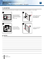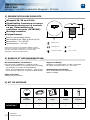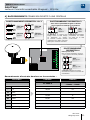
1
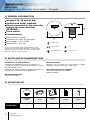
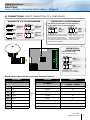
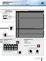
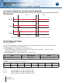
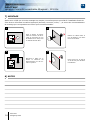
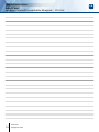
EN ENGLISH
FR FRANCAIS
DGLPTWLC
Indoor/Outdoor Proximity Card Readers - Wiegand
Lecteurs Proximité intérieur/extérieur - Wiegand
Range: Integrated access control / Gamme: Contrôle d’Accès intégré
INSTALLATION MANUAL
MANUEL D’INSTALLATION
Group Products
INSTALLATION MANUAL
DGLPTWLC
Indoor/OutdoorProximityCardreaders-Wiegand
1] GENERAL INFORMATION
Wiegand 26, 30 and 44 bits.
Audible and visual feedback
Direct connection to the controller
through the door controller
(INTBUSW).
Flush mount.
Polycarbonate.
Sealed(resinmoulded).
Connectionby4pair6/10thcable
Inputvoltage:12VAC/DC.
Consumption:100mA.
WEEE & RoHS
Conforms to European directive R&TTE 99/5/CE and
according to the harmonised standards : ETS 301 489
and ETS 300-330-1-Ed 2001. Conforms to CEM applied
directives : EN 50133, EN 50130-4.
CE Certification
IP64
R&TTE Certification
-25°C to +55°C
2] NOTES AND RECOMMENDATIONS
Installation recommendations
Tomaketheinstallationsecure,rememberto:
-installthevaristoronthelockingsystem,inparallelonthesupplycircuit.
-placea120ohmsresistance,betweenAandB,on
thelastdoorcontrolleroftheRS485BUS.
Recommended cable
4pair6/10thcable.
Wiring reminder
Warning: do not route your wires close to cables
carryingahighcurrent(e.g.:230VAC).
Recommended power supplies
Twopowersuppliesaresuitable:
ARD12orBS60.
3] MOUNTING KIT
DGLPTWLC
2
cdvi.com
cdvigroup.com
DGLPTWLC
reader
Screw
electronic
box
jumper
Varistor
1
1
1
2
1
INSTALLATION MANUAL
DGLPTWLC
Indoor/OutdoorProximityCardreaders-Wiegand
4] CONNECTIONS: DIRECTCONNECTIONTOACONTROLLER
DIPSWITCH 1 & 2 POSITIONNING
OFF/OFF
26bits
OFF/ON
44bits
ON/OFF
30bits
ON/ON
Non
allocated
1 2 3 4
DIPSWITCH 3 POSITIONNING
The buzzer and the LED’s can be controlled
by the reader or by an external device.
OFF
CDVI
Mode
ON
Centaur
Mode
In standard, when a card or a tag is
placed within the reader the orange
LED is activated and the buzzer
emit a tone. The Centaur controller
can manage the LED and the buzzer
to program other operations.
The controller or the
audio entry system can
manage the LED and the
buzzer to program
other operations.
DIPSWITCH 4
POSITIONNING
Pulls up 12 V or 5V
Opencollectoroutputs:
OFF
Pullup5V
ON
Pullup12V
Selecttheoutputvoltage
accordingtotheinstallation.
Direct connections to the controller terminal blocks:
DGLPTWLC
CENTAUR
LINKNET
CT-V900-A
LT20PB - LT20PBIP
LT20AC - LT20IP
+
Inputvoltage12VDC
+12V
12VDC
-
0V
R2/0V
0V
H
Clock
D0
Data0
R2/D0
CL
D1
Data1
R2/D1
DA
B
Buzzer
V
GreenLED
R
RedLED
cdvi.com
cdvigroup.com
3
INSTALLATION MANUAL
EN
DGLPTWLC
Indoor/OutdoorProximityCardreaders-Wiegand
5] CONNECTIONS: CONNECTIONTOTHEDOORCONTROLLER(INTBUSW)
DIPSWITCH 1 & 2
POSITIONNING
OFF/ON
44bits
DIPSWITCH 3
POSITIONNING
The buzzer and the LED’s
can be controlled by the reader
or by an external device.
OFF
CDVI
Mode
The controller or the audio entry system
can manage the LED and the buzzer to program
other operations.
DGLPTWLC
INTBUSW
DGLPTWLC
8 points terminal blocks:
+
Alimentation12VDC
-
0V
H
Clock
D0
Data0
D1
Data1
B
Buzzer
V
GreenLED
R
RedLED
Strike
Electromagnet
Varistor
Power supply
Two different configurations,
are possible:
12VDConly
(Asstandard)
Cutthestrap
12VACor24VDC
Shielded
cable
Door contact (not used)
Connect E and M
4
cdvi.com
cdvigroup.com
To other door
controllers (INTBUSW)
INSTALLATION MANUAL
EN
DGLPTWLC
Indoor/OutdoorProximityCardreaders-Wiegand
INTBUSW (Door controller)
DIPSWITCH 4
POSITIONNING
Terminal block : Motherboard
Pulls up 5V
Opencollectoroutputs:
OFF
Pullup5V
V
Inputvoltage-
12
Inputvoltage+
1
DataO
2
Clock
3
Data1
Terminal block : Motherboard
Selecttheoutputvoltage.
R
N/Ccontacteletromagneticlock(+)
C
Commoncontactpowersupply(+)
T
N/Ocontactelectricrelease
R
N/Ccontactalarm
C
Common
T
N/Ocontactalarm
+ ~ - InputvoltageDCorAC,12Vor24V
P1
Request-to-enterinput
M
Common(P1etP2)
P2
Request-to-enterinput
E
Doorcontact,N/C(Doorclosed)andN/O(Dooropen)
L
Readeractivationimput(N/O)readerenabledand(N/C)readerdisabled
M
Common(EandM)or(EandL)
A
RS485Bus(AlltheAmustbeconnectedtogetherindaisychain)
B
RS485Bus(AlltheBmustbeconnectedtogetherindaisychain)
Terminal block - 3 points : Piggybackboard
Without jumper : without clock
With jumper : with clock
7
LED>Redcolor
8
LED>Greencolor
9
Buzzer
STAND ALONE MODE
CENTRALIZED MODE
TELACCESS
-TERENA,
-UGM-UGL,
-UGP/40
-PDN345BUSPROX
-Dipswitchaddresssetup
-Dip4=ON
DIP SWITCH adressing
1
2
3
4
Mode
ON
ON
ON
ON
Frontplate
OFF
ON
ON
ON
Reader1
ON
OFF
ON
ON
Reader2
OFF
OFF
ON
ON
Reader3
ON
ON
OFF
ON
Reader4
-Addressprogrammingduringinstallation
-Dip4=OFF
ST1 (Programming jumper)
ST1 (Programming jumper) : Normal
Normal (As standard)
Installation
cdvi.com
cdvigroup.com
5
INSTALLATION MANUAL
EN
DGLPTWLC
Indoor/OutdoorProximityCardreaders-Wiegand
6] OUTPUT FORMATS 26, 30 AND 44 BITS WIEGAND
Chronograms
1logic
0logic
\DATA1
\CLOCK
\DATA0
50µs
2ms
50µs
2ms
Open collector output with internal pulls up 1K at +5V or +12V according the ST4 position.
26-bit Wiegand Output
ST5 jumper on 1.
Format26-bithexadecimal.Theoutputformatis26-bitWiegand(Signals:DATA1,DATA0andCLOCK)
Theframeismadeof26-bitandbuiltasfollow:
1 - First parity: 1-bit–evenparityforthefirst12-bit
Codeofthebadge:6halfbyterepresentthelast6digitofthecode(4bit=1digitofacode)
Eachbyteistransferredfrombit7tobit0.
2 - Second parity: 1bit–paritéimpairedes12derniersbits
Bit 1
Bit 2 à bit 25
Bit 26
EvenParityonbit2tobit13
Data(24bit)
OddParityonbit14…bit25
Example: code of the badge is 0100166A37.
1
0001
0110
0110
1010
0011
0111
0
Parity1
1
6
6
A
3
7
Parity2
The code transmitted is in hexadecimal format 166A37
Parity 1:
Parity 2:
6
0
1
0
1
if
if
if
if
the
the
the
the
cdvi.com
cdvigroup.com
number
number
number
number
of
of
of
of
1
1
1
1
in
in
in
in
bit
bit
bit
bit
2 to bit 13 is even,
2 to bit 13 is odd.
14 to bit 25 is odd,
14 to bit 25 is even.
INSTALLATION MANUAL
EN
DGLPTWLC
Indoor/OutdoorProximityCardreaders-Wiegand
Format Wiegand 30 bits
ST5 jumper on 2.
Signalsoutputinopencollectorswithpullupin30-bithexadecimalformat.Theoutputformatfromthe
proximityreaderis30-bitwiegand(Signal:DATA1,DATA0andCLOCK)andisstructuredasfollow:
1 - First parity :
1bit–evenparityforthefirst14-bit
Code:Acodeisformedfrom7halfbyte.
Eachbyteistransferredfrombit7tobit0.
2 - Second parity: 1bit–oddparityforthelast14-bit
Bit 1
Bit 2 à bit 29
Bit 30
EvenParityfrombit2tobit15
Data(28-bit)
OddParityfrombit16tobit29
Example A: Temic card decimal code: 689905 (in hexadecimal: A86F1).
1
0000
0000
1010
0110
0110
1111
0001
0
Parity1
0
0
A
8
6
F
1
Parity2
The code number of the card is 00A86F1 in hexadecimal
Example B: EM badge hexadecimal code: 0100166A37
1
0000
0000
0001
0001
0110
1011
0110
1
Parité1
0
0
6
6
A
3
7
Parité2
The code transmitted is in hexadecimal format 0166A37
Parity 1: 0
1
Parity 2: 0
1
if
if
if
if
the
the
the
the
number
number
number
number
of
of
of
of
1
1
1
1
in
in
in
in
bit
bit
bit
bit
2 to bit 15 is even,
2 to bit 15 is odd.
16 to bit 29 is odd,
16 to bit 29 is even.
44- bit Wiegand Format Output
ST5 jumper on 3.
44-bithexadecimalformat.Theoutputformatfromtheproximityreaderis44-bit(Signal:DATA1,DATA0
andCLOCK)andisstructuredasfollow:
1 - Data:
10digitcodenumberhexadecimalMSBytefirst.
Eachhexadecimaldigit=4bit,MSBitfirst
2 - LRC :
4bit=orrestrictedinbetweenthedigitofthedata,MSBitfirst.
Bit 1 to bit 40
Bit 41 to bit 44
DataMSBitfirst
LRC
Example A: EM badge hexadecimal code: 01001950C3.
0000
0000
0000
0000
0001
1001
0101
0000
1100
0011
0011
0
1
0
0
1
9
5
0
C
3
3
The code number of the card is: 01001950C3 in hexadecimal code.
cdvi.com
cdvigroup.com
7
INSTALLATION MANUAL
EN
DGLPTWLC
Indoor/OutdoorProximityCardreaders-Wiegand
7] MOUNTING
Aftercheckingthatthefittingkitiscomplete,youcanstartthefinalinstallationofyourreader.
1
2
FixtheDGLPTWLCbox
insidethefrontpanel
(neartheheadmounting
screwhole)withdouble
sided
adhesivetape.
3
4
Connectthecable
totheboxandmake
theconnectionstothe
controllerorthepanel.
8] NOTES
8
Feedthecablesthrough
themountingscrew
hole,andtheninto
themountingnut.
cdvi.com
cdvigroup.com
Fixthenuttothehead
studtocompletethe
installation.
INSTALLATION MANUAL
EN
DGLPTWLC
Indoor/OutdoorProximityCardreaders-Wiegand
cdvi.com
cdvigroup.com
9
MANUEL D’INSTALLATION
FR
DGLPTWLC
LecteursProximitéencastrableWiegand-125Khz
1] PRESENTATION DES PRODUITS
Wiegand 26, 30 ou 44 bits.
Signalisation lumineuse et sonore
Connexion directe sur la centrale
ou par l’intermédiaire du
contrôleur de porte (INTBUSW).
Montage encastré.
Polycarbonate.
Etanche(surmoulagerésine).
Raccordementparcâble4paires6/10e.
Alimentation:12VAC/DC.
Consommation:100mA.
Conforme à la directive européenne R&TTE 99/5/CE
et selon les normes harmonisées : ETS 301 489 et ETS
300-330-1-Ed 2001. Conforme aux normes CEM
appliquées : EN 50133, EN 50130-4.
DEEE & RoHS
Certification CE
IP64
Certification R&TTE
-25°C à +55°C
2] RAPPELS ET RECOMMANDATIONS
Recommandations d’installation
Poursécuriserl’installation,n’oubliezpasde:
-placerlavaristancesurlesystèmedeverrouillage,
enparallèle,auniveaudel’alimentation.
-placerunerésistancede120ohms,entreAetB,
surlederniercontrôleurdeporteduBUSRS485.
Câble préconisés
Câble4paires6/10ème.
Rappel de câblage
Attentiondenepaspasservosfilsàproximité
decâbles«Courantfort»(ex:230VAC).
Alimentations préconisées
Deuxalimentationssontadaptées:
ARD12ouBS60.
3] KIT DE MONTAGE
DGLPTWLC
10
cdvi.com
cdvigroup.com
Tête
DGLPTWLC
Ecrou
Boitier
Cavalier
Varistance
1
1
1
2
1
MANUEL D’INSTALLATION
FR
DGLPTWLC
LecteursProximitéencastrableWiegand-125Khz
4] RACCORDEMENTS CONNEXIONDIRECTEÀUNECENTRALE
POSITIONNEMENT DIPSWITCH 1 & 2
OFF/OFF
26bits
OFF/ON
44bits
ON/OFF
30bits
ON/ON
Nonattribué
POSITIONNEMENT DIPSWITCH 3
Vous avez la possibilité de gérer le buzzer
et les voyants en interne ou en externe.
OFF
Mode
CDVI
ON
Mode
Centaur
1 2 3 4
En standard, la lecture d’un
badge active la LED orange
et
déclenche
le
buzzer.
La centrale Centaur permet
néanmoins de définir d’autres
états pour la LED et le buzzer.
La centrale ou la platine
permettent de définir
les états de la LED
et du buzzer.
POSITIONNEMENT
DIPSWITCH 4
Pulls up 12 V ou 5V
Pourlessortiesàcollecteurouvert,il
yadeuxniveauxdesortiespossibles:
OFF
Pullup5V
ON
Pullup12V
Permet à l’utilisateur de choisir
la tension de sortie en fonction de
l’installation.
Raccordements directs des borniers sur les centrales :
DGLPTWLC
CENTAUR
LINKNET
CT-V900-A
LT20PB - LT20PBIP
LT20AC - LT20IP
+
Alimentation12VDC
+12V
12VDC
-
0V
R2/0V
0V
H
Clock
D0
Data0
R2/D0
CL
D1
Data1
R2/D1
DA
B
Buzzer
V
Voyantvert
R
Voyantrouge
cdvi.com
cdvigroup.com
11
MANUEL D’INSTALLATION
FR
DGLPTWLC
LecteursProximitéencastrableWiegand-125Khz
5] RACCORDEMENTS CONNEXIONAVECCONTRÔLEURDEPORTE(INTBUSW)
POSITIONNEMENT
DIPSWITCH 1 & 2
OFF/ON
44bits
POSITIONNEMENT
DIPSWITCH 3
Vous avez la possibilité de gérer
le buzzer et les voyants en interne
ou en externe.
OFF
Mode
CDVI
La centrale ou la platine permettent
de définir les états de la LED et du buzzer.
DGLPTWLC
INTBUSW
DGLPTWLC
Bornier 8 points :
+
Alimentation12VDC
-
0V
H
Clock
D0
Data0
D1
Data1
B
Buzzer
V
Voyantvert
R
Voyantrouge
Gâche
Ventouse
Varistance
Alimentation
Pour l’alimentation,
il y a deux modes possibles :
12
12VDCuniquement
(Configurationusine) Coupezlestrap
12VACou24VDC
cdvi.com
cdvigroup.com
Câble
blindage
Si vous ne souhaitez
pas de gestion de l’etat
porte : Relier E et M
Vers d’autres contrôleur
de portes (INTBUSW)
MANUEL D’INSTALLATION
FR
DGLPTWLC
LecteursProximitéencastrableWiegand-125Khz
INTBUSW (Contrôleur de porte)
POSITIONNEMENT
DIPSWITCH 4
Bornier 5 points : Cartemère
Pulls up 12 V ou 5V
Pourlessortiesàcollecteurouvert,il
yadeuxniveauxdesortiespossibles:
OFF
Pullup5V
V
Alimentation-
12
Alimentation+
1
DataO
2
Clock
3
Data1
Bornier 16 points : Cartemère
Permet à l’utilisateur de choisir
la tension de sortie.
R
ContactN.FporteVentouse(+)
C
Contactcommun+Alimentation
T
ContactN.OporteGâche
R
ContactN.Falarme
C
Contactcommun
T
ContactN.Oalarme
+ ~ - AlimentationDCouAC12Vou24VDC
P1
Boutonpoussoirintérieur
M
Massecommune(P1etP2)
P2
Boutonpoussoirextérieur
E
Contactfermetureporte,N.F.(Portefermée)etN.O.(Porteouverte)
L
Contactautorisationlecturedubadge(N.O)autoriséeet(N.F)interdite
M
Massecommune(EetM)ou(EetL)
A
BusRS485(touslesAdoiventêtrereliésentreeuxsouslaformed’unechaîne)
B
BusRS485(touslesBdoiventêtrereliésentreeuxsouslaformed’unechaîne)
Bornier 3 points : Cartefille
Sans cavalier : sans clock
Avec cavalier : avec clock
7
Signalisation>couleurrouge
8
Signalisation>couleurverte
9
Buzzer
MODE AUTONOME
MODE CENTRALISÉ
TELACCESS
-TERENA,
-UGM-UGL,
-UGP/40
-PDN345BUSPROX
-Programmationdel’adressepardipswitch
-Dip4=ON
Adressage DIPSWITCH
1
2
3
4
Mode
ON
ON
ON
ON
Façade
OFF
ON
ON
ON
Lecteur1
ON
OFF
ON
ON
Lecteur2
OFF
OFF
ON
ON
Lecteur3
ON
ON
OFF
ON
Lecteur4
-Programmationdel’adresseparinstallation
-Dip4=OFF
ST1 (Cavalier de programmation)
ST1 (Cavalier de programmation) : Normal
Normal (Config. usine)
Installation
cdvi.com
cdvigroup.com
13
MANUEL D’INSTALLATION
FR
DGLPTWLC
LecteursProximitéencastrableWiegand-125Khz
6] FORMAT DE SORTIE WIEGAND 26, 30 ET 44 BITS
Chronogrammes
1logique
0logique
\DATA1
\CLOCK
\DATA0
50µs
2ms
50µs
2ms
Sorties en collecteur ouvert avec pulls up internes de 1K au +5V ou +12V selon la position de ST4
Format Wiegand 26 bits
Cavalier ST5 sur 1.
Format26bitshexadécimal.Lacommunications’effectueparuneliaisondetypeWiegand26bits
(Signaux:DATA1,DATA0etCLOCK).Latrameestconstituéed’unetotalitéde26bits
etsedécomposecommesuit:
1
1ère parité : 1bit–paritépairedes12premiersbits
Codedubadge:3motsd’unoctetreprésentantles6dernierstermes.
Chaquemotesttransmisbitdepoidsfortenpremier.
2 - 2ème parité: 1bit–paritéimpairedes12derniersbits
Bit 1
Bit 2 à bit 25
Bit 26
Paritépairesurbit2àbit23
Donnée(24bits)
Paritéimpairesurbit14àbit25
Exemple : pour un badge dont le code hexadécimal est 0100166A37.
1
0001
0110
0110
1010
0011
0111
0
Parité1
1
6
6
A
3
7
Parité2
Le code émis est 166A37 en hexadécimal
Parité 1 :
Parité 2 :
14
0
1
0
1
si
si
si
si
le
le
le
le
nombre
nombre
nombre
nombre
cdvi.com
cdvigroup.com
de
de
de
de
1
1
1
1
dans
dans
dans
dans
bit
bit
bit
bit
2 à bit 13 est paire,
2 à bit 13 est impaire.
14 à bit 25 est impaire,
14 à bit 25 est paire.
MANUEL D’INSTALLATION
FR
DGLPTWLC
LecteursProximitéencastrableWiegand-125Khz
Format Wiegand 30 bits
Cavalier ST5 sur 2.
Format30bitshexadécimal.Lacommunications’effectueparuneliaisondetypeWiegand30bits(Signaux:
DATA1,DATA0etCLOCK).Latrameestconstituéed’unetotalitéde30bitsetsedécomposecommesuit:
1 - 1ère parité : 1bit–paritépairedes14premiersbits
Codedubadge:7quartetsreprésentantlecodedubadge
Chaquemotesttransmisbitdepoidsfortenpremier.
2 - 2ème parité: 1bit–paritéimpairedes12derniersbits
Bit 1
Bit 2 à bit 29
Bit 30
Paritépairesurbit2àbit15
Donnée(28bits)
Paritéimpairesurbit16àbit29
Exemple A : pour une carte ayant le code décimal : 689905 (en hexadécimal : A86F1).
1
0000
0000
1010
0110
0110
1111
0001
0
Parité1
0
0
A
8
6
F
1
Parité2
Le code émis est 00A86F1 en hexadécimal
Exemple B : pour un badge ayant le code hexa : 0100166A37
1
0000
0000
0001
0001
0110
1011
0110
1
Parité1
0
0
6
6
A
3
7
Parité2
Le code émis est 0166A37 en hexadécimal
Parité 1 :
Parité 2 :
0
1
0
1
si
si
si
si
le
le
le
le
nombre
nombre
nombre
nombre
de
de
de
de
1
1
1
1
dans
dans
dans
dans
bit
bit
bit
bit
2 à bit 15 est paire
2 à bit 15 est impaire
16 à bit 29 est impaire
16 à bit 29 est paire
Format Wiegand 44 bits
Cavalier ST5 sur 3.
Format44bitshexadécimal.Lacommunications’effectueparuneliaisondetypeWiegand44bits(Signaux:
DATA1,DATA0etCLOCK).Latrameestconstituéed’unetotalitéde44bitsetsedécomposecommesuit:
Données :
10chiffreshexadécimaux(octetdepoidsfortenpremier),
Chaquechiffrehexadécimal=4bits(bitdepoidsfortenpremier).
LRC :
4bit=OUexclusifentreleschiffresdeladonnée(bitdepoidsfortenpremier).
Bit 1 à bit 40
Bit 41 à bit 44
Codedubadge
LRC
Exemple A : pour un badge ayant le code hexa : 01001950C3.
0000
0000
0000
0000
0001
1001
0101
0000
1100
0011
0011
0
1
0
0
1
9
5
0
C
3
3
Le code émis est : 01001950C3 en hexadécimal.
cdvi.com
cdvigroup.com
15
MANUEL D’INSTALLATION
DGLPTWLC
LecteursProximitéencastrableWiegand-125Khz
FR
7] MONTAGE
Aprèsavoirvérifiéquelekitdemontageestcomplet,vousallezpouvoirprocéderàl’installationfinalede
votrelecteur.Réunissezlematérielapproprié(Perceuse,tournevis,mètre,...)etsuivezlesrecommandations
demontagequicorrespondentaulecteurquevousallezinstaller.
1
2
Fixez le boîtier du DGLPTWLCàl’intérieurdelafaçade (à proximité du trou
defixationdelatête)avec
unadhésifdouble-face.
3
4
Branchez le câble sur le
boîtier et effectuez les
branchements vers la centraleouplatine.
8] NOTES
16
Passez les câbles dans le
trou de fixation, puis dans
l’écroudefixation.
cdvi.com
cdvigroup.com
Fixez l’écrou sur le pas de
visdelatêtepourfinaliser
l’installation.
MANUEL D’INSTALLATION
FR
DGLPTWLC
LecteursProximitéencastrableWiegand-125Khz
cdvi.com
cdvigroup.com
17
MANUEL D’INSTALLATION
DGLPTWLC
LecteursProximitéencastrableWiegand-125Khz
18
cdvi.com
cdvigroup.com
FR
MANUEL D’INSTALLATION
FR
DGLPTWLC
LecteursProximitéencastrableWiegand-125Khz
cdvi.com
cdvigroup.com
19
Reference : G0301FR0318V03
Extranet : EXE-CDVI_IM DGLPTWLC CMYK A5 EN-FR 03
CDVI Group
FRANCE (Headquarters/Siège social)
Phone: +33 (0)1 48 91 01 02
Fax: +33 (0)1 48 91 21 21
CDVI
TAIWAN
Phone: +886 (0)42471 2188
Fax: +886 (0)42471 2131
CDVI
ITALIA
Phone: +39 0331 97 38 08
Fax: +39 0331 97 39 70
CDVI
FRANCE
Phone: +33 (0)1 48 91 01 02
Fax: +33 (0)1 48 91 21 21
CDVI
SWITZERLAND
Phone: +41 (0)21 882 18 41
Fax: +41 (0)21 882 18 42
CDVI
MAROC
Phone: +212 (0)5 22 48 09 40
Fax: +212 (0)5 22 48 34 69
CDVI AMERICAS
CDVI
CHINA
Phone: +86 (0)10 87664065
Fax: +86 (0)10 87664165
[CANADA - USA]
Phone: +1 (450) 682 7945
Fax: +1 (450) 682 9590
CDVI SWEDEN
[SWEDEN - DANEMARK - NORWAY - FINLAND]
Phone: +46 (0)31 760 19 30
Fax: +46 (0)31 748 09 30
CDVI BENELUX
CDVI IBÉRICA
CDVI UK
[BELGIUM - NETHERLAND - LUXEMBOURG]
[SPAIN - PORTUGAL]
[UNITED KINGDOM - IRELAND]
Phone: +32 (0) 56 62 02 50
Fax: +32 (0) 56 62 02 55
Phone: +34 (0)935 390 966
Fax: +34 (0)935 390 970
Phone: +44 (0)1628 531300
Fax: +44 (0)1628 531003
cdvigroup.com
DIGIT
FRANCE
Phone: +33 (0)1 41 71 06 85
Fax: +33 (0)1 41 71 06 86
Toutes les informations mentionnées à titre indicatif sur le présent document (photos, dessins, caractéristiques
techniques et dimensions) peuvent varier et sont susceptibles de modifications sans notification préalable.
All the information contained within this document (photos, drawing, features, specifications and dimensions)
could be perceptibly different and can be changed without prior notice.
Manufacturing Access Control since 1985