1
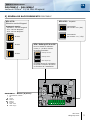
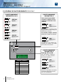
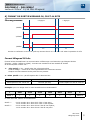
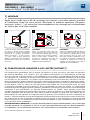
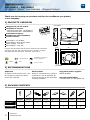
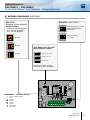
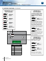
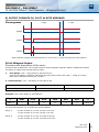
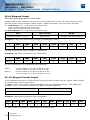
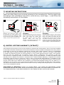
* Voir conditions de garantie à vie limitée. / Refer to Limited Lifetime Warranty.
FR
FRANCAIS
EN
ENGLISH
DGLPMWLC
DGLIMWLC
DGLIMWLC
DGLPMWLC
Indoor/Outdoor 13.56 MHZ Mifare® Card Readers - Wiegand
Lecteurs Mifare® 13,56 MHz intérieur/extérieur - Wiegand
Range: Integrated Access Control / Gamme: Contrôle d’Accès centralisé
INSTALLATION MANUAL
MANUEL D’INSTALLATION
Group Products
MANUEL D’INSTALLATION
FR
DGLPMWLC - DGLIMWLC
Lecteurs Mifare® 13,56 MHz Wiegand
Merci pour l’achat de ce produit et pour la confiance que vous accordez
à notre entreprise.
1] PRESENTATION DES PRODUITS
Wiegand 26, 30 ou 44 bits.
Disponible en version :
- Inox saillie (Réf : DGLIMWLC),
- Polycarbonate saillie (Réf : DGLPMWLC).
Electronique résinée.
Signalisation lumineuse et sonore.
Montage en saillie.
Inox.
DGLPMWLC
CE
ISTAN
E
E RÉS
HAUT ANDALISM
AU V
Technologie : 13,56 Mhz.
Raccordement par câble 4 paires 6/10e.
Alimentation : 12 V DC.
Consommation : 100 mA.
98
19,50
DEEE
Certification CE
Certification FCC CFR 47
part 15 compliance
IP53
-25°C à +70°C
77
Conforme à la directive européenne R&TTE 99/5/CE
et selon les normes harmonisées : ETS 301 489 et ETS
300-330-1-Ed 2001. Conforme aux normes CEM appliquées : EN
50133, EN 50130-4.
DGLIMWLC
2] RAPPELS ET RECOMMANDATIONS
Recommandations d’installation
Pour sécuriser l’installation, n’oubliez
pas de placer la varistance sur le
système de verrouillage en parallèle
au niveau de l’alimentation.
Environnement
Si vous installez ces lecteurs dans
un environnement marin/salin,il
est préconisé de passer du vernis
en bombe sur les contacts après
câblage afin de prévenir le risque
d’oxydation.
Alimentations préconisées
ARD12 et BS60.
Câble préconisés
Câble 4 paires 6/10ème (AWG 24).
3] ÉLÉMENTS FOURNIS
Varistance
Outil
Diax®
Vis Diax®
5x35mm
Cheville
métal
Cache Vis
gauche
Cache Vis
droite
Cheville
plastqiue
Vis à bois
3x40mm
DGLIMWLC
1
1
2
2
-
-
-
-
DGLPMWLC
1
-
-
-
2
2
2
2
2
cdvi.com
cdvigroup.com
MANUEL D’INSTALLATION
FR
DGLPMWLC - DGLIMWLC
Lecteurs Mifare® 13,56 MHz Wiegand
5] SCHÉMA DE RACCORDEMENTS DGLPMWLC
ST5-ST6 : Voyants
ST1-ST2 :
Sélection sortie Wiegand
Format de sortie :
- Standard : 26 bits Wiegand
- ST1: 30 bits Wiegand
- ST2: 44 bits Wiegand
Commande
par niveau «O» (OV)
Commande
par niveau «1» (+5V)
26 bits
30 bits
ST4 : Pulls up 12 V ou 5V
Pour les sorties à collecteur
ouvert, il y a deux niveaux
de sorties possibles :
44 bits
Pulls up à 12 V
Pulls up à 5 V
Pas de pull up
Ce strap permet à l’utilisateur
de choisir la tension de sortie
en fonction de l’installation.
DGLPMWLC* - Bornier (8 points) :
+
H
D0
D1
B
V
R
alimentation 12VDC
0V
Clock
Data 0
Data 1
Buzzer
LED verte
LED rouge
cdvi.com
cdvigroup.com
3
MANUEL D’INSTALLATION
FR
DGLPMWLC - DGLIMWLC
Lecteurs Mifare® 13,56 MHz Wiegand
5] SCHÉMA DE RACCORDEMENTS DGLIMWLC
POSITIONNEMENT
DIPSWITCH 1 & 2
POSITIONNEMENT
DIPSWITCH 3
Vous avez la possibilité
de gérer le buzzer et les
voyants en interne ou en
externe.
OFF/OFF
26 bits
1 2 3 4
ON/OFF
30 bits
ON
ON
Mode Centaur
En standard, la lecture d’un
badge active la LED orange et
déclenche le buzzer.
La centrale Centaur permet
néanmoins de définir d’autres
états pour la LED et le buzzer.
OFF/ON
44 bits
ON/ON
Non attribué
OFF
Mode CDVI
La centrale ou la platine permettent de définir les états
de la LED et du buzzer.
POSITIONNEMENT
DIPSWITCH 4
Pulls up 12 V ou 5V
Pour les sorties à collecteur
ouvert, il y a deux niveaux
de sorties possibles :
Bornier (8 points)
4
cdvi.com
cdvigroup.com
+
alimentation 12VDC
-
0V
H
Clock
D0
Data 0
D1
Data 1
B
Buzzer
V
LED verte
R
LED rouge
OFF
Pull up 5V
ON
Pull up 12V
Permet à l’utilisateur de choisir
la tension de sortie en fonction de l’installation.
MANUEL D’INSTALLATION
FR
DGLPMWLC - DGLIMWLC
Lecteurs Mifare® 13,56 MHz Wiegand
6] FORMAT DE SORTIE WIEGAND 26, 30 ET 44 BITS
Chronogrammes
1 logique
0 logique
\DATA1
\CLOCK
\DATA0
50 μs
2ms
50 μs
2ms
Sorties en collecteur ouvert avec pulls up internes de 1K au +5V ou +12V selon la position de ST4
Format Wiegand 26 bits
Format 26 bits hexadécimal. La communication s’effectue par une liaison de type Wiegand 26 bits
(Signaux : DATA1, DATA0 et CLOCK). La trame est constituée d’une totalité de 26 bits
et se décompose comme suit :
1-
1ère parité : 1 bit – parité paire des 12 premiers bits
Code du badge : 3 mots d’un octet représentant les 6 derniers termes.
Chaque mot est transmis bit de poids fort en premier.
2 - 2ème parité: 1 bit – parité impaire des 12 derniers bits
Bit 1
Bit 2 à bit 25
Bit 26
Parité paire sur bit 2 à bit 23
Donnée (24 bits)
Parité impaire sur bit 14 à bit 25
Exemple : pour un badge dont le code hexadécimal est 0100166A37.
1
0001
0110
0110
1010
0011
0111
0
Parité 1
1
6
6
A
3
7
Parité 2
Le code émis est 166A37 en hexadécimal
Parité 1 :
Parité 2 :
0
1
0
1
si
si
si
si
le
le
le
le
nombre
nombre
nombre
nombre
de
de
de
de
1
1
1
1
dans
dans
dans
dans
bit
bit
bit
bit
2 à bit 13 est paire,
2 à bit 13 est impaire.
14 à bit 25 est impaire,
14 à bit 25 est paire.
cdvi.com
cdvigroup.com
5
MANUEL D’INSTALLATION
FR
DGLPMWLC - DGLIMWLC
Lecteurs Mifare® 13,56 MHz Wiegand
Format Wiegand 30 bits
Format 30 bits hexadécimal. La communication s’effectue par une liaison de type Wiegand 30 bits (Signaux :
DATA1, DATA0 et CLOCK). La trame est constituée d’une totalité de 30 bits et se décompose comme suit :
1 - 1ère parité : 1 bit – parité paire des 14 premiers bits
Code du badge : 7 quartets représentant le code du badge
Chaque mot est transmis bit de poids fort en premier.
2 - 2ème parité: 1 bit – parité impaire des 12 derniers bits
Bit 1
Bit 2 à bit 29
Bit 30
Parité paire sur bit 2 à bit 15
Donnée (28 bits)
Parité impaire sur bit 16 à bit 29
Exemple A : pour une carte ayant le code décimal : 689905 (en hexadécimal : A86F1).
1
0000
0000
1010
0110
0110
1111
0001
0
Parité 1
0
0
A
8
6
F
1
Parité 2
Le code émis est 00A86F1 en hexadécimal
Exemple B : pour un badge ayant le code hexa : 0100166A37
1
0000
0000
0001
0001
0110
1011
0110
1
Parité 1
0
0
6
6
A
3
7
Parité 2
Le code émis est 0166A37 en hexadécimal
Parité 1 :
Parité 2 :
0
1
0
1
si
si
si
si
le
le
le
le
nombre
nombre
nombre
nombre
de
de
de
de
1
1
1
1
dans
dans
dans
dans
bit
bit
bit
bit
2 à bit 15 est paire
2 à bit 15 est impaire
16 à bit 29 est impaire
16 à bit 29 est paire
Format Wiegand 44 bits
Format 44 bits hexadécimal. La communication s’effectue par une liaison de type Wiegand 44 bits (Signaux :
DATA1, DATA0 et CLOCK). La trame est constituée d’une totalité de 44 bits et se décompose comme suit :
Données :
10 chiffres hexadécimaux (octet de poids fort en premier),
Chaque chiffre hexadécimal = 4 bits (bit de poids fort en premier).
LRC :
4 bit = OU exclusif entre les chiffres de la donnée (bit de poids fort en premier).
Bit 1 à bit 40
Bit 41 à bit 44
Code du badge
LRC
Exemple A : pour un badge ayant le code hexa : 01001950C3.
0000
0000
0000
0000
0001
1001
0101
0000
1100
0011
0011
0
1
0
0
1
9
5
0
C
3
3
Le code émis est : 01001950C3 en hexadécimal.
6
cdvi.com
cdvigroup.com
MANUEL D’INSTALLATION
FR
DGLPMWLC - DGLIMWLC
Lecteurs Mifare® 13,56 MHz Wiegand
7] MONTAGE
Après avoir vérifié que le kit de montage est complet, vous allez pouvoir procéder
à l’installation finale de votre lecteur. Réunissez le matériel approprié (Perçeuse,
tournevis, mètre,...) et suivez les recommandations de montage qui correspondent
au lecteur que vous allez installer.
1
A l’aide du lecteur, prenez les marques
pour fixer le produit. Percez le support
de montage au niveau des marques
(Diamètres de perçage préconisés :
plaque de fixation = 4 mm et lecteur
= 6 mm). Grâce à votre schéma de
câblage, prévoyez la sortie des câbles,
cachés dans la surface ou à l’extérieur
(moulure).
2
DGLIMWLC
Placez les chevilles métal dans les
trous, connectez les fils aux borniers
(voir schéma de câblage page 4), puis
fixez le lecteur avec les deux vis DIAX®
grâce à l’outil DIAX®. N’oubliez pas
de placer la varistance au niveau du
système de verrouillage (Voir page 7
«Rappels et préconisations»).
3
DGLPMWLC
Placez les chevilles plastiques dans les
trous, connectez les fils aux borniers
(voir schéma de câblage page 4), puis
fixez les lecteurs avec les deux vis à
bois. Pour finaliser l’installation du lecteur, placez les cache-vis. N’oubliez pas
de placer la varistance au niveau du
système de verrouillage (Voir page 7
«Rappels et préconisations»).
8] CONDITIONS DE GARANTIE À VIE LIMITÉE [EXTRAIT]*
Les sociétés CDVI garantissent que ce produit est dépourvu de tout vice caché, tant dans les matériaux
que dans sa fabrication, à la condition, qu’il soit installé conformément aux préconisations du fabricant
et qu’il n’y ait pas eu d’interventions ou de modifications sur le produit. La responsabilité de CDVI se limite
à la réparation ou à l’échange du produit. CDVI n’assume aucune responsabilité concernant les dommages
sur les biens ou les personnes. Un produit reconnu défectueux par CDVI doit être retourné au serviceaprès-vente de CDVI, après l’obtention du numéro d’autorisation de Retour de Produit(s) Défectueux (RMA).
La responsabilité de CDVI se limite à la réparation ou au remplacement d’un produit ou pièces défectueuses,
en ses ateliers. L’une ou l’autre de ces interventions sont définis par le service-après-vente de CDVI.
Le préjudice imputable à CDVI ne saurait en aucun cas dépasser la valeur du produit. La responsabilité
de CDVI ne peut être engagée auprès de l’acheteur, installateur, client final ou qui que ce soit, lors de dommages
consécutifs à des imperfections ou mauvais fonctionnement du produit. Cette garantie prend effet
à la date d’enregistrement du produit auprès de CDVI, à partir de l’instant ou la date d’enregistrement est
dûment complétée, dans la limite d’un mois, après la date de livraison au client final. Pour obtenir les détails complets de cette garantie et enregistrer votre/vos produit(s) pour bénéficier de cette « Garantie à Vie
limitée ». Veuillez compléter la carte d’enregistrement présente dans la boite du produit et nous la retourner,
par email ou par courrier, à l’adresse de l’entité CDVI la plus proche ou vous enregistrer en ligne à l’adresse
www.cdvigroup.com. Les contacts des entités CDVI sont accessibles en ligne à l’adresse www.cdvigroup.com
ou au dos de la notice d’installation.
EXCLUSIONS DE LA GARANTIE : A l’EXCEPTION DES POINTS EVOQUES PRECEDEMMENT, CDVI N’APPLIQUE
AUCUNE GARANTIE, NI DELIBEREE NI TACITE, A TOUS LES PROBLEMES INCLUANT LE CONDITIONNEMENT,
LE TRANSPORT, LEUR COMMERCIALISATION OU LES CONDITIONS D’UTILISATIONS PARTICULIÈRES.
*Voir conditions de garantie à vie limitée
cdvi.com
cdvigroup.com
7
INSTALLATION MANUAL
EN
DGLPMWLC - DGLIMWLC
13.56 MHZ Mifare® Card Readers - Wiegand Output
Thank you for buying our products and for the confidence you placed
in our company.
1] PRODUCTS OVERVIEW
DGLPMWLC
Wiegand 26, 30 ou 44 bits.
Available in version:
- Stainless steel (Réf : DGLIMWLC),
- Polycarbonate (Réf : DGLPMWLC).
PCB sealed in epoxy.
Audible and visual feedback.
Surface mount.
E
TANC
RESIS
HIGH ANDALISM
TO V
Technologie : 13,56 Mhz.
Connecting by 6/40 4-pair cable.
Input voltage : 12V DC.
Consumption : 100 mA.
77
Certification FCC CFR 47
part 15 compliance
CE Certification
WEEE
98
19,50
Complies with European R&TTE directive 99/5/EC and harmonised
standards: ETS 301 489 and ETS 300-330-1-Ed 2001. Complies
with applicable EMC standards: EN 50133, EN 50130-4.
IP53
-25°C to +70°C
DGLIMWLC
2] RECOMMANDATIONS
Important
To protect the device from back - emf
do not forget to mount the varistor
on the lock in parallel.
Environment
When in a humid area or close to
a sea shore, we recommend applying a varnish on the terminals
to avoid oxidation.
Suggested power supplies
ARD12 & BS60
Recommended cables
4 twisted pairs 0.6 MM (AWG 24).
3] PACKAGE CONTENTS
®
®
Varistor
Diax
spanner
Diax screw
stainless steel
Brass
anchor
DGLIMWLC
1
1
2
2
-
DGLPMWLC
1
-
-
-
2
8
cdvi.com
cdvigroup.com
Plastic
anchor
Wood screw
3 x 40 mm
-
-
-
2
2
2
Right cover Left cover
INSTALLATION MANUAL
EN
DGLPMWLC - DGLIMWLC
13.56 MHZ Mifare® Card Readers - Wiegand Output
5] WIRING DIAGRAMS DGLPMWLC
ST1-ST2 :
Wiegand output selection
ST5-ST6 : LED Control
Set up jumper in (OV)
with CTV900A and
CAA470A
Output format:
- Standard: 26 bits Wiegand
- ST1: 30 bits Wiegand
- ST2: 44 bits Wiegand
Set up jumper
in (+5V)
26 bits
30 bits
ST4: Pulls up 12 V ou 5V
Open collector outputs:
44 bits
Pulls up on 12 V
Pulls up on 5 V
No pull up
Select the output voltage
according to the installation.
DGLPMWLC - Terminal (8 pins) :
+
H
D0
D1
B
V
R
Input voltage 12VDC
0V
Clock
Data 0
Data 1
Buzzer
Green LED
Red LED
cdvi.com
cdvigroup.com
9
INSTALLATION MANUAL
EN
DGLPMWLC - DGLIMWLC
13.56 MHZ Mifare® Card Readers - Wiegand Output
5] WIRING DIAGRAM : DGLIMWLC
DIPSWITCH 1 & 2
POSITIONNING
DIPSWITCH 3
POSITIONNING
The buzzer and the LED’s
can be controlled by the
reader or by an external
device.
OFF/OFF
26 bits
1 2 3 4
ON
Centaur Mode
ON/OFF
30 bits
ON
In standard, when a card or
a tag is placed within the reader
the orange LED is activated
and the buzzer emit a tone.
The Centaur controller can
manage the LED and the buzzer
to program other operations.
OFF/ON
44 bits
ON/ON
Non allocated
OFF
CDVI Mode
The controller or the audio entry
system can manage the LED
and the buzzer to program
other operations.
DIPSWITCH 4
POSITIONNING
Pulls up 12 V or 5V
Open collector outputs:
Terminal (8 pins)
10
cdvi.com
cdvigroup.com
+
Input voltage 12VDC
-
0V
H
Clock
D0
Data 0
D1
Data 1
B
Buzzer
V
Green LED
R
Red LED
OFF
Pull up 5V
ON
Pull up 12V
Select the output voltage
according to the installation.
INSTALLATION MANUAL
EN
DGLPMWLC - DGLIMWLC
13.56 MHZ Mifare® Card Readers - Wiegand Output
6] OUTPUT FORMATS 26, 30 ET 44 BITS WIEGAND
Chronograms
1 logic
0 logic
\DATA1
\CLOCK
\DATA0
50 μs
2ms
50 μs
2ms
Open collector output with internal pulls up 1K at +5V or +12V according the ST4 position.
26-bit Wiegand Output
Structure and description of the code :
Format 26-bit hexadecimal. The output format is 26-bit Wiegand (Signals: DATA1, DATA0 and CLOCK)
The frame is made of 26-bit and built as follow:
1-
First parity: 1-bit – even parity for the first 12-bit
Code of the badge: 6 half byte represent the last 6 digit of the code (4bit = 1 digit of a code)
Each byte is transferred from bit 7 to bit 0.
2 - Second parity: 1-bit – odd parity for the last 12-bit
Bit 1
Bit 2 to bit 25
Bit 26
Even Parity on bit 2 to bit 13
Data (24 bit)
Odd Parity on bit 14… bit 25
Example: code of the badge is 0100166A37.
1
0001
0110
0110
1010
0011
0111
0
Parity 1
1
6
6
A
3
7
Parity 2
The code transmitted is in hexadecimal format 166A37
Parity 1:
0 if the number of 1 in bit 2 to bit 13 is even
1 if the number of 1 in bit 2 to bit 13 is odd
Parity 2:
0 if the number of 1 in bit 14 to bit 25 is odd
1 if the number of 1 in bit 14 to bit 25 is even
cdvi.com
cdvigroup.com
11
INSTALLATION MANUAL
EN
DGLPMWLC - DGLIMWLC
13.56 MHZ Mifare® Card Readers - Wiegand Output
30-bit Wiegand Output
Structure and description of the code
Signals output in open collectors with pull up in 30-bit hexadecimal format. The output format from the
proximity reader is 30-bit wiegand (Signal: DATA1, DATA0 and CLOCK) and is structured as follow:
1 - First parity : 1 bit – even parity for the first 14-bit
Code : A code is formed from 7 half byte.
Each byte is transferred from bit 7 to bit 0.
2 - Second parity: 1 bit – odd parity for the last 14-bit
Bit 1
Bit 2 à bit 29
Bit 30
Even Parity from bit 2 to bit 15
Data (28-bit)
Odd Parity from bit 16 to bit 29
Example A : Temic card decimal code: 689905 (in hexadecimal: A86F1).
1
0000
0000
1010
0110
0110
1111
0001
0
Parity 1
0
0
A
8
6
F
1
Parity 2
The code number of the card is 00A86F1 in hexadecimal
Example B : EM badge hexadecimal code: 0100166A37
1
0000
0000
0001
0001
0110
1011
0110
1
Parity 1
0
0
6
6
A
3
7
Parity 2
The code transmitted is in hexadecimal format 0166A37
Parity 1:
Parity 2:
0
1
0
1
if
if
if
if
the
the
the
the
number
number
number
number
of
of
of
of
1
1
1
1
in
in
in
in
bit
bit
bit
bit
2 to bit 15 is even
2 to bit 15 is odd
16 to bit 29 is odd
16 to bit 29 is even
44- bit Wiegand Format Output
44-bit hexadecimal format. The output format from the proximity reader is 44-bit (Signal: DATA1, DATA0
and CLOCK) and is structured as follow:
1 - Data: 10 digit code number hexadecimal MSByte first . Each hexadecimal digit = 4 bit, MSBit first
2 - LRC : 4 bit = or restricted in between the digit of the data, MSBit first.
Bit 1 à bit 40
Bit 41 à bit 44
Data MSBit first
LRC
Example A : EM badge hexadecimal code: 01001950C3.
0000
0000
0000
0000
0001
1001
0101
0000
1100
0011
0011
0
1
0
0
1
9
5
0
C
3
3
The code number of the card is: 01001950C3 in hexadecimal code.
12
cdvi.com
cdvigroup.com
INSTALLATION MANUAL
EN
DGLPMWLC - DGLIMWLC
13.56 MHZ Mifare® Card Readers - Wiegand Output
7] MOUNTING INSTRUCTIONS
Make sure that there are no pieces missing in the mounting kit. Get the right tools
according to the installation type (Drill, screw drivers, metre tape,...) and follow the
mounting instructions of the reader.
1
Measure and mark the center lines
to determine the reader position. Drill
the fixing screw holes (Diametre: 4MM
for the mounting plate and 6MM for the
reader). Drill the wiring access area.
2
DGLIMWLC
Insert the brass anchors in the mounting
holes, connect the cable to the terminal
block, then fasten the reader with
the DIAX® screws using the DIAX®
spanner.
Make
sure
that
the
varistor is connected on the lock (refer
to page 2 «Recommendations»).
3
DGLPMWLC
Insert the plastic anchors in the mounting
holes, connect the cable to the terminal
block, Then fasten the reader with the
wooden screws Leave an area to access
the cable to make the wiring). Put the
covers on top of the reader. Make sure
that the varistor is connected on the lock
(refer to page 2 «Recommendations»).
8] LIMITED LIFETIME WARRANTY [EXTRACT]*
CDVI warrants this product to be free from defects in material and workmanship, when it has been installed
in accordance with the manufacturer’s instructions and has not been modified or tampered with. Only product
recognized by CDVI to be defective should be returned under these warranty terms if accompanied
by an RMA (Return Material Authorization Number) provided by CDVI. CDVI, at its option, shall repair
or replace the defective product at CDVI premises or at any CDVI approved service center. This warranty
does not cover any damage due to accident, misuse, abuse or negligence. This warranty is valid only
if the product is registered, within 1 month from delivery to the final costumer. To obtain full details of this
warranty and to register the product to commence the “Limited Lifetime Warranty”, complete the enclosed
registration card and return it, either by e-mail or post, to the relevant CDVI address or completion of the
on line registration at www.cdvigroup.com. Repair or replacement of the defective product is the exclusive
remedy. CDVI shall not be liable for any incidental or consequential damages arising from any defect in, or
malfunction of, its product. In no event the entire liability can not exceed the purchase price of the product.
The CDVI local country contact details can be found on line by visiting www.cdvigroup.com or on the back
cover of the installation manual.
DISCLAIMER OF WARRANTY: EXCEPT AS STATED ABOVE, CDVI MAKES NO WARRANTIES, EITHER
EXPRESS OR IMPLIED, AS TO ANY MATTER WHATSOEVER, INCLUDING THE CONDITION OF ITS PRODUCTS,
THE TRANSPORTATION, THEIR MERCHANTABILITY OR FITNESS FOR ANY PARTICULAR PURPOSE.
*Refer to Limited Lifetime Warranty conditions
cdvi.com
cdvigroup.com
13
MANUEL D’INSTALLATION
DGLPMWLC - DGLIMWLC
Lecteurs Mifare® 13,56 MHz Wiegand
8] NOTES
14
cdvi.com
cdvigroup.com
FR
MANUEL D’INSTALLATION
FR
DGLPMWLC - DGLIMWLC
Lecteurs Mifare® 13,56 MHz Wiegand
cdvi.com
cdvigroup.com
15
Reference : G0301FR0356V03
Extranet : EXE-CDVI_IM DGLPMWLC-DGLIMWLC CMYK A5 FR-EN 03
Manufacturing Access Control since 1985
CDVI Group
FRANCE (Headquarter/Siège social)
Phone: +33 (0)1 48 91 01 02
Fax: +33 (0)1 48 91 21 21
CDVI IBÉRICA
CDVI SWEDEN
[SPAIN - PORTUGAL]
[SWEDEN - DENMARK - NORWAY - FINLAND]
Phone: +34 (0)935 390 966
Fax: +34 (0)935 390 970
Phone: +46 (0)31 760 19 30
Fax: +46 (0)31 748 09 30
CDVI
SUISSE
Phone: +41 (0)21 882 18 41
Fax: +41 (0)21 882 18 42
CDVI
ITALIA
Phone: +39 0331 97 38 08
Fax: +39 0331 97 39 70
CDVI UK
CDVI
CHINA
Phone: +86 (0)10 62414516
Fax: +86 (0)10 62414519
CDVI
MAROC
Phone: +212 (0)5 22 48 09 40
Fax: +212 (0)5 22 48 34 69
DIGIT
FRANCE
Phone: +33 (0)1 41 71 06 85
Fax: +33 (0)1 41 71 06 86
CDVI
FRANCE + EXPORT
Phone: +33 (0)1 48 91 01 02
Fax: +33 (0)1 48 91 21 21
CDVI
TAIWAN
Phone: +886 (0)42471 2188
Fax: +886 (0)42471 2131
CDVI AMERICAS
[CANADA - USA]
Phone: +1 (450) 682 7945
Fax: +1 (450) 682 9590
CDVI BENELUX
[BELGIUM - NETHERLAND - LUXEMBOURG]
Phone: +32 (0) 56 73 93 00
Fax: +32 (0) 56 73 93 05
Toutes les informations mentionnées à titre indicatif sur le présent document (photos, dessins, caractéristiques
techniques et dimensions) peuvent varier et sont susceptibles de modifications sans notification préalable.
All the information contained within this document (photos, drawing, features, specifications and dimensions)
could be perceptibly different and can be changed without prior notice.
G0301FR0356V03
cdvigroup.com
[UNITED KINGDOM - IRELAND]
Phone: +44 (0)1628 531300
Fax: +44 (0)1628 531003


![DGIDW-SOFTWARE [FR]](http://vs1.manualzilla.com/store/data/006325140_1-e9e2e6e732101e398528093c5205a5db-150x150.png)