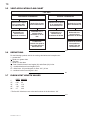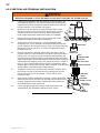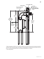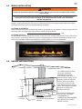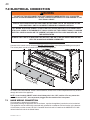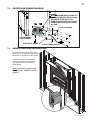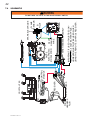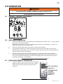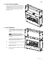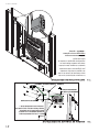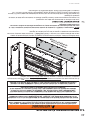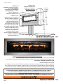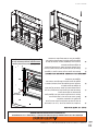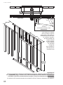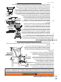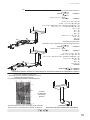
1
1 INSTALLER: LEAVE THIS MANUAL WITH THE APPLIANCE. CONSUMER: RETAIN THIS MANUAL FOR FUTURE REFERENCE. NEVER LEAVE CHILDREN OR OTHER AT RISK INDIVIDUALS ALONE WITH THE APPLIANCE. INSTALLATION AND OPERATING INSTRUCTIONS CERTIFIED UNDER CANADIAN AND AMERICAN NATIONAL STANDARDS: ANSI Z21.50 ● CSA 2.22 FOR VENTED GAS FIREPLACES. LHD50SSN LHD50SSN2 CERTIFIED FOR CANADA AND UNITED STATES USING ANSI/CSA METHODS. SAFETY INFORMATION ! NATURAL GAS WARNING If the information in these instructions are not followed exactly, a fire or explosion may result causing property damage, personal injury or loss of life. LHD50SSP LHD50PSS2 - Do not store or use gasoline or other flammable vapors and liquids in the vicinity of this or any other appliance. - WHAT TO DO IF YOU SMELL GAS: • Do not try to light any appliance. • Do not touch any electrical switch; do not use any phone in your building. • Immediately call your gas supplier from a neighbour’s phone. Follow the gas supplier’s instructions. • If you cannot reach your gas supplier, call the fire department. - Installation and service must be performed by a qualified installer, service agency or the supplier. PROPANE This appliance may be installed in an aftermarket, permanently located, manufactured home (USA only) or mobile home, where not prohibited by local codes. This appliance is only for use with the type of gas indicated on the rating plate. This appliance is not convertible for use with other gases, unless a certified kit is used. LH D5 0SS NI LLU ST RA TE D ! WARNING HOT GLASS WILL CAUSE BURNS. DO NOT TOUCH GLASS UNTIL COOLED. NEVER ALLOW CHILDREN TO TOUCH GLASS. CERTIFIED Wolf Steel Ltd., 24 Napoleon Rd., Barrie, ON, L4M 0G8 Canada / 103 Miller Drive, Crittenden, Kentucky, USA, 41030 Phone (705)721-1212 • Fax (705)722-6031 • www.napoleonfireplaces.com • [email protected] 1.36A W415-0839 / D / 08.15.12 2 TABLE OF CONTENTS 1.0 2.0 3.0 4.0 5.0 6.0 7.0 8.0 9.0 10.0 INSTALLATION OVERVIEW INTRODUCTION 3 4 2.1 2.2 2.3 2.4 2.5 5 6 7 8 9 DIMENSIONS GENERAL INSTRUCTIONS GENERAL INFORMATION RATING PLATE / LIGHTING INSTRUCTION LOCATION SHIPPING HANDLES VENTING 10 3.1 3.2 3.3 3.3.1 3.4 3.5 3.6 3.7 3.8 3.9 10 11 12 12 13 14 14 14 15 17 VENTING LENGTHS AND COMPONENTS FOR DIRECT VENT INSTALLATIONS TYPICAL VENT INSTALLATIONS SPECIAL VENT INSTALLATION PERISCOPE TERMINATION MINIMUM AIR TERMINAL LOCATION CLEARANCES VENT APPLICATION FLOW CHART DEFINITIONS ELBOW VENT LENGTH VALUES HORIZONTAL TERMINATION VERTICAL TERMINATION INSTALLATION 19 4.1 4.1.1 4.1.2 4.2 4.2.1 4.2.2 4.2.3 4.3 4.4 19 20 20 21 21 22 23 23 24 WALL AND CEILING PROTECTION HORIZONTAL INSTALLATION VERTICAL INSTALLATION USING FLEXIBLE VENT COMPONENTS HORIZONTAL AIR TERMINAL INSTALLATION VERTICAL AIR TERMINAL INSTALLATION APPLIANCE VENT CONNECTION MOBILE HOME INSTALLATION GAS INSTALLATION FRAMING 25 5.1 5.2 5.3 5.4 5.5 5.6 26 28 30 33 35 36 TWO SIDED APPLIANCE ONE SIDE APPLIANCE MINIMUM CLEARANCE TO COMBUSTIBLE ENCLOSURES INSTALLING CEMENT BOARD ALCOVE INSTALLATION MINIMUM COMBUSTIBLE MANTEL CLEARANCES FINISHING 37 6.1 6.2 6.3 6.4 37 38 39 39 BEVELLED TRIM REMOVAL DOOR REMOVAL / INSTALLATION MEDIA INSTALLATION UNIQUE INSTALLATIONS ELECTRICAL CONNECTION 40 7.1 7.2 7.3 7.4 40 41 41 42 HARD WIRING CONNECTION RECEPTACLE WIRING DIAGRAM REMOTE RECEIVER INSTALLATION SCHEMATIC OPERATION 43 8.1 8.2 8.3 8.4 8.5 8.6 8.7 8.8 8.9 8.10 8.11 8.12 8.13 8.14 43 43 43 44 44 44 44 45 45 45 46 46 46 46 GENERAL TRANSMITTER LAYOUT APPLIANCE OPERATION HAND HELD REMOTE OPERATIONS TEMPERATURE DISPLAY ROOM THERMOSTAT SMART THERMOSTAT FLAME HEIGHT CHILD PROOF FUNCTION CRYSTALITES LOW BATTERY / MANUAL BYPASS IN THE EVENT OF A POWER FAILURE CONTROL MODULE ANTI CONDENSATION CONTROL SWITCH TIMED BLOWER OPERATING INSTRUCTIONS ADJUSTMENT 47 48 10.1 10.2 10.3 10.4 48 48 49 49 RESTRICTING VERTICAL VENTS PILOT BURNER ADJUSTMENT VENTURI ADJUSTMENT FLAME CHARACTERISTICS NOTE: Changes, other than editorial, are denoted by a vertical line in the margin. W415-0839 / D / 08.15.12 3 11.0 12.0 13.0 14.0 15.0 MAINTENANCE 50 11.1 11.2 11.3 11.4 11.5 11.6 11.7 11.8 11.9 11.10 11.11 11.12 11.13 50 51 51 52 52 52 53 53 54 54 55 55 55 CONTROL ACCESS VALVE TRAIN ASSEMBLY VALVE REMOVAL BURNER REMOVAL CONTROL MODULE REMOVAL IPI BOARD AND AC ADAPTOR ACCESS LAMP REPLACEMENT LENS ASSEMBLY REPLACEMENT PORCELAIN WRAP REMOVAL DOOR LATCH REPLACEMENT GLASS / DOOR REPLACEMENT CARE OF GLASS CARE OF PLATED PARTS REPLACEMENTS TROUBLESHOOTING WARRANTY SERVICE HISTORY 56 59 62 63 1.0 INSTALLATION OVERVIEW See the section “FRAMING MINIMUM MANTEL CLEARANCES” See the section “VENTING - VENTING LENGTHS AND AIR TERMINAL LOCATIONS” See the section “FRAMING MINIMUM CLEARANCE TO COMBUSTIBLE ENCLOSURES” for drywall (or other combustible material)” See the section “FRAMING” GD422R-1 Illustrated See the section “FRAMING” Side Wall See the section “RATING PLATE / LIGHTING INSTRUCTION LOCATION” See the section “ANTI CONDENSATION CONTROL SWITCH” See the section “CONTROL ACCESS” for the control box. See the section “FRAMING MINIMUM CLEARANCE TO COMBUSTIBLE ENSLOSURES” for noncombustible materials such as tile, marble, granite, etc. Important: Extra support may be required See the section “REMOTE RECEIVER INSTALLATION”. W415-0839 / D / 08.15.12 4 2.0 INTRODUCTION ! • • • • • • • • • • • • • • • • • • • • • • • • • • • • • WARNING THIS APPLIANCE IS HOT WHEN OPERATED AND CAN CAUSE SEVERE BURNS IF CONTACTED. ANY CHANGES OR ALTERATIONS TO THIS APPLIANCE OR ITS CONTROLS CAN BE DANGEROUS AND IS PROHIBITED. Do not operate appliance before reading and understanding operating instructions. Failure to operate appliance according to operating instructions could cause fire or injury. Risk of fire or asphyxiation do not operate appliance with fixed glass removed. Do not connect 110 volts to the control valve. Risk of burns. The appliance should be turned off and cooled before servicing. Do not install damaged, incomplete or substitute components. Risk of cuts and abrasions. Wear protective gloves and safety glasses during installation. Sheet metal edges may be sharp. Do not burn wood or other materials in this appliance. Children and adults should be alerted to the hazards of high surface temperature and should stay away to avoid burns or clothing ignition. Young children should be carefully supervised when they are in the same room as the appliance. Toddlers, young children and others may be susceptible to accidental contact burns. A physical barrier is recommended if there are at risk individuals in the house. To restrict access to an appliance, install an adjustable safety gate to keep toddlers, young children and other at risk individuals out of the room and away from hot surfaces. Clothing or other flammable material should not be placed on or near the appliance. Due to high temperatures, the appliance should be located out of traffic and away from furniture and draperies. Ensure you have incorporated adequate safety measure to protect infants/toddlers from touching hot surfaces. Even after the appliance is out, the glass and/or screen will remain hot for an extended period of time. Check with your local hearth specialty dealer for safety screens and hearth guards to protect children from hot surfaces. These screens and guards must be fastened to the floor. Any safety screen or guard removed for servicing must be replaced prior to operating the appliance. The appliance is a vented gas-fired appliance. Do not burn wood or other materials in the appliance It is imperative that the control compartments, burners and circulating blower and its passageway in the appliance and venting system are kept clean. The appliance and its venting system should be inspected before use and at least annually by a qualified service person. More frequent cleaning may be required due to excessive lint from carpeting, bedding material, etc. The appliance area must be kept clear and free from combustible materials, gasoline and other flammable vapors and liquids. Under no circumstances should this appliance be modified. This appliance must not be connected to a chimney flue pipe serving a separate solid fuel burning appliance. Do not use this appliance if any part has been under water. Immediately call a qualified service technician to inspect the appliance and to replace any part of the control system and any gas control which has been under water. Do not operate the appliance with the glass door removed, cracked or broken. Replacement of the glass should be done by a licensed or qualified service person. Do not strike or slam shut the appliance glass door. When equipped with pressure relief doors, they must be kept closed while the appliance is operating to prevent exhaust fumes containing carbon monoxide, from entering into the home. Temperatures of the exhaust escaping through these openings can also cause the surrounding combustible materials to overheat and catch fire. Only doors / optional fronts certified with the appliance are to be installed on the appliance. Keep the packaging material out of reach of children and dispose of the material in a safe manner. As with all plastic bags, these are not toys and should be kept away from children and infants. As with any combustion appliance, we recommend having your appliance regularly inspected and serviced as well as having a Carbon Monoxide Detector installed in the same area to defend you and your family against Carbon Monoxide. Ensure clearances to combustibles are maintained when building a mantel or shelves above the appliance. Elevated temperatures on the wall or in the air above the appliance can cause melting, discolouration or damage of decorations, a T.V. or other electronic components. 3.2B W415-0839 / D / 08.15.12 5 2.1 DIMENSIONS Two sided 20” 40” SHIPPING HEIGHT 60” EXTENDED HEIGHT 37 3/16” ACCESS SIDE 36” 16 1/4” 28” ELECTRICAL INLET GAS INLET 13 1/2” ELECTRICAL INLET 5” 8” GAS INLET 15” 13 1/2” 50 1/4” 67 3/8” One side 20” 40” SHIPPING HEIGHT 60” EXTENDED HEIGHT 37 3/16” ACCESS SIDE 36” GAS INLET 28” ELECTRICAL INLET 5” 16 1/4” ELECTRICAL INLET 17 1/2” 23 1/2” 24 1/4” 6” 8” 23 1/2” GAS INLET 50 1/4” 67 3/8” W415-0839 / D / 08.15.12 6 2.2 GENERAL INSTRUCTIONS ! WARNING ALWAYS LIGHT THE PILOT WHETHER FOR THE FIRST TIME OR IF THE GAS SUPPLY HAS RUN OUT, WITH THE GLASS DOOR OPENED OR REMOVED. PROVIDE ADEQUATE CLEARANCE FOR SERVICING AND OPERATING THE APPLIANCE. PROVIDE ADEQUATE VENTILATION. NEVER OBSTRUCT THE FRONT OPENING OF THE APPLIANCE. OBJECTS PLACED IN FRONT OF THE APPLIANCE MUST BE KEPT A MINIMUM OF 48” FROM THE FRONT FACE OF THE APPLIANCE. SURFACES AROUND AND ESPECIALLY ABOVE THE APPLIANCE CAN BECOME HOT. AVOID CONTACT WHEN THE APPLIANCE IS OPERATING. FIRE RISK. EXPLOSION HAZARD. HIGH PRESSURE WILL DAMAGE VALVE. DISCONNECT GAS SUPPLY PIPING BEFORE PRESSURE TESTING GAS LINE AT TEST PRESSURES ABOVE 1/2 PSIG. CLOSE THE MANUAL SHUT-OFF VALVE BEFORE PRESSURE TESTING GAS LINE AT TEST PRESSURES EQUAL TO OR LESS THAN 1/2 PSIG. USE ONLY WOLF STEEL APPROVED OPTIONAL ACCESSORIES AND REPLACEMENT PARTS WITH THIS APPLIANCE. USING NON-LISTED ACCESSORIES (BLOWERS, DOORS, LOUVRES, TRIMS, GAS COMPONENTS, VENTING COMPONENTS, ETC.) COULD RESULT IN A SAFETY HAZARD AND WILL VOID THE WARRANTY AND CERTIFICATION. THIS GAS APPLIANCE SHOULD BE INSTALLED AND SERVICED BY A QUALIFIED INSTALLER to conform with local codes. Installation practices vary from region to region and it is important to know the specifics that apply to your area, for example in Massachusetts State: • This product must be installed by a licensed plumber or gas fitter when installed within the commonwealth of Massachusetts. • The appliance damper must be removed or welded in the open position prior to installation of an appliance insert or gas log. • The appliance off valve must be a “T” handle gas cock. • The flexible connector must not be longer than 36 inches. • A Carbon Monoxide detector is required in all rooms containing gas fired appliances. • The appliance is not approved for installation in a bedroom or bathroom unless the unit is a direct vent sealed combustion product. The installation must conform with local codes or, in absence of local codes, the National Gas and Propane Installation Code CSA B149.1 in Canada, or the National Fuel Gas Code, ANSI Z223.1 / NFPA 54 in the United States. Suitable for mobile home installation if installed in accordance with the current standard CAN/CSA Z240MH Series, for gas equipped mobile homes, in Canada or ANSI Z223.1 and NFPA 54 in the United States. We suggest that our gas hearth products be installed and serviced by professionals who are certified in the U.S. by the National Fireplace Institute® (NFI) as NFI Gas Specialists As long as the required clearance to combustibles is maintained, the most desirable and beneficial location www.nficertified.org for an appliance is in the center of a building, thereby allowing the most efficient use of the heat created. The location of windows, doors and the traffic flow in the room where the appliance is to be located should be considered. If possible, you should choose a location where the vent will pass through the house without cutting a floor or roof joist. If the appliance is installed directly on carpeting, vinyl tile or other combustible material other than wood flooring, the appliance shall be installed on a metal or wood panel extending the full width and depth. Some appliances have optional fans or blowers. If an optional fan or blower is installed, the junction box must be electrically connected and grounded in accordance with local codes, use the current CSA C22.1 Canadian Electrical Code in Canada or the ANSI/NFPA 70 National Electrical code in the United States. 4.1A W415-0839 / D / 08.15.12 7 2.3 GENERAL INFORMATION FOR YOUR SATISFACTION, THIS APPLIANCE HAS BEEN TEST-FIRED TO ASSURE ITS OPERATION AND QUALITY! LHD50 NG LP Altitude (FT) 0-4,500 0-4500 Max. Input (BTU/HR) 30,000 30,000 Max. Output (BTU/HR) 24,000 24,000 79% 79% Min. Inlet Gas Supply Pressure 4.5" Water Column 11" Water Column Max. Inlet Gas Supply Pressure 7" Water Column 13" Water Column 3.5" Water Column 10" Water Column Efficiency Manifold Pressure (Under Flow Conditions) When the appliance is installed at elevations above 4,500ft, and in the absence of specific recommendations from the local authority having jurisdiction, the certified high altitude input rating shall be reduced at the rate of 4% for each additional 1,000ft. Expansion / contraction noises during heating up and cooling down cycles are normal and are to be expected. Change in flame appearance from “HI” to “LO” is more evident in natural gas than in propane. This appliance is approved for bathroom, bedroom and bed-sitting room installations and is certified for mobile home installation. This appliance is only for use with the type of gas indicated on the rating plate. This appliance is not convertible for use with other gases, unless a certified kit is used. There are two switches that control the function of the appliance. One on the receiver that must be placed in the middle position. The other is on the control module that must be in the “I” position, which denotes on. If these switches aren’t in these locations the appliance will not work, see “REMOTE RECEIVER INSTALLATION” and “CONTROL MODULE” section. NOTE: The protective wrap on plated parts is best removed when the assembly is at room temperature but this can be improved if the assembly is warmed, using a hair dryer or similar heat source. This appliance is equipped with a remote control system, which requires batteries (supplied) to be installed. The transmitter takes 3 “AAA” batteries and in the case of a power failure the receiver takes 4 “AA” batteries. W415-0839 / D / 08.15.12 8 RATING PLATE / LIGHTING INSTRUCTION LOCATION ! WARNING ALLOW THE APPLIANCE TO COOL BEFORE PERFORMING ANY MAINTENANCE OR CLEANING. Both the rating plate and lighting instructions are attached to a key chain and inserted in a mail slot on the left side of the appliance (access side). It is recommended to remove the door prior to instruction removal. Using your fingers or a tool such as a screw driver or pencil, gently pull both chains toward you. With the chain at the bulb end of the slot, wiggle the rating plate out being careful not to tear the instructions as they pass through the slot. To replace, slide the instructions and the chain back through the slot and re-attach the door (if removed). WARNING: IMPROPER INSTALLATION, ADJUSTMENT, ALTERATION, SERVICE OR MAINTENANCE CAN CAUSE PROPERTY DAMAGE, PERSONAL INJURY OR LOSS OF LIFE. REFER TO OWNER’S MANUAL. INSTALLATION AND SERVICE MUST BE PERFORMED BY A QUALIFIED INSTALLER, SERVICE AGENCY OR THE GAS SUPPLIER. ATTENTION: UN INSTALLATION OU UNE MODIFICATION INAPPROPRIEE DU REGLAGE, DU SERVICE ET DE L’ENTRETIEN POURRAIENT ETRE LA CAUSE DE DOMMAGES A LA PROPRIETE DE BLESSURES CORPORELLES OU MEME LA MORT. CONSULTER LE MANUEL D’INFORMATION, L’INSTALLATION ET LE SERVICE DOIVENT ETRE EXECUTES PAR UN INSTALLATEUR QUALIFIE POUR LE AZ, UNE ENTREPRISE DE SERVICE OU LE FOURNISSEUR DE GAZ SEULEMENT. CAUTION: HOT WHILE OPERATING. DO NOT TOUCH. KEEP CHILDREN, CLOTHING, FURNITURE, GASOLINE OR OTHER FLAMMABLE VAPORS AWAY. AVERTISSEMENT: L’APPAREIL EST CHAUD PENDANT SON FONCTIONNEMENT. LES ENFANTS, LES VETEMENTS, LES MEUBLES, L’ESSENCE ET AUTRES LIQUIDES QUI EMETTENT DES GAZ VOLATILS INFLAMMABLES DOIVENT ETRE TENUS ELOIGNES DE L’APPAREIL. “This appliance is only for use with the type(s) (s) of gas indicated on the rating plate and may be installed in an aftermarket, permanently located, manufactured home (USA only) or mobile home, where not prohibited by local codes. See owner’s manual ual for fo details. This appliance is supplied with a conversion kit.” conve FOR YOUR SAFETY: DO NOT STORE OR USE GASOLINE OR OTHER FLAMMABLE VAPORS AND LIQUIDS IN VICINITY OF THIS OR ANY OTHER APPLIANCE. CAUTION: O DO NOT OPERATE THE FIREPLACE REPLAC WITH THE GLASS REMOVED, CRACKED OR BROKEN. MOVED, CRA REPLACEMENT OF O THE GLASS SHOULD BE DONE BY A LICENSED PERSON. OR QUALIFIED PERSO POUR VOTRE SECURITE: A M P LE KEEP BURNER AND CONTROL COMPARTMENT CLEAN. SEE INSTALLATION AND OPERATING INSTRUCTIONS MANUAL. APPLIANCE NEEDS FRESH AIR FOR SAFE OPERATION AND MUST BE INSTALLED WITH ADEQUATE PROVISIONS FOR COMBUSTION AND VENTILATION AIR. GARDEZ LE BRULEUR ET LE COMPARTIMENT DES CONTROLES PROPRES. CONSULTEZ LE MANUEL D’INFORMATION ET D’INSTALLATION. PAR MESURE DE SECURITE. CET APPAREIL DOIT ETRE ALIMENTE EN AIR FRAIS ET AVEC SUFFISANT D’AIR COMBURANTET DE VENTILATION. «Cet appareil doit être re utilisé uniquement uniquem iqués sur la plaque plaqu avec les types de gaz indiqués signalétique que et peut être installé dans une maison on préfabriquée (É.-U. seulement) ou mobile bile installée à demeure si les règlements locaux le permettent. Voir la notice de l’utilisateur pour plus de renseignements. Une trousse de conversion es est fournie avec cet appareil.» appar NE PAS ENTREPOSER NI UT UTILISER SSENCE NI D’AUTRES VAPEURS D’ESSENCE OU LIQUIDES INFLAM INFLAMMABLES ANS LE VOISINAG VOISINAGE DE CET AREIL OU D APPAREIL DE TOUT AUTRE PP APPAREIL. AVERTISSEMENT: NE PAS AVERTIS UTILISER L’APPAREIL SI LE UTILI PANNEAU FRONTAL EN VERRE PAN N’ES N’EST PAS EN PLACE, EST CRAQUÉ OU BRISÉ. CONFIEZ LE REMPLACEMENT DU PANNEAU À UN TECHNICIEN AGRÉÉ. CERTIFIED UNDER ER / HOMOLOGUE SELON ELON LES NORMES: ANSI Z21.50 - 2007 • CSA 2.22 - 2007 VENTED GAS FIREPLACE / FOYER AU GAZ VENTILÉ VENTED GAS FIREPLACE. EPLACE PLAC . APPROVED FOR BEDROOM, OOM, BATHROOM BATHROOM AND BED-S BED-SITTING D-SIITT TTIING ROOM INSTALLATION. SUITABLE FOR MOBILE HOME INSTALLATION IF INSTALLED IN ACCORDANCE WITH THE NDARD DARD CAN CAN/ /CS CSA A Z240MH SERIES GASS EEQUIPPED QUIPPED MO MOB BILE L HOMES CURRENT STANDARD CAN/CSA MOBILE HOMES, IN CANADA OR IN THE UNITED STATES THE MANUFACTURED HOME CONSTRUCTION AND SAFETY STANDARD, TITLE 24 280. 80. WHEN TH THI IS US SSTANDARD TANDARD AND IS NOT APPL LICABLE USE THE STAN T CFR, PART 3280. THIS APPLICABLE STANDARD FOR FIRE SAFETY CRITERIA FOR MANUFACTURED HOME INSTALLATIONS, SITES AND COMMUNITIES, ANSI / NFPA YER ER DE CHAUFFAGE CHAUFFFAGE AU GAZ CHAUF GAZ AVEC AVEC ÉVACUATION. ÉVACU V A ION. HOMOLOGUÉ AT HOMO OMOLLOG OGUÉ UÉ PPOUR O INSTALLATION DANS UNE CHAMBRE À COUCHER, UNE SALLE DE BAIN ET UN STUDIO. APPROPRIÉ POUR INSTALLATION DANS 501A. FOYER ON MO MOB BILE SSII SSON ON INS IINSTALLATION NSTTALLATIO ION NC ONF NFORME AUX EX EXIG IGENCES ENCE DE LA NORME CAN/CSA Z240MH SÉRIE DE MAISONS MOBILES ÉQUIPÉES AU GAZ, EN VIGUEUR AU CANADA OU AUX ÉTATS-UNIS UNE MAISO MAISON MOBILE CONFORME EXIGENCES A NORME N NORM ME DE SECURITÉ SECURIITÉ ET DE CONSTRUCTION SECUR CONSTRUCT NSTRUCTIO ION N DE MAISONS MAISONSS MANUFACTURÉES, MAN MA TITRE 24 CFR, SECTION 3280. DANS LE CAS OU CETTE NORME D'ÉTATS-UNIS NE PEUT ÊTRE APPLIQUÉE, SE RÉFÉRER CERTIFIED FOR / CERTIFIEE DE LA RELA REL A T I VE CR R I TÈRE M ESURES SÉCURI SÉCUR I T TÉ CO A LA NORME RELATIVE AU CRITÈRE DE MESURES DE SÉCURITÉ CONTRE L'INCENDIE POUR LES INSTALLATIONS DANS LES MAISONS MANUFACTURÉS, LES SITES ET LES COMMUNAUTÉS, ANSI/NFPA 501A. POUR CANADA / USA CE MUST BE INSTALLED IN ACCORDANCE WITH LOCAL L THIS APPLIANCE CODES, IF ANY; IF NONE, FOLLOW THE CURRENT ANSI Z223.1, OR CSA B149, INSTALLATION CODES./INSTALLER L’APPAREIL SELON REFERENCE # 161746 LES CODES OU RÈGLEMENTS LOCAUX, OU EN L’ABSENCE D DE TELS RÈGLEMENTS, SELON LES CODES D’INSTALLATION ANSI Z223.1 OU CSA-B149 EN VIGUER. CERTIFIED CERTIFIED AU GAZ UNDER / HOMOLOGUE ET VENTILÉ SELON VENTED LES NORMES: GAS CURRENT FIREPLACE CSA 2.33b HEATER. PART 3280.STANDARD CAN/CSA APPROVED - 2008, ANSI FOR Z240MH FOYER DE WHEN THIS US Z21.88bSERIES BEDROOM, 2008 VENTED MAISON CHAUFFAGE AUSTANDARD IS NOT GAS EQUIPPEDBATHROOM MOBILE GAZ AVEC APPLICABLE MOBILE AND BED-SITTING GAS FIREPLACE NORME SI SON INSTALLATION ÉVACUATION. HOMES, DE USE THE ROOM IN RELATIVE SECURITÉ ET HEATER CONFORME HOMOLOGUÉ STANDARD FORCANADA OR IN INSTALLATION. AU CRITÈRE DE CONSTRUCTION / APPAREIL SUITABLE POUR INSTALLATION FIRE SAFETY THE UNITED AUX EXIGENCES DE MESURES DE MAISONS DE CHAUFFAGE CRITERIA STATES THE FOR MOBILE DE LA NORME DE SÉCURITÉ DANS HOME INSTALLATION MANUFACTURED FOR MANUFACTURED MANUFACTURÉE CAN/CSA UNE CHAMBRE ALIMENTÉ CONTRE HOME CONSTRUCTION À COUCHER, Z240MH L'INCENDIE S, TITRE 24 IF INSTALLED HOME INSTALLATIONS, CFR, SECTIONSÉRIE DE MAISONS UNE SALLE POUR LES IN ACCORDANCE AND SAFETY INSTALLATIONS DE BAIN 3280. DANS SITES MOBILES STANDARD, WITH THE LE CAS ÉQUIPÉES ET UN STUDIO. AND COMMUNITIES, DANS LES TITLE 24 APPROPRIÉ MAISONS OU CETTE NORME AU GAZ, EN ANSI / NFPA CFR, MANUFACTURÉS D'ÉTATS-UNISVIGUEUR LHD50NT POUR INSTALLATION : DO 501A. TO THE AU APPLIANCE,NOT ADD ANY , LES SITES NE PEUT CANADA OU DANS UNE IN CONTACT AUX ÉTATS-UNIS ÊTRE APPLIQUÉE, WHICH WILL MATERIAL ET LES COMMUNAUTÉS, 0-4500FT (0-1370M) THAN THAT WITH THE FLAMES, COME SE RÉFÉRER DE LA LHD50PT SUPPLIED ANSI/NFPA 30,000 BTU/H MANUFACTURER A LA NORME ALTITUDE BY THE OTHER UN COMBUSTI 501A. / ÉLÉVATION MINIMUM 23,000 BTU/H WITH THE INPUT / 3.5" WATER CLEARANCE APPLIANCE. ALIMENTATION DOIT PAS BLE SOLIDE REDUCED COMBUSTIBLE COLUMN/D'UNE 0-4500FT INPUT / ALIMENTATION TO ÊTRÉ UTILISÉ (0-1370M) TOP COLONNE #38 MATERIALS: NE CET APPAREIL. 4.5" WATER ORIFICE D'EAU RÉDUITE 30,000 BTU/H FLOOR / COLUMN/D'UNE LES PORTES UTILISERAVEC 23,000 BTU/H MANIFOLD INJECTEUR RECESSED 0” COLONNE PRESSION PRESSURE #53 7.0" WATER HOMOLOG VITRÉES AVEC D'EAU RECESSED DEPTH ONE / COLUMN/D'UNE SIDED 0” MINIMUM AU COLLECTEUR 10" WATER UÉES SEULEMEN FRAMING DEPTH SEE 23" AVEC CETTE COLUMN/D'UNE COLONNE PRESSION SUPPLY PRESSURE THRU 13.5” (NOT INCLUDING FACE MATERIAL) D'EAU D'ALIMENTATION UNITÉ. COLONNE T / THE MAXIMUM SIDES APPLIANCE D'EAU AVERTISSE MINIMALE 11" WATER COLUMN/D'UNE SUPPLY PRESSION NAPOLEON MUST BE VENT PRESSURE CET APPAREIL MENT: D'ALIMENTATION VENTED VENT COLONNE / BACK USING THE FOR VENTINGKITS. SEE 0” ENTRER AUCUN N'AJOUTEZ D'EAU MAXIMALE 13" WATER COLUMN/ OWNERS PAS A APPROPRIATE MATÉRIAU RESEALING SPECIFICS. MANTLE 2" AUTRE EN CONTACT D'UNE COLONNE IS NECESSARY PROPERINSTALLATION AVEC LES DEVANT QUE CELUI TOP, SIDES MANUAL L'APPAREIL 0” CET APPAREIL REINSTALLATIO FLAMMES QUI AFTER SERVICING D'EAU DOIT & BACK: SEE OWNERS 15" * DÉGAGEMENPAR LE EST FOURNI AVEC N AND D'ÉVACUATION ÉVACUER SES PER FABRICANT. THE VENT-AIR D'INSTALLATIONPROPRE GAZ * MAXIMUM MANUAL STAND OFF SPACERS MATÉRIAUX TS MINIMAUX A NAPOLEON.EN UTILISANT INTAKE HORIZONTAL DE PROPRIÉTAIRE HORIZONTALE SYSTEM. PRÉCISE. IL FOR FRAMING COMBUSTIBL DES RÉFÉRER L'ENSEMBLE DESSUS EST IMPORTANT EXTENSION RESCELLER AU MANUEL POUR L'ÉVACUATION MATERIALS. SEE OWNER'S MAXIMALE: ES: PROFONDEUR / L'EXTENSION SYSTÉME L'ÉVENT APRÈS DE BIEN RÉINSTALLER FOR FINISHING INSTRUCTION2". SEE INSTRUCTION D'ENCASTRÉ PLANCHER DE PRISE 0” MATERIALS MANUAL D'AIR. AVOIR ASSURÉ ET ÉVENT MANUAL LE MAINTIEN 25" FOR MINIMUM FOR GREATER DESSUS, CÔTES ELECTRICAL DU AND MAXIMUM 0” EXTENSIONS. SELON COTÉS & ARRIÈRE: RATING: MANTEAU LE MANUEL MADE IN 115V 0.82AMP, VENT LENGTHS. 2" SELON * L'EXTENSION ARRIÉRE CANADA DE PROPRIÉTAIRE LES ESPACEURS WOLF STEEL 60HZ 0” / FABRIQUÉ HORIZONTALE PLUS GRANDES. DE DÉGAGEMENT POUR LTD. BARRIE, AU CANADA 15" * RÉFÉRER MAXIMALE: LES MATÉRIAUX ONTARIO, POUR 0” AU MANUEL 2". RÉFÉRER DE FINITION. LES MATÉRIAUX CANADA D'INSTALLATIONAU MANUEL D'OSSATURE SERIAL D'INSTRUCTION DE PROPRIÉTAIRE. NUMBER/N POUR DES EXTENSIONS O. DE REFERENCE W/N 16131 # NOT FOR USE WITH SOLID FUEL. WITH GLASS FOR USE CERTIFIED DOORS UNIT ONLY. WITH THIS WARNING MODEL NATURAL GAS / GAZ NATURAL MODEL SÉRIE: PROPANE LHD50 CLASSIFICATIO N: 115V 0.82AMP, 60HZ W385-0448 NOT FOR USE WITH MODEL MODE EL NATURAL NA N ATURAL GAS / SOLID FUEL. FOR USE GAZ NA NATURAL N ATURAL T WITH GLASS SS DOORS LHD50N LHD50 CERTIFIED ED WITH THIS UNIT ONLY. NLY. 00-4500FT (0-1370M) WARNING NIING: DO NOT N ADD AN ANYY M MATERIAL ATERIAL 30,000 BTU/H TO THE APPLIANCE, WHICH WIL WILLL COME IN N CONTACT TACT WITH THE FLAMES, OTHER AN TH HAT SUPPLIED B THAN THAT BYY THE UFACTURER F CTURER WITH THE APPLIANCE. APPLIAN MANUFACTURER CLHD50N MINIMUM M CLEARANCE TTO O TIBLE LE MATERIALS: MA MATERIALS: COMBUSTIBLE CLHD50P ALTITUDE / ÉLÉVATION INPUT / ALIMENTATION 20,000 BTU/H REDUCED INPUT / ALIMENTATION RÉDUITE #38 ORIFICE / INJECTEUR ATER T COL 3.5" W WATER COLUMN/D'UNE COLONNE D'EAU MANIFOLD PRESSURE / PRESSION AU COLLECTEUR AT COLUMN/D'UNE COLONNE D'EAU 4.5" W WATER MINIMUM SUPPLY PRESSURE / PRESSION D'ALIMENTATION MINIMALE 7.0 WATER COLUMN/D'UNE COLONNE D'EAU 7.0" MAXIMUM SUPPLY PRESSURE / PRESSION D'ALIMENTATION MAXIMALE S 2.4 TOP 0” 0” FLOOR RECESSED DEPTH ONE SIDED 23.75" EE THRU 13.5” RECESSED DEPTH SEE THE APPLIANCE MUST BE VENTED USING THE APPROPRIATE DING G FRAMING (NOT INCLUDING NAPOLEON VENT KITS. SEE OWNERS INSTALLATION MANUAL FACE MATERIAL) FOR VENTING SPECIFICS. PROPER REINSTALLATION AND SIDES 0” RESEALING IS NECESSARY AFTER SERVICING THE VENT-AIR BACK 0” INTAKE SYSTEM. VENT TOP 3” VENT SIDES & BOTTOM 2” VERTICAL VENT 2” MANTLE 18” * TOP, SIDES & BACK: PER STAND OFF SPACERS FOR FRAMING MATERIALS. FOR FINISHING MATERIALS SEE OWNERS MANUAL * MAXIMUM HORIZONTAL EXTENSION / L'EXTENSION HORIZONTALE MAXIMALE: 2". SEE INSTRUCTION MANUAL FOR GREATER EXTENSIONS. SEE OWNER'S INSTRUCTION MANUAL FOR MINIMUM AND MAXIMUM VENT LENGTHS. ELECTRICAL RATING: 115V.60HZ. LESS THAN 12 AMPERES MADE IN CANADA / FABRIQUÉ AU CANADA WOLF STEEL LTD. BARRIE, ONTARIO, CANADA MODEL PROPANE/ PROPANE MODÈLE LHD50P 0-4500FT (0-1370M) 30,000 BTU/H 20,000 BTU/H #53 10" WATER COLUMN/D'UNE COLONNE D'EAU 11" WATER COLUMN/D'UNE COLONNE D'EAU 13" WATER COLUMN/ D'UNE COLONNE D'EAU UN COMBUSTIBLE SOLIDE NE DOIT PAS ÊTRÉ UTILISÉ AVEC CET APPAREIL. UTILISER AVEC LES PORTES VITRÉES HOMOLOGUÉES SEULEMENT AVEC CETTE UNITÉ. AVERTISSEMENT: N'AJOUTEZ PAS A CET APPAREIL AUCUN MATÉRIAU DEVANT ENTRER EN CONTACT AVEC LES FLAMMES AUTRE QUE CELUI QUI EST FOURNI AVEC CET APPAREIL PAR LE FABRICANT. DÉGAGEMENTS MINIMAUX DES MATÉRIAUX COMBUSTIBLES: DESSUS 0" PLANCHER 0" PROFONDEUR DE L’ENCLAVE FACE UNIQUE 23.75" PROFONDEUR DE L’ENCLAVE BINAIRE 13.5" OSSATURE (MATÉRIAU DE FAÇADE NON COMPRIS) CÔTÉS 0" DESSUS, COTÉS & ARRIÈRE: SELON LES ESPACEURS DE ARRIÈRE 0" DÉGAGEMENT POUR LES MATÉRIAUX D'OSSATURE SELON LA 3" MANUEL DE PROPRIÉTAIRE POUR LES MATÉRIAUX DE FINITION. DESSUS DU CONDUIT D’ÉVENT CÔTÉS ET DESSOUS DU CONDUIT * L'EXTENSION HORIZONTALE MAXIMALE: 2". RÉFÉRER AU 2" MANUEL D'INSTRUCTION POUR DES EXTENSIONS PLUS GRANDES. D’ÉVENT CONDUIT D’ÉVENT VERTICAL 2" RÉFÉRER AU MANUEL D'INSTALLATION DE PROPRIÉTAIRE. TABLETTE 18" * L'APPAREIL DOIT ÉVACUER SES GAZ EN UTILISANT L'ENSEMBLE D'ÉVACUATION PROPRE A NAPOLEON. RÉFÉRER AU MANUEL D'INSTALLATION DE PROPRIÉTAIRE POUR L'ÉVACUATION PRÉCISE. IL EST IMPORTANT DE BIEN RÉINSTALLER ET RESCELLER L'ÉVENT APRÈS AVOIR ASSURÉ LE MAINTIEN DU SYSTÉME DE PRISE D'AIR. SERIAL NUMBER/NO. DE SÉRIE: LHD50 SPÉCIFICATIONS ÉLECTRIQUES : 115 V, 60 HZ. MOINS DE 12 AMPÈRES. W385-0448 / B INSTALLER: It is your responsibility to check off the appropriate box on the rating plate according to the model, venting and gas type of the appliance. This illustration is for reference only. Refer to the rating plate on the appliance for accurate information. NOTE: The rating plate must remain with the appliance at all times. It must not be removed. W415-0839 / D / 08.15.12 9 2.5 SHIPPING HANDLES IMPORTANT This appliance fully dressed weighs 300 lbs. A. Lift up and secure the framing kit, see “STEEL STUD FRAMING KIT” section for instructions. B. Insert the shipping handles (not supplied) by placing the tabs in the desired slots on both sides of the appliance and lifting upwards to secure in place. C. Remove handles once the appliance is in its preferred location. Use shipping brackets to secure base of appliance. W415-0839 / D / 08.15.12 10 3.0 VENTING ! WARNING RISK OF FIRE, MAINTAIN SPECIFIED AIR SPACE CLEARANCES TO VENT PIPE AND APPLIANCE. IF VENTING IS INCLUDED WITH SPACERS THE VENT SYSTEM MUST BE SUPPORTED EVERY 3 FEET FOR BOTH VERTICAL AND HORIZONTAL RUNS. USE SUPPORTS OR EQUIVALENT NON-COMBUSTIBLE STRAPPING TO MAINTAIN THE REQUIRED CLEARANCE FROM COMBUSTIBLES. USE WOLF STEEL LTD. SUPPORT RING ASSEMBLY W010-0370 OR EQUIVALENT NON-COMBUSTIBLE STRAPPING TO MAINTAIN THE MINIMUM CLEARANCE TO COMBUSTIBLES FOR BOTH VERTICAL AND HORIZONTAL RUNS. SPACERS ARE ATTACHED TO THE INNER PIPE AT PREDETERMINED INTERVALS TO MAINTAIN AN EVEN AIR GAP TO THE OUTER PIPE. THIS GAP IS REQUIRED FOR SAFE OPERATION. A SPACER IS REQUIRED AT THE START, MIDDLE AND END OF EACH ELBOW TO ENSURE THIS GAP IS MAINTAINED. THESE SPACERS MUST NOT BE REMOVED. THIS APPLIANCE USES A 5” EXHAUST / 8” AIR INTAKE VENT PIPE SYSTEM. Refer to the section applicable to your installation. For safe and proper operation of the appliance follow the venting instruction exactly. Deviation from the minimum vertical vent length can create difficulty in burner start-up and/or carboning. Under extreme vent configurations, allow several minutes (5-15) for the flame to stabilize after ignition. Provide a means for visually checking the vent connection to the appliance after the appliance is installed. Use a firestop, vent pipe shield or attic insulation shield when penetrating interior walls, floor or ceiling. NOTE: If for any reason the vent air intake system is disassembled; reinstall per the instructions provided for the initial installation. NOTE: This appliance must be installed with a continuous connection of exhaust and air intake vent pipes. Utilizing alternate constructions such as a chimney as part of the vent system is not permitted. 7.2B 3.1 VENTING LENGTHS AND COMPONENTS FOR DIRECT VENT INSTALLATIONS Use only Wolf Steel, Simpson Dura-Vent, Selkirk Direct Temp, American Metal Amerivent or Metal-Fab venting components. Minimum and maximum vent lengths, for both horizontal and vertical installations, and air terminal locations for either system are set out in this manual and must be adhered to. For Simpson DuraVent, Selkirk Direct Temp, American Metal Amerivent and Metal-Fab follow the installation procedure provided with the venting components. A starter adaptor must be used with the following vent systems and may be purchased from the corresponding supplier: PART 5”/8” SUPPLIER WEBSITE Duravent W175-0170 Wolf Steel www.duravent.com Amerivent 5DSC-N2 American Metal www.americanmetalproducts.com Direct Temp 5DT-AA Selkirk www.selkirkcorp.com SuperSeal 5DDA Metal-Fab www.mtlfab.com For Simpson Dura-Vent, Selkirk Direct Temp, American Metal Amerivent and Metal-Fab follow the installation procedure found on the website for your venting supplier. For vent systems that provide seals on the inner exhaust flue, only the outer air intake joints must be sealed using a red high temperature silicone (RTV). This same sealant may be used on both the inner exhaust and outer intake vent pipe joints of all other approved vent systems except for the exhaust vent pipe connection to the appliance flue collar which must be sealed using the black high temperature sealant Mill Pac. W415-0839 / D / 08.15.12 11 When using Wolf Steel venting components, use only approved Wolf Steel rigid / flexible components with the following termination kits: wall terminal kit GD422-1, GD422R-1, or 1/12 to 7/12 pitch roof terminal kit GD410, 8/12 to 12/12 roof terminal kit GD411, flat roof terminal kit GD412 or periscope kit GD401 (for wall penetration below grade). With flexible venting, in conjunction with the various terminations, use either the 5 foot vent kit GD420 or the 10 foot vent kit GD430. For optimum flame appearance and appliance performance, keep the vent length and number of elbows to a minimum. The air terminal must remain unobstructed at all times. Examine the air terminal at least once a year to verify that it is unobstructed and undamaged. Rigid and flexible venting systems must not be combined. Different venting manufacturer components must not be combined. These vent kits allow for either horizontal or vertical venting of the appliance. The maximum allowable horizontal run is 20 feet. The maximum allowable vertical vent length is 40 feet. The maximum number of vent connections is two horizontally or three vertically (excluding the appliance and the air terminal connections) when using flexible venting. Horizontal runs may have a 0” rise per foot however for optimum performance it is recommended that all horizontal runs have a minimum 1/4” rise per foot using flexible venting. For safe and proper operation of the appliance, follow the venting instructions exactly. A terminal shall not terminate directly above a sidewalk or paved driveway which is located between two single family dwellings and serves both dwellings. Local codes or regulations may require different clearances. Do not allow the inside liner to bunch up on horizontal or vertical runs and elbows. Keep it pulled tight. A 1¼” air gap all around between the inner liner and outer liner is required for safe operation. 8.3 3.2 TYPICAL VENT INSTALLATIONS 16” MINIMUM 24” MAXIMUM 40 FEET MAXIMUM 3 FEET MINIMUM 15” MINIMUM 36” 51” MINIMUM PLUS RISE* 36” * See “VENTING” section. W415-0839 / D / 08.15.12 12 3.3 SPECIAL VENT INSTALLATION 3.3.1 PERISCOPE TERMINATION Use the periscope kit to locate the air termination above grade. The periscope must be installed so that when final grading is completed, the bottom air slot is located a minimum 12” above grade. The maximum allowable vent length is 10’ for a fireplace and 8’ for a stove. 12” MIN TO GRADE 30” MIN 36” 9.1A W415-0839 / D / 08.15.12 13 3.4 MINIMUM AIR TERMINAL LOCATION CLEARANCES COVERED BALCONY APPLICATIONS ††* Q R INSTALLATIONS S G Q MIN = 3 feet R MAX = 2 x Q ACTUAL R MAX feet P CANADA U.S.A. A 12” 12” B 12” 9” C 12” * 12” * Clearance to permanently closed windows. D 18” ** 18” ** Vertical clearance to ventilated soffits located above the terminal within a horizontal distance of 2’ from the center line of the terminal. E 12” ** 12” ** Clearance to unventilated soffit. F 0” 0” G H Δ Δ Clearance above grade, veranda porch, deck or balcony. Clearance to windows or doors that open. Clearance to an outside corner wall. 0” *** 0” *** Clearance to an inside non-combustible corner wall or protruding non-combustible obstructions (chimney, etc.). 2” *** 2” *** Clearance to an inside combustible corner wall or protruding combustible obstructions (vent chase, etc.). 3’ 3’ **** Clearance to each side of the center line extended above the meter / regulator assembly to a maximum vertical distance of 15’. Clearance to a service regulator vent outlet. I 3’ 3’ **** J 12” 9” K 6’ 3’ † L 7’ ‡ 7’ **** M 12” †† 12” **** Clearance to a non-mechanical air supply inlet to the building or a combustion air inlet to any other appliance. Clearance to a mechanical air supply inlet. Clearance above a paved sidewalk or paved driveway located on public property. Clearance under a veranda, porch or deck. N 16” 16” Clearance above the roof. O 2’ †* 2’ †* Clearance from an adjacent wall including neighbouring buildings. P 8’ 8’ Roof must be non-combustible without openings. Q 3’ 3’ See chart for wider wall dimensions. R 6’ 6’ See chart for deeper wall dimensions. The terminal shall not be installed on any wall that has an opening between the terminal and the open side of the structure. S 12” 12” Clearance under a covered balcony Δ The terminal shall not be located less than 6 feet under a window that opens on a horizontal plane in a structure with three walls and a roof. * Recommended to prevent condensation on windows and thermal breakage ** It is recommended to use a heat shield and to maximize the distance to vinyl clad soffits. *** The periscope requires a minimum 18 inches clearance from an inside corner. **** This is a recommended distance. For additional requirements check local codes. † 3 feet above if within 10 feet horizontally. ‡ A vent shall not terminate where it may cause hazardous frost or ice accumulations on adjacent property surfaces. †† Permitted only if the veranda, porch, or deck is fully open on a minimum of two sides beneath the floor. †* Recommended to prevent recirculation of exhaust products. For additional requirements check local codes. ††* Permitted only if the balcony is fully open on a minimum of one side. NOTE: Clearances are in accordance with local installation codes and the requirements of the gas supplier. 12.1C W415-0839 / D / 08.15.12 14 3.5 VENT APPLICATION FLOW CHART TOP EXIT Horizontal Termination Vertical Termination Vertical rise is equal to or greater than the horizontal run Vertical rise is less than horizontal run Vertical rise is equal to or greater than the horizontal run Vertical rise is less than horizontal run Horizontal run + vertical rise to maximum of 40 feet Horizontal run + vertical rise to maximum of 24.75 feet Horizontal run + vertical rise to maximum of 40 feet Horizontal run + vertical rise to maximum of 40 feet 4.2 times the vertical rise equal to or greater than the horizontal run 3 times the vertical rise equal to or greater than the horizontal run 13.1 3.6 DEFINITIONS For the following symbols used in the venting calculations and examples are: > - greater than > - equal to or greater than < - less than < - equal to or less than HT - total of both horizontal vent lengths (Hr) and offsets (Ho) in feet HR - combined horizontal vent lengths in feet HO - offset factor: .03 (total degrees of offset - 90°*) in feet VT - combined vertical vent lengths in feet 14.1 3.7 ELBOW VENT LENGTH VALUES 1° 15° 30° 45° 90°* FEET 0.03 0.45 0.9 1.35 2.7 INCHES 0.5 6.0 11.0 16.0 32.0 * The first 90° offset has a zero value and is shown in the formula as - 90° 15.1 W415-0839 / D / 08.15.12 15 3.8 HORIZONTAL TERMINATION (HT) < (VT) See graph to determine the required vertical rise VT for the required horizontal run HT. Simple venting configuration (only one 90° elbow) 39 40 30 REQUIRED VERTICAL RISE IN FEET VT 20 10 0 2.5 5 7.5 10 12.5 15 17.5 20 HORIZONTAL VENT RUN PLUS OFFSET IN FEET HT The shaded area within the lines represents acceptable values for HT and VT For vent configurations requiring more than one 90° elbow, the following formulas apply: Formula 1: HT < VT Formula 2: HT + VT < 40 feet Example: V1 = 3 FT V2 = 8 FT VT = V1 + V2= 3 FT + 8 FT = 11 FT H1 = 2.5 FT H2 = 2 FT HR = H1 + H2 = 2.5 + 2 = 4.5 FT HO = .03 (three 90° elbows - 90°) = .03 (270° - 90°) = 5.4 FT HT = HR + HO = 4.5 + 5.4 = 9.9 FT HT + VT = 9.9 + 11 = 20.9 FT Formula 1: HT < VT 9.9 < 11 Formula 2: HT + VT < 40 FT 20.9 < 40 Since both formulas are met, this vent configuration is acceptable. 90° H2 V2 90° H1 90° V1 16.1A W415-0839 / D / 08.15.12 16 (HT) > (VT) Simple venting configuration (only one 90° elbow) See graph to determine the required vertical rise VT for the required horizontal run HT. 147” 150 100 REQUIRED VERTICAL RISE IN INCHES VT 57” 50 15” 0 5 15 10 2’ 12.5’ 20 19.5’ HORIZONTAL VENT RUN PLUS OFFSET IN FEET HT The shaded area within the lines represents acceptable values for HT and VT For vent configurations requiring more than one 90° elbow, the following formulas apply: Formula 1: HT < 4.2 VT Formula 2: HT + VT < 24.75 feet Example: V1 = VT = 6 FT H1 = 3 FT H2 = 5 FT HR = H1 + H2 = 3 + 5 = 8 FT HO = .03 (two 90° elbows - 90°) = .03 (180° - 90°) = 2.7 FT HT = HR + HO = 8 + 2.7 = 10.7 FT HT + VT = 10.7 + 6 = 16.7 FT HT < 4.2 VT 4.2 VT = 4.2 x 6 = 25.2 FT 10.7 < 25.2 Formula 2: HT + VT < 24.75 FT 16.7 < 24.75 Since both formulas are met, this vent configuration is acceptable. Example: V1 = 4 FT V2 = 1.5 FT VT = V1 + V2 = 4 + 1.5 = 5.5 FT H1 = 2 FT H2 = 1 FT H3 = 1 FT H4 = 1.5 FT HR = H1 + H2 + H3 + H4 = 2 + 1 + 1 + 1.5 = 5.5 FT HO = .03 (four 90° elbows - 90°) = .03 (360° - 90°) = 8.1 FT HT = HR + HO = 5.5 + 8.1 = 13.6 FT HT + VT = 13.6 + 5.5 = 19.1 FT H1 90° H2 90° V1 Formula 1: 90° 90° H1 90° V2 H2 H 3 90° V1 Formula 1: HT < 4.2 VT 4.2 VT = 4.2 x 5.5 = 23.1 FT 13.6 < 23.1 Formula 2: HT + VT < 24.75 FT 19.1 < 24.75 Since both formulas are met, this vent configuration is acceptable. 16.4 W415-0839 / D / 08.15.12 H4 17 3.9 VERTICAL TERMINATION (HT) < (VT) Simple venting configurations. See graph to determine the required vertical rise VT for the required horizontal run HT. 40 30 REQUIRED VERTICAL RISE IN FEET VT 20 10 3 0 5 10 15 20 HORIZONTAL VENT RUN PLUS OFFSET IN FEET HT The shaded area within the lines represents acceptable values for HT and VT For vent configurations requiring one or more 90° elbows the following formulas apply: Formula 1: HT < VT Formula 2: HT + VT < 40 feet Example: V1 = 5 FT V2 = 6 FT V3 = 10 FT VT = V1 + V2 + V3 = 5 + 6 + 10 = 21 FT H1 = 8 FT H2 = 2.5 FT HR = H1 + H2 = 8 + 2.5 = 10.5 FT HO = .03 (four 90° elbows - 90°) = .03 (360° - 90°) = 8.1 FT HT = HR + HO = 10.5 + 8.1 = 18.6 FT HT + VT = 18.6 + 21 = 39.6 FT 90° V3 90° H2 V2 H1 90° V1 90° Formula 1: HT < VT 18.6 < 21 Formula 2: HT + VT < 40 FT 39.6 < 40 Since both formulas are met, this vent configuration is acceptable. 18.1 W415-0839 / D / 08.15.12 18 (HT) > (VT) Simple venting configurations. See graph to determine the required vertical rise VT for the required horizontal run HT. 19 REQUIRED VERTICAL RISE IN FEET VT 20 10 3 0 5 10 15 25 20 30 HORIZONTAL VENT RUN PLUS OFFSET IN FEET HT The shaded area within the lines represents acceptable values for HT and VT For vent configurations requiring more than two 90° elbows the following formulas apply: Formula 1: HT < 3VT Formula 2: HT + VT < 40 feet Example: V1 = 2 FT V2 = 1 FT V3 = 1.5 FT VT = V1 + V2 + V3 = 2 + 1 + 1.5 = 4.5 FT H1 = 6 FT H2 = 2 FT HR = H1 + H2 = 6 + 2 = 8 FT HO = .03 (four 90° elbows - 90°) = .03 (360° - 90°) = 8.1 FT HT = HR + HO = 8 + 8.1 = 16.1 FT HT + VT = 16.1 + 4.5 = 20.6 FT 90° V3 90° H2 V1 H1 V2 90° 90° Formula 1: HT < 3VT 3VT = 3 x 4.5 = 13.5 FT 16.1 > 13.5 Since this formula is not met, this vent configuration is unacceptable. Formula 2: HT + VT < 40 feet 20.6 < 40 Since only formula 2 is met, this vent configuration is unacceptable and a new appliance location or vent configuration will need to be established to satisfy both formulas. 18.1_2A W415-0839 / D / 08.15.12 19 4.0 INSTALLATION ! WARNING FOR SAFE AND PROPER OPERATION OF THE APPLIANCE, FOLLOW THE VENTING INSTRUCTIONS EXACTLY. ALL INNER EXHAUST AND OUTER INTAKE VENT PIPE JOINTS MAY BE SEALED USING EITHER RED RTV HIGH TEMP SILICONE SEALANT W573-0002 (NOT SUPPLIED) OR BLACK HIGH TEMP MILL PAC W573-0007 (NOT SUPPLIED) WITH THE EXCEPTION OF THE APPLIANCE EXHAUST FLUE COLLAR WHICH MUST BE SEALED USING MILL PAC. IF USING PIPE CLAMPS TO CONNECT VENT COMPONENTS, 3 SCREWS MUST ALSO BE USED TO ENSURE THE CONNECTION CANNOT SLIP OFF. DO NOT CLAMP THE FLEXIBLE VENT PIPE. RISK OF FIRE, EXPLOSION OR ASPHYXIATION. IMPROPER SUPPORT OF THE ENTIRE VENTING SYSTEM MAY ALLOW VENT TO SAG AND SEPARATE. USE VENT RUN SUPPORTS AND CONNECT VENT SECTIONS PER INSTALLATION INSTRUCTIONS. RISK OF FIRE, DO NOT ALLOW LOOSE MATERIALS OR INSULATION TO TOUCH THE VENT PIPE. REMOVE INSULATION TO ALLOW FOR THE INSTALLATION OF THE ATTIC SHIELD AND TO MAINTAIN CLEARANCES TO COMBUSTIBLES. 68.2A 4.1 WALL AND CEILING PROTECTION ! WARNING DO NOT FILL THE SPACE BETWEEN THE VENT PIPE AND ENCLOSURE WITH ANY TYPE OF MATERIAL. DO NOT PACK INSULATION OR COMBUSTIBLES BETWEEN CEILING FIRESTOPS. ALWAYS MAINTAIN SPECIFIED CLEARANCES AROUND VENTING AND FIRESTOP SYSTEMS. INSTALL WALL SHIELDS AND FIRESTOPS AS SPECIFIED. FAILURE TO KEEP INSULATION OR OTHER MATERIALS AWAY FROM VENT PIPE MAY CAUSE FIRE. 70.1 For optimum performance it is recommended that all horizontal runs have a minimum of 1/4” rise per foot using flexible venting. For safe and proper operation of the appliance, follow the venting instructions exactly. W415-0839 / D / 08.15.12 20 4.1.1 HORIZONTAL INSTALLATION ! WARNING THE FIRESTOP ASSEMBLY MUST BE INSTALLED WITH THE VENT SHIELD TO THE TOP. TERMINALS MUST NOT BE RECESSED INTO A WALL OR SIDING MORE THAN THE DEPTH OF THE RETURN FLANGE OF THE MOUNTING PLATE. This application occurs when venting through an exterior wall. Having determined the correct height for the air terminal VENT location, cut and frame a hole in the exterior wall as SHIELD illustrated to accommodate the firestop assembly. CAULKING Dry fit the firestop assembly before proceeding to ensure the brackets on the rear surface fit to the inside surface of the horizontal framing. FIRESTOP SPACER The length of the vent shield may be cut shorter for combustible walls that are less than 8 1/2” thick but the vent shield must extend the full depth of the combustible wall. A. Apply a bead of caulking (not supplied) around the corner edge of the inside surface of the firestop assembly, fit the firestop assembly to the hole and secure using the 4 screws (supplied in your manual baggie). DETERMINE THE CORRECT HEIGHT FINISHING MATERIAL B. Once the vent pipe is installed in its final position, apply high temperature sealant W573-0007 (not supplied) between the pipe and the firestop. 20.2 4.1.2 VERTICAL INSTALLATION This application occurs when venting through a roof. Installation kits for various roof pitches are available from your authorized dealer / distributor. See accessories to order specific kits required. A. Determine the air terminal location, cut and frame a square opening as illustrated in the ceiling and the roof to provide the minimum 1“ clearance between the vent pipe and any combustible material. Try to center the vent pipe location midway between two joists to prevent having to cut them. Use a plumb bob to line up the center of the openings. A vent pipe shield will prevent any materials such as insulation, from filling up the 1” air space around the pipe. Nail headers between the joist for extra support. B. Apply a bead of caulking (not supplied) to the framework or to the Wolf Steel vent pipe shield plate or equivalent (in the case of a finished ceiling), and secure over the opening in the ceiling. A firestop must be placed on the bottom of each framed opening in a roof or ceiling that the venting system passes through. Apply a bead of caulking all around and place a firestop spacer over the vent shield to restrict cold air from being drawn into the room or around the fireplace. Ensure that both spacer and shield maintain the required clearance to combustibles. Once the vent pipe is installed in its final position, apply sealant between the pipe and the firestop assembly. FIRESTOP UNDERSIDE OF JOIST VENT PIPE SHIELD C. In the attic, slide the vent pipe collar down to cover up the open end of the shield and tighten. This will prevent any materials, such as insulation, from filling up the 1” air space around the pipe. 21.1 W415-0839 / D / 08.15.12 10 3/4” 10 3/4” CAULKING VENT PIPE COLLAR VENT PIPE SHIELD 21 4.2 USING FLEXIBLE VENT COMPONENTS ! WARNING DO NOT ALLOW THE INNER FLEX PIPE TO BUNCH UP ON HORIZONTAL OR VERTICAL RUNS AND ELBOWS. KEEP IT PULLED TIGHT. SPACERS ARE ATTACHED TO THE INNER FLEX PIPE AT PREDETERMINED INTERVALS TO MAINTAIN AN EVEN AIR GAP TO THE OUTER FLEX PIPE. THIS GAP IS REQUIRED FOR SAFE OPERATION. A SPACER IS REQUIRED AT THE START, MIDDLE AND END OF EACH ELBOW TO ENSURE THIS GAP IS MAINTAINED. THESE SPACERS MUST NOT BE REMOVED. ELBOW SPACERS For safe and proper operation of the appliance, follow the venting instructions exactly. All inner flex pipe and outer flex pipe joints may be sealed using high temperature sealant W573-0002 (not supplied) or the high temperature sealant W573-0007 Mill Pac (not supplied). However, the high temperature sealant W573-0007 Mill Pac (not supplied) must be used on the joint connecting the inner flex pipe and the exhaust flue collar. Use only approved flexible vent pipe kits marked: “Wolf Steel Approved Venting” as identified by the stamp only on the outer flex pipe. 22.1 4.2.1 HORIZONTAL AIR TERMINAL INSTALLATION A. B. C. Stretch the inner flex pipe to the required length needed for the finished wall surface. Apply a heavy bead of high temperature sealant W573-0007 Mill Pac (not supplied) to the inner sleeve of the air terminal. Slip the vent pipe a minimum of 2” over the inner sleeve of the air terminal and secure with 3 #8 screws. #10x2" SCREWS CAULKING INNER FLEX PIPE Using the outer flex pipe, slide over the outer combustion air sleeve of the air terminal and secure with 3 #8 screws. Seal using high temperature sealant W573-0002 (not supplied). Insert the vent pipes through the firestop maintaining the required clearance to combustibles. Holding the air terminal (lettering in an upright, readable position), secure to the exterior wall and make weather tight by sealing with caulking (not supplied). OUTER FLEX PIPE 2" OVERLAP HI-TEMP SEALANT HI-TEMP SEALANT #8 X 1/2” SELF DRILLING SCREWS & WASHERS INNER COUPLER OUTER COUPLER If more vent pipe needs to be used to reach OUTER the fireplace, couple them together as FLEX PIPE OUTER illustrated. The vent system must be supported INNER approximately every 3 feet for both vertical and FLEX PIPE FLEX PIPE horizontal runs. Use noncombustible strapping to maintain the minimum 1” clearance to combustibles. The air terminal mounting plate may be recessed into the exterior wall or siding no greater than the depth of its return flange. D. 23.3A W415-0839 / D / 08.15.12 22 4.2.2 VERTICAL AIR TERMINAL INSTALLATION ! WARNING MAINTAIN A MINIMUM 2” SPACE BETWEEN THE AIR INLET BASE AND THE STORM COLLAR. A. Fasten the roof support to the roof using the screws provided. The roof support is optional. In this case the venting is to be adequately supported using either an alternate method suitable to the authority having jurisdiction or the optional roof support. B. Stretch the inner flex pipe to the required length. Slip the inner flex pipe a minimum of 2” over the inner pipe of the air terminal connector and secure with 3 #8 screws. Seal using a heavy bead of high temperature sealant W573-0007 (not supplied). C. Repeat using the outer flex pipe, using a heavy bead of high temperature sealant W573-0002 (not supplied). D. Thread the air terminal connector / vent pipe assembly down through the roof. The air terminal must be positioned vertically and plumb. Attach the air terminal connector to the roof support, ensuring that the top of the air terminal is 16” above the highest point that it penetrates the roof. E. ROOF SUPPORT INNER PIPE AIR TERMINAL Remove nails from the shingles, above and to the sides of the air CONNECTOR terminal connector. Place the flashing over the air terminal connector HIGH leaving a min. 3/4” of the air terminal connector showing above the TEMPERATURE top of the flashing. Slide the flashing underneath the sides and upper SEALANT edge of the shingles. Ensure that the air terminal connector is properly INNER FLEX PIPE centred within the flashing, giving a 3/4” margin all around. Fasten to the roof. Do not nail through the lower portion of the flashing. Make weather-tight by sealing with caulking. Where possible, cover the sides and top edges of the flashing with roofing material. F. G. H. Aligning the seams of the terminal and air terminal connector, place the terminal over the air terminal connector making sure the vent pipe goes into the hole in the terminal. Secure with the three screws provided. OUTER FLEX PIPE AIR INLET BASE 2” Apply a heavy bead of weatherproof caulking 2” above the flashing. Install the storm collar around the air terminal and slide down to the caulking. Tighten to ensure that a weather-tight seal between the air terminal and the collar is achieved. CAULKING STORM COLLAR WEATHER SEALANT If more vent pipe needs to be used to reach the appliance see “HORIZONTAL AIR TERMINAL INSTALLATION” section. FLASHING 24.1 W415-0839 / D / 08.15.12 23 4.2.3 APPLIANCE VENT CONNECTION A. Install the inner flex pipe to the appliance. Secure with 3 screws and flat washers. Seal the joint and screw holes using the high temperature sealant W573-0007 (not supplied). B. Install the outer flex pipe to the appliance. Attach and seal the joints using the high temperature sealant W573-0002 (not supplied). #8 X 1/2” SELF DRILLING SCREWS 2” OVERLAP HIGH TEMP SEALANT 28.1 4.3 MOBILE HOME INSTALLATION This appliance is also certified to be installed as an OEM (Original Equipment Manufacturer) installation in a manufactured home (U.S. only) or mobile home and must be installed in accordance with the manufacturer’s instructions and the Manufactured Home Construction and Safety Standard, Title 24 CFR, Part 3280, in the United States or the Mobile Home Standard, CAN/CSA Z240 MH Series, in Canada. This appliance is only for use with the type(s) of gas indicated on the rating plate. This Mobile/Manufactured Home Listed appliance comes factory equipped with a means to secure the unit. Built in appliances are equipped with 1/4” diameter holes located in the front left and right corners of the base. Use #10 hex head screws, inserted through the holes in the base to secure. For free standing products contact your local authorized dealer / distributor for the appropriate securing kit. For mobile home installations, the appliance must be fastened in place. It is recommended that the appliance be secured in all installations. Always turn off the pilot and the fuel supply at the source, prior to moving the mobile home. After moving the mobile home and prior to lighting the appliance, ensure that the logs are positioned correctly. This appliance is certified to be installed in an aftermarket permanently located, manufactured (mobile) home, where not prohibited by local codes. This appliance is only for use with the type of gas indicated on the rating plate. This appliance is not convertible for use with other gases, unless a certified kit is used. A conversion kit is supplied with the mobile home appliance. Conversion Kits This appliance is field convertible between Natural Gas (NG) and Propane (LP). To convert from one gas to another consult your Authorized dealer/distributor. 29.1 W415-0839 / D / 08.15.12 24 4.4 GAS INSTALLATION ! WARNING RISK OF FIRE, EXPLOSION OR ASPHYXIATION. ENSURE THERE ARE NO IGNITION SOURCES SUCH AS SPARKS OR OPEN FLAMES. SUPPORT GAS CONTROL WHEN ATTACHING GAS SUPPLY PIPE TO PREVENT DAMAGING GAS LINE. ALWAYS LIGHT THE PILOT WHETHER FOR THE FIRST TIME OR IF THE GAS SUPPLY HAS RUN OUT WITH THE GLASS DOOR OPENED OR REMOVED. PURGING OF THE GAS SUPPLY LINE SHOULD BE PERFORMED BY A QUALIFIED SERVICE TECHNICIAN. ASSURE THAT A CONTINUOUS GAS FLOW IS AT THE BURNER BEFORE CLOSING THE DOOR. ENSURE ADEQUATE VENTILATION. FOR GAS AND ELECTRICAL LOCATIONS, SEE “DIMENSION” SECTION. ALL GAS CONNECTIONS MUST BE CONTAINED WITHIN THE APPLIANCE WHEN COMPLETE. HIGH PRESSURE WILL DAMAGE VALVE. DISCONNECT GAS SUPPLY PIPING BEFORE TESTING GAS LINE AT TEST PRESSURES ABOVE 1/2 PSIG. VALVE SETTINGS HAVE BEEN FACTORY SET, DO NOT CHANGE. Installation and servicing to be done by a qualified installer. A. Move the appliance into position and secure. B. If equipped with a flex connector the appliance is designed to accept a 1/2” gas supply. Without the connector it is designed to accept a 3/8” gas supply. The appliance is equipped with a manual shut off valve to turn off the gas supply to the appliance. C. Connect the gas supply in accordance to local codes. In the absence of local codes, install to the current CAN/CSA-B149.1 Installation Code in Canada or to the current National Fuel Gas Code, ANSI Z223.1 / NFPA 54 in the United States. D. When flexing any gas line, support the gas valve so that the lines are not bent or kinked. E. The gas line flex-connector should be installed to provide sufficient movement for shifting the burner assembly on it’s side to aid with servicing components. F. Check for gas leaks by brushing on a soap and water solution. Do not use open flame. 30.1A 2” 20.000” NOTE: Connect the gas supply to the 1/2” shut off and flex connector (supplied). Ensure gas supply is secured. W415-0839 / D / 08.15.12 25 5.0 FRAMING ! WARNING RISK OF FIRE! IN ORDER TO AVOID THE POSSIBILITY OF EXPOSED INSULATION OR VAPOUR BARRIER COMING IN CONTACT WITH THE APPLIANCE BODY, IT IS RECOMMENDED THAT THE WALLS OF THE APPLIANCE ENCLOSURE BE “FINISHED” (IE: DRYWALL / SHEETROCK), AS YOU WOULD FINISH ANY OTHER OUTSIDE WALL OF A HOME. THIS WILL ENSURE THAT CLEARANCE TO COMBUSTIBLES IS MAINTAINED WITHIN THE CAVITY. DO NOT NOTCH THE FRAMING AROUND THE APPLIANCE STAND-OFFS. FAILURE TO MAINTAIN AIR SPACE CLEARANCE MAY CAUSE OVER HEATING AND FIRE. PREVENT CONTACT WITH SAGGING OR LOOSE INSULATION OR FRAMING AND OTHER COMBUSTIBLE MATERIALS. BLOCK OPENING INTO THE CHASE TO PREVENT ENTRY OF BLOWN-IN INSULATION. MAKE SURE INSULATION AND OTHER MATERIALS ARE SECURED. WHEN CONSTRUCTING THE ENCLOSURE ALLOW FOR FINISHING MATERIAL THICKNESS TO MAINTAIN CLEARANCES. FRAMING OR FINISHING MATERIAL CLOSER THAN THE MINIMUMS LISTED MUST BE CONSTRUCTED ENTIRELY OF NON-COMBUSTIBLE MATERIALS. MATERIALS CONSISTING ENTIRELY OF STEEL, IRON, BRICK, TILE, CONCRETE, SLATE, GLASS OR PLASTERS, OR ANY COMBINATION THEREOF ARE SUITABLE. MATERIALS THAT ARE REPORTED AS PASSING ASTM E 136, STANDARD TEST METHOD FOR BEHAVIOUR OF MATERIALS IN A VERTICAL TUBE FURNACE AT 750°C AND UL763 SHALL BE CONSIDERED NON-COMBUSTIBLE MATERIALS. MINIMUM CLEARANCE TO COMBUSTIBLES MUST BE MAINTAINED OR A SERIOUS FIRE HAZARD COULD RESULT. THE APPLIANCE REQUIRES A MINIMUM ENCLOSURE HEIGHT. MEASURE FROM THE APPLIANCE BASE. IF STEEL STUD FRAMING KITS WITH CEMENT BOARD ARE PROVIDED, THEY MUST BE INSTALLED. 71.1 The LHD50SS is installed into a rectangular opening. It is best to frame your appliance after it is positioned and the vent system is installed. Use the steel stud frame provided. Maintain these minimum clearances to combustibles from appliance and vent surfaces: Appliance framing: Use steel stud framing provided. Non- Combustible Appliance finishing: Front 9” to sides of appliance opening 32” above appliance opening Combustible Appliance finishing: 60” from bottom of appliance to enclosure top 3” to top of vent pipe* 2” to sides and bottom of vent pipe* Non-combustible finishing material (ie. cement board, brick, stone, tile) must be used to finish the front of the appliance. *HORIZONTAL VENT SECTIONS: A minimum clearance of 3” to the top and 2” to the sides and bottom of the vent pipe on all horizontal runs to combustibles is required. Horizontal vent sections within enclosures require a minimum clearance of 6” at the top of the vent pipe, see “MINIMUM CLEARANCE TO COMBUSTIBLE ENCLOSURES” section. Use firestop spacer W010-2107 (supplied). *VERTICAL VENT SECTIONS: A minimum of 1” all around the vent pipe on all vertical runs to combustibles is required except for clearances in appliance enclosures. Vertical vent sections within enclosures require a minimum clearance of 2” around the vent pipe. Use firestop spacer W500-0028 (not supplied). W415-0839 / D / 08.15.12 26 5.1 TWO SIDED APPLIANCE ! WARNING EDGES ARE SHARP, ALWAYS WEAR GLOVES WHEN WORKING WITH SHEET METAL. A. Lift the frame up and secure with the screws just removed. B. Erect the steel frame supplied as illustrated and rivet into place. NOTE: For heavier finishing materials such as marble, we recommend adding extra support to the frame. Rivet metal studs in place. Ensure there is adequate floor support for the appliance and finishing material. METAL HEADER METAL STUD 2 1 W415-0839 / D / 08.15.12 27 ! WARNING METAL STUDS REQUIRED TO ENSURE CLEARANCE TO COMBUSTIBLES. IMPORTANT: Before finishing in the appliance test the operation using the remote control, cycling it through all of its different modes, see “OPERATION” section. Should trouble shooting be required, access to the controls can be made through the pre-finishing access panel. 60 1/2” MINIMUM METAL STUDS 13 1/2” 67 7/8” NOTE: Power vent system available with reduced vent pipe clearances. Contact your authorized dealer / distributor for more information. METAL STUDS 2” MIN 2” MIN METAL STUDS 2” MIN 2” MIN W415-0839 / D / 08.15.12 28 5.2 ONE SIDE APPLIANCE ! WARNING EDGES ARE SHARP, ALWAYS WEAR GLOVES WHEN WORKING WITH SHEET METAL. A. Lift the frame up and secure with the screws just removed. B. Erect the steel frame supplied as illustrated and rivet into place. NOTE: For heavier finishing materials such as marble, we recommend adding extra support to the frame. Rivet metal studs in place. Ensure there is adequate floor support for the appliance and finishing material. METAL HEADER METAL STUD 2 1 W415-0839 / D / 08.15.12 29 * When constructing the enclosure allow for finishing material thickness to maintain clearances. IMPORTANT: Before finishing in the appliance test the operation using the remote control, cycling it through all of its different modes, see “OPERATION” section. Should trouble shooting be required, access to the controls can be made through the pre-finishing access panel. 60 1/2” MINIMUM 67 7/8” This appliance is supplied with two stand-offs. For convenience the stand-offs have been shipped flat and located on the back of the appliance. Before framing ensure the stand-offs are bent up and screwed into place ensuring a height of 6”. A B STAND-OFFS Bend and secure the stand-offs as illustrated: 23 3/4”* C STAND OFF 6” W415-0839 / D / 08.15.12 30 5.3 MINIMUM CLEARANCE TO COMBUSTIBLE ENCLOSURES ! WARNING THE FRONT OF THE APPLIANCE MUST BE FINISHED WITH ANY NON-COMBUSTIBLE MATERIALS SUCH AS BRICK, MARBLE, GRANITE, ETC., AS LONG AS THESE MATERIALS NEVER OVERHANG INTO THE APPLIANCE OPENING. IMPORTANT: The LHD50SS requires a minimum inside enclosure height of 60”, measured from the bottom of the appliance. For temperature requirements, this area must be left unobstructed. It is recommended that the enclosure be ventilated at the top and bottom to circulate the hot air. Before finishing in the appliance test the operation using the remote control, cycling it through all of its different modes, see “OPERATION” section. Check pressure readings, see “PILOT BURNER ADJUSTMENT” section. Once finished in, access to the control components can only be done through the inside of the appliance. NOTE: JOINT COMPOUNDS AND TAPES THAT ARE RESILIENT TO HEAT AND NON-COMBUSTIBLE CRACKING SHOULD BE USED WHEN 0” IF NONTAPING AND MUDDING SEAMS. COMBUSTIBLE COMBUSTIBLE STEEL STUD FINISHING IS TOP OF ENCLOSURE FRAME 3” USED SUCH AS BRICK AND 6”* STONE. 32” MINIMUM 60” MINIMUM ENCLOSURE HEIGHT 2” 51” MINIMUM PLUS RISE** NON-COMBUSTIBLE TOP OF APPLIANCE OPENING 28” MINIMUM 9” TO SIDEWALL COMBUSTIBLE MATERIAL * Within the appliance enclosure a 6” clearance between the top of the vent pipe and combustible materials is required. All other clearances within the enclosure, including where the vent pipe exits the enclosure are subject to 2” to the sides and bottom and 3” to the top for horizontal and 1” for vertical. ** See venting section. W415-0839 / D / 08.15.12 31 NON-COMBUSTIBLE COMBUSTIBLE TOP OF ENCLOSURE (COMBUSTIBLE) STEEL STUD FRAME 3” 6”* 32” MINIMUM 2” 60” MINIMUM ENCLOSURE HEIGHT 51” MINIMUM PLUS RISE** TOP OF APPLIANCE OPENING 28” MINIMUM 0” IF NONCOMBUSTIBLE FINISHING IS USED SUCH AS BRICK AND STONE. 6” * Within the appliance enclosure a 6” clearance between the top of the vent pipe and combustible materials is required. All other clearances within the enclosure, including where the vent pipe exits the enclosure are subject to 2” to the sides and bottom and 3” to the top for horizontal and 1” for vertical. ** See venting section. W415-0839 / D / 08.15.12 32 NON-COMBUSTIBLE 32” STEEL STUD FRAME TOP OF FIREPLACE OPENING 9” 68 1/4” 50 1/4” 9” COMBUSTIBLE 51” MINIMUM PLUS RISE BOTTOM OF APPLIANCE W415-0839 / D / 08.15.12 33 5.4 INSTALLING CEMENT BOARD ! WARNING A NON-COMBUSTIBLE FINISHING MATERIAL BORDER, SUCH AS BRICK, MARBLE, GRANITE, ETC. IS REQUIRED. FINISHING WITH JUST CEMENT BOARD TO THE SIDES AND TOP OF THE APPLIANCE IS NOT ALLOWED. THE SURFACE ABOVE THE APPLIANCE GETS VERY HOT. IF PROPER FINISHING MATERIALS ARE NOT USED, CRACKING CAN OCCUR. If using the supplied cement board that entire surface It is not required to cover the entire surface with a must be covered with a non-combustible decorative non-combustible decorative finishing material if using finish such as brick, marble, granite, etc. The ideal a full single sheet of cement board where required. finishing material is dry stack cultured stone. However, a minimum of one course of tile is required to border the sides and top around the door opening. The larger the tile size, the better. If only a painted surface is desired, a full single sheet of Wonder Board cement board must be used. SUPPLIED CEMENT BOARD FULL SINGLE SHEET CEMENT BOARD (NO JOINTS) CEMENT BOARD REQUIRED LOCATION MINIMUM NON-COMBUSTIBLE FINISHING MATERIAL BORDER NOTE: Keep the securing screws for the cement board a minimum of 6” from the side and top of the door opening. This will allow for any slight movement in the normal operation of the appliance. Joint Compound where required Joint compounds such as Durabond 90 and tapes that are resilient to heat and cracking should be used when taping and mudding seams. Setting tiles and grouting We recommend you use tiles with a dry butt joint to be installed using a two-part mortar with an acrylic latex additive, such as Mapei Kerabond/Kerlastic, to allow for slight movement in the normal operation of the appliance. If grout is used between the tiles, a polymer-based grout, such as Mapei Ultracolour plus, is recommended. Primer/Paint For a painted surface, use a 100% acrylic latex primer and finish coat. Light coloured paints may discolour. W415-0839 / D / 08.15.12 34 2” 1” SIDE VIEW 2” 2” SIDE VIEW 2” 2” 1” 1” DOOR LHDS(K,P,W)50 DOOR WARNING: Non-combustible finishing material tight to the frame around the operating door must not project more than 1” from the face of the door (above the door and sides only). If greater projections are needed, increase the clearance to the sides and top by 2” for every 1” projection. If using LHDS(K,P,W)50 surround , then 2” clearance above the frame is required before projecting out a maximum 2”. If greater projections are needed, increase the clearance to the top by 2” for every 1” of additional projection. W415-0839 / D / 08.15.12 35 5.5 ALCOVE INSTALLATION RECESS OR ALCOVE AREA ENCLOSURE AREA APPLIANCE NOTE: Recesses or alcoves above the appliance can be made as deep as desired provided the minimum clearances to combustibles are maintained. Non-combustible material can be used, provided the minimum clearances to combustible materials are applied. The minimum enclosure volume must be increased by no less than the volume of the recess. This adjustment can be made by increasing any or all of the height, width and depth of the enclosure. 71.2 W415-0839 / D / 08.15.12 36 5.6 MINIMUM COMBUSTIBLE MANTEL CLEARANCES ! WARNING RISK OF FIRE, MAINTAIN ALL SPECIFIED AIR SPACE CLEARANCES TO COMBUSTIBLES. FAILURE TO COMPLY WITH THESE INSTRUCTIONS MAY CAUSE A FIRE OR CAUSE THE APPLIANCE TO OVERHEAT. ENSURE ALL CLEARANCES (I.E. BACK, SIDE, TOP, VENT, MANTEL, FRONT, ETC.) ARE CLEARLY MAINTAINED. WHEN USING PAINT OR LACQUER TO FINISH THE MANTEL, THE PAINT OR LACQUER MUST BE HEAT RESISTANT TO PREVENT DISCOLOURATION. 73.1 Combustible mantel clearance can vary according to the mantel depth. Use the graph to help evaluate the clearance needed. MH AE N I TG EH LT 26 24 22 20 18 16 14 12 10 8 6 4 0 E D TOP OF APPLIANCE OPENING 1 2 3 4 5 6 7 8 9 10 MANTEL DIMENSIONS Ref Height A 28” B 18” 2” C 20” 4” D 22” 6” E 24” 8” W415-0839 / D / 08.15.12 Depth C B A 37 6.0 FINISHING ! WARNING RISK OF FIRE! NEVER OBSTRUCT THE FRONT OPENING OF THE APPLIANCE. THE FRONT OF THE APPLIANCE MUST BE FINISHED WITH ANY NON-COMBUSTIBLE MATERIALS SUCH AS BRICK, MARBLE, GRANITE, ETC., PROVIDED THAT THESE MATERIALS DO NOT GO BELOW THE SPECIFIED DIMENSION AS ILLUSTRATED. DO NOT STRIKE, SLAM OR SCRATCH GLASS. DO NOT OPERATE APPLIANCE WITH GLASS REMOVED, CRACKED, BROKEN OR SCRATCHED. FACING AND/OR FINISHING MATERIAL MUST NEVER OVERHANG INTO THE APPLIANCE OPENING. THE GLASS DOOR ASSEMBLY IS DESIGNED TO PIVOT FORWARD WHEN RELIEVING EXCESS PRESSURE THAT MIGHT OCCUR. FINISHING OR OTHER MATERIALS MUST NOT BE LOCATED IN THE OPENING SURROUNDING THE DOOR AS THIS WILL INTERFERE WITH THE DOORS ABILITY TO RELIEVE THE PRESSURE. 72.6 6.1 BEVELLED TRIM REMOVAL A. Pull the bevelled trim up and out towards yourself. B. Lift the trim up off the claws and remove the trim off the two shoulder screws. CLAWS SHOULDER SCREWS NOTE: If bevelled trim is not used, the shoulder screws can be removed. W415-0839 / D / 08.15.12 38 6.2 DOOR REMOVAL / INSTALLATION ! WARNING GLASS MAY BE HOT, DO NOT TOUCH GLASS UNTIL COOLED. THE DOOR LATCHES ARE PART OF A SAFETY SYSTEM AND MUST BE PROPERLY ENGAGED. DO NOT OPERATE THE APPLIANCE WITH LATCHES DISENGAGED. FACING AND/OR FINISHING MATERIALS MUST NOT INTERFERE WITH AIR FLOW THROUGH AIR OPENINGS, LOUVRES OPENINGS, OPERATION OF LOUVRES OR DOORS OR ACCESS FOR SERVICE. OBSERVE ALL CLEARANCES WHEN APPLYING COMBUSTIBLE MATERIALS. BEFORE DOOR IS REMOVED TURN THE APPLIANCE OFF AND WAIT UNTIL APPLIANCE IS COOL TO THE TOUCH. DOORS ARE HEAVY AND FRAGILE SO HANDLE WITH CARE. 75.1 ! WARNING DO NOT INSERT FINGERS IN THE GAP BETWEEN THE DOOR AND THE FRAMING EDGE, THERE IS A RISK OF INJURY DUE TO THE SPRING MECHANISM. FRONT - ACCESS SIDE A. B. C. D. Locate the door latches: one at each the left and right side of the door between the main door and framing edge. Place the latch key onto the door latch. Pull forward and away to disengage door latches. Tilt the top of the door forward until you can grab the sides of the door. Lift up and out of the bottom door retainer. To re-install the door, lift onto the bottom door retainer, hold the door in place and resecure the latches. Door Latch BACK OF TWO SIDED ONLY E. F. G. Remove the four screws holding the door to the appliance. Tilt the top of the door forward until you can grab the sides of the door. Lift up and out of the bottom door retainer. When re-installing the door, lift onto the bottom door retainer, tilt the top towards the appliance and secure with the four removed screws. AC CE SS SID E W415-0839 / D / 08.15.12 IMPORTANT: Once latches are engaged, test to make sure that the door is secure and will not fall forward. PR E AC -FINI CE S SS HING PA NE L 6.3 39 MEDIA INSTALLATION ! WARNING CLEAN THE GLASS MEDIA PRIOR TO INSTALLATION. BEFORE APPLYING THE CLEANED GLASS, ENSURE THAT IT IS DRY. DO NOT CHANGE OR SUBSTITUTE THE GLASS MEDIA MATERIAL PROVIDED WITH THIS APPLIANCE. IF REPLACING, USE ONLY THE REPLACEMENT GLASS MEDIA AVAILABLE FROM YOUR AUTHORIZED DEALER / DISTRIBUTOR. Evenly spread the glass media onto the media tray, ensuring no glass media falls into the pilot opening. If this happens, insert a clean bag into your vacuum cleaner and vacuum out the glass media. Replacement glass can be purchased from your local authorized dealer / distributor. CLEANING GLASS MEDIA Glass media may have a fine oil residue that needs to be cleaned prior to installation. Clean the glass with mild dish soap, drain, rinse thoroughly and dry before placing around the burner. 74.2A CLEANING CRYSTALS To help maintain the luster and beauty of these crystals over time, carefully polish them by using a soft lint-free cloth. If they become heavily soiled, you may use a mild detergent to wash them individually by hand, as you would a fine chandalier. Please avoid rubbing the crystals together. Do not use a dishwasher. 6.4 UNIQUE INSTALLATIONS 36” MIN 12” MIN 40 1/2” MIN TO BOTTOM OF APPLIANCE 68 1/4” 9” MIN 9” MIN WARNING: The shaded area must be framed and finished with non-combustible materials. The LHD50SS offers versatile and unique installation possibilities like the open floor example shown here. A dramatic artwork display can be created to divide two separate spaces, either in the middle of the room or off to one side. With Napoleon’s power venting option, positioning the appliance anywhere in the house or building is attainable. For framing and finishing the enclosure see “ MINIMUM CLEARANCES TO COMBUSTIBLE ENCLOSURES” and “INSTALLING CEMENT BOARD” sections. W415-0839 / D / 08.15.12 40 7.0 ELECTRICAL CONNECTION ! WARNING DO NOT USE THIS APPLIANCE IF ANY PART HAS BEEN UNDER WATER. CALL A QUALIFIED SERVICE TECHNICIAN IMMEDIATELY TO HAVE THE APPLIANCE INSPECTED FOR DAMAGE TO THE ELECTRICAL CIRCUIT. RISK OF ELECTRICAL SHOCK OR EXPLOSION. DO NOT WIRE 110V TO THE VALVE OR TO THE APPLIANCE WALL SWITCH. INCORRECT WIRING WILL DAMAGE CONTROLS. ALL WIRING SHOULD BE DONE BY A QUALIFIED ELECTRICIAN AND SHALL BE IN COMPLIANCE WITH LOCAL CODES. IN THE ABSENCE OF LOCAL CODES, USE THE CURRENT CSA22.1 CANADIAN ELECTRIC CODE IN CANADA OR THE CURRENT NATIONAL ELECTRIC CODE ANSI/NFPA NO. 70 IN THE UNITED STATES. ALWAYS LIGHT THE PILOT WHETHER FOR THE FIRST TIME OR IF THE GAS SUPPLY HAS RAN OUT, WITH THE GLASS DOOR OPENED OR REMOVED. 69.2 If access to the control area is necessary BEFORE INSTALLATION, remove the pre-finishing access panel. The access panel must be re-installed before operating the appliance. PR E AC -FINI CE S SS HING PA NE L Before finishing in the appliance test the operation using the remote control, cycling it through all of its different modes, see “OPERATION” section. Once finished in, access to the control components can only be done through the inside of the appliance. NOTE: Control module ON/OFF switch should always be in the “ON” position. If for any reason the module is turned “OFF”, the components plugged into the module won’t have power. 7.1 HARD WIRING CONNECTION It is necessary to hard wire this appliance. Permanently framing the appliance with an enclosure, requires the appliance junction box to be hard wired. This appliance must be electrically connected and grounded in accordance with local codes. In the absence of local codes, use the current CSA C22.1 Canadian electrical code in Canada or the ANSI/NFPA 70-1996 national electrical code in the United States. W415-0839 / D / 08.15.12 41 7.2 RECEPTACLE WIRING DIAGRAM NOTE: RECEIVER WIRE IS BUNDLED UP BEHIND THE ELECTRICAL COVER AND NEEDS TO BE INSTALLED REMOTELY. FOR INSTALLATION SEE “REMOTE RECEIVER INSTALLATION” SECTION. L1 PLASTIC BUSHING PRE-FINISHING ACCESS PANEL ELECTRICAL COVER 7.3 L2 CABLE CONNECTOR REMOTE RECEIVER INSTALLATION Receiver must be located within 8 feet of this side of the appliance and must be accessible for programming the remote. Install the receiver into a standard electrical switch box. Determine an appropriate location and install the electrical box. NOTE: Ensure the 3 position slider switch is in the “REMOTE” position (middle). ON REMOTE (4) AA Batteries ON REMOTE (4) AA Batteries OFF OFF W415-0839 / D / 08.15.12 W415-0839 / D / 08.15.12 AUX OUT COM POWER RECEIVER FAN CONTROL MODULE PILOT GROUND WIRE IPI BOARD IMPORTANT: IF USED IT MUST BE CONNECTED TO A 6 VOLT BATTERY PACK, HOWEVER MUST NOT BE USED WHEN USING THE REMOTE CONTROL RECEIVER. WIRE HARNESS ASSEMBLY VALVE ELECTRONIC MODULATION EI PILOT FLAME SENSOR SPARK ELECTRODE ! WIRE WIRE HARNESS HARNESS PLUG 120V OUT ACS/IPI SWITCH 7.4 CRYSTALITES 42 SCHEMATIC WARNING DO NOT WIRE 110 VOLTS TO THE VALVE OR WALL SWITCH. 43 8.0 OPERATION ! WARNING IF YOU DO NOT FOLLOW THESE INSTRUCTIONS EXACTLY, A FIRE OR EXPLOSION MAY RESULT CAUSING PROPERTY DAMAGE, PERSONAL INJURY OR LOSS OF LIFE. ALWAYS LIGHT THE PILOT WHETHER FOR THE FIRST TIME OR IF THE GAS SUPPLY HAS RUN OUT WITH THE GLASS DOOR OPENED OR REMOVED. 8.1 GENERAL TRANSMITTER LAYOUT TRANSMISSION THERMOSTAT OFF/ON/SMART CHILD SAFETY LOCK OUT LOW BATTERY ALARM ROOM TEMPERATURE 6 TEMPERATURE SET POINT/ LEVEL/ STATUS FLAME FAN AUX. OUTPUT 35.1 8.2 APPLIANCE OPERATION A. Install 4 AA batteries into the receiver battery bay as indicated on the battery cover (+/-). (Only required as back up to household electricity). While there is a provision to connect a 6V battery pack (do not use a 9 volt battery), it must not be used when using the remote control receiver. B. Place the 3 position slider switch of the receiver in the “Remote” position. C. Using the end of a paper clip, or other similar object, insert the end of the paper clip into the hole marked “PRG” on the receiver front cover. The receiver will “beep” three (3) times to indicate that it is ready to synchronize with the transmitter. D. Install the 3 AAA batteries in the transmitter battery bay, located on the base of the transmitter. With the batteries already installed in the transmitter, push the “ON” button. The receiver will “beep” four times to indicate the transmitter’s command is accepted and set to the particular code of that transmitter. The system is now initialized. 35.3 8.3 HAND HELD REMOTE OPERATIONS A. Press the ON/OFF key on the transmitter. The transmitter display will show all active icons on the screen. A single “beep” from the receiver will confirm reception of the command. BLUE LCD DISPLAY ON/OFF KEY THERMOSTAT KEY UP/DOWN ARROW KEY MODE KEY 35.4 W415-0839 / D / 08.15.12 44 8.4 TEMPERATURE DISPLAY A. B. With the system in the “OFF” position, press the Thermostat Key and the Mode Key at the same time to change from degrees F to C. 73 °F 23 °C Look at the LCD screen on the Transmitter to verify that a C or F is visible to the right of the Room Temperature display. 35.5 8.5 8.6 ROOM THERMOSTAT The remote transmitter can operate as a room thermostat. The thermostat can be set to a desired temperature to control the comfort level in the room. A. Press the Thermostat Key. The LCD display on the Transmitter will show that the room is “ON” and the set temperature is now displayed. B. To adjust the set temperature, press the Up/Down Arrow Keys until the desired set temperature is displayed on the LCD screen of the Transmitter. ROOM TEMPERATURE 76 °F ON 68 SET TEMPERATURE 35.6 SMART THERMOSTAT The Smart Thermostat function adjusts the flame height according to the difference between the set temperature and the actual room temperatures. As the room temperature gets closer to the set point the Smart Function will automatically adjust the flame down. 8.7 A. Press the thermostat key until the word “SMART” appears to the right of the temperature bulb graphic. B. To adjust the set temperature, press the Up/Down arrow keys until the desired set temperature is displayed on the LCD screen at the Transmitter. FLAME HEIGHT The remote control has six (6) flame levels. With the system on and the flame level at the maximum, press the Down Arrow Key once and it will reduce the flame height by one step until the flame is turned off. The Up Arrow Key will increase the flame height each time it is pressed. If the Up Arrow Key is pressed while the system is on but the flame is off, the flame will come on the high position. A single “beep” will confirm reception of the command. 76 °F ON SMART 68 MAX 35.7 ON 76 °F ON 76 °F OFF FLAME AT LEVEL 1 FLAME OFF ON 76 °F ON 76 °F Hi FLAME AT LEVEL 5 FLAME AT “HI” LEVEL 6 35.8 W415-0839 / D / 08.15.12 45 8.8 CHILD PROOF FUNCTION This function will lock the keys to avoid unsupervised operation. ON A. Press the MODE and UP keys at the same time. B. To de-activate this function, press the MODE and UP keys at the same time. 76 °F 35.10 8.9 CRYSTALITES The auxiliary function controls the AUX power outlet on the Control Module which controls the Crystalites™. ON SMART 76 °F 76 °F ON SMART OFF ON A. Use the Mode Key to guide you to the AUX icon. B. Pressing the Up Arrow Key will activate the Crystalites™. C. Pressing the Down Arrow Key will turn the Crystalites™ off. A single “beep” will confirm the reception of the command. 35.11 8.10 LOW BATTERY / MANUAL BYPASS The life span of the remote batteries depends on various factors: quality of the batteries, the number of ignitions, the number of charges to the room thermostat set point, etc. ON 76 °F When the transmitter batteries are low, a Battery Icon will appear on the LCD display before all battery power is lost. When the batteries are replaced this icon will disappear. Not applicable when plugged into 110V. When the receiver batteries are low, no “beep” will be emitted from the receiver when it receives an ON/OFF command. This in an alert for the receiver that there’s low battery. When the batteries are replaced the “beep” will be emitted from the receiver when the ON/OFF key is pressed. If the batteries of the receiver or transmitter are low, the appliance can be turned on manually by sliding the three position slider switch on the receiver to the “ON” position. This will bypass the remote control feature and the appliance main burner will come on if the gas valve is in the “ON” position. 35.13 W415-0839 / D / 08.15.12 46 8.11 IN THE EVENT OF A POWER FAILURE If the receiver is equipped with batteries they will enable flame height control, ON/OFF or thermostat function to control the fireplace during a power failure. Refer to “APPLIANCE OPERATION” section when communications between receiver and transmitter have been lost. The will receiver emit a “beep” sound to confirm programming has been successful once power is restored. During a power failure, if the fireplace was on, the flame height will stay at the setting prior to the failure. If off when the failure occurs and then turned on, the flame height will come on at “HI”. The flame height can then be controlled by the remote. 35.14 8.12 CONTROL MODULE The control module offers a remotely actuated 120V AUX outlet for the accent lights and a constantly powered 120V outlet. MAINS VOLTAGE SUPPLY CORD MODULE ON/OFF SWITCH (SHOWN IN THE ON POSITION) NOTE: Control module ON/OFF switch should always be in the “ON” position. If for any reason the module is turned “OFF”, the components plugged into the module won’t have power. 120V AUX OUTLET COMMUNICATION BUS (3 PIN) CONSTANTLY POWERED 120V OUTLET 35.16 8.13 ANTI CONDENSATION CONTROL SWITCH This appliance has the option to go from an electronic intermittent pilot ignition to a standing pilot for cold climates. The anti condensation control switch (standing pilot) is located to the right of the main viewing door frame (Operating Side). Using your finger switch the pilot from one mode to the other. RIGHT SIDE OF DOOR FRAME (OPERATING SIDE) ANTI CONDENSATION CONTROL SWITCH 8.14 TIMED BLOWER Your remote system may have a built in timer (in thermostat mode) that enables the blower (if equipped) to cycle on and off automatically when the burner turns on and off. With the remote control fan speed preset at the preferred speed, the blower will come on approximately 5 minutes after the main burner comes on and will shut off approximately 12 minutes after the burner shuts off. This time delay is designed to maximize the blower distribution of heated air. If at any time the burner re-ignites before the twelve minutes are over, the fan will continue to run. NOTE: At any time in the sequence, the blower (if equipped) can be manually turned on/off using the remote control. 35.19B W415-0839 / D / 08.15.12 47 9.0 OPERATING INSTRUCTIONS ! WARNING IF YOU DO NOT FOLLOW THESE INSTRUCTIONS EXACTLY, A FIRE OR EXPLOSION MAY RESULT CAUSING PROPERTY DAMAGE, PERSONAL INJURY OR LOSS OF LIFE. NEVER LEAVE CHILDREN OR OTHER AT RISK INDIVIDUALS ALONE WITH THE APPLIANCE. ALWAYS LIGHT THE PILOT WHETHER FOR THE FIRST TIME OR IF THE GAS SUPPLY HAS RUN OUT WITH THE GLASS DOOR OPENED OR REMOVED. Ensure that a continuous gas flow is at the burner before installing the door. When lit for the first time, the appliance will emit an odor for a few hours. This is a normal temporary condition caused by the “burn-in” of paints and lubricants used in the manufacturing process and will not occur again. After extended periods of non-operation such as following a vacation or a warm weather season, the appliance may emit a slight odor for a few hours. This is caused by dust particles in the heat exchanger burning off. In both cases, open a window to sufficiently ventilate the room. FOR YOUR SAFETY READ BEFORE LIGHTING: A. This appliance is equipped with an ignition device which automatically lights the pilot. Do not try to light by hand. B. Before operating smell all around the appliance area for gas and next to the floor because some gas is heavier than air and will settle on the floor. C. Do not use this appliance if any part has been under water. Immediately call a qualified service technician to inspect the appliance and replace any part of the control system and any gas control which has been under water. WHAT TO DO IF YOU SMELL GAS: Turn off all gas to the appliance. Open windows. Do not try to light any appliance. Do not touch any electric switch; do not use any phone in your building. Immediately call your gas supplier from a neighbor's phone. Follow the gas supplier's instructions. If you cannot reach your gas supplier, call the fire department. LIGHTING INSTRUCTIONS A. B. C. D. E. F. G. H. I. J. K. Stop! Read the above safety information on this label. Remove batteries from transmitter. Turn off all electric power to the appliance. This appliance is equipped with an ignition device which automatically lights the pilot. Do not try to light the pilot by hand. Open the glass door. Turn manual shutoff valve clockwise to off. Located behind the access panel. Wait five (5) minutes to clear out any gas. If you smell gas including near the floor, STOP! Follow “B” in the above safety information on this label. If you don’t smell gas go to the next step. Turn manual shutoff valve counter-clockwise to on. Close the glass door. Turn on all electric power to the appliance and re-install batteries into the transmitter. Push the “ON” button on the transmitter. You should here an audible beep from the receiver which indicates communication. (Refer to Appliance Operations for remote activation). TO TURN OFF GAS A. Turn off all electric power to the appliance if service is to be performed. B. Access door inside the firebox must be removed to access the manual shutoff valve. C. If alternate shut-off valve was installed it can be shutoff instead of going through the appliance to access the appliance shut off valve. 47.4 W415-0839 / D / 08.15.12 48 10.0 ADJUSTMENT 10.1 RESTRICTING VERTICAL VENTS Vertical installations may display a very active flame. If this appearance is not desirable, the vent exit must be restricted using a restrictor vent kit. Refer to “ACCESORIES” in the “REPLACEMENTS” section for the appropriate kit. This will reduce the velocity of the exhaust gases, slowing down the flame pattern and creating a more traditional gentle flame appearance. Specific instructions are included with the kit. 77.3 10.2 PILOT BURNER ADJUSTMENT Adjust the pilot screw to provide properly sized flame. Turn in a clockwise direction to reduce the gas flow. A Check Pressure Readings: Inlet pressure can be checked by turning screw (A) counterclockwise 2 or 3 turns and then placing pressure gauge tubing over the test point. Gauge should read 7” (minimum 4.5”) water column for natural gas or 13” (11” minimum) water column for propane. Check that main burner is operating on “HI”. Outlet pressure can be checked the same as above using screw (B). Gauge should read 3.5” water column for natural gas or 10” water column for propane. Check that main burner is operating on “HI”. AFTER TAKING PRESSURE READINGS, BE SURE TO TURN SCREWS CLOCKWISE FIRMLY TO RESEAL. DO NOT OVERTORQUE. Leak test with a soap and water solution. B PILOT BURNER ELECTRODE FLAME SENSOR FLAME MUST ENVELOP UPPER 3/8” TO 1/2” OF FLAME SENSOR 39.1A W415-0839 / D / 08.15.12 PILOT SCREW 49 10.3 VENTURI ADJUSTMENT This appliance has an air shutter that has been factory set open according to the chart below: Regardless of venturi orientation, closing the air shutter will cause a more yellow flame, but can lead to carboning. Opening the air shutter will cause a more blue flame, but can cause flame lifting from the burner ports. The flame may not appear yellow immediately; allow 15 to 30 minutes for the final flame colour to be established. VENTURI BURNER AIR SHUTTER OPENING ORIFICE AIR SHUTTER ADJUSTMENT MUST ONLY BE DONE BY A QUALIFIED INSTALLER! 49.1 VENTURI ADJUSTMENT CHART FUEL LHD50SS NG 1/8” LP 1/4” 10.4 FLAME CHARACTERISTICS It’s important to periodically perform a visual check of the pilot and burner flames. Compare them to the illustration provided. If any flames appear abnormal call a service person. PILOT BURNER ELECTRODE FLAME SENSOR FLAME MUST ENVELOP UPPER 3/8” TO 1/2” OF FLAME SENSOR 54.1A W415-0839 / D / 08.15.12 50 11.0 MAINTENANCE MAINTENANCE ! WARNING MAINTENANCE TURN OFF THE GAS AND ELECTRICAL POWER BEFORE SERVICING THE APPLIANCE. APPLIANCE MAY BE HOT, DO NOT SERVICE UNTIL APPLIANCE HAS COOLED. DO NOT USE ABRASIVE CLEANERS. CAUTION: Label all wires prior to disconnection when servicing controls. Wiring errors can cause improper and dangerous operation. Verify proper operation after servicing. This appliance and its venting system should be inspected before use and at least annually by a qualified service person. The appliance area must be kept clear and free of combustible materials, gasoline or other flammable vapors and liquids. The flow of combustion and ventilation air must not be obstructed. A. In order to properly clean the burner and pilot assembly, remove the logs, rocks and/or glass to expose both assemblies. B. Keep the control compartment, media, burner, air shutter opening and the area surrounding the logs clean by vacuuming or brushing, at least once a year. C. Check to see that all burner ports are burning. Clean out any of the ports which may not be burning or are not burning properly. D. Check to see that the pilot flame is large enough to engulf the flame sensor and/or thermocouple / thermopile as well as reaches the burner. E. Replace the cleaned logs, rocks or glass. Failure to properly position the media may cause carboning which can be distributed in the surrounding living area. F. Check to see that the main burner ignites completely on all openings when turned on. A 5 to 10 second total light-up period is satisfactory. If ignition takes longer, consult your local authorized dealer / distributor. G. Check that the gasketing on the sides, top and bottom of the door is not broken or missing. Replace if necessary. H. If for any reason the vent air intake system is disassembled, re-install and re-seal per the instructions provided for the initial installation. 40.1 11.1 CONTROL ACCESS Once the appliance has been framed and finished, control access can only be achieved by removing the valve train assembly. See “VALVE TRAIN ASSEMBLY” and “VALVE REMOVAL” sections. The following sub sections take you through the steps of control access as if the appliance is finished. AD AC AP TO R PR IPI E-F BO INI AR SH D ING PA A NE CC ES L S W415-0839 / D / 08.15.12 CO N MO TROL DU LE 51 11.2 VALVE TRAIN ASSEMBLY Remove one of the main doors, see “DOOR REMOVAL / INSTALLATION” section. Remove the media tray, see “BURNER REMOVAL” section. Remove the fourteen screws from the valve train assembly. See “VALVE REMOVAL” section. SC RE WS 11.3 VALVE REMOVAL A. Carefully lift the valve train assembly and turn off the manual shut-off valve, see “VALVE TRAIN ASSEMBLY” and “GAS INSTALLATION” section. NOTE: A new gasket may be required, when re-installing the valve train assembly, contact your local Authorized dealer / distributor. Disconnect the flex connector from the valve. Remove the valve wire connections, labeling each one to aid with re-connection. B. Remove the four screws from the valve bracket and remove the valve. C. Replace all components before returning the appliance to service. D. Check for gas leaks by brushing on a soap and water solution. GASK ET VALVE VALVE BRAC KET W415-0839 / D / 08.15.12 52 11.4 BURNER REMOVAL A. Remove the bevelled trim, glass door, porcelain wrap and porcelain side panels, see “FINISHING” section. B. Remove the media tray by using the finger holes and lifting the tray up and out. HELPFUL HINT: Prior to removing the media tray, carefully remove crystals and clean before reinstalling, see “MEDIA INSTALLATION” section. C. Remove the 8 screws that secure the burner in place. Lift the burner up and out. MEDIA TRAY FINGER HOLES SCREWS BURNER 11.5 CONTROL MODULE REMOVAL A. Remove the valve train assembly and set aside, see “VALVE TRAIN ASSEMBLY” section. Disconnect the wires to the control module, labeling one end to aid with their re-connection. B. Remove the 4 screws holding the control module shield in place. C. Remove the 2 screws holding the control module in place, unplug and remove. D. Replace and reinstall components. CONTROL MODULE SHIELD NOTE: Control module ON/OFF switch should always be in the “ON” position. If for any reason the module is turned “OFF”, the components plugged into the module won’t have power. 11.6 IPI BOARD AND AC ADAPTOR ACCESS A. Remove the valve train assembly and set aside, see “VALVE TRAIN ASSEMBLY” section. Disconnect the wires to the control IPI Board and/or the AC Adaptor, see CONTROL ACCESS” section for components locations. Label one end of each wire to aid with their re-connection. Components are held in place with velcro. Pull off and replace components as required. W415-0839 / D / 08.15.12 53 11.7 LAMP REPLACEMENT This appliance comes equipped with our “Crystalites™”. If in the event the lamp needs to be replaced, follow these instructions. A. Turn off all electrical supply. B. Remove the glass door and media tray from the firebox, see “DOOR REMOVAL / INSTALLATION” and “BURNER REMOVAL” section. C. Unscrew the lens cover and lift the lamp straight out. Replace with Wolf Steel Ltd. parts only (W387-0009). D. NOTE: Do not handle the lamp with bare fingers, protect with a clean dry cloth. E. Replace lens cover. F. Replace glass door and media tray. CR YS TA L ITE STM 11.8 LENS ASSEMBLY REPLACEMENT ! WARNING THE FRONT OF THE APPLIANCE BECOMES VERY HOT DURING OPERATION. LET THE APPLIANCE COOL COMPLETELY BEFORE CONDUCTING SERVICE. A. Remove the glass and glass ember tray. B. Remove the burner base from the firebox. C. Compress the retainer fins and lift out the lens assembly. Disconnect the wires. D. Replace lens assembly by aligning key hole and snap into place. Re-connect the wires. E. Re-install burner base ensuring a good firebox seal. F. Re-install glass ember tray and glass. KEY HOLE NOTE: When removing the glass ember tray make sure the glass embers are away from the center of the screen, exposing the burner, before lifting glass ember tray out. When replacing burner, absolutely no glass embers can be in cup surrounding the orifice. HINT: If glass falls into cup and surrounds the orifice, insert a clean bag into a vacuum cleaner and vacuum out glass embers. Replacement glass embers can be ordered from Wolf Steel Ltd. W415-0839 / D / 08.15.12 54 11.9 PORCELAIN WRAP REMOVAL A. Remove the two screws on either top side of the porcelain wrap. B. Tip the wrap forwards and lift out. 11.10 A. B. C. D. SCREWS DOOR LATCH REPLACEMENT Remove Media Tray, see “BURNER REMOVAL” section. NOTE: For One Side appliance, the porcelain wrap must be removed prior to media tray. Remove the porcelain side panels by lifting them from the bottom and sliding them out from the tabs as illustrated. Remove the 4 bolts and replace the latch assembly. Adjust the tension of the latches to ensure proper door seal. NOTE: Be careful not to tear the latch assembly gasket. Replacement gaskets can be ordered from your local authorized dealer / distributor. Reinstall the porcelain side panels, the porcelain wrap (if applicable) and the media tray. 2 TABS 1 3 PORCELAIN SIDE PANELS BOLTS LATCH ASSEMBLY W415-0839 / D / 08.15.12 55 11.11 GLASS / DOOR REPLACEMENT ! WARNING DO NOT USE SUBSTITUTE MATERIALS. GLASS MAY BE HOT, DO NOT TOUCH GLASS UNTIL COOLED. CARE MUST BE TAKEN WHEN REMOVING AND DISPOSING OF ANY BROKEN DOOR GLASS OR DAMAGED COMPONENTS. BE SURE TO VACUUM UP ANY BROKEN GLASS FROM INSIDE THE APPLIANCE BEFORE OPERATION. DO NOT STRIKE, SLAM OR SCRATCH GLASS. DO NOT OPERATE APPLIANCE WITH GLASS REMOVED, CRACKED, BROKEN OR SCRATCHED. 56.2 A. Place the door frame face down careful not to scratch the paint. B. Ensure the glass retainers are bent up prior to replacing the glass and gasket. C. Center the gasketed glass inside the door frame with the thick side of the gasket facing up. D. Bend the glass retainers located along the edge of the door frame over the gasket holding the glass in place. Be careful not to break the glass. 11.12 GASKET GLASS GLASS RETAINERS DOOR FRAME CARE OF GLASS DO NOT CLEAN GLASS WHEN HOT! DO NOT USE ABRASIVE CLEANERS TO CLEAN GLASS. ! WARNING HOT GLASS WILL CAUSE BURNS. Buff lightly with a clean dry soft cloth. Clean both sides of the glass after the first 10 hours of operation with a recommended fireplace glass cleaner. Thereafter clean as required. If the glass is not kept clean permanent discoloration and / or blemishes may result. DO NOT TOUCH GLASS UNTIL COOLED. NEVER ALLOW CHILDREN TO TOUCH GLASS. 5.1 11.13 CARE OF PLATED PARTS If the appliance is equipped with plated parts, you must clean fingerprints or other marks from the plated surfaces before operating the appliance for the first time. Use a glass cleaner or vinegar and towel to clean. If not cleaned properly before operating for the first time, the marks can cause permanent blemishes on the plating. After the plating is cured, the fingerprints and oils will not affect the finish and little maintenance is required, just wipe clean as needed. Prolonged high temperature burning with the door ajar may cause discolouration on plated parts. NOTE: The protective wrap on plated parts is best removed when the assembly is at room temperature but this can be improved if the assembly is warmed, using a hair dryer or similar heat source. 6.1 W415-0839 / D / 08.15.12 56 12.0 REPLACEMENTS Contact your dealer or the factory for questions concerning prices and policies on replacement parts. Normally all parts can be ordered through your Authorized dealer / distributor. ! FOR WARRANTY REPLACEMENT PARTS, A PHOTOCOPY OF THE ORIGINAL INVOICE WILL BE REQUIRED TO HONOUR THE CLAIM. FAILURE TO POSITION THE PARTS When ordering replacement parts always give the following information: IN ACCORDANCE WITH THIS MANUAL OR FAILURE TO USE ONLY • Model & Serial Number of appliance PARTS SPECIFICALLY APPROVED • Installation date of appliance WITH THIS APPLIANCE MAY • Part number RESULT IN PROPERTY DAMAGE OR • Description of part PERSONAL INJURY. • Finish WARNING * IDENTIFIES ITEMS WHICH ARE NOT ILLUSTRATED. FOR FURTHER INFORMATION, CONTACT YOUR AUTHORIZED DEALER. 41.1 COMPONENTS REF NO. PART NO. DESCRIPTION 1 W010-2084 DOOR LATCH ASSEMBLY 2 W725-0056 NATURAL GAS MODULATING ELEC. VALVE 2 W725-0057 PROPANE GAS MODULATING ELEC. VALVE 3 W010-2107 FIRESTOP SPACER ASSEMBLY 4 W010-2210 MAIN DOOR ASSEMBLY (OPERATING) 5* W010-2213 MAIN DOOR (FIXED) 6* W010-2225 ASSEMBLY, REPLACEMENT GLASS AND GASKET 7* W720-0062 PILOT TUBE 8* W190-0029 IPI IGNITION BOARD 9 W660-0086 SWITCH, FAN CONTROL 10 W660-0085 S-RECEIVER 11* W707-00011 TRANSFORMER (ONE SIDED) 11* W707-0012 TRANSFORMER (TWO SIDED) 12 W660-0071 REMOTE TRANSMITTER 13* W750-0220 WIRE HARNESS GTMFS 14 W010-2885 KEY, LATCH 15* W290-0135 GASKET, DOOR LATCH 16* W750-0214 WIRE, 12” GROUND 17* W750-0192 WIRE, HARNESS IPI BOARD 18* W500-0491 RESTRICTOR PLATE 19 W010-1865 PILOT ASSEMBLY NG 19 W010-1866 PILOT ASSEMBLY LP 20 W456-0038 #38 NATURAL GAS ORIFICE 20 W456-0053 #53 PROPANE ORIFICE 21 W455-0069 PILOT INJECTOR NG 21 W455-0068 PILOT INJECTOR LP 22 W750-0201 ELECTRODE 23 W750-0200 FLAME SENSOR 24 W010-2185 MEDIA TRAY, FRONT 25 W010-2186 MEDIA TRAY, REAR (TWO SIDED) 26 W010-2199K TRAY, REAR (ONE SIDED) 27 W010-2188 PORCELAIN WRAP (ONE SIDED) 28 W010-2187C CHROME BEVELLED TRIM 29* W387-0013 LAMP, 10 WATT 12 VOLT 30* W280-0166 FRAME, HEADER NOTE: Care must be taken when removing and disposing of any broken glass or damaged components. Be sure to vacuum up any broken glass from inside the appliance before operation. W415-0839 / D / 08.15.12 57 HORIZONTAL TERMINAL KIT REF NO. PART NO. DESCRIPTION 31* GD422R-1 ROUND WALL TERMINAL KIT ROOF TERMINAL KITS REF NO. PART NO. DESCRIPTION 32* GD410 1/12 TO 7/12 PITCH 33* GD411 8/12 TO 12/12 PITCH 34* GD412 FLAT ROOF 35* W490-0074 5/8 INNER OUTER SLEEVE 36 W670-0007 5/8 AIR TERMINAL 37 W170-0086 STORM COLLAR 38 W010-0453 ROOF SUPPORT 39 W263-0065 ROOF FLASHING - FLAT W263-0066 ROOF FLASHING 1/12 - 7/12 PITCH W263-0055 ROOF FLASHING 8/12 - 12/12 PITCH 22 3 4 21 23 19 27 30 36 10 28 9 37 25 39 14 24 38 1 20 26 2 12 W415-0839 / D / 08.15.12 58 ACCESSORIES REF NO. PART NO. DESCRIPTION 1* W573-0007 HI-TEMP SEALANT 2 GD-501 HEAT GUARD 3* W010-0370 WALL SUPPORT ASSEMBLY 4* W175-0196 COUPLER KIT 5/8 5 W585-0092 VENT PIPE SHIELD 6 LHDSW50 SURROUND - WHITE 6 LHDSP50 SURROUND - PEWTER 6 LHDSK50 SURROUND - BLACK 7 GPV SEE LOCAL AUTHORIZED DEALER / DISTRIBUTOR 8 LHA SHIPPING HANDLES 9 W170-0086 VENT PIPE COLLAR 10* W500-0028 FIRESTOP SPACER 11* W175-0316 CONVERSION KIT LP - NG 11* W175-0317 CONVERSION KIT NG - LP 12* PVAL50 ADAPTOR KIT 13* RP5 RESTRICTOR PLATE 9 5 6 2 7 8 W415-0839 / D / 08.15.12 59 13.0 TROUBLESHOOTING ! WARNING ALWAYS LIGHT THE PILOT WHETHER FOR THE FIRST TIME OR IF THE GAS SUPPLY HAS RAN OUT, WITH THE GLASS DOOR OPEN OR REMOVED. TURN OFF THE GAS AND ELECTRICAL POWER BEFORE SERVICING THE APPLIANCE. APPLIANCE MAY BE HOT, DO NOT SERVICE UNTIL APPLIANCE HAS COOLED. DO NOT USE ABRASIVE CLEANERS. SYMPTOM PROBLEM TEST SOLUTION Remote controls Crystalite / Night light but no spark or flame. Remote is locked out. - Reset by turning power source off then on. NOTE: If back up batteries are installed, they must also be removed to re-program. Main burner flame is a blue, lazy, transparent flame. Blockage in vent. - Remove blockage. In really cold conditions, ice buildup may occur on the terminal and should be removed as required. To minimize this from happening again, it is recommended that the vent lengths that pass through unheated spaces (attics, garages, crawl spaces) be wrapped with an insulated mylar sleeve. Prevent sleeve from sagging. Contact your local authorized dealer for more information. Incorrect installation. - Refer to “VENTING” section to ensure correct installation. Appliance is over-fired or underfired. - Check pressure readings: Inlet pressure can be checked by turning screw (A) counter-clockwise 2 or 3 turns and then placing pressure gauge tubing over the test point. Gauge should read 7” (minimum 4.5”) water column for natural gas or 13” (minimum 11”) water column for propane. Check that main burner is operating on ‘HI’. Outlet pressure can be checked the same as above using screw (B). Gauge should read 3.5” water column for natural gas or 10” water column for propane. Check that main burner is operating on ‘HI’. AFTER TAKING PRESSURE READINGS, BE SURE TO TURN SCREWS CLOCKWISE FIRMLY TO RESEAL. DO NOT OVER TORQUE. Leak test with a soap and water solution. Air shutter has become blocked. - Ensure air shutter opening is free of lint or other obstructions. Flame is impinging on the glass, logs, rocks, media or combustion chamber. - Check that the glass, logs, rocks, media are correctly positioned. Open air shutter to increase the primary air. Check the input rate: check the manifold pressure and orifice size as specified by the rating plate. Check that the door gasketing is not broken or missing and that the seal is tight. Check that both vent liners are free of holes and well sealed at all joints. Check that minimum rise per foot has been adhered to for any horizontal venting. Flames are consistently too large or too small. Carboning occurs. B Carbon is being deposited on glass, logs, rocks, media or combustion chamber surfaces. A - White / grey film forms. Sulphur from fuel is being deposited on glass, logs or combustion chamber surfaces. - Clean the glass with a recommended gas fireplace glass cleaner. DO NOT CLEAN GLASS WHEN HOT. If deposits are not cleaned off regularly, the glass may become permanently marked. 42.1B W415-0839 / D / 08.15.12 60 SYMPTOM PROBLEM TEST SOLUTION Exhaust fumes smelled in room, headaches. Appliance is spilling. - Check door seal. Check for exhaust damage. Check that venting is installed correctly. Room is in negative pressure; increase fresh air supply. Pilot will not light. Makes noise with no spark at pilot burner. Wiring. - Verify the wire for the sensor and the wire for the ignitor are connected to the correct terminals (not reverse) on the module and pilot assembly. Loose connection. - Verify no loose connections, electrical shorts in the wiring or ground out to any metal object. Igniter Spark gap is incorrect. - Spark gap of the ignitor to the pilot should be .125” (1/8”). A shorted or loose connection. - Remove and reinstall the wiring harness that plugs into the module. Remove and verify continuity of each wire in the wiring harness. Module is not grounded. - Ignition box has been locked out. Choose one of the 4 methods below to reset the system. 1. To reset ignition box when locked out. Turn off power supply and remove batteries (if used) from the back up battery pack. Pilot will not light. Makes no noise with no spark at pilot burner. Crystalites™ and (optional) blower operates. - Verify the valve and pilot assemblies are properly grounded to the metal chassis of the fireplace. 2. To reset the DFC Board when the board goes into a lock out condition and the LED is blinking 3 times using the transmitter ON/OFF button: Step 1: Turn the system off by pressing the ON/ OFF button to turn the system off. Step 2: After approximately 2 seconds press the ON/OFF button on the transmitter again. THE DFC Board will reset and the ignition sequence will start again. 3. To reset the DFC Board when the board goes into a lock out condition and the LED is blinking 3 times by cycling flame: Step 1: In the manual flame control mode, use the down arrow button to reduce the flame to off, indicated by the word OFF displayed on the trasmitter LCD screen. Step 2: Wait approximately 2 seconds and press the up arrow button, the ignition sequence will start. NOTE: Starting from OFF, press the ON button on the transmitter. Approximately 4 seconds after the ON/OFF button is pressed the ignition board will start the spark. The first try for ignition will last approximately 60 seconds. If there is no flame ignition (rectification) the board will stop sparking for approximately 35 seconds. After the wait time the board will start the second try for ignition by sparking for approximately 60 seconds. If there is still no positive ignition, the board will go into lock out. 42.1_2A W415-0839 / D / 08.15.12 61 SYMPTOM Pilot sparks but will not light. Continues to spark and pilot lights, but main burner will not light. Appliance won’t perform any functions. Night light or (optional) blower won’t function PROBLEM TEST SOLUTION Gas supply. - Verify that the incoming gas line ball valve is “Open”. Verify that the inlet pressure reading is within acceptable limits, inlet pressures must not exceed 14” W.C. Module is not grounded. - Verify the value and pilot assemblies are properly grounded to the metal chassis of the fireplace. Out of propane gas. - Fill the tank. Short or loose connection in sensor rod. Verify all connections. Verify the connections from the pilot assembly are tight; also verify these connections are not grounding out to any metal. Poor flame rectification or contaminated sensor rod. - Verify the flame is engulfing the sensor rod. This will increase the flame rectification. Verify correct pilot orifice is installed and inlet gas specifications to manual. (Remember, the flame carries the rectification current, not the gas. If the flame lifts from pilot hood, the circuit is broken. A wrong orifice or too high of an inlet pressure can cause the pilot flame to lift.) The sensor rod may need cleaning. Poor grounding between pilot assembly and gas valve. - Verify that the wire harness is firmly connected to module. Damaged pilot or dirty sensor rod. - Verify that the ceramic insulator around the sensor rod is not cracked, damaged, or loose. Verify the connection from the sensor rod to the sensor wire. Clean sensor rod with an emery cloth to remove any contamination that may have accumulated on the sensor rod. Verify continuity with multimeter with ohms set at the lowest range. Receiver switch is in the wrong position. - Verify that the 3 position switch on the receiver is in the “REMOTE” position (middle). No power to the system. - Check breaker to verify it’s in the “ON” position. Transmitter isn’t operational. - Check battery power and battery orientation. Control module switch is in the wrong position. - Verify ON/OFF switch is in the “I” position which denotes on. COM switch is unplugged. - Verify “COM” switch is plugged into the front of the control module. 42.1_3 W415-0839 / D / 08.15.12 62 14.0 WARRANTY NAPOLEON® products are manufactured under the strict Standard of the world recognized ISO 9001 : 2008 Quality Assurance Certificate. NAPOLEON® products are designed with superior components and materials assembled by trained craftsmen who take great pride in their work. The burner and valve assembly are leak and test-fired at a quality test station. The complete appliance is again thoroughly inspected by a qualified technician before packaging to ensure that you, the customer, receives the quality product that you expect from NAPOLEON®. NAPOLEON® GAS APPLIANCE PRESIDENT’S LIFETIME LIMITED WARRANTY The following materials and workmanship in your new NAPOLEON® gas appliance are warranted against defects for as long as you own the appliance. This covers: combustion chamber, heat exchanger, stainless steel burner, phazer™ logs and embers, rocks, ceramic glass (thermal breakage only), gold plated parts against tarnishing, porcelainized enameled components and aluminum extrusion trims.* Electrical (110V and millivolt) components and wearable parts such as blowers, gas valves, thermal switch, switches, wiring, remote controls, ignitor, gasketing, and pilot assembly are covered and NAPOLEON® will provide replacement parts free of charge during the first year of the limited warranty.* Labour related to warranty repair is covered free of charge during the first year. Repair work, however, requires the prior approval of an authorized company official. Labour costs to the account of NAPOLEON® are based on a predetermined rate schedule and any repair work must be done through an authorized NAPOLEON® dealer. * Construction of models vary. Warranty applies only to components included with your specific appliance. CONDITIONS AND LIMITATIONS NAPOLEON® warrants its products against manufacturing defects to the original purchaser only. Registering your warranty is not necessary. Simply provide your proof of purchase along with the model and serial number to make a warranty claim. NAPOLEON® reserves the right to have its representative inspect any product or part thereof prior to honouring any warranty claim. Provided that the purchase was made through an authorized NAPOLEON® dealer your appliance is subject to the following conditions and limitations: Warranty coverage begins on the date of original installation. This factory warranty is non-transferable and may not be extended whatsoever by any of our representatives. The gas appliance must be installed by a licensed, authorized service technician or contractor. Installation must be done in accordance with the installation instructions included with the product and all local and national building and fire codes. This limited warranty does not cover damages caused by misuse, lack of maintenance, accident, alterations, abuse or neglect and parts installed from other manufacturers will nullify this warranty. This limited warranty further does not cover any scratches, dents, corrosion or discoloring caused by excessive heat, abrasive and chemical cleaners nor chipping on porcelain enamel parts, mechanical breakage of PHAZER™ logs and embers. This warranty extends to the repair or replacement of warranted parts which are defective in material or workmanship provided that the product has been operated in accordance with the operation instructions and under normal conditions. After the first year, with respect to this President’s Lifetime Limited Warranty, NAPOLEON® may, at its discretion, fully discharge all obligations with respect to this warranty by refunding to the original warranted purchaser the wholesale price of any warranted but defective part(s). NAPOLEON® will not be responsible for installation, labour or any other expenses related to the reinstallation of a warranted part and such expenses are not covered by this warranty. Notwithstanding any provisions contained in the President’s Lifetime Limited Warranty, NAPOLEON’S responsibility under this warranty is defined as above and it shall not in any event extend to any incidental, consequential or indirect damages. This warranty defines the obligations and liability of NAPOLEON® with respect to the NAPOLEON® gas appliance and any other warranties expressed or implied with respect to this product, its components or accessories are excluded. NAPOLEON® neither assumes, nor authorizes any third party to assume, on its behalf, any other liabilities with respect to the sale of this product. NAPOLEON® will not be responsible for: over-firing, downdrafts, spillage caused by environmental conditions such as rooftops, buildings, nearby trees, hills, mountains, inadequate vents or ventilation, excessive venting configurations, insufficient makeup air, or negative air pressures which may or may not be caused by mechanical systems such as exhaust fans, furnaces, clothes dryers, etc. Any damages to the appliance, combustion chamber, heat exchanger, plated trim or other components due to water, weather damage, long periods of dampness, condensation, damaging chemicals or cleaners will not be the responsibility of NAPOLEON®. All parts replaced under the President’s Limited Lifetime Warranty Policy are subject to a single claim. During the first 10 years NAPOLEON® will replace or repair the defective parts covered by the lifetime warranty at our discretion free of charge. From 10 years to life, NAPOLEON® will provide replacement parts at 50% of the current retail price. All parts replaced under the warranty will be covered for a period of 90 days from the date of their installation. The manufacturer may require that defective parts or products be returned or that digital pictures be provided to support the claim. Returned products are to be shipped prepaid to the manufacturer for investigation. If a product is found to be defective, the manufacturer will repair or replace such defect. Before shipping your appliance or defective components, your dealer must obtain an authorization number. Any merchandise shipped without authorization will be refused and returned to sender. Shipping costs are not covered under this warranty. Additional service fees may apply if you are seeking warranty service from a dealer. Warranty labour allowance is only for the replacement of the warranted part. Travel, diagnostic tests, shipping and other related charges are not covered by this warranty. ALL SPECIFICATIONS AND DESIGNS ARE SUBJECT TO CHANGE WITHOUT PRIOR NOTICE DUE TO ON-GOING PRODUCT IMPROVEMENTS. NAPOLEON® IS A REGISTERED TRADEMARK OF WOLF STEEL LTD. 2.1B W415-0839 / D / 08.15.12 63 15.0 SERVICE HISTORY 43.1 W415-0839 / D / 08.15.12 64 W415-0839 / D / 08.15.12 64 W415-0839 / C / 09.07.12 14.0 63 GARANTIE Les produits Napoléon® sont fabriqués conformément aux normes strictes du Certificat d’Assurance de la Qualité mondialement reconnu ISO 9001 : 2008. Les produits Napoléon® sont conçus avec des composants et des matériaux de qualité supérieure, assemblés par des artisans qualifiés qui sont fiers de leur travail. Le brûleur et le montage de la soupape subissent un test de détection de fuite et d’allumage à une station de test de qualité. Une fois assemblé, chaque appareil est soigneusement inspecté par un technicien qualifié avant d’être emballé pour garantir que vous, le client, recevez le produit de qualité dont vous vous attendez de Napoléon®. GARANTIE À VIE LIMITÉE DU PRÉSIDENT DES APPAREILS AU GAZ NAPOLÉON® Les matériaux suivants et la fabrication de votre nouveau appareil au gaz Napoléon® sont garantis contre les défauts tant que vous en êtes le propriétaire. Ceci couvre : la chambre de combustion, l’échangeur de chaleur, le brûleur en acier inoxydable, les bûches PHAZER® et les braises, les roches, la vitre en céramique (cassure thermique seulement), les pièces plaquées or contre le ternissement, les composants en porcelaine émaillée et les moulures d’extrusion en aluminium.* Les composants électriques (110V et millivolt) et les pièces soumises à l’usure tels que les souffleries, les soupapes de gaz, l’interrupteur thermique, les interrupteurs, l’installation électrique, les télécommandes, l’allumeur, les joints d’étanchéité et l’assemblage de la veilleuse sont couverts et NAPOLÉON® fournira gratuitement les pièces de rechange durant la première année de la garantie limitée.* Les coûts de main-d’oeuvre relatifs aux réparations garanties sont couverts gratuitement durant la première année. Cependant, les travaux de réparation nécessitent l’approbation préalable d’un représentant autorisé de la compagnie. Les coûts de main-d’oeuvre à la charge de Napoléon® sont basés sur un programme de tarifs prédéterminé et tout travail de réparation doit être accompli par l’entremise d’un représentant autorisé Napoléon®. * La fabrication de chaque modèle varie. La garantie s’applique uniquement aux composants disponibles avec votre appareil. CONDITIONS ET LIMITATIONS NAPOLÉON® garantit ses produits contre les défauts de fabrication à l’acheteur d’origine seulement. L’enregistrement de la garantie n’est pas nécessaire. Fournissez simplement une preuve d’achat ainsi que le modèle et le numéro de série afin d’effectuer une réclamation de garantie. Napoléon® se réserve le droit de demander à son représentant d’inspecter tous produits ou pièces avant d’honorer toute réclamation. L’achat doit avoir été fait par l’entremise d’un détaillant NAPOLÉON® autorisé et sous réserve des conditions et limitations suivantes : La couverture de la garantie débute à partir de la date d’installation originale. Cette garantie du fabricant n’est pas transférable et ne peut être prolongée ou étendue par aucun de nos représentants quelle qu’en soit la raison. L’appareil au gaz doit être installé par un installateur ou entrepreneur qualifié. L’installation doit être faite conformément aux instructions d’installation incluses avec le produit et à tous les codes d’incendie et de construction locaux et nationaux. Cette garantie limitée ne couvre pas les dommages causés par un mauvais usage, un manque d’entretien, un accident, des altérations, des abus ou de la négligence et l’installation de pièces d’autres fabricants annulera cette garantie. Cette garantie limitée ne couvre pas non plus les égratignures, les bossellements, la corrosion ou la décoloration causés par une chaleur excessive, des produits d’entretien chimiques et abrasifs ou l’écaillage des pièces en porcelaine émaillée, le bris par manipulation des bûches PHAZER® et des braises. NAPOLÉON® garantit à vie ses brûleurs en acier inoxydable contre les défauts de fabrication et de matériau sous réserve des conditions suivantes : durant les dix premières années, NAPOLÉON® remplacera ou réparera selon notre option les pièces défectueuses gratuitement. Après les dix premières années, NAPOLÉON® fournira les brûleurs de rechange à 50 % du prix de détail courant. Au cours de la première année seulement, cette garantie s’applique à la réparation ou au remplacement des pièces garanties dont les matériaux ou la fabrication sont défectueux à la condition que le produit ait été utilisé conformément aux instructions de fonctionnement et dans des conditions normales. Après la première année, concernant cette Garantie à Vie Limitée du Président, NAPOLÉON® peut, à sa discrétion, se libérer entièrement de toutes obligations en ce qui concerne cette garantie en remboursant à l’acheteur d’origine le prix de gros de toute pièce garantie qui est défectueuse. NAPOLÉON® ne sera pas responsable de l’installation, de la main-d’oeuvre ou autres dépenses relatives à la réinstallation d’une pièce garantie et de telles dépenses ne sont pas couvertes par cette garantie. Nonobstant toutes les dispositions contenues dans cette Garantie à Vie Limitée du Président, la responsabilité de NAPOLÉON® sous cette garantie est définie comme ci-dessus et elle ne s’appliquera à aucun dommage accidentel, consécutif ou indirect. Cette garantie définit l’obligation et la responsabilité de NAPOLÉON® en ce qui concerne l’appareil au gaz Napoléon®. Toute autre garantie énoncée ou implicite en ce qui concerne ce produit, ses composants ou accessoires est exclue. NAPOLÉON® n’endosse ni n’autorise aucun tiers à assumer en son nom, toute autre responsabilité concernant la vente de ce produit. NAPOLÉON® ne sera pas responsable d’une surchauffe, des refoulements, des déversements causés par des conditions environnementales telles que des toits, des bâtiments, la proximité d’arbres, de collines, de montagnes, une ventilation ou des évents inadéquats, une configuration d’évacuation excessive, un apport d’air insuffisant ou des pressions négatives qui peuvent ou non être causés par des systèmes mécaniques tels que les ventilateurs d’évacuation, les fournaises, les sécheuses de linge, etc. Tout dommage causé à l’appareil, à la chambre de combustion, à l’échangeur de chaleur, aux garnitures plaquées ou autres composants par l’eau, les dommages causés par les intempéries, de longues périodes d’humidité, la condensation, des produits chimiques ou produits d’entretien nuisibles ne seront pas la responsabilité de NAPOLÉON®. Toutes les pièces remplacées en vertu de la politique de Garantie à vie limitée du Président ne peuvent faire l’objet que d’une seule réclamation. Durant les dix premières années, NAPOLÉON® remplacera ou réparera les pièces défectueuses qui sont couvertes par la garantie à vie limitée à sa discrétion gratuitement. Après les dix premières années, NAPOLÉON® fournira les pièces de rechange à 50 % du prix de détail courant. Toutes les pièces remplacées au titre de la garantie seront couvertes pour une période de 90 jours à partir de leur date d’installation. Le fabricant peut exiger que les pièces défectueuses ou les produits soient retournés ou que des photos numériques soient fournies pour valider la réclamation. Les produits retournés doivent être expédiés port payé au fabricant pour une inspection en usine. Si un produit est déclaré défectueux, le fabricant le réparera ou le remplacera. Avant d’expédier votre appareil ou les pièces défectueuses, votre détaillant doit obtenir un numéro d’autorisation. Toute marchandise expédiée à notre usine sans autorisation sera refusée et retournée à l’expéditeur. Les coûts d’expédition ne sont pas couverts par cette garantie. Des frais de service supplémentaires peuvent être appliqués si vous cherchez à obtenir des services au titre de la garantie auprès d’un détaillant. Les indemnités de main-d’oeuvre au titre de la garantie s’appliquent uniquement pour le remplacement d’une pièce garantie. Les frais de déplacement, de tests de diagnostic, d’expédition et autres frais afférents ne sont pas couverts par cette garantie. TOUTES LES SPÉCIFICATIONS ET LES CONCEPTIONS SONT SUJETTES À MODIFICATIONS SANS PRÉAVIS EN RAISON DES AMÉLIORATIONS CONSTANTES APPORTÉES AUX PRODUITS. NAPOLÉON® EST UNE MARQUE DE COMMERCE DÉPOSÉE DE WOLF STEEL LTÉE. 2.1B W415-0839 / C / 09.07.12 62 SYMPTÔME Étincelle à la veilleuse mais celle-ci ne s’allume pas. Continue de produire des étincelles et la veilleuse s’allume mais le brûleur principal ne s’allume pas. L’appareil n’effectue aucune fonction. La lumière de veille ou la soufflerie optionnelle ne fonctionnent pas. PROBLÈME Alimentation en gaz. - - L’interrupteur « COM » est débranché. - L’interrupteur du module de contrôle est à la mauvaise position. - La télécommande ne fonctionne pas. - Pas de puissance au système. - L’interrupteur du récepteur est à la mauvaise position. - Veilleuse endommagée ou tige de sonde salie. - Mauvaise mise à la terre entre l’assemblage de la veilleuse et la soupape de gaz. - Mauvais redressement du courant de la flamme ou tige de sonde contaminée. - Court-circuit ou connexion desserrée dans la tige de la sonde. - Plus de propane. - Le module n’est pas mis à la terre. SOLUTIONS Vérifiez si la soupape à bille de la conduite d’arrivée du gaz est « Ouverte ». Vérifiez si la pression d’arrivée est dans les limites acceptables. La pression d’arrivée ne doit pas excéder 14” de colonne d’eau. Vérifiez si les assemblages de la veilleuse et de la soupape sont bien mis à la terre au niveau du châssis métallique du foyer. Remplissez le réservoir. Vérifiez toutes connexions. Vérifiez si les connexions de l’assemblage de la veilleuse sont serrées; vérifiez aussi si ces connexions ne causent pas de mise à la terre au niveau du métal. Vérifiez si la flamme enveloppe la tige de la sonde. Ceci augmentera le redressement du courant de la flamme. Vérifiez si le bon injecteur de veilleuse est installé et que l’alimentation en gaz est conforme aux spécifications du manuel. (Souvenez-vous que la flamme transporte le courant redresseur et non le gaz. Si la flamme se détache de la hotte, le circuit est rompu. Un mauvais injecteur ou une pression d’arrivée trop élevée peut causer la flamme de la veilleuse à se détacher.) La tige de la sonde a possiblement besoin d’être nettoyée. Vérifiez si le harnais de fils est solidement branché au module. Vérifiez si l’isolateur de céramique autour de la sonde est craqué, endommagé ou desserré. Vérifiez la connexion de la tige de la sonde au fil de la sonde. Nettoyez la tige de la sonde avec une toile d’émeri afin d’enlever toute contamination qui ait pu s’accumuler sur la tige de la sonde. Vérifiez la continuité avec un multimètre réglé sur Ohms au calibre le plus bas. Vérifiez que l’interrupteur du récepteur est en position « REMOTE » (milieu). Vérifiez que le disjoncteur est en position « ON ». Vérifiez les piles ainsi que leur orientation. Vérifiez que l’interrupteur « ON/OFF » est en position « I », ce qui indique le fonctionnement. Vérifiez que l’interrupteur « COM » est branché à l’avant du module de contrôle. 42.1_3 W415-0839 / C / 09.07.12 SYMPTÔME PROBLÈME - Une connexion desserrée ou causant un courtcircuit. - La longueur de l’étincelle est incorrecte. - Connexion desserrée. - Filage. La veilleuse ne s’allume pas. Il y a du bruit mais aucune étincelle au brûleur de la veilleuse. L’appareil refoule les gaz de combustion dans la pièce. On détecte l’odeur des gaz de combustion dans la pièce; maux de tête. La veilleuse ne s’allume pas. Aucun bruit et aucune étincelle au brûleur de la veilleuse. Les lumières CrystalitesMC et la soufflerie fonctionnent. Le module n’est pas mis à la terre. La boîte d’allumage a été verrouillée. - - 61 SOLUTIONS Vérifiez tous les joints scellés de la porte. Vérifiez si la cheminée ne serait pas bloquée. Vérifiez que les conduits d’évents sont installés correctement. La pièce est sous pression négative; augmentez l’apport d’air frais. Verify the wire for the sensor and the wire for the ignitor are connected to the correct terminals (not reverse) on the module and pilot assembly. Verify no loose connections, electrical shorts in the wiring or ground out to any metal object. Spark gap of the ignitor to the pilot should be .125” (1/8”). Retirez et réinstallez le harnais de fils qui se branche dans le module. Retirez et vérifiez la continuité de chaque fil dans le harnais de fils. Vérifiez si les assemblages de la veilleuse et de la soupape sont bien mis à la terre au niveau du châssis du foyer. Choisissez l’une des quatre méthodes suivantes pour réinitialiser le système. 1. Pour réinitialiser la boîte d’allumage lorsqu’elle a été verrouillée, coupez l’alimentation électrique et retirez les piles (s’il y a lieu) du récepteur. 2. Pour réinitialiser le tableau DFC lorsque celui-ci se trouve en mode verrouillé et que la DEL clignote trois fois à l’aide du bouton MARCHE/ARRÊT de l’émetteur: Étape 1 : Éteignez le système en appuyant sur le bouton MARCHE/ARRÊT. Étape 2 : Après environ 2 secondes, appuyez de nouveau sur le bouton MARCHE/ARRÊT de la télécommande. Le tableau DFC se réinitialisera et la séquence d’allumage s’enclenchera de nouveau. 3. Pour réinitialiser le tableau DFC lorsque celui-ci se trouve en mode verrouillé et que la DEL clignote trois fois à l’aide du cycle de flamme : Étape 1 : En mode de contrôle manuel de la flamme, utilisez la flèche vers le bas pour éteindre la flamme, une situation indiquée par le mot « OFF » affiché à l’écran de la télécommande. Étape 2 : Attendez environ 2 secondes et appuyez sur la flèche vers le haut; la séquence d’allumage se déclenchera. NOTE: En position « OFF », appuyez sur le bouton « ON » de la télécommande. Environ 4 secondes après que le bouton « ON/OFF » ait été enfoncé, le tableau d’allumage commencera à produire des étincelles. Au premier essai, le tableau d’allumage formera des étincelles pendant 60 secondes. S’il n’y a pas de correction de flamme, le tableau cessera de former des étincelles pendant environ 35 secondes. Après le temps d’attente, le tableau démarrera le deuxième essai d’allumage en produisant des étincelles pendant environ 60 secondes. S’il n’y a toujours pas d’allumage, le tableau se verrouillera. 42.1_2A W415-0839 / C / 09.07.12 60 13.0 DÉPANNAGE MAINTENANCE ! AVERTISSEMENT MAINTENANCE ALLUMEZ TOUJOURS LA VEILLEUSE, QUE CE SOIT POUR LA PREMIÈRE FOIS OU LORSQUE L’APPROVISIONNEMENT EN GAZ EST ÉPUISÉ, AVEC LA PORTE VITRÉE OUVERTE OU RETIRÉE. COUPEZ L’ALIMENTATION EN GAZ ET L’ALIMENTATION ÉLECTRIQUE AVANT DE PROCÉDER À L’ENTRETIEN DE L’APPAREIL. L’APPAREIL PEUT ÊTRE CHAUD. N’EFFECTUEZ AUCUN ENTRETIEN JUSQU’À CE QUE L’APPAREIL SOIT REFROIDI. N’UTILISEZ PAS DE NETTOYANTS ABRASIFS. SYMPTÔME PROBLÈME Système d’évacuation bloqué. La flamme du brûleur principal est bleue, paresseuse et transparente. Le récepteur est verrouillé. La télécommande contrôle les lumières Crystalite / lumière de veille, mais il n'y a aucune étincelle ou flamme. Les flammes sont régulièrement trop grandes ou trop petites. Il se produit des dépôts de carbone. Du carbone se dépose sur la vitre, les bûches, les roches, les composants décoratifs ou les parois de la chambre de combustion. - - - La pression du gaz est trop faible ou trop forte. - Installation incorrecte. B A - La flamme effleure la vitre, les bûches, les roches, les composants décoratifs ou les parois de la chambre de combustion. - Le volet d’air est bloqué. - Une pellicule blanche ou grise se forme. Le souffre du combustible se dépose sur la vitre, les bûches ou les parois de la chambre de combustion. - SOLUTIONS Réinitisalisez en fermant et en ouvrant l’alimentation. NOTE : Si des piles de secours sont installées, elles doivent aussi être retirées afin de réinitialiser. Enlevez ce qui obstrue. Dans des conditions de froid extrême, une accumulation de glace peut se former sur la terminaison et devrait être enlevée lorsque nécessaire. Pour minimiser les chances que cela survienne de nouveau, il est recommandé que les évents qui passent à travers des espaces non chauffés (greniers, garages, espaces réduits) soient recouverts d’un manchon isolant en mylar. Assurezvous que le manchon ne puisse pas s’affaisser. Pour plus de renseignements, contactez votre détaillant local autorisé. Voir la section « ÉVACUATION » pour vérifier le bon emplacement des collets de solin. Vérifiez la pression : Pour vérifier la pression d’arrivée, tournez 2 ou 3 fois la vis (A) vers la gauche, puis emboîtez le tube du manomètre sur la pointe d’essai. Le manomètre doit indiquer 7” (minimum 4,5”) de colonne d’eau pour le gaz naturel ou 13” (minimum 11”) de colonne d’eau pour le propane. Assurez-vous que le brûleur principal fonctionne à « HI ». La pression de sortie peut être vérifiée de la même façon en utilisant la vis (B). Le manomètre doit indiquer 3,5” de colonne d’eau pour le gaz naturel ou 10” de colonne d’eau pour le propane. Assurez-vous que le brûleur principal fonctionne à « HI ». APRÈS AVOIR PRIS LA LECTURE DES PRESSIONS, ASSUREZ-VOUS DE TOURNER FERMEMENT LES VIS VERS LA DROITE POUR SCELLER. NE SERREZ PAS TROP FORT. Vérifiez pour des fuites en appliquant une solution d’eau savonneuse. Assurez-vous que l’ouverture du volet d’air n’est pas bloquée par des fibres ou autres obstructions. Vérifiez si la vitre, les bûches, les roches et les composants décoratifs sont positionnés correctement. Augmentez l’ouverture du volet d’air pour augmenter le volume d’air primaire. Vérifiez le débit d’alimentation : vérifiez que la pression du collecteur et la grandeur de l’injecteur soient telles que spécifiées sur la plaque d’homologation. Vérifiez si les joints de la porte ne sont pas brisés ni manquants et qu’ils sont étanches. Vérifiez que les deux conduits d’évent ne soient pas troués et qu’ils soient bien scellés à tous les joints. Vérifiez si l’élévation minimale par pied est conforme pour toute évacuation horizontale. Nettoyez la vitre avec un nettoyeur recommandé. NE PAS NETTOYER LORSQU’ELLE EST CHAUDE. Si vous ne nettoyez pas les dépôts régulièrement, la vitre risque de rester marquée en permanence. W415-0839 / C / 09.07.12 42.1B GD-501 2 W573-0007 1* N° DE PIÈCE Nº RÉF. W585-0092 5 W175-0196 4* W010-0370 3* RP5 13* PVAL50 12* W175-0317 11* W175-0316 11* W500-0028 10* W170-0086 9 LHA 8 GPV 7 LHDSK50 6 LHDSP50 6 LHDSW50 6 59 ACCESSOIRES DESCRIPTION SCELLANT À HAUTE TEMPÉRATURE PROTECTEUR DE CHALEUR ENSEMBLE DE SUPPORT MURAL ENSEMBLE DE BAGUE D’ACCOUPLEMENT DE 5/8 PROTECTEUR DE CONDUIT D’ÉVACUATION CONTOUR - BLANC CONTOUR - GRIS D’ÉTAIN CONTOUR - NOIR CONTACTEZ VOTRE DÉTAILLANT AUTORISÉ POIGNÉES DE TRANSPORT COLLET DE CONDUIT D’ÉVACUATION ESPACEUR COUPE-FEU ENSEMBLE DE CONVERSION PL - GN ENSEMBLE DE CONVERSION GN - PL ADAPTATEUR POUR TERMINAISON À ÉVACUATION MÉCANIQUE PLAQUE DE RESTRICTION 9 5 6 2 7 8 W415-0839 / C / 09.07.12 58 ENSEMBLE DE TERMINAISON HORIZONTALE W670-0007 36 W490-0074 35* GD412 34* GD411 33* GD410 32* N° DE PIÈCE Nº RÉF. GD422R-1 31* N° DE PIÈCE Nº RÉF. DESCRIPTION ENSEMBLE DE TERMINAISON MURALE RONDE ENSEMBLES DE TERMINAISON POUR TOIT W263-0065 39 W010-0453 38 W170-0086 37 DESCRIPTION PENTE DE 1/12 À 7/12 PENTE DE 8/12 À 12/12 TOIT PLAT MANCHON INTÉRIEUR/EXTÉRIEUR DE 5/8 TERMINAISON DE 5/8 COLLET DE SOLIN SUPPORT DE TOIT SOLIN DE TOIT PLAT SOLIN DE TOIT - PENTE DE 8/12 À 12/12 W263-0055 SOLIN DE TOIT - PENTE DE 1/12 À 7/12 W263-0066 22 3 4 21 23 19 30 27 36 10 9 28 37 25 39 14 24 38 20 1 26 2 12 W415-0839 / C / 09.07.12 12.0 57 RECHANGES Contactez votre détaillant ou le fabricant pour les questions concernant les prix et la disponibilité des pièces de rechange. Normalement, toutes les pièces peuvent être commandées chez votre détaillant autorisé. POUR UN REMPLACEMENT DE PIÈCE SOUS GARANTIE, UNE PHOTOCOPIE DE LA FACTURE ORIGINALE SERA REQUISE AFIN DE POUVOIR HONORER LA DEMANDE. Lorsque vous commandez des pièces, donnez toujours l’information suivante : ● Modèle et numéro de série de l’appareil OMETTRE DE POSITIONNER LES PIÈCES ● Date d’installation de l’appareil ● Numéro de la pièce CONFORMÉMENT AU MANUEL OU D’UTILISER ● Description de la pièce UNIQUEMENT DES PIÈCES SPÉCIFIQUEMENT ● Fini APPROUVÉES POUR CET APPAREIL PEUT * IDENTIFIE LES ARTICLES QUI NE SONT PAS CAUSER DES DOMMAGES MATÉRIELS ILLUSTRÉS. POUR PLUS D’INFORMATION, OU DES BLESSURES CORPORELLES. CONTACTEZ VOTRE DÉTAILLANT AUTORISÉ. ! AVERTISSEMENT 41.1 COMPOSANTS W010-2885 14 W750-0220 13* W660-0071 12 W707-0012 11* W707-0011 11* W660-0085 10 W660-0086 9 W190-0029 8* W720-0062 7* W010-2225 6* W010-2213 5* W010-2210 4 W010-2107 3 W725-0057 2 W725-0056 2 W010-2084 1 N° DE PIÈCE Nº RÉF. W280-0166 30* W387-0013 29* W010-2187C 28 W010-2188 27 W010-2199K 26 W010-2186 25 W010-2185 24 W750-0200 23 W750-0201 22 W455-0068 21 W455-0069 21 W456-0053 20 W456-0038 20 W010-1866 19 W010-1865 19 W500-0491 18* W750-0192 17* W750-0214 16* W290-0135 15* DESCRIPTION ASSEMBLAGE DU LOQUET DE PORTE SOUPAPE ÉLECTRONIQUE À MODULATION POUR GAZ NATUREL SOUPAPE ÉLECTRONIQUE À MODULATION POUR PROPANE ENSEMBLE D’ESPACEUR COUPE-FEU ENSEMBLE DE PORTE PRINCIPALE (FONCTIONNEMENT) PORTE PRINCIPALE (FIXE) ASSEMBLAGE, VITRE ET JOINT D’ÉTANCHÉITÉ DE RECHANGE TUBE DE VEILLEUSE CARTE DE CIRCUITS IMPRIMÉS MODULE DE CONTRÔLE RÉCEPTEUR-S TRANSFORMATEUR (À FACE UNIQUE) TRANSFORMATEUR (BINAIRE) TÉLÉCOMMANDE HARNAIS DE FILS GTMF DE 10’ CLÉ, LOQUET JOINT D’ÉTANCHÉITÉ, LOQUET DE PORTE FIL DE MISE À LA TERRE DE 12’’ HARNAIS DE FILS POUR CARTE DE CIRCUITS IMPRIMÉS PLAQUE DE RESTRICTION ASSEMBLAGE DE VEILLEUSE GN ASSEMBLAGE DE VEILLEUSE PL INJECTEUR DE GAZ NATUREL #38 INJECTEUR DE PROPANE #53 INJECTEUR DE VEILLEUSE GN INJECTEUR DE VEILLEUSE PL ÉLECTRODE SONDE DE FLAMME PLATEAU DE BRAISES/CRISTAUX, AVANT PLATEAU DE BRAISES/CRISTAUX, ARRIÈRE (BINAIRE) PLATEAU DE BRAISES/CRISTAUX, ARRIÈRE (À FACE UNIQUE) PANNEAU RÉFLECTEUR DE PORCELAINE EN FORME DE PRISME (À FACE UNIQUE) MOULURE CAMBRÉE AU FINI CHROME SYSTÈME D’ÉCLAIRAGE 10 W 12 V LINTEAU NOTE : Usez de prudence lorsque vous enlevez et jetez des débris de verre ou des composants endommagés. Assurez-vous d’aspirer tous les débris de verre à l’intérieur de l’appareil avant de le faire fonctionner. W415-0839 / C / 09.07.12 56 11.11 REMPLACEMENT DE LA VITRE/PORTE ! AVERTISSEMENT N’UTILISEZ PAS DE MATÉRIAUX DE SUBSTITUTION. LA VITRE PEUT ÊTRE CHAUDE, NE TOUCHEZ PAS LA VITRE JUSQU’À CE QU’ELLE AIT REFROIDI. USEZ DE PRUDENCE LORSQUE VOUS ENLEVEZ ET JETEZ DES DÉBRIS DE VERREOU DES COMPOSANTS ENDOMMAGÉS. ASSUREZ-VOUS D’ASPIRER TOUS LES DÉBRIS DEVERRE À L’INTÉRIEUR DE L’APPAREIL AVANT DE LE FAIRE FONCTIONNER. NE FRAPPEZ PAS, NE CLAQUEZ PAS ET N’ÉGRATIGNEZ PAS LA PORTE VITRÉE. NE FAITES PAS FONCTIONNER L’APPAREIL LORSQUE LA PORTE VITRÉE EST ENLEVÉE, FISSURÉE, BRISÉE OU ÉGRATIGNÉE. 56.2 Pliez les pattes de retenue situées sur le cadre par-dessus le joint d’étanchéité pour retenir la vitre en place. Attention de ne pas briser la vitre. D. Centrez la vitre avec joint d’étanchéité dans le cadre avec le côté épais du joint d’étanchéité orienté vers le haut. C. Assurez-vous que les pattes de retenue sont pliées vers le haut avant de remplacer la vitre et le joint d’étanchéité. B. Placez le cadre de la porte, face vers le bas, en prenant soin de ne pas égratigner la peinture. A. 11.12 JOINT D’ÉTANCHÉITÉ VITRE PATTES DE RETENUE CADRE DE PORTE SOINS DE LA VITRE NE PAS NETTOYER LA VITRE LORSQU’ELLE EST CHAUDE! N’EMPLOYEZ PAS DE DÉTERGENTS ABRASIFS POUR NETTOYER LA VITRE. ! Polissez légèrement à l’aide d’un linge propre et sec. Nettoyez les deux côtés de la vitre avec un nettoyeur recommandé après les dix premières heures de fonctionnement. Par la suite, nettoyez aussi souvent qu’il le faudra, sinon la vitre risque de rester marquée en permanence. AVERTISSEMENT LA VITRE CHAUDE CAUSERA DES BRÛLURES. NE PAS TOUCHER LA VITRE AVANT QU’ELLE AIT REFROIDI. NE JAMAIS LAISSER LES ENFANTS TOUCHER LA VITRE. 5.1 11.13 SOINS DES PIÈCES PLAQUÉES Si l’appareil est muni de pièces plaquées, vous devez enlever toutes traces de doigts ou autres marques des surfaces plaquées avant d’allumer l’appareil pour la première fois. Utilisez un nettoyant à vitres ou du vinaigre et un linge pour nettoyer. Si la surface plaquée n’est pas bien nettoyée avant le premier allumage de l’appareil, elle risque de rester marquée en permanence. Une fois que la surface plaquée aura chauffé, les traces de doigts et le gras n’affecteront plus la surface et très peu d’entretien sera requis; vous n’aurez qu’à l’essuyer au besoin. Une combustion prolongée à haute température avec la porte ouverte peut causer une décoloration des pièces plaquées. NOTE: L’emballage de protection sur les pièces plaquées s’enlève mieux lorsque l’assemblage est à température ambiante ou lorsqu’il est chauffé avec un séchoir à cheveux ou une autre source de chaleur similaire. 6.1 W415-0839 / C / 09.07.12 55 11.9 ENLÈVEMENT DU PANNEAU RÉFLECTEUR DE PORCELAINE EN FORME DE PRISME Inclinez le panneau vers l’avant, puis enlevez-le en soulevant. B. Retirez les deux vis dans le haut du panneau réflecteur de porcelaine. A. 11.10 VIS AJUSTEMENT DES LOQUETS DE PORTE A. B. C. D. Enlevez le plateau de braises vitrifiées. Voir la section « ENLÈVEMENT DU BRÛLEUR ». NOTE : Pour l’appareil à face unique, enlevez les appliqués décoratifs arqués optionnels avant de retirer le plateau de braises vitrifiées. Retirez les panneaux latéraux en porcelaine en les soulevant et en les glissant hors des pattes, comme illustré. Retirez les quatre boulons et réinstallez l’assemblage du loquet. Ajustez la tension des loquets pour vous assurer que la porte est étanche. NOTE : Prenez soin de ne pas briser le joint d’étanchéité de l’assemblage du loquet. Des joints d’étanchéité de rechange peuvent être commandés chez votre détaillant autorisé. Réinstallez les panneaux latéraux en porcelaine, le panneau réflecteur de porcelaine en forme de prisme (s’il y a lieu) et le plateau de braises. 2 PATTES 1 3 PANNEAUX LATÉRAUX EN PORCELAINE BOULONS ASSEMBLAGE DU LOQUET W415-0839 / C / 09.07.12 54 11.7 REMPLACEMENT DE L’AMPOULE Cet appareil est équipé de nos lumières « CrystalitesMD ». Si vous devez remplacer l’ampoule, suivez les instructions suivantes. Replacez la porte vitrée et le plateau. F. Replacez le couvercle de la lentille. E. NOTE: Ne manipulez pas l’ampoule avec vos doigts; protégez-la avec un linge propre et sec. D. Dévissez le couvercle de la lentille et enlevez l’ampoule en la tirant. Remplacez par des pièces Wolf Steel ltée. uniquement (W387-0013). C. Retirez la porte vitrée et le plateau du caisson, voir les sections « ENLÈVEMENT DE LA PORTE / INSTALLATION » ET « ENLÈVEMENT DU BRÛLEUR ». B. Coupez l’alimentation électrique. A. CR YS TA L ITE STM 11.8 REMPLACEMENT DE L’ENSEMBLE DE LENTILLES ! AVERTISSEMENT LE DEVANT DE L’APPAREIL DEVIENT TRÈS CHAUD LORS DU FONCTIONNEMENT. LAISSEZ L’APPAREIL SE REFROIDIR COMPLÈTEMENT AVANT D’EFFECTUER L’ENTRETIEN. Réinstallez le plateau à braises et les braises vitrifiées. F. Réinstallez la base du brûleur en assurant la bonne étanchéité de la chambre de combustion. E. Remplacez l’ensemble de lentilles en l’alignant sur la fente et en l’enclenchant. D. Comprimez les ailettes de retenue et retirez l’ensemble de lentilles. Débranchez les fils. C. Enlevez la base du brûleur de la chambre de combustion. B. Enlevez les braises vitrifiées et le plateau à braises A. FENTE NOTE : Avant de retirer le plateau de braises vitrifiées, assurez-vous que les braises soient éloignées du centre du grillage, dégageant ainsi le brûleur, puis retirez le plateau en le soulevant. Lors du remplacement du brûleur, il ne doit pas y avoir de braises vitrifiées dans l’espace entourant l’injecteur. CONSEIL : Si des braises vitrifiées tombent dans le plateau entourant l’injecteur, mettez un nouveau sac dans l’aspirateur et aspirez les braises. Des braises vitrifiées de rechange peuvent être commandées auprès de votre détaillant Wolf Steel ltée. W415-0839 / C / 09.07.12 53 11.4 ENLÈVEMENT DU BRÛLEUR Retirez les 8 vis servant à fixer le brûleur en place. Soulevez le brûleur et retirez-le. C. Enlevez le plateau de braises/cristaux en appuyant vos doigts sur les encoches, puis en soulevant le plateau. CONSEIL PRATIQUE : Avant de retirer le plateau, enlevez soigneusement les cristaux et nettoyez-les avant de les réinstaller, voir la section « CRISTAUX SWAROVSKI ». B. Retirez la moulure cambrée, la porte vitrée, le panneau réflecteur de porcelaine en forme de prisme et les panneaux latéraux en porcelaine, voir la section « FINITIONS ». A. ENCOCHES PLATEAU DE BRAISES/CRISTAUX BRÛLEUR VIS 11.5 ENLÈVEMENT DU MODULE DE CONTRÔLE Remplacez et réinstallez les composants. D. Retirez les deux vis maintenant le module de contrôle en place. Débranchez et enlevez-le. C. Retirez les quatre vis servant à fixer le protecteur du module de contrôle. B. Enlevez l’assemblage de la soupape et mettez de côté. Voir la section « ASSEMBLAGE DE LA SOUPAPE ». Débranchez les fils du module de contrôle en les identifiant pour faciliter le rebranchement. A. PROTECTEUR DU MODULE DE CONTRÔLE NOTE : L’interrupteur « ON/OFF » du module de contrôle devrait toujours être à la position « ON ». Si pour une raison quelconque le module est éteint, les composants branchés au module n’auront aucune alimentation électrique. 11.6 ACCÈS À LA CARTE DE CIRCUITS IMPRIMÉS IPI ET À L’ADAPTATEUR C.A. A. Enlevez l’assemblage de la soupape et mettez de côté. Voir la section « ASSEMBLAGE DE LA SOUPAPE ». Débranchez les fils de la carte de circuits imprimés IPI et/ou de l’adaptateur c.a. Voir la section « ACCÈS AUX CONTRÔLES » pour l’emplacement des composants. Identifiez l’extrémité de chaque fil pour faciliter le rebranchement. Les composants sont fixés avec du velcro. Enlevez les composants et replacez-les si nécessaire. W415-0839 / C / 09.07.12 52 11.2 ASSEMBLAGE DE LA SOUPAPE Retirez l’une des portes principales; voir la section « INSTALLATION / ENLÈVEMENT DE LA PORTE ». Retirez le plateau de braises vitrifiées; voir la section « ENLÈVEMENT DU BRÛLEUR ». Enlevez les 14 vis de l’assemblage de la soupape; voir la section « ENLÈVEMENT DE LA SOUPAPE ». VIS PA NN E PR AU É INS D’AC CÈ TA S L L A TIO DE N 11.3 ENLÈVEMENT DE LA SOUPAPE A. Soulevez soigneusement l’assemblage de la soupape et fermez la soupape d’arrêt manuel; voir les sections « ASSEMBLAGE DE LA SOUPAPE » et « BRANCHEMENT DU GAZ ». NOTE : Un nouveau joint d’étanchéité pourrait être nécessaire lorsque vous réinstallez l’assemblage de la soupape; contactez votre détaillant autorisé. Débranchez le raccord flexible de la soupape. Enlevez les fils de connexion à la soupape en les identifiant pour faciliter le rebranchement. Vérifiez pour des fuites de gaz en appliquant une solution d’eau savonneuse. D. Replacez tous les composants avant de réutiliser l’appareil. C. Retirez les quatre vis du support de la soupape et enlevez la soupape. B. JOINT D’ÉTA N CHÉIT SUPP É OR LA SO T DE SOUP UPAP APE E W415-0839 / C / 09.07.12 11.0 51 ENTRETIEN ! AVERTISSEMENT COUPEZ L’ALIMENTATION EN GAZ ET L’ALIMENTATION ÉLECTRIQUE AVANT DE PROCÉDER À L’ENTRETIEN DE L’APPAREIL. L’APPAREIL PEUT ÊTRE CHAUD. ATTENDEZ QU’IL SOIT REFROIDI AVANT D’EN FAIRE L’ENTRETIEN. N’UTILISEZ PAS DE PRODUITS ABRASIFS. ATTENTION : Lors de l’entretien des contrôles, assurez-vous d’identifier chacun des fils avant de les débrancher. Une réinstallation incorrecte des fils peut occasionner un mauvais fonctionnement et être dangereuse. Assurez-vous que l’appareil fonctionne adéquatement une fois l’entretien terminé. Cet appareil et son système d’évacuation devraient être inspectés avant la première utilisation et au moins une fois l’an par un technicien de service qualifié. L’espace entourant l’appareil doit être gardé propre et libre de matériaux combustibles, d’essence ou autres liquides et vapeurs inflammables. Les apports d’air comburant et d’air de convection ne doivent pas être obstrués. A. Pour nettoyer le brûleur principal et la veilleuse adéquatement, il faut retirer les bûches, les roches ou la vitre afin de dégager les deux ensembles. B. Gardez le compartiment des contrôles, les composants décoratifs, le brûleur, le volet d’air et l’espace entourant les bûches propres en brossant ou en passant l’aspirateur au moins une fois l’an. C. Assurez-vous que tous les orifices des brûleurs produisent des flammes. Nettoyez tous les orifices qui n’ont pas de flamme ou dont la flamme ne brûle pas adéquatement. D. Assurez-vous que la flamme de la veilleuse est assez puissante pour envelopper la sonde de flamme et/ou le thermocouple/thermopile et qu’elle atteigne le brûleur. E. Remettez en place les bûches, les roches ou la vitre nettoyées. Omettre de positionner les composants décoratifs adéquatement peut causer des dépots de carbone qui peuvent se déposer dans des endroits de séjour avoisinants. F. Vérifiez si le brûleur principal allume sur tous les orifices lorsque le bouton de contrôle du gaz est à « ON ». Un temps d’allumage total de 5 à 10 secondes est satisfaisant. Si l’allumage prend plus de temps, consultez votre détaillant autorisé. G. Vérifiez si les joints d’étanchéité sur les côtés, le haut et le bas de la porte ne sont pas brisés ou manquants. Remplacez si nécessaire. H. Si pour une raison quelconque le système d’évents de prise d’air est démonté, réinstallez et rescellezle selon les instructions fournies dans l’installation initiale. 40.1 11.1 ACCÈS AUX CONTRÔLES Lorsque l’ossature et la finition sont terminées, l’accès aux contrôles ne peut se faire qu’en retirant l’assemblage de la soupape. Voir les sections « ASSEMBLAGE DE LA SOUPAPE » et « ENLÈVEMENT DE LA SOUPAPE ». Les sous-sections suivantes donnent les étapes à suivre pour accéder aux contrôles lorsque la finition est terminée. AD AP T A T C.A EUR . CA P A C NN UIT RTE D E S IM E C PR AU I P É R INS D’AC IMÉRCÈ TA S IP L LA S DE I TIO N MO D C UL O NT E DE RÔ LE W415-0839 / C / 09.07.12 50 10.3 RÉGLAGE DU VENTURI L’ouverture du volet d’air a été préréglée en usine selon le tableau ci-dessous : VENTURI Indépendamment de l’orientation du venturi, plus le volet est fermé, plus la flamme est jaune et aura tendance à causer des dépôts de carbone. Plus le volet est ouvert, plus la flamme est bleue et plus elle a tendance à se détacher des orifices du brûleur. La flamme peut ne pas être jaune immé-diatement; allouez de 15 à 30 minutes pour que la couleur finale de la flamme se stabilise. OUVERTURE DU VOLET D’AIR INJECTEUR LE RÉGLAGE DU VOLET D’AIR DOIT ÊTRE EXÉCUTÉ PAR UN TECHNICIEN OU INSTALLATEUR QUALIFIÉ! 49.1 TABLEAU DE RÉGLAGE DU VENTURI 1/8” GN LHD50SS COMBUSTIBLE PL 1/4” 10.4 CARACTÉRISTIQUES DE LA FLAMME Il est important d’effectuer périodiquement une inspection visuelle de la flamme de la veilleuse et du brûleur. Comparez-les à ces illustrations. Si des flammes paraissent anormales, contactez un technicien de service. VEILLEUSE ÉLECTRODE LA SONDE DE FLAMME LA FLAMME DOIT ENVELOPPER LA PARTIE SUPÉRIEURE DE LA SOND DE FLAMME DE 3/8” À 1/2” 54.1A W415-0839 / C / 09.07.12 10.0 49 RÉGLAGES 10.1 ÉTRANGLEMENTS DES ÉVENTS VERTICAUX Certaines configurations d’évacuation verticales peuvent avoir une flamme très active. Si cette apparence n’est pas désirée, la sortie du conduit d’évacuation doit être réduite en utilisant une plaque de restriction. Pour obtenir l’ensemble approprié, voir les « ACCESSOIRES » à la section « RECHANGES ». Ceci diminuera la vélocité des gaz de combustion, ralentissant ainsi le mouvement de la flamme et créant une apparence plus traditionnelle. Les instructions sont incluses avec l’ensemble. 77.3 10.2 RÉGLAGE DE LA VEILLEUSE Ajustez la vis de la veilleuse pour obtenir une flamme de taille normale. Tournez vers la droite pour réduire l’apport de gaz. A B VÉRIFIER LA PRESSION : Pour vérifier la pression d’arrivée, tournez la vis (A) vers la gauche deux à trois tours, puis emboîtez le tube du manomètre sur la pointe d’essai. Le manomètre doit indiquer 7 po (minimum 4,5 po) de colonne d’eau pour le gaz naturel ou 13 po (minimum 11 po) de colonne d’eau pour le propane. Assurez-vous que le brûleur principal fonctionne à « HI ». VEILLEUSE VIS DE LA La vérification de la pression de sortie s’effectue comme ciÉLECTRODE VEILLEUSE dessus en utilisant la vis (B). Le manomètre doit indiquer 3,5 po de colonne d’eau pour le gaz naturel ou 10 po de colonne d’eau pour le propane. Assu-rez-vous que le brûleur principal fonctionne à « HI ». SONDE DE FLAMME APRÈS AVOIR PRIS LA LECTURE DES PRESSIONS, ASSUREZ-VOUS DE TOURNER FERMEMENT LES VIS LA FLAMME DOIT ENVELOPPER VERS LA DROITE POUR SCELLER. NE SEREZ PAS TROP LA PARTIE SUPÉRIEURE DE LA FORT. Vérifiez pour des fuites en apliquant une solution d’eau SONDE DE FLAMME DE 3/8” À 1/2”. savonneuse. 39.1A W415-0839 / C / 09.07.12 48 9.0 INSTRUCTIONS DE FONCTIONNEMENT ! AVERTISSEMENT SI CES INSTRUCTIONS NE SONT PAS SUIVIES À LA LETTRE, UN FEU OU UNE EXPLOSION POURRAIENT S’ENSUIVRE, CAUSANT DES DOMMAGES MATÉRIELS, DES BLESSURES CORPORELLES OU DES PERTES DE VIE. ALLUMEZ TOUJOURS LA VEILLEUSE, QUE CE SOIT POUR LA PREMIÈRE FOIS OU LORSQUE L’APPROVISIONNEMENT EN GAZ EST ÉPUISÉ, AVEC LA PORTE VITRÉE OUVERTE OU RETIRÉE. Assurez-vous que l'arrivée de gaz au brûleur est continue avant de réinstaller la porte. Lorsqu'il est allumé pour la première fois, l’appareil dégagera une légère odeur pendant quelques heures. Cela est une condition normale temporaire causée par le conditionnement des bûches et l'évaporation des peintures et lubrifiants internes utilisés dans le processus de fabrication; elle ne se reproduira plus. Après de longues périodes sans utiliser l’appareil, comme à la suite de vacances ou à la fin de l'été, il se peut qu'une légère odeur se dégage pendant quelques heures. Ceci est causé par des particules de poussière brûlant dans l'échangeur de chaleur. Dans les deux cas, ouvrez une fenêtre pour aérer la pièce. POUR VOTRE SÉCURITÉ, LISEZ CE QUI SUIT AVANT D’ALLUMER : A. Cet appareil est équipé d’un dispositif d’allumage qui allume automatiquement la veilleuse. N’essayez pas de l’allumer manuellement. B. Avant d’allumer, sentez autour de l’appareil et près du plancher afin de vous assurer qu’il n’y a pas de fuite de gaz. Certains gaz sont plus lourds que l’air et se déposeront au niveau du plancher. C. N’utilisez pas cet appareil si une partie quelconque a été submergée. Contactez immédiatement un technicien qualifié pour l’inspecter et pour remplacer toute pièce du système de contrôle et du contrôle du gaz qui aurait été submergée. QUE FAIRE SI VOUS DÉTECTEZ UNE ODEUR DE GAZ : Coupez l’alimentation en gaz à l’appareil. Ouvrez les fenêtres. N’allumez aucun appareil. Ne touchez à aucun interrupteur électrique; n’utilisez aucun téléphone dans votre immeuble. De la maison d’un voisin, appelez immédiatement votre fournisseur de gaz et suivez ses instructions. Si vous ne pouvez pas rejoindre votre fournisseur de gaz, appelez le service des incendies. INSTRUCTIONS D’ALLUMAGE 1. Arrêtez! Lisez les consignes de sécurité ci-dessus. 2. Enlevez les piles de l’émetteur. 3. Coupez l’alimentation électrique à l’appareil. 4. Cet appareil est équipé d’un dispositif d’allumage qui allume automatiquement la veilleuse. N’essayez pas de l’allumer manuellement. 5. Ouvrez la porte vitrée. 6. Tournez la soupape de sectionnement manuelle vers la droite à « OFF ». Elle est située derrière le panneau d’accès. 7. Attendez cinq (5) minutes pour que le gaz puisse s’échapper. Si vous détectez une odeur de gaz, y compris au niveau du plancher, ARRÊTEZ! et suivez les instructions ci-dessus « Que faire si vous détectez une odeur de gaz ». Continuez à l’étape suivante si vous ne sentez pas de gaz. 8. Tournez la soupape de sectionnement manuelle vers la gauche à « ON ». 9. Fermez la porte vitrée. 10. Rétablissez l’alimentation électrique à l’appareil et remettez les piles dans l’émetteur. 11. Appuyez sur le bouton « ON » de la télécommande. Vous devriez entendre un bip du récepteur vous indiquant que la communication est bonne. (Pour activer le récepteur, référez-vous à la section « FONCTIONNEMENT DE L'APPAREIL ».) INSTRUCTIONS POUR COUPER LE GAZ 1. Coupez l’alimentation électrique à l’appareil si un travail d’entretien doit se faire. 2. Pour accéder à la soupape d’arrêt manuelle, enlevez la porte d’accès située à l’intérieur de l'appareil. 3. Si une soupape de sectionnement alternative est installée, celle-ci peut être fermée sans avoir à fermer celle à l'intérieur de l'appareil. 47.4 W415-0839 / C / 09.07.12 47 8.12 MODULE DE CONTRÔLE Le module de contrôle offre une prise 120 V AUX télécommandée pour la lumière de veille et une prise 120 V à alimentation constante. NOTE : L’interrupteur « ON/OFF » du module de contrôle devrait toujours être à la position « ON ». Si pour une raison quelconque le module est éteint, les composants branchés au module n’auront aucune alimentation électrique. PRISE RÉSEAU PRISE AUXILIAIRE 120 V FICHE D’ALIMENTATION AU RÉSEAU INTERRUPTEUR DU MODULE DE CONTRÔLE (ILLUSTRÉ EN POSITION EN MARCHE) BUS DE COMMUNICATION (3 BROCHES) 35.16 8.13 INTERRUPTEUR ANTICONDENSATION Cet appareil possède l’option de passer d’un mode d’allumage électronique de la veilleuse à un mode où la veilleuse est toujours allumée pour les climats plus froids. L’interrupteur anticondensation (veilleuse permanente) est situé à la droite du cadre de porte principal (côté fonctionnement). Utilisez votre doigt pour faire passer la veilleuse d’un mode à l’autre. CÔTÉ DROIT DU CADRE DE PORTE (CÔTÉ FONCTIONNEMENT) INTERRUPTEUR ANTICONDENSATION 8.14 MINUTERIE DE SOUFFLERIE Votre télécommande est munie d’une minuterie intégrée (en mode thermostat) qui permet d’allumer et d’éteindre la soufflerie automatiquement (si équipé) lorsque le brûleur s’allume et s’éteint. La vitesse de la soufflerie étant déjà réglée sur la télécommande à la vitesse désirée, la soufflerie se mettra en marche environ 5 minutes après l’allumage du brûleur et s’arrêtera environ 12 minutes après la fermeture du brûleur. Ce délai d’attente est conçu pour maximiser la distribution d’air chaud par la soufflerie. Si à un moment ou l’autre le brûleur est réallumé avant que les douze minutes ne soient écoulées, la soufflerie continuera de fonctionner. NOTE : Lors de la séquence d’opération, la soufflerie (si équipé) peut être manuellement allumée/ fermée avec la télécommande à tout moment. 35.19B W415-0839 / C / 09.07.12 46 8.10 PILES FAIBLES / DÉRIVATION MANUELLE La durée de vie des piles de la télécommande dépend de plusieurs facteurs : la qualité des piles, le nombre d’allumage de l’appareil, le nombre de changements du point de réglage du thermostat, etc. ON 76 °F Dès que les piles de la télécommande sont faibles, l’écran ACL affiche une icône de pile. Celle-ci disparaît lorsque vous remplacez les piles. Ne s’applique pas lorsque branché à l’alimentation 110 V. Le récepteur vous avisera que ses piles sont faibles en n’émettant aucun bip lorsqu’il reçoit une commande « ON/OFF ». Dès que les piles seront remplacées, le récepteur émettra à nouveau un bip lorsque la touche « ON/OFF » sera enfoncée. Si les piles du récepteur ou de la télécommande sont faibles, l’appareil peut être mis en marche manuellement en glissant l’interrupteur à glissière du récepteur à la position « ON ». Cela contournera les fonctions de la télécommande et le brûleur principal de l’appareil se mettra en marche si la soupape de gaz est à la position « ON ». 35.13 8.11 EN CAS DE PANNE DE COURANT Si le récepteur est muni de piles, celles-ci permettront au contrôle de la hauteur de la flamme, au bouton « ON/OFF » ou au thermostat de contrôler le foyer, lorsque survient une panne électrique. Reportez-vous à la section « FONCTIONNEMENT DE L’APPAREIL » lorsque les communications entre le récepteur et la télécommande sont rompues. Le récepteur émettra un bip pour confirmer la réussite de la programmation une fois que le courant est rétabli. Si le foyer était en marche au moment de la panne de courant, la hauteur de la flamme conservera son réglage. Si le foyer était éteint au moment de la panne, mais qu’il est allumé par la suite, la hauteur de la flamme sera à « HI ». La hauteur de la flamme peut alors être ajustée par la télécommande. 35.14 W415-0839 / C / 09.07.12 8.7 45 HAUTEUR DE LA FLAMME La télécommande comporte six (6) niveaux de flammes. Avec le système en marche et le niveau de la flamme au maximum, appuyez une fois sur la touche bas et cela réduira la hauteur de la flamme d’un niveau jusqu’à ce que la flamme soit éteinte. La touche haut augmentera la hauteur de la flamme chaque fois qu’elle est enfoncée. Si la touche haut est enfoncée lorsque le système est en marche, mais que la flamme est éteinte, la flamme s’allumera en position élevée. Un seul bip confirmera la réception de la commande. ON 76 °F ON 76 °F OFF FLAMME ÉTEINTE ON 76 °F FLAMME AU NIVEAU 1 ON 76 °F Hi FLAMME AU NIVEAU 5 FLAMME AU NIVEAU 6 « HAUT » 35.8 8.8 FONCTION DE SÉCURITÉ POUR ENFANTS Cette fonction verrouillera les touches pour empêcher une utilisation non supervisée. 76 °F ON Pour désactiver cette fonction, appuyez simultanément sur les touches «MODE» et haut. B. Appuyez simultanément sur les touches « MODE » et haut. A. 35.10 8.9 CRYSTALITESMC La fonction auxiliaire règle la prise d’alimentation auxiliaire du Module de contrôle qui, à son tour, ajuste la lumière de veille. 76 °F ON SMART 76 °F ON SMART OFF ON Appuyez sur la touche bas pour éteindre la lumière de veille. Un seul bip confirmera la réception de la commande. 35.11 C. Appuyez sur la touche haut pour activer la lumière de veille. B. Utilisez la touche « MODE » pour vous guider vers l’icône AUX. A. W415-0839 / C / 09.07.12 44 8.3 FONCTIONNEMENT DE LA TÉLÉCOMMANDE A. Appuyez sur la touche « ON/OFF » de la télécommande. L’afficheur de la télécommande affichera toutes les icônes actives à l’écran. Un bip unique du récepteur confirmera la réception de la commande. AFFICHEUR ACL BLEU TOUCHE ON/OFF TOUCHE THERMOSTAT TOUCHE HAUT/BAS TOUCHE MODE 35.4 8.4 AFFICHEUR DE TEMPÉRATURE Vérifiez l’afficheur ACL de la télécommande pour vous assurer que le C ou le F est visible à la droite de l’affichage de la température de la pièce. B. Avec le système en position «OFF», appuyez simultanément sur les touches «THERMOSTAT» et « MODE » pour passer de l’affichage de la température en Fahrenheit à Celsius. A. 73 °F 23 °C 35.5 8.5 THERMOSTAT DE PIÈCE La télécommande peut fonctionner comme un thermostat de pièce. Le thermostat peut être réglé à une température désirée pour contrôler le niveau de confort dans la pièce. Pour ajuster la température réglée, appuyez sur la touche haut/ bas jusqu’à ce que la température désirée s’affiche sur l’écran ACL de la télécommande. B. Appuyez sur la touche « THERMOSTAT ». L’afficheur ACL de la télécommande indiquera que la pièce est « ON » et la température réglée est maintenant affichée. A. TEMPÉRATURE RÉELLE 76 °F ON 68 TEMPÉRATURE RÉGLÉE 35.6 8.6 THERMOSTAT SMART La fonction « Smart Thermostat » (thermostat intelligent) ajuste la hauteur de la flamme selon la différence entre la température réglée et la température réelle de la pièce. Alors que la température de la pièce s’approche à celle du point de réglage, la fonction Smart ajustera automatiquement la hauteur de la flamme. Pour ajuster la température réglée, appuyez sur la touche haut/bas jusqu’à ce que la température désirée s’affiche sur l’écran ACL de la télécommande. B. Appuyez sur la touche « THERMOSTAT » jusqu’à ce que le mot « SMART » apparaisse à la droite de l’icône de thermomètre A. ON 76 °F SMART 68 MAX 35.7 W415-0839 / C / 09.07.12 43 8.0 FONCTIONNEMENT ! AVERTISSEMENT SI CES INSTRUCTIONS NE SONT PAS SUIVIES À LA LETTRE, UN FEU OU UNE EXPLOSION POURRAIENT S’ENSUIVRE, CAUSANT DES DOMMAGES MATÉRIELS, DES BLESSURES CORPORELLES OU DES PERTES DE VIE. ALLUMEZ TOUJOURS LA VEILLEUSE, QUE CE SOIT POUR LA PREMIÈRE FOIS OU LORSQUE L’APPROVISIONNEMENT EN GAZ EST ÉPUISÉ, AVEC LA PORTE VITRÉE OUVERTE OU RETIRÉE. 8.1 DESSIN GÉNÉRAL DE LA TÉLÉCOMMANDE TRANSMISSION THERMOSTAT OFF/ON/SMART CHILD SAFETY LOCK OUT LOW BATTERY ALARM ROOM TEMPERATURE 6 TEMPERATURE SET POINT/ LEVEL/ STATUS FLAME AUX. OUTPUT FAN 35.1 8.2 FONCTIONNEMENT DE L’APPAREIL Installez les 3 piles AAA dans le compartiment à piles de la télécommande qui se trouve sur la base de la télécommande. Appuyez ensuite sur la touche « ON ». Le récepteur émettra quatre (4) bips pour indiquer que la commande de la télécommande est acceptée et réglée au code spécifique de cette télécommande. Le système est maintenant initialisé. D. Insérez le bout d’un trombone, ou d’un objet similaire, dans le trou « PRG » situé sur le couvercle avant du récepteur. Le récepteur émettra trois (3) bips pour indiquer qu’il est prêt à être synchronisé avec la télécommande. C. Réglez l’interrupteur à glissière à « REMOTE ». B. Installez 4 piles AA dans le compartiment à piles du récepteur, tel qu’indiqué sur le couvercle (+/-). (Requis uniquement en tant qu’élément de secours en cas de panne de courant.) Bien qu’il soit possible de brancher un ensemble de piles de 6 V (n’utilisez pas de piles de 9 V), il n’est pas conseillé de l’utiliser pour le fonctionnement du système de commande à distance. A. 35.3 W415-0839 / C / 09.07.12 PRISE DU HARNAIS DE FILS INTERRUPTEUR ACS/IPI ÉLECTRODE D’ALLUMAGE SONDE DE FLAMME VEILLEUSE AE 42 POWER ! CARTE DE CIRCUITS IMPRIMÉS IPI SCHÉMA AUX OUT MODULE DE CONTRÔLE SOUPAPE À MODULATION FIL DE ÉLECTRONIQUE TERRE DE LA VEILLEUSE ASSEMBLAGE DU HARNAIS DE FILS 7.4 FAN CRYSTALITES 120V OUT COM RÉCEPTEUR HARNAIS DE FILS AVERTISSEMENT IMPORTANT : S’IL EST UTILISÉ, IL DOIT ÊTRE BRANCHÉ À UN ENSEMBLE DE BATTERIES DE 6 VOLTS. TOUTEFOIS, IL NE DOIT PAS ÊTRE UTILISÉ POUR LE FONCTIONNEMENT DU SYSTÈME DE COMMANDE À DISTANCE. W415-0839 / C / 09.07.12 NE BRANCHEZ PAS LE 110 V À LA SOUPAPE OU À L’INTERRUPTEUR MURAL DE L’APPAREIL. 7.2 41 SCHÉMA DE CÂBLAGE DU RÉCEPTACLE NOTE NOTE: :LE FIL DU RÉCEPTEUR EST ATTACHÉ DERRIÈRE LA PLAQUE ET DOIT ÊTRE INSTALLÉ À DISTANCE. POUR L’INSTALLATION, VOIR LA SECTION « INSTALLATION DU RÉCEPTEUR ». L1 BAGUE DE PLASTIQUE PANNEAU D’ACCÈS DE PRÉINSTALLATION L2 PLAQUE CONNECTEUR DE CÂBLE 7.3 INSTALLATION DU RÉCEPTEUR Le récepteur doit être situé à une distance maximale de 8 pieds de ce côté de l’appareil et doit être accessible pour programmer la télécommande. Installez le récepteur dans un boîtier électrique standard. Déterminez un emplacement approprié et installez le boîtier électrique. NOTE : Assurez-vous que l’interrupteur est en position « REMOTE » (milieu). (4) AA Batteries ON REMOTE (4) AA Batteries OFF W415-0839 / C / 09.07.12 40 7.0 BRANCHEMENT ÉLECTRIQUE ! AVERTISSEMENT N’UTILISEZ PAS CE FOYER SI UNE PARTIE QUELCONQUE A ÉTÉ SUBMERGÉE. CONTACTEZ IMMÉDIATEMENT UN TECHNICIEN DE SERVICE QUALIFIÉ POUR INSPECTER L’APPAREIL POUR DES DOMMAGES AU CIRCUIT ÉLECTRIQUE. RISQUE DE CHOCS ÉLECTRIQUES OU D’EXPLOSION. NE BRANCHEZ PAS LE 110 V À LA SOUPAPE OU À L’INTERRUPTEUR MURAL DE L’APPAREIL. UN BRANCHEMENT ÉLECTRIQUE INCORRECT ENDOMMAGERA LES CONTRÔLES. CET APPAREIL DOIT ÊTRE RACCORDÉ ÉLECTRIQUEMENT PAR UN ÉLECTRICIEN QUALIFIÉ CONFORMÉMENT AUX CODES LOCAUX. EN L’ABSENCE DE CODES LOCAUX, UTILISEZ LA VERSION COURANTE DU CODE CANADIEN DE L'ÉLECTRICITÉ CSA C22.1 AU CANADA OU LE NATIONAL ELECTRICAL CODE ANSI/NFPA 70 AUX ÉTATS-UNIS. ALLUMEZ TOUJOURS LA VEILLEUSE, QUE CE SOIT POUR LA PREMIÈRE FOIS OU LORSQUE L’APPROVISIONNEMENT EN GAZ EST ÉPUISÉ, AVEC LA PORTE VITRÉE OUVERTE OU RETIRÉE. 69.2 Si vous devez accéder à la zone des commandes AVANT L’INSTALLATION, retirez le panneau d’accès de préinstallation. Vous devez réinstaller le panneau d’accès avant de faire fonctionner l’appareil. PA DE NNEA PR UD É I N STA’ACC ÈS L L A TIO N Avant d’effectuer la finition, vérifiez le fonctionnement de l’appareil à l’aide de la télécommande en testant chacun des différents modes. Voir la section « FONCTIONNEMENT ». Une fois la finition terminée, l’accès aux composants de commande ne pourra se faire que par l’intérieur de l’appareil. NOTE : L’interrupteur « ON/OFF » du module de contrôle devrait toujours être à la position « ON ». Si pour une raison quelconque le module est éteint, les composants branchés au module n’auront aucune alimentation électrique. 7.1 BRANCHEMENT PAR CÂBLE Vous devez effectuer un branchement par câble avec cet appareil. Une charpente permanente servant à encastrer l’appareil nécessite un branchement par câble de la boîte de dérivation de l’appareil. Cet appareil doit être raccordé électriquement et mis à la terre conformément aux codes locaux. En l’absence de codes locaux, utilisez la version courante du CODE CANADIEN DE L’ÉLECTRICITÉ CSA C22 .1 au Canada ou le NATIONAL ELECTRICAL CODE ANSI/NFPA 70 aux États-Unis. W415-0839 / C / 09.07.12 6.3 BRAISES VITRIFIÉES ! 39 AVERTISSEMENT NETTOYEZ LES BRAISES VITRIFIÉES AVANT L’INSTALLATION. ASSUREZ-VOUS QU'ELLES SONT SÈCHES AVANT DE LES DISPOSER DANS LE PLATEAU. NE CHANGEZ PAS OU NE SUBSTITUEZ PAS LES BRAISES VITRIFIÉES FOURNIES AVEC CET APPAREIL. EN CAS DE REMPLACEMENT, N’UTILISEZ QUE LES BRAISES VITRIFIÉES DE RECHANGE DISPONIBLES CHEZ VOTRE DÉTAILLANT AUTORISÉ. Éparpillez soigneusement les braises vitrifiées sur le plateau de manière uniforme. Assurez-vous qu’aucun morceau de verre ne tombe dans la zone du brûleur. Si cela se produit, installez un nouveau sac dans votre aspirateur et aspirez les braises vitrifiées. Des braises vitrifiées de rechange peuvent être commandées auprès de votre détaillant autorisé. NETTOYAGE DES BRAISES VITRIFIÉES Il est possible qu’un film huileux recouvre les braises. Avant de les disposer dans le plateau, nettoyez les braises avec un savon à vaisselle doux, égouttez-les, rincez-les à fond et laissez-les sécher. 74.2A 6.4 INSTALLATIONS UNIQUES 36” MIN 12” MIN 68 1/4” 9” MIN 9” MIN 40 1/2” MIN JUSQU'À LA BASE DE L'APPAREIL Le LHD50SS offre des possibilités d’installation polyvalentes et uniques comme dans l’exemple à plancher ouvert illustré ici. Votre foyer peut ainsi devenir un élément déco remarquable servant de division entre deux espaces en étant placé soit au milieu de la pièce ou plus d’un côté. Avec la terminaison à évacuation mécanique optionnelle de Napoléon®, vous avez la possibilité d’installer l’appareil n’importe où dans une maison ou un immeuble. Pour l’ossature et la finition de l’enceinte, voir les sections « DÉGAGEMENTS MINIMAUX AUX ENCEINTES COMBUSTIBLES » et « INSTALLATION DU PANNEAU DE CIMENT ». AVERTISSEMENT : La section ombragée nécessite une ossature et un matériau de finition incombustibles. W415-0839 / C / 09.07.12 38 6.2 INSTALLATION/ENLÈVEMENT DE LA PORTE ! AVERTISSEMENT N’INSERE PAS LES DOIGTS DANS L’ECART ENTRE LA PORTE ET L’OSSATURE, IL Y A UN RISQUE DE BLESSURE EN RAISON DU MECANISME BONDIE. FACE - LE CÔTÉ D’ACCÈS Lorsque vous réins-tallez la porte, insérez-la dans le support de porte inférieur, faites pivoter le haut vers l’appareil et verrouillez. D. Pivotez le haut de la porte vers l’avant jusqu’à ce que vous puissiez saisir les côtés. Soulevez la porte hors du support de porte inférieur. C. Placer la clé de loquet sur le loquet de porte. Poucer en avant puis retirer hors de l’appareil pout déclencher les loquets de porte. B. Localiser les loquets de porte: il y a un à chacunde la côté gauche et droitte de la porte entre la porte principale et la bord de l’ossature. A. LOQUET DE PORTE ARRIÈRE DE L’APPAREIL BINAIRE SEULEMENT Lorsque vous réinstallez la porte, insérez-la dans le support de porte inférieur, faites pivoter le haut vers l’appareil et fixez à l’aide des quatre vis retirées. G. Pivotez le haut de la porte vers l’avant jusqu’à ce que vous puissiez saisir les côtés. Soulevez la porte hors du support de porte inférieur. F. Retirez les quatre vis qui fixent la porte à l’appareil. E. CÔ T ÉD ’A CC IMPORTANT: Une fois que les loquets sont engagés, test pour assurer que la porte est en place et ne tombera pas. PA DE NNEA P U R ÉIN D’A STA CC È L LA S TIO N ÈS W415-0839 / C / 09.07.12 37 6.0 FINITIONS ! AVERTISSEMENT RISQUE D’INCENDIE! N’OBSTRUEZ JAMAIS L’OUVERTURE SUR LE DEVANT DE L’APPAREIL. LA FAÇADE DE L’APPAREIL DOIT ÊTRE FAITE DE MATÉRIAUX INCOMBUSTIBLES COMME DE LA BRIQUE, DU MARBRE, DU GRANITE, ETC., À CONDITION QUE CES MATÉRIAUX NE SE TROUVENT PAS EN DEÇÀ DE LA DIMENSION SPÉCIFIÉE TEL QU’ILLUSTRÉ. COMME ALTERNATIVE, VOUS POUVEZ UTILISER LE PANNEAU DE GYPSE COMME FINITION POUR VOTRE APPAREIL, VOIR LES ILLUSTRATIONS À SUIVRE. NE FRAPPEZ PAS, NE CLAQUEZ PAS ET N’ÉGRATIGNEZ PAS LA PORTE VITRÉE. NE FAITES PAS FONCTIONNER L’APPAREIL LORSQUE LA PORTE VITRÉE EST ENLEVÉE, FISSURÉE, BRISÉE OU ÉGRATIGNÉE. LES MATÉRIAUX DE FAÇADE OU DE FINITION NE DOIVENT JAMAIS EMPIÉTER SUR L’OUVERTURE DE L’APPAREIL. L’ASSEMBLAGE DE LA PORTE EST CONÇUS POUR PIVOTER VERS L’AVANT DE L’ÉVACUATION D’UN SURPLUS DE PRESSION QUI POURRAIT SURVENIR. LES MATÉRIAUX DE FINITION OU TOUT AUTRE MATÉRIAU NE DOIVENT PAS EMPIÉTER SUR L’OUVERTURE ENTOURANT LA PORTE PUISQU’IL NUIRONT AU FONCTIONNEMENT DE LA PORTE LORS DE L’ÉVACUATION D’UN SURPLUS DE PRESSION 6.1 ENLÈVEMENT DE LA MOULURE CAMBRÉE 72.6 Soulevez la moulure hors des crochets et retirez la moulure hors des deux vis à épaulement. B. Soulevez la moulure cambrée, puis tirez-la vers vous. A. CROCHETS VIS À ÉPAULEMENT NOTE : Si la moulure cambrée n’est pas utilisée, les vis à épaulement peuvent être retirées. W415-0839 / C / 09.07.12 36 5.6 DÉGAGEMENTS MINIMAUX DE LA TABLETTE COMBUSTIBLE ! AVERTISSEMENT RISQUE D’INCENDIE. CONSERVEZ TOUS LES DÉGAGEMENTS AUX MATÉRIAUX COMBUSTIBLES SPÉCIFIÉS. NE PAS RESPECTER CES INSTRUCTIONS PEUT CAUSER UN INCENDIE OU UNE SURCHAUFFE. ASSUREZ-VOUS QUE TOUS LES DÉGAGEMENTS (ARRIÈRE, CÔTÉS, DESSUS, ÉVENTS, TABLETTE, FAÇADE, ETC.) SONT RESPECTÉS À LA LETTRE. LORSQUE VOUS UTILISEZ DE LA PEINTURE OU DU VERNIS COMME FINITION POUR VOTRE TABLETTE, ASSUREZ-VOUS QU’ILS SOIENT RÉSISTANTS À LA CHALEUR AFIN DE PRÉVENIR LA DÉCOLORATION. 73.1 Le dégagement d’une tablette combustible peut varier selon la profondeur de la tablette. Utilisez le graphique pour vous aider à déterminer le dégagement nécessaire. HL AA UT TA EB UL RE DT ET E 26 24 22 20 18 16 14 12 10 8 6 4 0 E D 1 2 3 4 5 6 7 8 9 10 PROFONDEUR DE LA TABLETTE Hauteur C B HAUT DE L’OUVERTURE DE L’APPAREIL A DIMENSIONS DE LA TABLETTE 28” A Réf. Profondeur 8” 24” E 6” 22” D 4” 20” C 2” 18” B W415-0839 / C / 09.07.12 5.5 35 INSTALLATION EN ALCÔVE ZONE ENCASTRÉE OU ALCÔVE ZONE ENCEINTE APPAREIL NOTE : Les zones encastrées ou les alcôves au dessus de l'appareil peuvent être aussi profondes que désiré tant que les dégagements minimaux aux matériaux combustibles sont respectés. Vous pouvez utiliser un matériau incombustible, pourvu que les dégagements minimaux aux matériaux combustibles soient appliqués. Le volume minimal de l'enceinte doit être augmenté d'au moins la valeur du volume de la zone encastrée. Cet ajustement peut être réalisé en augmentant une ou toutes les dimensions de l'enceinte. 71.2 W415-0839 / C / 09.07.12 34 2” 1” 2” 2” VUE DE CÔTÉ VUE DE CÔTÉ 2” 2” 1” 1” PORTE LHDS(K,P,W)50 PORTE AVERTISSEMENT : Les matériaux de finition non combustibles ajustés sur le cadre, autour de la porte d’opération, ne doivent pas dépasser de plus d’un pouce la façade de la porte (sur les côtés et au-dessus de la porte seulement). Si des projections plus grandes sont requises, augmentez les dégagements des côtés et du dessus de 2” pour chaque pouce supplémentaire de projection. Si vous utilisez le contour LHDS(K,P,W) 50, un dégagement de 2” au-dessus du cadre est requis pour une projection maximale de 2”. Si des projections plus grandes sont requises, augmentez le dégagement du dessus de 2” pour chaque pouce supplémentaire de projection. W415-0839 / C / 09.07.12 5.4 33 INSTALLATION DU PANNEAU DE CIMENT ! AVERTISSEMENT UNE BORDURE DE FINITION INCOMBUSTIBLE COMME DE LA BRIQUE, DU MARBRE, DU GRANITE, ETC. EST REQUISE. IL EST INTERDIT D’UTILISER SEULEMENT DES PANNEAUX DE CIMENT POUR LA FINITION DES CÔTÉS ET DU DESSUS DE L’APPAREIL. LA SURFACE AU-DESSUS DE L’APPAREIL DEVIENT TRÈS CHAUDE. SI DES MATÉRIAUX DE FINITION INADÉQUATS SONT UTILISÉS, DES CRAQUELURES PEUVENT APPARAÎTRE. Si vous utilisez le panneau de ciment fourni, toute la surface doit être couverte avec un matériau de finition incombustible comme de la brique, du marbre, du granite, etc. La pierre décorative à joints secs constitue le matériau de finition idéal. PANNEAU DE CIMENT FOURNI Si vous utilisez un panneau de ciment complet, il n’est pas nécessaire de couvrir toute la surface avec un matériau de finition incombustible. Toutefois, au moins une rangée de carreaux est requise pour la bordure des côtés et du dessus de l’ouverture de la porte. Les carreaux de grande taille sont préférables. Si vous désirez seulement une surface peinte, vous devez utiliser un panneau de ciment WonderBoard complet. PANNEAU DE CIMENT COMPLET (AUCUN JOINT) EMPLACEMENT NÉCESSAIRE DU PANNEAU DE CIMENT BORDURE DE FINITION INCOMBUSTIBLE MINIMALE NOTE : Gardez les vis de fixation du panneau de ciment à au moins 6” du côté et du dessus de l’ouverture de la porte. Ceci permettra de légers mouvements lors du fonctionnement normal de l’appareil. Composé à joints au besoin Des composés à joints tels Durabond 90 et des rubans à joints résistants à la chaleur et aux craquelures devraient être utilisés lorsque vous posez du ruban à joints et que vous comblez des joints. Installation des carreaux et du coulis Nous recommandons d’utiliser des carreaux à joints secs et de les installer à l’aide d’un mortier à deux composantes avec un additif au latex acrylique tel que Mapei Kerabond/Kerlastic, pour permettre un léger mouvement lors du fonctionnement normal de l’appareil. Si du coulis est utilisé entre les carreaux, un coulis à base de polymère tel que Mapei Ultracolour plus est recommandé. Apprêt/Peinture Pour une surface peinte, utilisez un apprêt au latex 100 % acrylique et une couche de finition. W415-0839 / C / 09.07.12 32 NON COMBUSTIBLE 32” HAUT DE L’OUVERTURE DE L’APPAREIL OSSATURE EN ACIER 9” 68 1/4” 50 1/4” 9” 51” MINIMUM PLUS L’ÉLÉVATION COMBUSTIBLE BAS DE L’APPAREIL W415-0839 / C / 09.07.12 COMBUSTIBLE HAUT DE L’ENCEINTE (COMBUSTIBLE) OSSATURE EN ACIER 31 NON COMBUSTIBLE 3” 6”* 32” MINIMUM 0” SI UNE FINITION NON COMBUSTIBLE COMME DE LA BRIQUE OU DE LA PIERRE EST UTILISÉE 2” HAUTEUR MINIMALE DE L’ENCEINTE DE 60” 51” MINIMUM PLUS L’ÉLÉVATION** HAUT DE L’OUVERTURE DE L’APPAREIL 28” MINIMUM 6” * À l’intérieur de l’enceinte, un dégagement de 6’’ est requis entre le haut du conduit d’évacuation et les matériaux combustibles. Pour tout autre dégagement à l’intérieur de l’enceinte, y compris l’endroit où le conduit d’évacuation sort de l’enceinte, l’espacement requis est de 2 po à partir des côtés et du bas, de 3 po à partir du haut pour les sections horizontales, et de 1 po pour les sections verticales. ** Consultez la section « Évacuation ». W415-0839 / C / 09.07.12 30 5.3 DÉGAGEMENT MINIMAL AUX ENCEINTES COMBUSTIBLES ! AVERTISSEMENT LA FAÇADE DE L’APPAREIL DOIT ÊTRE FINIE AVEC DES MATÉRIAUX NON COMBUSTIBLES TELS QUE DE LA BRIQUE, DU MARBRE, DU GRANITE, ETC. ASSUREZ-VOUS QUE CES MATÉRIAUX N’EMPIÈTENT JAMAIS SUR L’OUVERTURE DU L’APPAREIL. IMPORTANT : Le LHD50SS requiert une hauteur d’enceinte minimale de 60”, à partir de la base de l’appareil. Afin de respecter les contraintes de température, cet espace doit demeurer sans obstruction. Il est recommandé que l’enceinte soit ventilée dans le haut et le bas afin de faire circuler l’air chaud. Avant d’effectuer la finition, vérifiez le fonctionnement de l’appareil à l’aide de la télécommande en testant chacun des différents modes. Voir la section « FONCTIONNEMENT ». Vérifiez la pression, voir la section « RÉGLAGE DE LA VEILLEUSE ». Une fois la finition terminée, l’accès aux commandes ne pourra se faire que par l’intérieur de l’appareil. NOTE : UN COMPOSÉ À JOINTS ET DU RUBAN À JOINTS RÉSISTANTS À LA CHALEUR ET AUX CRAQUELURES NON COMBUSTIBLE DEVRAIENT ÊTRE UTILISÉS LORSQUE VOUS POSEZ DU RUBAN À JOINTS ET 0” SI UNE QUE VOUS COMBLEZ DES JOINTS. FINITION NON COMBUSTIBLE COMBUSTIBLE OSSATURE HAUT DE L’ENCEINTE COMME DE LA EN ACIER BRIQUE OU DE 3” LA PIERRE EST UTILISÉE 6”* HAUTEUR MINIMALE DE L’ENCEINTE DE 60” 32” MINIMUM 2” 51” MINIMUM PLUS L’ÉLÉVATION** NON COMBUSTIBLE HAUT DE L’OUVERTURE DE L’APPAREIL 28” MINIMUM 9” DU MUR AUX CÔTÉ MATÉRIAU COMBUSTIBLE * À l’intérieur de l’enceinte, un dégagement de 6’’ est requis entre le haut du conduit d’évacuation et les matériaux combustibles. Pour tout autre dégagement à l’intérieur de l’enceinte, y compris l’endroit où le conduit d’évacuation sort de l’enceinte, l’espacement requis est de 2 po à partir des côtés et du bas, de 3 po à partir du haut pour les sections horizontales, et de 1 po pour les sections verticales. ** Consultez la section « Évacuation ». W415-0839 / C / 09.07.12 29 * Lorsque vous construisez l’enceinte, prévoyez l’épaisseur des matériaux de finition pour maintenir les dégagements. IMPORTANT : Avant d’effectuer la finition, vérifiez le fonctionnement de l’appareil à l’aide de la télécommande en testant chacun des différents modes. Voir la section « FONCTIONNEMENT ». Si un dépannage s’avère nécessaire, l’accès aux contrôles peut se faire par le panneau d’accès de préinstallation. 60 1/2” MINIMUM Deux espaceurs sont fournis avec cet appareil. Pour des raisons pratiques, les espaceurs sont expédiés à plat et placés à l’arrière de l’appareil. Avant de construire l’ossature, assurez-vous que les espaceurs sont pliés vers le haut et fixés en place à l’aide de vis afin d’obtenir une hauteur de 6”. 67 7/8” ESPACEURS A Pliez et fixez les espaceurs tel qu’illustré : B C 23 3/4”* ESPACEUR 6” W415-0839 / C / 09.07.12 28 5.2 APPAREIL À FACE UNIQUE ! AVERTISSEMENT LES BORDS SONT COUPANTS. PORTEZ TOUJOURS DES GANTS LORSQUE VOUS TRAVAILLEZ AVEC DES FEUILLES DE MÉTAL. Érigez l’ossature en acier fournie tel qu’illustré et rivetez-la en place. B. Soulevez l’ossature et fixez à l’aide des vis que vous venez d’enlever. A. NOTE : Pour les matériaux de finition plus lourds comme du marbre, nous vous conseillons d’ajouter un support additionnel à l’ossature. Rivetez les montants en métal en place. Assurez-vous que le support de plancher est adéquat pour l’appareil et le matériau de finition. LINTEAU EN MÉTAL MONTANT EN MÉTAL 2 1 W415-0839 / C / 09.07.12 ! 27 AVERTISSEMENT DES MONTANTS EN MÉTAL SONT REQUIS POUR ASSURER LES DÉGAGEMENTS AUX MATÉRIAUX COMBUSTIBLES. IMPORTANT : Avant d’effectuer la finition, vérifiez le fonctionnement de l’appareil à l’aide de la télé- commande en testant chacun des différents modes. Voir la section « FONCTIONNEMENT ». Si un dépannage s’avère nécessaire, l’accès aux contrôles peut se faire par le panneau d’accès de préinstallation. 60 1/2” MINIMUM MONTANTS EN MÉTAL 13 1/2” 67 7/8” NOTE : Une terminaison à évacuation mécanique permettant de réduire les dégagements est disponible. Contactez votre détaillant autorisé pour plus d’information. MONTANTS EN MÉTAL 2” MIN 2” MIN MONTANTS EN MÉTAL 2” MIN 2” MIN W415-0839 / C / 09.07.12 26 5.1 APPAREIL BINAIRE ! WARNING LES BORDS SONT COUPANTS. PORTEZ TOUJOURS DES GANTS LORSQUE VOUS TRAVAILLEZ AVEC DES FEUILLES DE MÉTAL. Érigez l’ossature en acier fournie tel qu’illustré et rivetez-la en place. B. Soulevez l’ossature et fixez à l’aide des vis que vous venez d’enlever. A. NOTE : Pour les matériaux de finition plus lourds comme du marbre, nous vous conseillons d’ajouter un support additionnel à l’ossature. Rivetez les montants en métal en place. Assurez-vous que le support de plancher est adéquat pour l’appareil et le matériau de finition. LINTEAU EN MÉTAL MONTANT EN MÉTAL 2 1 W415-0839 / C / 09.07.12 25 5.0 OSSATURE ! AVERTISSEMENT RISQUE D’INCENDIE! AFIN D’ÉVITER LA POSSIBILITÉ QUE DE L’ISOLATION OU UN COUPE-VAPEUR ENTRENT EN CONTACT AVEC L’EXTÉRIEUR DU CAISSON, IL EST CONSEILLÉ D’INSTALLER L’APPAREIL CONTRE DES MURS FINIS (C.-À-D. PANNEAU DE GYPSE) COMME TOUT AUTRE MUR DE LA MAISON. CECI ASSURERA QUE LE DÉGAGEMENT AUX MATÉRIAUX COMBUSTIBLES EST MAINTENU. NE FAITES PAS D’ENTAILLES À L’OSSATURE AUTOUR DES ESPACEURS. NE PAS MAINTENIR LES DÉGAGEMENTS PEUT CAUSER UNE SURCHAUFFE ET UN INCENDIE. EMPÊCHEZ TOUT CONTACT AVEC DE L'ISOLANT QUI S'AFFAISSE, AVEC L’OSSATURE OU AVEC TOUT AUTRE MATÉRIAU COMBUSTIBLE. BLOQUEZ L’ENTRÉE DE L’ENCEINTE POUR EMPÊCHER L'INFILTRATION D'ISOLANT SOUFFLÉ. ASSUREZ-VOUS QUE L’ISOLATION ET LES AUTRES MATÉRIAUX SONT BIEN FIXÉS. LORSQUE VOUS CONSTRUISEZ L’ENCEINTE, PRÉVOYEZ L’ÉPAISSEUR DES MATÉRIAUX DE FINITION POUR MAINTENIR LES DÉGAGEMENTS. SI L’OSSATURE OU LES MATÉRIAUX DE FINITION SE TROUVENT À UNE DISTANCE INFÉRIEURE À CELLE INDIQUÉE, ILS DOIVENT ÊTRE FAITS ENTIÈREMENT DE MATÉRIAUX NON COMBUSTIBLES. LES MATÉRIAUX FAITS ENTIÈREMENT D’ACIER, DE FER, DE BRIQUE, DE TUILE, DE BÉTON, D’ARDOISE, DE VERRE OU DE PLÂTRE, OU D’UNE COMBINAISON DE CES MATÉRIAUX, SONT APPROPRIÉS. LES MATÉRIAUX RÉPONDANT À LA NORME ASTM E 136, MÉTHODE DE TEST STANDARD DU COMPORTEMENT DES MATÉRIAUX DANS UNE FOURNAISE AVEC TUBE VERTICAL À 750 °C, ET À LA NORME UL763 SONT CONSIDÉRÉS COMME ÉTANT DES MATÉRIAUX NON COMBUSTIBLES. AFIN D'ÉVITER UN RISQUE D'INCENDIE, LES DÉGAGEMENTS MINIMAUX AUX MATÉRIAUX COMBUSTIBLES DOIVENT ÊTRE MAINTENUS. L’ENCEINTE DE L’APPAREIL DOIT RESPECTER LA HAUTEUR MINIMALE REQUISE. MESUREZ À PARTIR DE LA BASE DE L’APPAREIL. SI DES ENSEMBLES DE MONTANTS EN ACIER AVEC PANNEAU DE CIMENT SONT FOURNIS, ILS DOIVENT ÊTRE INSTALLÉS. 71.1 Le LHD50 est installé dans une ouverture rectangulaire. Il est préférable de construire l’ossature après que l’appareil est en place et que le système d’évacuation est installé. Utilisez l’ossature en acier fournie. Conservez ces dégagements minimaux aux matériaux combustibles : Ossature de l’appareil : Utilisez l’ossature en acier fournie. Contour de finition de l’appareil incombustible : Façade 9” sur les cðtés de l’ouverture de l’appareil 32” au-dessus de l’ouverture de l’appareil Contour de finition de l’appareil combustible : 60” du bas de l’appareil jusqu’au haut de l’enceinte 3” du dessus du conduit d’évacuation* 2” des cðtés et du dessous du conduit d’évacuation* Des matériaux de finition incombustibles (p. ex. : panneau de ciment, brique, pierre, tuile) peuvent être utilisés pour finir la façade de l’appareil. *SECTIONS D’ÉVENTS HORIZONTALES : Un dégagement minimal aux matériaux combustibles de 3” audessus et 2” au-dessous et sur les côtés de l’évent doit être maintenu sur toutes les courses horizontales. Les sections d’évents horizontales dans l’enceinte requièrent un dégagement minimal de 6” sur le dessus. Voir la section « DÉGAGEMENTS MINIMAUX DE L’ENCEINTE ». Utilisez l’espaceur coupe-feu W010-2107 (fourni). *SECTIONS D’ÉVENTS VERTICALES : Un dégagement minimal aux matériaux combustibles de 1” est requis sur toutes les courses verticales. Les sections d’évents verticales dans l’enceinte requièrent un dégagement minimal de 2” tout autour de l’évent. Utilisez l’espaceur coupe-feu W500-0028 (non fourni). W415-0839 / C / 09.07.12 24 4.4 BRANCHEMENT DU GAZ ! AVERTISSEMENT RISQUE D'INCENDIE, D'EXPLOSION OU D'ASPHYXIE. ASSUREZ-VOUS QU'IL N'Y AIT AUCUNE SOURCE D'ALLUMAGE COMME DES ÉTINCELLES OU UNE FLAMME NUE. SOUTENEZ LE CONTRÔLE DU GAZ LORSQUE VOUS ATTACHEZ LE TUYAU POUR ÉVITER DE PLIER LA CONDUITE DE GAZ. ALLUMEZ TOUJOURS LA VEILLEUSE, QUE CE SOIT POUR LA PREMIÈRE FOIS OU LORSQUE L’APPROVISIONNEMENT EN GAZ EST ÉPUISÉ, AVEC LA PORTE VITRÉE OUVERTE OU RETIRÉE. LA PURGE DOIT ÊTRE EFFECTUÉE PAR UN TECHNICIEN QUALIFIÉ. ASSUREZ-VOUS QUE L’ARRIVÉE DE GAZ AU BRÛLEUR EST CONTINUE AVANT DE FERMER LA PORTE. ASSUREZ-VOUS D’UNE VENTILATION ADÉQUATE. POUR LES EMPLACEMENTS DE L’ENTRÉE DU GAZ ET DE L’ENTRÉE ÉLECTRIQUE, VOIR LA SECTION « DIMENSIONS ». LORSQUE LE BRANCHEMENT EST TERMINÉ, TOUS LES RACCORDS DE GAZ DOIVENT SE TROUVER À L’INTÉRIEUR DU FOYER. LES PRESSIONS ÉLEVÉES ENDOMMAGERONT LA SOUPAPE. L’ALIMENTATION EN GAZ DOIT ÊTRE DÉBRANCHÉE PENDANT LES ESSAIS DE PRESSION DE CE SYSTÈME LORSQUE LES PRESSIONS D’ESSAI EXCÈDENT ½ LB/PO² (3,5 KPA). LES RÉGLAGES DE LA SOUPAPE ONT ÉTÉ FAITS EN USINE; NE LES MODIFIEZ PAS. L’installation et l’entretien doivent être effectués par un installateur qualifié. A. Mettez l’appareil en place et fixez-le. Vérifiez pour des fuites de gaz en appliquant une solution d’eau savonneuse. N’utilisez pas une flamme nue. F. Le raccord flexible de l’alimentation en gaz devrait être suffisamment mobile pour permettre de placer l’assemblage du brûleur sur le côté. E. Lorsque vous manipulez des conduites de gaz, soutenez la soupape de gaz pour éviter que les conduites ne se plient. D. Branchez le gaz en conformité avec les codes locaux. En l’absence de codes locaux, l’installation doit être conforme au Code d’installation du gaz CAN/CSA-B149.1 dans sa version pour le Canada ou le National Fuel Gas Code, ANSI Z223.1 / NFPA 54 pour les États-Unis. C. Si l’appareil est muni d’un raccord flexible, celui-ci est conçu pour recevoir une conduite de gaz de 1/2”. Sans raccord flexible, l’appareil est conçu pour recevoir une conduite de gaz de 3/8”. L’appareil est muni d’une soupape d’arrêt manuelle pour fermer l’alimentation en gaz. B. 30.1A 2” 20,000” NOTE : Branchez l’alimentation en gaz à la soupape d’arrêt de 1/2’’ et au raccord flexible (fourni). Assurez-vous que le conduit d’alimentation en gaz est bien fixé. W415-0839 / C / 09.07.12 23 4.2.3 RACCORDEMENT DES ÉVENTS À L’APPAREIL Raccordez la gaine flexible de 10” de diamètre à l’appareil. Fixez et scellez les joints avec le scellant à haute température W573-0002 (non fourni). B. Raccordez la gaine flexible de 8” de diamètre à l’appareil. VIS Fixez-la à l’aide de trois vis et de trois rondelles. Scellez le AUTOPERjoint et les têtes de vis avec le scellant à haute température CEUSES W573-0007 (non fourni). #8 X 1/2” A. CHEVAUCHEMENT DE 2” SCELLANT À HAUTE TEMPÉRATURE 28.1 4.3 INSTALLATION DANS UNE MAISON MOBILE Cet appareil est certifié pour être installé comme équipement d’origine (OEM) dans une maison préfabriquée ou une maison mobile. Son installation doit être effectuée en respectant les directives du fabricant et le Manufactured Home Construction and Safety Standard, Title 24 CFR, Part 3280, aux États-Unis, ou les normes actuelles pour les maisons mobiles, CAN/CSA Z240 SÉRIE MH, au Canada. Cet appareil ne doit être utilisé qu’avec le type de gaz indiqué sur la plaque d’homologation. Un ensemble de conversion est fourni avec l’appareil pour maison mobile. Cet appareil homologué pour les maisons mobiles et préfabriquées possède des éléments de fixation. L’appareil est muni de deux trous de ¼” de diamètre, situés aux coins avant, gauche et droit de la base. Lors d’une installation dans une maison mobile, l’appareil doit être fixé au plancher. Fixez à l’aide de vis #10 à tête hexagonale insérées dans les trous de la base. Éteignez toujours la veilleuse et l’alimentation en gaz à la source avant de déplacer la maison mobile. Après avoir déplacé la maison mobile et avant d’allumer l’appareil, assurez-vous que les bûches sont placées correctement. Cet appareil est certifié pour être installé dans une maison mobile installée de façon permanente, sauf si les codes locaux l’interdisent. Cet appareil ne doit être utilisé qu’avec le type de gaz indiqué sur la plaque d’homologation. On ne peut utiliser cet appareil avec d’autres types de gaz, sauf si un ensemble de conversion certifié est utilisé. Ensembles de conversion L’appareil pour maison mobile peut être converti au gaz naturel (GN) ou au propane (PL). Pour effectuer une conversion, veuillez consulter votre détaillant autorisé. 29.1 W415-0839 / C / 09.07.12 22 4.2.2 INSTALLATION DE LA TERMINAISON VERTICALE ! AVERTISSEMENT CONSERVEZ UN ESPACE MINIMAL DE 2" ENTRE LA BASE DE LA PRISE D’AIR ET LE COLLET DE SOLIN. Si plus de sections de gaine doivent être utilisées pour atteindre l’appareil, voir la section « INSTALLATION DE LA TERMINAISON HORIZONTALE ». H. Appliquez un généreux joint de calfeutrage à l’épreuve de l’eau à 2” au-dessus du solin. Installez le collet de solin autour de la terminaison et glissez-le jusqu’à la ligne de calfeutrage. Serrez afin d’assurer l’étanchéité entre la terminaison et le collet. G. Alignez les joints de la terminaison et du connecteur de terminaison et placez la terminaison par-dessus le connecteur de terminaison en vous assurant que le manchon pénètre dans le trou de la terminaison. Fixez à l’aide des trois vis fournies. F. Enlevez les clous des bardeaux sur le dessus et les côtés du connecteur de terminaison. Placez le solin par-dessus le connecteur de terminaison en laissant un minimum de 3/4” de connecteur de terminaison visible au-dessus du haut du solin. Glissez le solin sous les côtés et le bord supérieur des bardeaux. Assurez-vous que le connecteur de terminaison est bien centré dans le solin, en laissant une marge de 3/4” tout autour. Fixez-le au toit. Ne clouez pas à travers la partie inférieure du solin. Imperméabilisez-le en le scellant avec du calfeutrage. Si possible, recouvrez les côtés et le bord supérieur du solin avec des matériaux de couverture. E. Faites passer le montage du connecteur de terminaison/gaines flexibles à travers le toit. La terminaison doit être verticale et d’aplomb. Fixez le connecteur de terminaison au support de toit en D. Installez la gaine flexible extérieure de la même façon et scellez en appliquant un généreux joint de scellant à haute température W573-0002 (non fourni). C. Étirez la gaine flexible intérieure à la longueur requise. Glissez la gaine flexible intérieure sur le manchon intérieur du connecteur de terminaison en assurant un chevauchement minimal de 2” et fixez à l’aide de trois vis #8. Scellez en appliquant un généreux joint de scellant à haute température W573-0007 (non fourni). B. Fixez le support de toit au toit à l’aide des vis fournies. Le support de toit est optionnel. Dans ce cas, l’évent doit être supporté adéquatement soit en utilisant une méthode alternative se conformant aux normes des autorités compétentes, soit en utilisant le support de toit optionnel. A. SUPPORT DE TOIT GAINE INTÉRIEURE vous assurant que le dessus de la terminaison excède le côté le plus CONNECTEUR DE élevé du toit d’au moins 16” une fois fixée. TERMINAISON SCELLANT À HAUTE TEMPÉRATURE 2” GAINE FLEXIBLE GAINE FLEXIBLE BASE DE PRISE D’AIR CALFEUTRAGE COLLET DE SOLIN SCELLANT SOLIN 24.1 W415-0839 / C / 09.07.12 4.2 21 UTILISATION DE COMPOSANTS FLEXIBLES D’ÉVACUATION ! AVERTISSEMENT NE LAISSEZ PAS LA GAINE FLEXIBLE SE TASSER CONTRE LES COURSES HORIZONTALES OU VERTICALES ET LES COUDES. GARDEZ-LA TENDUE. DES ESPACEURS SONT FIXÉS À LA GAINE FLEXIBLE À INTERVALLES PRÉDÉTERMINÉS AFIN DE GARDER UN ESPACE VIDE AVEC LE CONDUIT EXTÉRIEUR. POUR QUE LE FONCTIONNEMENT SOIT SÉCURITAIRE, UN ESPACE VIDE EST REQUIS. UN ESPACEUR EST REQUIS AU DÉBUT, AU MILIEU ET À LA FIN DE CHAQUE COUDE AFIN DE MAINTENIR CET ESPACE VIDE. N'ENLEVEZ PAS CES ESPACEURS. Afin d’assurer une opération sécuritaire et adéquate de l’appareil, vous devez observer les instructions d’évacuation à la lettre. Tous les joints des conduits flexibles intérieurs et extérieurs peuvent être scellés avec le scellant à haute température W573-0002 (non fourni) ou du COUDE scellant à haute température Mill Pac W573-0007 (non fourni). Cependant, ESPACEURS le raccordement du conduit flexible intérieur à la buse de l’appareil doit être scellé avec le scellant Mill Pac W573-0007 (non fourni). N’utilisez que les ensembles certifiés de gaines flexibles portant l’inscription : « Wolf Steel Approved Venting » comme identifié par la gaine flexible extérieure. 22.1 4.2.1 INSTALLATION DE LA TERMINAISON HORIZONTALE Si plus de sections de gaine doivent être utilisées pour atteindre l’appareil, raccordezles ensemble tel qu’illustré. Les courses horizontales et verticales du système d’évacuation doivent être supportées chaque 3 pieds approximativement. Utilisez des supports incombustibles afin de maintenir le dégagement minimal de 1” aux matériaux combustibles. D. Insérez les gaines dans le coupe-feu tout SCELLANT À en conservant le dégagement nécessaire HAUTE aux matériaux combustibles. En soutenant TEMPÉRATURE la terminaison (les inscriptions étant à l’endroit et lisibles), fixez-la au mur extérieur et rendez- la étanche en la scellant avec du calfeutrage (non fourni). C. Installez la gaine flexible extérieure en la glissant sur le manchon extérieur de la terminaison et fixez à l’aide de trois vis #8. Scellez avec du scellant à haute température W573-0002 (non fourni). B. Étirez la gaine flexible intérieure à la longueur requise en tenant compte de la longueur additionnelle nécessaire pour la surface du mur fini. Appliquez un généreux joint de scellant à haute température W573-0007 Mill Pac (non fourni). Glissez la gaine sur le manchon intérieur de la terminaison en assurant un chevauchement minimal de 2” et fixez à l’aide de trois vis #8. A. Vis #10x2" GAINE FLEXIBLE EXTÉRIEURE CALFEUTRAGE GAINE FLEXIBLE INTÉRIEURE CHEVAUCHEMENT DE 2" SCELLANT À HAUTE TEMPÉRATURE VIS AUTOPERCEUSES #8 X 1/2” ET RONDELLES BAGUE D’ACC. INTÉRIEURE BAGUE D’ACC. EXTÉRIEURE GAINE FLEXIBLE EXTÉRIEURE GAINE FLEXIBLE EXTÉRIEURE GAINE FLEXIBLE INTÉRIEURE La plaque de montage de la terminaison peut être enchâssée dans le mur ou le revêtement extérieur, n’excédant pas l’épaisseur de la bride. 23.3A W415-0839 / C / 09.07.12 20 4.1.1 INSTALLATION HORIZONTALE ! AVERTISSEMENT L’ESPACEUR COUPE-FEU DOIT ÊTRE INSTALLÉ AVEC L’ÉCRAN PROTECTEUR ORIENTÉ VERS LE HAUT. LA TERMINAISON NE DOIT PAS ÊTRE ENCHÂSSÉE DANS LE MUR OU LE REVÊTEMENT EXTÉRIEUR PLUS QUE L’ÉPAISSEUR DE LA BRIDE DE LA PLAQUE DE MONTAGE. Cette configuration s’applique lorsque le conduit ÉCRAN d’évent traverse un mur extérieur. Une fois que vous PROTECTEUR aurez déterminé la hauteur exacte pour l’emplacement de la terminaison, découpez et charpentez une ouverture dans le mur extérieur (comme CALFEUTRAGE illustré) pour permettre l’installation de l’espaceur coupe-feu. Avant de continuer, placez l’espaceur coupe-feu dans l’ouverture pour vous assurer que les supports sur la surface ESPACEUR COUPE-FEU arrière soient placés contre la face intérieure de la pièce de charpente horizontale. L’écran protecteur peut-être taillé pour des murs combustibles qui ont moins de 8 1/2” de profond, mais doit se prolonger sur toute la profondeur du mur combustible. DÉTERMINEZ LA BONNE HAUTEUR MATÉRIAU DE FINITION Une fois que le conduit d’évent est en place, appliquez du scellant à haute température W573-0007 (non fourni) entre le conduit d’évent et l’espaceur coupe-feu. B. Appliquez un joint de calfeutrage (non fourni) tout autour de la bordure de la face intérieure de l’espaceur coupe-feu, installez l’espaceur coupe-feu contre le trou et fixez à l’aide des quatre vis W570-0026 (fournies dans le sac de votre manuel). A. 20.2 4.1.2 INSTALLATION VERTICALE Cette configuration s’applique lorsque l’évacuation se fait à travers un toit. Des ensembles d’installation pour les différentes pentes de toit sont disponibles chez votre détaillant autorisé. Voir la section « Accessoires » pour commander l’ensemble spécifique dont vous avez besoin. A. Une fois que vous aurez déterminé l’emplacement de la terminaison, découpez et charpentez une ouverture dans le plafond et le toit pour laisser le dégagement minimal de 1” entre le conduit d’évent et tout matériau combustible. Essayez de positionner le conduit d’évent à michemin entre deux solives pour ne pas être obligé de les couper. 10 3/4” 10 3/4” ESPACEUR COUPE-FEU FACE INFÉRIEURE DES SOLIVES Utilisez du fil à plomb pour aligner le centre des ouvertures. Un protecteur de conduit d’évacuation empêchera tout matériau, tel que l’isolant, de remplir l’espace vide de 1” autour de l’évent. Fixez des entretoises entre les solives pour assurer un support additionnel. B. C. Appliquez un joint de calfeutrage (non fourni) sur la charpente ou sur PROTECTEUR DU CONDUIT le protecteur de conduit d’évacuation Wolf Steel ou l’équivalent D’ÉVACUATION (dans le cas d’un plafond fini) et fixez le protecteur de conduit d’évacuation de façon à recouvrir l’ouverture dans le plafond. Un espaceur coupe-feu doit être fixé à la base de chaque ouverture charpentée dans un toit ou un plafond par lequel traverse le système d’évacuation. Appliquez un joint de calfeutrage tout autour et placez un espaceur coupe-feu par-dessus le protecteur de conduit d’évacuation pour empêcher l’arrivée d’air froid dans la pièce ou autour de l’appareil. Assurez-vous que l’espaceur coupe-feu et le protecteur de conduit d’évacuation conservent le dégagement nécessaire aux matériaux combustibles. Une fois que le conduit d’évacuation est en place, appliquez un agent d’étanchéité entre le conduit d’évacuation et l’espaceur coupe-feu. CALFEUTRAGE COLLET DE CONDUIT D’ÉVACUATION PROTECTEUR DU CONDUIT D’ÉVACUATION Dans le grenier, faites glisser le collet de conduit d’évacuation vers le bas afin de recouvrir l’extrémité ouverte du protecteur de conduit d’évacuation et serrez. Ceci empêchera tout matériau, tel que l’isolant, de remplir l’espace vide de 1 po autour de l’évent. 21.1 W415-0839 / C / 09.07.12 19 4.0 INSTALLATION ! AVERTISSEMENT AFIN D’ASSURER UN FONCTIONNEMENT SÉCURITAIRE ET ADÉQUAT DE L’APPAREIL, VOUS DEVEZ OBSERVER LES INSTRUCTIONS D’ÉVACUATION À LA LETTRE. TOUS LES JOINTS DES CONDUITS INTÉRIEURS ET EXTÉRIEURS PEUVENT ÊTRE SCELLÉS AVEC DU SCELLANT DE SILICONE ROUGE À HAUTE TEMPÉRATURE RTV W573-0002 (NON FOURNI) OU DU SCELLANT NOIR À HAUTE TEMPÉRATURE MILL PAC W573-0007 (NON FOURNI) À L’EXCEPTION DU RACCORDEMENT DU CONDUIT D’ÉVACUATION À LA BUSE DE L’APPAREIL QUI DOIT ÊTRE SCELLÉ AVEC LE SCELLANT MILL PAC. SI VOUS UTILISEZ DES COLLIERS POUR TUYAU POUR RACCORDER LES COMPOSANTS D’ÉVACUATION, VOUS DEVEZ AUSSI INSTALLER TROIS VIS POUR VOUS ASSURER QUE LE RACCORDEMENT NE SE DÉFASSE PAS. NE SERREZ PAS LA GAINE FLEXIBLE. RISQUE D'INCENDIE, D'EXPLOSION OU D'ASPHYXIE. SI L'ENSEMBLE DU SYSTÈME DE CONDUIT D'ÉVENT N'EST PAS ADÉQUATEMENT SOUTENU, IL RISQUE DE FLÉCHIR OU DE SE SÉPARER. UTILISEZ DES SUPPORTS DE CONDUIT ET RACCORDEZ LES SECTIONS DE CONDUITS SELON LES INSTRUCTIONS D’INSTALLATION. RISQUE D'INCENDIE. ÉVITEZ QUE L'ISOLANT TOUCHE AU CONDUIT D'ÉVACUATION. RETIREZ L'ISOLANT POUR PERMETTRE L'INSTALLATION DE L'ÉCRAN PROTECTEUR DU GRENIER ET POUR MAINTENIR LES DÉGAGEMENTS AUX MATÉRIAUX COMBUSTIBLES. 68.2A 4.1 PROTECTION DU MUR ET DU PLAFOND ! AVERTISSEMENT NE REMPLISSEZ L’ESPACE ENTRE LE CONDUIT D’ÉVENT ET LA CHARPENTE AVEC AUCUN TYPE DE MATÉRIAU. NE BOURREZ PAS D’ISOLANT NI DE MATÉRIAUX COMBUSTIBLES ENTRE LES ESPACEURS COUPE-FEU DU PLAFOND. CONSERVEZ TOUJOURS LES DÉGAGEMENTS REQUIS AUTOUR DES CONDUITS D’ÉVENT ET L’ASSEMBLAGE DE L’ESPACEUR COUPE-FEU. INSTALLEZ LES ÉCRANS MURAUX ET LES ESPACEURS COUPEFEU TEL QUE SPÉCIFIÉ. SI VOUS NE GARDEZ PAS L’ISOLANT OU TOUT AUTRE MATÉRIAU À L’ÉCART DU CONDUIT D’ÉVENT, UN RISQUE D’INCENDIE POURRAIT S’ENSUIVRE. 70.1 Pour une performance optimale de l’appareil, toutes les courses horizontales devraient avoir une élévation minimale de 1/4” par pied lorsque vous utilisez des composants flexibles d’évacuation. Afin d’assurer un fonctionnement sécuritaire et adéquat de l’appareil, vous devez observer les instructions d’évacuation à la lettre. W415-0839 / C / 09.07.12 18 (HT) > (VT) Configuration d'évacuation simple. Consultez le graphique pour déterminer la course verticale nécessaire VT par rapport à la course horizontale requise HT. 10 COURSE VERTICALE REQUISE EN PIEDS VT 20 19 3 0 5 10 15 20 25 30 LONGUEUR DES COURSES HORIZONTALES PLUS LES DÉVIATIONS EN PIEDS HT La section ombragée à l'intérieur des lignes représente des valeurs acceptables pour HT et VT. Lorsque la configuration de l'évacuation exige plus de deux coudes de 90°, les formules suivantes s'appliquent : Formule 1 : HT < 3VT Formule 2 : HT + VT < 40 pieds Exemple : V1 = 2 PI V2 = 1 PI V3 = 1,5 PI VT = V1 + V2 + V3 = 2 + 1 + 1,5 = 4,5 PI H1 = 6 PI H2 = 2 PI HR = H1 + H2 = 6 + 2 = 8 PI HO = 0,03 (quatre coudes 90° - 90°) = 0,03 (360° - 90°) = 8,1 PI HT = HR + HO = 8 + 8,1 = 16,1 PI HT + VT = 16,1 + 4,5 = 20,6 PI 90° V3 90° H2 H1 V1 V2 90° 90° Formule 1 : HT < 3VT 3VT = 3 x 4,5 = 13,5 PI 16,1 < 13,5 Puisque cette formule n'est pas respectée, cette configuration d'évacuation est inacceptable. Formule 2 : HT + VT < 40 pieds 20,6 < 40 Puisque seulement la formule 2 est respectée, cette configuration est inacceptable et l'on devra trouver un autre endroit pour installer l’appareil ou trouver une configuration d'évacuation qui pourra respecter les deux formules. 18.1_2A W415-0839 / C / 09.07.12 3.9 17 TERMINAISON VERTICALE (HT) < (VT) Configuration d'évacuation simple. Consultez le graphique pour déterminer la course verticale nécessaire V par rapport à la course horizontale requise HT. T 40 30 COURSE VERTICALE REQUISE EN PIEDS VT 20 10 3 0 5 10 15 20 LONGUEUR DES COURSES HORIZONTALES PLUS LES DÉVIATIONS EN PIEDS HT La section ombragée à l'intérieur des lignes représente des valeurs acceptables pour HT et VT. Lorsque la configuration de l'évacuation exige plus de zéro coude de 90°, les formules suivantes s'appliquent : Formule 1 : HT < VT Formule 2 : HT + VT < 40 pieds Exemple : V1 = 5 PI V2 = 6 PI V3 = 10 PI VT = V1 + V2 + V3 = 5 + 6 + 10 = 21 PI H1 = 8 PI H2 = 2,5 PI HR = H1 + H2 = 8 + 2,5 = 10,5 PI HO = 0,03 (quatre coudes 90° - 90°) = 0,03 (360° - 90°) = 8,1 PI HT = HR + HO = 10,5 + 8,1 = 18,6 PI HT + VT = 18,6 + 21 = 39,6 PI 90° V3 90° H2 V2 H1 90° V1 90° Formule 1 : HT < VT 18,6 < 21 Formule 2 : HT + VT < 40 PI 39,6 < 40 Puisque les deux formules sont respectées, cette configuration d'évacuation est acceptable. 18.1 W415-0839 / C / 09.07.12 16 (HT) > (VT) Configuration d'évacuation simple (un coude de 90° seulement). Consultez le graphique pour déterminer la course verticale nécessaire V par rapport à la course horizontale requise HT. T 147” COURSE VERTICALE REQUISE EN PIEDS V 150 100 T 57” 50 15” 0 5 10 2’ 15 12,5’ 20 19,5’ LONGUEUR DES COURSES HORIZONTALES PLUS LES DÉVIATIONS EN PIEDS HT La section ombragée à l'intérieur des lignes représente des valeurs acceptables pour HT et VT. Lorsque la configuration de l'évacuation exige plus d'un coude de 90°, les formules suivantes s'appliquent : Formule 1 : HT < 4,2 VT Formule 2 : HT + VT < 24,75 pieds Exemple : V1 = VT = 6 PI H1 = 3 PI H2 = 5 PI HR = H1 + H2 = 3 + 5 = 8 PI HO = 0,03 (deux coudes 90° - 90°) = 0,03 (180° - 90°) = 2,7 PI HT = HR + HO = 8 + 2,7 = 10,7 PI HT + VT = 10,7 + 6 = 16,7 PI H1 90° H2 90° V1 Formule 1 : HT < 4,2 VT 4,2 VT = 4,2 x 6 = 25,2 PI Formule 2 : HT + VT < 24,75 PI 16,7 < 24,75 Puisque les deux formules sont respectées, cette configuration d'évacuation est acceptable. Exemple : V1 = 4 PI V2 = 1,5 PI VT = V1 + V2 = 4 + 1,5 = 5,5 PI H1 = 2 PI H2 = 1 PI H3 = 1 PI H4 = 1,5 PI HR = H1 + H2 + H3 + H4 = 2 + 1 + 1 + 1,5 = 5,5 PI HO = 0,03 (quatre coudes 90° - 90°) = 0,03 (360° - 90°) = 8,1 PI HT = HR + HO = 5,5 + 8,1 = 13,6 PI HT + VT = 13,6 + 5,5 = 19,1 PI 90° 90° H1 90° H4 V2 H2 H 3 90° V1 Formule 1 : HT < 4,2 VT 4,2 VT = 4,2 x 5,5 = 23,1 PI 13,6 < 23,1 Formule 2 : HT + VT < 24,75 PI 19,1 < 24,75 Puisque les deux formules sont respectées, cette configuration d'évacuation est acceptable. 16.4 W415-0839 / C / 09.07.12 3.8 15 TERMINAISON HORIZONTALE (HT) < (VT) Configuration d'évacuation simple (un coude de 90° seulement). Consultez le graphique pour déterminer la course verticale nécessaire VT par rapport à la course horizontale requise HT. 39 40 30 COURSE VERTICALE 20 REQUISE EN PIEDS VT 10 0 2.5 5 7.5 10 12.5 15 17.5 20 LONGUEUR DES COURSES HORIZONTALES PLUS LES DÉVIATIONS EN PIEDS HT La section ombragée à l'intérieur des lignes représente des valeurs acceptables pour HT et VT. Lorsque la configuration de l'évacuation exige plus d'un coude de 90°, les formules suivantes s'appliquent : Formule 1 : HT < VT Formule 2 : HT + VT < 40 pieds 90° Exemple : V1 = 3 PI V2 = 8 PI VT = V1 + V2 = 3 + 8 = 11 PI H1 = 2,5 PI H2 = 2 PI HR = H1 + H2 = 2,5 + 2 = 4,5 PI HO = 0,03 (trois coudes 90° - 90°) = 0,03 (270° - 90°) = 5,4 PI HT = HR + HO = 4,5 + 5,4 = 9,9 PI HT + VT = 9,9 + 11 = 20,9 PI H2 V2 90° H1 90° Formule 1 : HT < VT 9,9 < 11 Formule 2 : HT + VT < 40 PI 20,9 < 40 Puisque les deux formules sont respectées, cette configuration d'évacuation est acceptable. V1 16.1A W415-0839 / C / 09.07.12 14 3.5 CHARTE D’APPLICATION DES ÉVACUATIONS ÉVACUATION SUR LE DESSUS Terminaison horizontale Terminaison verticale La course horizontale + la course verticale jusqu’à un maximum de 40’. La course horizontale + la course verticale jusqu’à un maximum de 24,75’. La course horizontale + la course verticale jusqu’à un maximum de 40’. La course verticale est plus grande ou égale à la course horizontale. La course verticale est plus petite que la course horizontale. La course verticale est plus grande ou égale à la course horizontale. 4,2 fois la course verticale plus grande ou égale à la course horizontale. La course verticale est plus petite que la course horizontale. La course horizontale + la course verticale jusqu’à un maximum de 40’. 3 fois la course verticale plus grande ou égale à la course horizontale. 13.1 3.6 DÉFINITIONS Les symboles suivants sont utilisés dans le calcul et les exemples d’évacuation : > - plus grand que > - plus grand ou égal à < - plus petit que < - plus petit ou égal à HT - total de la longueur des courses horizontales (Hr) et des déviations (Ho) en pieds HR - longueur des courses horizontales combinées en pieds HO - facteur de la valeur d’une déviation : 0,03 (du total des degrés de déviation - 90°*) en pieds VT - longueur des courses verticales combinées en pieds 14.1 3.7 VALEURS DU COUDE EN LONGUEUR D’ÉVENT 1° 15° 30° 45° 90°* PIEDS POUCES 0,03 0,5 0,45 6,0 0,9 11,0 1,35 16,0 2,7 32,0 * La première déviation de 90° a une valeur zéro et est illustrée dans la formule comme - 90° 15.1 W415-0839 / C / 09.07.12 3.4 13 EMPLACEMENTS ET DÉGAGEMENTS MINIMAUX DE LA TERMINAISON APPLICATIONS POUR BALCON COUVERT ††* Q S R Q MIN R MAX R MAX INSTALLATION 0” *** 0” *** 0” 0” F 12” ** 12” ** E 18” ** 18” ** D Dégagement des fenêtres fermées en permanence. 12” * 12” * C Dégagement des fenêtres ou des portes qui ouvrent. 9” Δ 12” Δ B 12” 12” A É.-U. CANADA G 12” 12” S 6’ 6’ R 3’ 3’ Q 8’ 8’ P 2’ †* 2’ †* O 16” 16” N 12” **** 12” †† M 7’ **** 7’ ‡ L 3’ † 6’ K 9” 12” J 3’ **** 3’ I 3’ **** 3’ H 2” *** 2” *** G Dégagement au-dessus du toit. Voir le tableau pour les dimensions d’un mur plus large L’ensemble périscopique requiert un dégagement minimal de 18 pouces d’un mur extérieur faisant coin intérieur. *** Il est recommandé d’utiliser un protecteur de chaleur et de maximiser la distance au soffite de plastique. ** Recommandé afin de prévenir la formation de buée dans les fenêtres et les cassures thermiques. * Pour les structures comportant trois murs et un toit, la terminaison doit être située à plus de 6 pieds sous une fenêtre s’ouvrant sur un plan horizontal. Δ † P = 3 pieds = 2 x Q RÉELLE SLHGV Dégagement au-dessus du sol, d’une véranda, d’une terrasse en bois ou d’un balcon. Dégagement vertical d’un soffite ventilé situé au-dessus de la terminaison si la distance horizontale est de moins de 2’ de la ligne médiane de la terminaison. Dégagement d’un soffite non ventilé. Dégagement des murs faisant coin extérieur. Dégagement des murs extérieurs incombustibles faisant coin intérieur ou aux obstructions incombustibles (cheminée, etc.). Dégagement des murs extérieurs combustibles faisant coin intérieur ou aux obstructions combustibles (habillage extérieur, etc.). Dégagement horizontal de chaque côté depuis la ligne verticale tirée du centre d’un ensemble de régulateur/compteur pour une distance verticale maximale de 15’. Dégagement de l’évent du régulateur. Dégagement d’une prise d’air de ventilation non mécanique de la maison ou d’une prise d’air de combustion de tout autre appareil. Dégagement d’une prise d’air mécanique. Dégagement au-dessus d’un trottoir ou d’une entrée pavée situés sur une propriété publique. Dégagement sous une véranda ou une terrasse en bois. Dégagement des murs adjacents, incluant les maisons voisines. Le toit doit être incombustible et sans ouvertures. Voir le tableau pour les dimensions d’un mur plus profond. La terminaison ne doit pas être installée sur quelconque mur ayant une ouverture entre la terminaison et le côté ouvert de la structure. Dégagement sous un balcon couvert. Ceci est une distance recommandée. Vérifiez les codes locaux pour connaître les contraintes additionnelles. **** Trois pieds au-dessus si la distance horizontale est de moins de 10 pieds. Recommandé afin d’éviter la recirculation des produits d’échappement. Vérifiez les codes locaux pour connaître les contraintes additionnelles. †* Permis seulement si la véranda ou la terrasse en bois sont complètement ouverts sur un minimum de deux côtés sous le plancher. †† Une terminaison d’évacuation ne doit pas être installée à un endroit où elle pourrait causer une formation dangereuse de givre ou de glace sur les surfaces d’une propriété adjacente. ‡ Permis seulement si le balcon est complètement ouvert sur au moins un côté. ††* NOTE : Les dégagements sont en conformité avec les codes d’installation locaux et les exigences du fournisseur de gaz. 12.1C W415-0839 / C / 09.07.12 12 3.3 INSTALLATIONS PARTICULIÈRES D’ÉVENTS 3.3.1 ENSEMBLE PÉRISCOPIQUE Utilisez l’ensemble périscopique afin de positionner la terminaison au-dessus du niveau du sol. L’ensemble périscopique doit être installé de façon à ce que la fente d’air du bas soit située à un minimum de 12 pouces au-dessus du niveau du sol. La longueur maximale permise de l’évent est 10 pieds pour un foyer et 8 pieds pour un poêle. 12” MINIMUM AU NIVEAU DU SOL 30” MIN 36” 9.1A W415-0839 / C / 09.07.12 3.2 11 INSTALLATIONS TYPIQUES D’ÉVENTS 16” MINIMUM 40 PIEDS MAXIMUM 3 PIEDS MINIMUM 24” MAXIMUM 15” MINIMUM 36” 51” MINIMUM PLUS L’ÉLÉVATION* 36” * Voir la section « ÉVACUATION ». W415-0839 / C / 09.07.12 10 3.1 LONGUEURS DES CONDUITS D’ÉVACUATION ET COMPOSANTS POUR UNE ÉVACUATION DIRECTE Utilisez uniquement des composants d’évacuation Wolf Steel, Simpson Dura-Vent, Selkirk Direct Temp, American Metal Amerivent ou Metal-Fab. Les minimums et maximums des longueurs d’évent, pour les installations verticales et horizontales, et les emplacements des terminaisons pour les deux systèmes sont précisés dans ce manuel et doivent être respectés. Pour le Simpson Dura-Vent, le Selkirk Direct Temp, l’American Metal Amerivent et le Metal-Fab, suivez la procédure d’installation fournie avec les composants d’évacuation. Un adaptateur de départ doit être utilisé avec les systèmes d’évacuation suivants et peut être acheté chez le fournisseur correspondant : 5DDA SuperSeal 5DT-AA Direct Temp 5DSC-N2 Amerivent W175-0170 Duravent 5”/8” PIÈCE FOURNISSEUR Wolf Steel American Metal Selkirk Metal-Fab SITE WEB www.duravent.com www.americanmetalproducts.com www.selkirkcorp.com www.mtlfab.com Pour le Simpson Dura-Vent, le Selkirk Direct Temp, l’American Metal Amerivent et le Metal-Fab, suivez la procédure d’installation se trouvant sur le site Internet du fournisseur. Pour les systèmes d’évents dont le conduit intérieur d’évacuation possède déjà des joints scellés, seuls les joints du conduit extérieur de prise d’air doivent être scellés avec un scellant de silicone rouge à haute température (RTV). Ce même scellant peut être utilisé sur les joints des conduits intérieurs et extérieurs de tous les autres systèmes d’évents approuvés à l’exception du raccordement du conduit d’évacuation à la buse de l’appareil qui doit être scellé avec le scellant noir à haute température Mill Pac. Lorsque vous utilisez les composants d’évacuation Wolf Steel, n’utilisez que des composants rigides/ flexibles d’évacuation Wolf Steel conjointement avec les ensembles de terminaison suivants : ensemble de terminaison murale GD422R-1, ensemble de terminaison pour toit de pente 1/12 à 7/12 GD410, ensemble de terminaison pour toit de pente 8/12 à 12/12 GD411, ensemble de terminaison pour toit plat GD412 ou ensemble périscopique GD401 (pour pénétration des murs sous le niveau du sol). Lorsque vous utilisez des conduits flexibles conjointement avec les différentes terminaisons, utilisez l’ensemble d’évents de 5 pieds GD420 ou l’ensemble d’évents de 10 pieds GD430. Pour une performance optimale de l’appareil et une apparence optimale des flammes, gardez la longueur des évents et le nombre de coudes au minimum. La prise d’air de la terminaison extérieure doit demeurer dégagée en tout temps. Vérifiez la prise d’air de la terminaison au moins une fois l’an pour vous assurer qu’elle n’est pas obstruée ni endommagée. Les composants rigides et flexibles ne doivent pas être combinés. Les composants d’évacuation de différents fabricants ne doivent pas être combinés. Ces ensembles d’évents permettent soit une évacuation verticale, soit une évacuation horizontale de l’appareil. La longueur horizontale maximale est de 20 pieds. La hauteur totale permise pour un évent vertical est de 40 pieds. Lorsque vous utilisez des composants flexibles, le nombre maximal de raccordements est de deux horizontalement ou trois verticalement (excluant les raccordements à l’appareil et à la section de terminaison). Toutes les courses horizontales de l’évent peuvent avoir une élévation de 0” par pied. Toutefois, pour une performance optimale, toutes les courses horizontales devraient avoir une élévation minimale de 1/4” par pied lorsque vous utilisez des composants flexibles d’évacuation. Afin d’assurer un fonctionnement sécuritaire et adéquat de l’appareil, vous devez observer les instructions d’évacuation à la lettre. Une terminaison ne doit pas être installée directement au-dessus d’un trottoir ou d’une entrée pavée, située entre deux maisons unifamiliales et servant aux deux maisons. Les codes ou réglementations locaux peuvent exiger des dégagements différents. Ne laissez pas le conduit intérieur se tasser contre les courses horizontales ou verticales et les coudes. Gardez-le tendu. Pour que le fonctionnement soit sécuritaire, un espace vide de 1 ¼” est requis tout autour, entre le conduit intérieur et le conduit extérieur. 8.3A W415-0839 / C / 09.07.12 2.5 9 POIGNÉES DE TRANSPORT IMPORTANT Cet appareil y compris tous ses accessoires pèse 300 lb. Retirez les poignées lorsque l’appareil est dans son emplacement final. Utilisez les supports de transport pour fixer la base de l’appareil. C. Insérez les poignées de transport (non fournies) en plaçant les crochets dans les fentes désirées de chaque côté de l’appareil et en soulevant pour fixer. B. Soulevez et fixez l’ensemble d’ossature. Pour les instructions, consultez la section traitant de l’ossature en acier. A. 3.0 ÉVACUATION ! AVERTISSEMENT RISQUE D’INCENDIE. CONSERVEZ LES DÉGAGEMENTS NÉCESSAIRES AU CONDUIT D’ÉVENT ET À L’APPAREIL. SI LE SYSTÈME D’ÉVENT EST FOURNI AVEC DES ESPACEURS, LES COURSES HORIZONTALES ET VERTICALES DU SYSTÈME DOIVENT ÊTRE SUPPORTÉES À TOUS LES 3 PIEDS. UTILISEZ DES SUPPORTS OU DES ATTACHES INCOMBUSTIBLES ÉQUIVALENTS AFIN DE MAINTENIR LE DÉGAGEMENT AUX MATÉRIAUX COMBUSTIBLES. UTILISEZ L’ENSEMBLE DE SUPPORT MURAL WOLF STEEL W010-0370 OU DES SUPPORTS INCOMBUSTIBLES ÉQUIVALENTS AFIN DE CONSERVER LE DÉGAGEMENT MINIMAL AUX MATÉRIAUX COMBUSTIBLES POUR LES COURSES VERTICALES ET HORIZONTALES. DES ESPACEURS SONT FIXÉS AU CONDUIT INTÉRIEUR À INTERVALLES PRÉDÉTERMINÉS AFIN DE GARDER UN ESPACE VIDE AVEC LE CONDUIT EXTÉRIEUR. POUR QUE LE FONCTIONNEMENT SOIT SÉCURITAIRE, UN ESPACE VIDE EST REQUIS. UN ESPACEUR EST REQUIS AU DÉBUT, AU MILIEU ET À LA FIN DE CHAQUE COUDE AFIN DE MAINTENIR CET ESPACE VIDE. N’ENLEVEZ PAS CES ESPACEURS. CET APPAREIL UTILISE UN SYSTÈME DE CONDUITS DE 5” POUR L’ÉVACUATION ET DE 8” POUR LA PRISE D’AIR. Veuillez consulter la section qui correspond à votre installation. Afin d’assurer un fonctionnement sécuritaire et adéquat de l’appareil, vous devez observer les instructions d’évacuation à la lettre. Un changement à la longueur verticale minimale de l’évacuation pourrait entraîner des problèmes d’allumage du brûleur et/ou des accumulations de carbone. Lorsque les configurations de l’évacuation sont à l’extrême, laissez plusieurs minutes (5-15) à la flamme pour se stabiliser après l’allumage. Prévoyez un moyen d’inspecter visuellement le raccord de l’évent à l’appareil après que ce dernier a été installé. Utilisez un espaceur coupe-feu, un protecteur de conduit d’évacuation ou un écran thermique de grenier lorsque les murs intérieurs, le plancher ou le plafond sont traversés. NOTE : Si pour une raison quelconque le système d’évents de prise d’air est démonté, réinstallez-le selon les instructions fournies dans l’installation initiale. NOTE : Cet appareil doit être installé de manière à ce que le conduit d’évacuation et de prise d’air se prolongent sur toute la longueur de la cheminée. Toute autre méthode d’installation telle que d’utiliser la cheminée comme partie du système d’évent est interdite. 7.2B W415-0839 / C / 09.07.12 8 2.4 EMPLACEMENT DE LA PLAQUE D’HOMOLOGATION/ DES INSTRUCTIONS D’ALLUMAGE ! AVERTISSEMENT LAISSEZ L’APPAREIL REFROIDIR AVANT DE PROCÉDER À L’ENTRETIEN OU AU NETTOYAGE. La plaque d’homologation et les instructions d’allumage sont fixées à une chaînette et insérées dans une fente du côté gauche de l’appareil (côté d’accès). Il est recommandé de retirer la porte avant d’enlever les instructions. À l’aide de vos doigts ou d’un outil tel qu’un tournevis ou un crayon, tirez doucement les deux chaînettes vers vous. Lorsque la chaînette se trouve complètement à l’extrémité de la fente, faites sortir la plaque d’homologation en prenant soin de ne pas déchirer les instructions. Pour replacer, faites glisser les instructions et la chaînette dans la fente et rattachez la porte (si elle a été retirée). WARNING: IMPROPER INSTALLATION, ADJUSTMENT, ALTERATION, SERVICE OR MAINTENANCE CAN CAUSE PROPERTY DAMAGE, PERSONAL INJURY OR LOSS OF LIFE. REFER TO OWNER’S MANUAL. INSTALLATION AND SERVICE MUST BE PERFORMED BY A QUALIFIED INSTALLER, SERVICE AGENCY OR THE GAS SUPPLIER. UN INSTALLATION OU UNE MODIFICATION INAPPROPRIEE DU REGLAGE, DU SERVICE ET DE L’ENTRETIEN POURRAIENT ETRE LA CAUSE DE DOMMAGES A LA PROPRIETE DE BLESSURES CORPORELLES OU MEME LA MORT. CONSULTER LE MANUEL D’INFORMATION, L’INSTALLATION ET LE SERVICE DOIVENT ETRE EXECUTES PAR UN INSTALLATEUR QUALIFIE POUR LE AZ, UNE ENTREPRISE DE SERVICE OU LE FOURNISSEUR DE GAZ SEULEMENT. GARDEZ LE BRULEUR ET LE COMPARTIMENT DES CONTROLES PROPRES. CONSULTEZ LE MANUEL D’INFORMATION ET D’INSTALLATION. PAR MESURE DE SECURITE. CET APPAREIL DOIT ETRE ALIMENTE EN AIR FRAIS ET AVEC SUFFISANT D’AIR COMBURANTET DE VENTILATION. ATTENTION: KEEP BURNER AND CONTROL COMPARTMENT CLEAN. SEE INSTALLATION AND OPERATING INSTRUCTIONS MANUAL. APPLIANCE NEEDS FRESH AIR FOR SAFE OPERATION AND MUST BE INSTALLED WITH ADEQUATE PROVISIONS FOR COMBUSTION AND VENTILATION AIR. CAUTION: HOT WHILE OPERATING. DO NOT TOUCH. KEEP CHILDREN, CLOTHING, FURNITURE, GASOLINE OR OTHER FLAMMABLE VAPORS AWAY. AVERTISSEMENT: L’APPAREIL EST CHAUD PENDANT SON FONCTIONNEMENT. LES ENFANTS, LES VETEMENTS, LES MEUBLES, L’ESSENCE ET AUTRES LIQUIDES QUI EMETTENT DES GAZ VOLATILS INFLAMMABLES DOIVENT ETRE TENUS ELOIGNES DE L’APPAREIL. FOR YOUR SAFETY: DO NOT STORE OR USE GASOLINE OR OTHER FLAMMABLE VAPORS AND LIQUIDS IN VICINITY OF THIS OR ANY OTHER APPLIANCE. CAUTION: DO NOT OPERATE OPERAT THE FIREPLACE WITH THE E GLASS REMOVED, CRACKED KED OR BROKEN. REPLACEMENT NT OF THE GLASS SHOULD BE DONE E BY A LICENSED OR QUALIFIED PERSON. H A N T I L L O N “This appliance is only for use with the type(s) of gas indicated on the rating plate and may be installed in an aftermarket, permanently located, manufactured home (USA only) or mobile home, where not prohibited by local codes. See owner’s manual for details. This appliance is supplied with a conversionn kit.” ki «Cet appareil doit être utilisé uniquement uement avec les types de gaz indiqués sur la plaque signalétique et peut être installé dans une ne maison préfabriquée (É.-U. É.-U seulement) ou mobile installée à demeure meure si les le règlements locaux le permettent. de ent. Voir la notice no l’utilisateur pour ur plus de renseignements. Une trousse de conversion est fournie avec cet appareil.» POUR VOTRE SECURITE: SECURIT NE PAS ENTREPOSER N NI UTILISER SSENCE NI D’AUTRE D’ESSENCE D’AUTRES VAPEURS OU INFLAMMABLES U LIQUIDES INFLAM NS LE VOISINAG ANS VOISINAGE DE CET REIL OU DE TOUT AUTRE APPAREIL APPAREIL. AVERTISSEMENT: NE PAS AVERTIS UTILIS UTILISER L’APPAREIL SI LE PANN PANNEAU FRONTAL EN VERRE N’EST PAS EN PLACE, EST CRAQUÉ OU BRISÉ. CONFIEZ LE REMPLACEMENT DU PANNEAU À UN TECHNICIEN AGRÉÉ. CERTIFIED UNDER / HOMOLOGUE OLOGUE SELON LES ES NORMES: ANSI NSI Z21 Z21.50 50 - 2007 • CSA 2.22 - 2007 VENTED GAS FIREPLACE / FOYER AU GAZ VENTILÉ VENTED GAS FIREPLACE. APPROVED PROVED FOR R BEDROOM, BATHROOM BATHR A HROOM AND BED-S B BED-SITTING ITTING ROOM INSTALLATION. SUITABLE FOR MOBILE HOME INSTALLATION IF INSTALLED IN ACCORDANCE WITH THE CSA Z240MH H SER SERI IES GAS G EQUIPPED D MO MOB BILE H OMES, IN CANADA OR IN THE UNITED STATES THE MANUFACTURED HOME CONSTRUCTION AND SAFETY STANDARD, TITLE 24 OM CURRENT STANDARD CAN/CSA SERIES MOBILE HOMES, HIS US STANDARD T NDARD IS IS N OT APPL APPLICABLE USE SE THE SSTANDARD TAND AN CFR, PART 3280. WHEN THIS NOT FOR FIRE SAFETY CRITERIA FOR MANUFACTURED HOME INSTALLATIONS, SITES AND COMMUNITIES, ANSI / NFPA UFFA F GE AU GAZ GAZ AVEC AVEC ÉVACUATION. ÉVACUATIO ION N. HOMOLOGUÉ HOMO OM LOG GUÉ PPOUR OU INSTALLATION DANS UNE CHAMBRE À COUCHER, UNE SALLE DE BAIN ET UN STUDIO. APPROPRIÉ POUR INSTALLATION DANS 501A. FOYER DE CHAUFFAGE LE SI SON INSTALL T LLATIO ION NC ONF NFO ORME AUX EX EXIG IGENCES ENCES DE LA NORME CAN/CSA Z240MH SÉRIE DE MAISONS MOBILES ÉQUIPÉES AU GAZ, EN VIGUEUR AU CANADA OU AUX ÉTATS-UNIS UNE MAISON MOBILE INSTALLATION CONFORME EXIGENCES CO ONSTRUCT NSTRUC ION N DE MAISONS MA MAISONS MANUFACTURÉES, MANU M AN TITRE 24 CFR, SECTION 3280. DANS LE CAS OU CETTE NORME D'ÉTATS-UNIS NE PEUT ÊTRE APPLIQUÉE, SE RÉFÉRER CERTIFIED FOR / CERTIFIEE DE LA NORME DEE SECURITÉ ET DE CONSTRUCTION RELAT A IVE AU CRITÈRE DEE MESURES MESURES DE SÉCURITÉ SÉCURIITÉ CONTRE SÉCUR CON A LA NORME RELATIVE L'INCENDIE POUR LES INSTALLATIONS DANS LES MAISONS MANUFACTURÉS, LES SITES ET LES COMMUNAUTÉS, ANSI/NFPA 501A. POUR CANADA / USA LIANCE MUST UST BE INSTALLED IN ACCORDANCE WITH LO THIS APPLIANCE LOCAL CODES, IF ANY; IF NONE, FOLLOW THE CURRENT ANSI Z223.1, OR CSA B149, INSTALLATION CODES./INSTALLER L’APPAREIL SELON REFERENCE # 161746 ODES OU RÈGLEMENTS ÈGLEMENTS LOCAUX, OU EN L’ABSEN L’ABSENCE DE TELS RÈGLEMENTS, SELON LES CODES D’INSTALLATION ANSI Z223.1 OU CSA-B149 EN VIGUER. LES CODES CERTIFIED CERTIFIED AU GAZ UNDER / HOMOLOGUE ET VENTILÉ SELON VENTED LES NORMES: GAS CURRENT FIREPLACE CSA 2.33b HEATER. PART 3280.STANDARD CAN/CSA APPROVED - 2008, ANSI REFERENCE FOR Z240MH FOYER DE WHEN THIS US Z21.88bSERIES BEDROOM, W/N 16131 # 2008 VENTED MAISON CHAUFFAGE AUSTANDARD IS NOT GAS EQUIPPEDBATHROOM MOBILE GAZ AVEC APPLICABLE MOBILE AND BED-SITTING GAS FIREPLACE NORME SI SON INSTALLATION ÉVACUATION. HOMES, DE USE THE ROOM IN NOT FOR RELATIVE SECURITÉ ET HEATER CONFORME HOMOLOGUÉ STANDARD FORCANADA OR IN INSTALLATION. AU CRITÈRE DE CONSTRUCTION USE WITH / APPAREIL SUITABLE POUR INSTALLATION FIRE SAFETY THE UNITED AUX EXIGENCES SOLID FUEL. DE MESURES DE MAISONS DE CHAUFFAGE CRITERIA STATES THE FOR MOBILE DE LA NORME DE SÉCURITÉ DANS WITH GLASS FOR USE HOME INSTALLATION MANUFACTURED FOR MANUFACTURED MANUFACTURÉE CAN/CSA UNE CHAMBRE ALIMENTÉ CONTRE CERTIFIED DOORS HOME CONSTRUCTION À COUCHER, Z240MH L'INCENDIE S, TITRE 24 IF INSTALLED HOME INSTALLATIONS, CFR, SECTIONSÉRIE DE POUR UNE WITH IN UNIT SALLE ACCORDANCE MAISONS LES AND INSTALLATIONS THIS ONLY. DE BAIN 3280. DANS SAFETY SITES MOBILES STANDARD, WITH THE LE CAS ÉQUIPÉES ET UN STUDIO. AND COMMUNITIES, DANS LES TITLE 24 APPROPRIÉ MAISONS OU CETTE NORME AU GAZ, EN WARNING ANSI / NFPA CFR, MANUFACTURÉS D'ÉTATS-UNISVIGUEUR LHD50NT POUR INSTALLATION : DO 501A. TO THE AU APPLIANCE,NOT ADD ANY , LES SITES NE PEUT CANADA OU DANS UNE IN CONTACT AUX ÉTATS-UNIS ÊTRE APPLIQUÉE, WHICH WILL MATERIAL ET LES COMMUNAUTÉS, 0-4500FT (0-1370M) THAN THAT WITH THE FLAMES, COME SE RÉFÉRER DE LA LHD50PT SUPPLIED ANSI/NFPA 30,000 BTU/H MANUFACTURER A LA NORME ALTITUDE BY THE OTHER UN COMBUSTI 501A. / ÉLÉVATION MINIMUM 23,000 BTU/H WITH THE INPUT / 3.5" WATER CLEARANCE APPLIANCE. ALIMENTATION DOIT BLE REDUCED COMBUSTIBLE COLUMN/D'UNE 0-4500FT SOLIDE PAS INPUT / ALIMENTATION TO ÊTRÉ UTILISÉ (0-1370M) TOP COLONNE #38 MATERIALS: NE CET APPAREIL. 4.5" WATER ORIFICE D'EAU RÉDUITE 30,000 BTU/H FLOOR / COLUMN/D'UNE LES PORTES UTILISERAVEC 23,000 BTU/H MANIFOLD INJECTEUR RECESSED 0” COLONNE PRESSION PRESSURE #53 7.0" WATER HOMOLOG VITRÉES AVEC D'EAU RECESSED DEPTH ONE / COLUMN/D'UNE SIDED 0” MINIMUM AU COLLECTEUR 10" WATER UÉES SEULEMEN FRAMING DEPTH SEE 23" AVEC CETTE COLUMN/D'UNE COLONNE PRESSION SUPPLY PRESSURE THRU 13.5” (NOT INCLUDING FACE MATERIAL) D'EAU D'ALIMENTATION COLONNE UNITÉ. T / THE APPLIANCE MAXIMUM SIDES D'EAU AVERTISSE MINIMALE 11" WATER COLUMN/D'UNE SUPPLY PRESSION NAPOLEON MUST BE VENT PRESSURE CET APPAREIL MENT: D'ALIMENTATION VENTED VENT COLONNE / BACK USING THE FOR VENTINGKITS. SEE 0” ENTRER AUCUN N'AJOUTEZ D'EAU MAXIMALE 13" WATER COLUMN/ OWNERS PAS APPROPRIATE MATÉRIAU RESEALING SPECIFICS. MANTLE 2" AUTRE EN CONTACT DEVANTA D'UNE COLONNE IS NECESSARY PROPERINSTALLATION AVEC QUE CELUI TOP, SIDES MANUAL L'APPAREIL 0” CET APPAREIL REINSTALLATIO QUI EST LES FLAMMES AFTER SERVICING D'EAU DOIT & BACK: SEE OWNERS FOURNI 15" * DÉGAGEMENPAR LE FABRICANT. N AND D'ÉVACUATION ÉVACUER SES PER AVEC THE VENT-AIR D'INSTALLATIONPROPRE GAZ * MAXIMUM MANUAL STAND OFF SPACERS MATÉRIAUX TS MINIMAUX A NAPOLEON.EN UTILISANT INTAKE HORIZONTAL DE PROPRIÉTAIRE HORIZONTALE SYSTEM. PRÉCISE. IL FOR FRAMING COMBUSTIBL DES RÉFÉRER L'ENSEMBLE DESSUS RESCELLER EST IMPORTANT AU MANUEL POUR L'ÉVACUATION MATERIALS. SEE OWNER'S MAXIMALE:EXTENSION / ES: PROFONDEUR L'EXTENSION SYSTÉME L'ÉVENT APRÈS DE BIEN RÉINSTALLER FOR FINISHING INSTRUCTION2". SEE INSTRUCTION D'ENCASTRÉ PLANCHER DE PRISE 0” MATERIALS MANUAL D'AIR. AVOIR ASSURÉ ET ÉVENT MANUAL LE MAINTIEN FOR MINIMUM 25" FOR GREATER DESSUS, CÔTES ELECTRICAL DU AND MAXIMUM 0” EXTENSIONS. SELON COTÉS & ARRIÈRE: RATING: MANTEAU LE MANUEL MADE IN 115V 0.82AMP, VENT LENGTHS. 2" SELON * L'EXTENSION ARRIÉRE CANADA DE PROPRIÉTAIRE LES ESPACEURS WOLF STEEL 60HZ 0” / FABRIQUÉ HORIZONTALE PLUS GRANDES. DE DÉGAGEMENT POUR LTD. BARRIE, AU CANADA 15" * RÉFÉRER MAXIMALE: LES MATÉRIAUX ONTARIO, POUR LES 0” AU MANUEL 2". RÉFÉRER DE FINITION. CANADA MATÉRIAUX D'INSTALLATIONAU MANUEL D'OSSATURE SERIAL D'INSTRUCTION DE PROPRIÉTAIRE. NUMBER/N POUR DES EXTENSIONS O. DE MODEL NATURAL GAS / GAZ NATURAL MODEL SÉRIE: PROPANE LHD50 CLASSIFICATIO N: 115V 0.82AMP, 60HZ W385-0448 NOT FOR USE WITH SOLID FUEL. FOR USE E WITH GLASS DOORS RS CERTIFIED WITH THIS UNIT ONLY. MODEL LN NA NATURAL ATURAL GAS / N ATURAL GAZ NA NATURAL LHD50N CLHD50N CLHD50P MODEL PROPANE/ PROPANE MODÈLE LHD50P 00-4500FT -44 (0-1370M) 0-4500FT (0-1370M) ALTITUDE / ÉLÉVATION WARNING: DO NOT ADD ANYY MMATERIAL ATERIAL 30,000 BTU/H 30,000 BTU/H INPUT / ALIMENTATION TO THE APPLIANCE, NCE, WHICH H WILL WILL COME 20,000 BTU/H REDUCED INPUT / ALIMENTATION RÉDUITE 20,000 BTU/H IN CONTACT WITH THE FLAMES, OTHER #38 #53 ORIFICE / INJECTEUR THAN THATT SUPPLIED D BY BY THE 3.5 W 3.5" WA ATER C OL WATER COLUMN/D'UNE COLONNE D'EAU 10" WATER COLUMN/D'UNE COLONNE D'EAU MANIFOLD PRESSURE / MANUFACTURER ACTURER WITH TH THE APPLIANCE. A PRESSION AU COLLECTEUR MINIMUM IMUM CLEARANCE ANCE TTO O 4.5" WA W ATE COLUMN/D'UNE COLONNE D'EAU WATER 11" WATER COLUMN/D'UNE COLONNE D'EAU MINIMUM SUPPLY PRESSURE / COMBUSTIBLE MATERIALS: CO OMBUSTIBLE M ATERIALS: TERIALS PRESSION D'ALIMENTATION MINIMALE TOP T OP 0” FLOOR 0” 7.0 WATER COLUMN/D'UNE COLONNE D'EAU 7.0" 13" WATER COLUMN/ D'UNE COLONNE D'EAU MAXIMUM SUPPLY PRESSURE / RECESSED DEPTH D ONE NE SIDED 23.75" PRESSION D'ALIMENTATION MAXIMALE RECESSED DEPTH EPTH SEE THRU 13.5” THE APPLIANCE MUST BE VENTED USING THE APPROPRIATE L'APPAREIL DOIT ÉVACUER SES GAZ EN UTILISANT L'ENSEMBLE FRAMING (NOT INCL INCLUDING INCLUDING NAPOLEON VENT KITS. SEE OWNERS INSTALLATION MANUAL D'ÉVACUATION PROPRE A NAPOLEON. RÉFÉRER AU MANUEL FACE MA ATERIAL) FACE MATERIAL) FOR VENTING SPECIFICS. PROPER REINSTALLATION AND D'INSTALLATION DE PROPRIÉTAIRE POUR L'ÉVACUATION SIDES 0” RESEALING IS NECESSARY AFTER SERVICING THE VENT-AIR PRÉCISE. IL EST IMPORTANT DE BIEN RÉINSTALLER ET BACK 0” INTAKE SYSTEM. RESCELLER L'ÉVENT APRÈS AVOIR ASSURÉ LE MAINTIEN DU ENT TOP VENT 3” VENT T SIDES & BOTTOM 2” SYSTÉME DE PRISE D'AIR. CAL VENT VERTICAL 2” MANTLE 18” * DESSUS, COTÉS & ARRIÈRE: SELON LES ESPACEURS DE TOP, SIDES & BA BACK: PER STAND OFF SPACERS FOR FRAMING MATERIALS. FOR FINISHING MATERIALS DÉGAGEMENT POUR LES MATÉRIAUX D'OSSATURE SELON LA SEE OWNERS MANUAL MANUEL DE PROPRIÉTAIRE POUR LES MATÉRIAUX DE FINITION. * MAXIMUM HORIZONTAL EXTENSION / L'EXTENSION * L'EXTENSION HORIZONTALE MAXIMALE: 2". RÉFÉRER AU HORIZONTALE MAXIMALE: 2". SEE INSTRUCTION MANUAL FOR GREATER EXTENSIONS. MANUEL D'INSTRUCTION POUR DES EXTENSIONS PLUS GRANDES. SEE OWNER'S INSTRUCTION MANUAL FOR MINIMUM AND MAXIMUM VENT LENGTHS. RÉFÉRER AU MANUEL D'INSTALLATION DE PROPRIÉTAIRE. É C ELECTRICAL RATING: 115V.60HZ. LESS THAN 12 AMPERES MADE IN CANADA / FABRIQUÉ AU CANADA WOLF STEEL LTD. BARRIE, ONTARIO, CANADA UN COMBUSTIBLE SOLIDE NE DOIT PAS ÊTRÉ UTILISÉ AVEC CET APPAREIL. UTILISER AVEC LES PORTES VITRÉES HOMOLOGUÉES SEULEMENT AVEC CETTE UNITÉ. AVERTISSEMENT: N'AJOUTEZ PAS A CET APPAREIL AUCUN MATÉRIAU DEVANT ENTRER EN CONTACT AVEC LES FLAMMES AUTRE QUE CELUI QUI EST FOURNI AVEC CET APPAREIL PAR LE FABRICANT. DÉGAGEMENTS MINIMAUX DES MATÉRIAUX COMBUSTIBLES: DESSUS 0" PLANCHER 0" PROFONDEUR DE L’ENCLAVE FACE UNIQUE 23.75" PROFONDEUR DE L’ENCLAVE BINAIRE 13.5" OSSATURE (MATÉRIAU DE FAÇADE NON COMPRIS) CÔTÉS 0" ARRIÈRE 0" DESSUS DU CONDUIT D’ÉVENT 3" CÔTÉS ET DESSOUS DU CONDUIT D’ÉVENT 2" CONDUIT D’ÉVENT VERTICAL 2" TABLETTE 18" * SPÉCIFICATIONS ÉLECTRIQUES : 115 V, 60 HZ. MOINS DE 12 AMPÈRES. W385-0448 / B SERIAL NUMBER/NO. DE SÉRIE: LHD50 INSTALLATEUR : Vous êtes responsable de cocher les cases appropriées sur la plaque d’homologation selon le modèle, l’évacuation et le type de gaz de l’appareil. Cette illustration est à titre de référence seulement. Consultez la plaque d’homologation pour obtenir l’information précise. NOTE: La plaque d’homologation doit rester avec l’appareil à tout le temps. Il ne doit pas être enlevé. W415-0839 / C / 09.07.12 2.3 7 INFORMATIONS GÉNÉRALES POUR VOTRE SATISFACTION, CET APPAREIL A ÉTÉ MIS À L’ESSAI POUR CONFIRMER SON FONCTIONNEMENT ET SA QUALITÉ! LHD50SS 24 000 REND. MAX. (BTU/H) 30 000 DÉBIT MAX. (BTU/H) 0-4 500 0-4 500 ALTITUDE (PI) PL GN EFFICACITÉ 79 % 3,5" de colonne d'eau PRESSION AU OLLECTEUR (lorsque le gaz circule) 7" de colonne d'eau PRESSION MAXIMALE D'ALIMENTATION EN GAZ 4,5" de colonne d'eau PRESSION MINIMALE D'ALIMENTATION EN GAZ 30 000 24 000 79 % 11" de colonne d'eau 13" de colonne d'eau 10" de colonne d'eau Lorsque l’appareil est installé à des élévations dépassant 4 500 pieds, et en l’absence de recommandations spécifiques de l’autorité compétente locale, l’indice certifié du débit à haute altitude devra être réduit au taux de 4 % pour chaque 1 000 pieds supplémentaires. Les bruits causés par l’expansion et la contraction lors des cycles de chauffage et de refroidissement sont tout à fait normaux et il faut s’y attendre. Le changement de l’apparence de la flamme de « HI » à « LO » est plus apparent pour le gaz naturel que pour le propane. Cet appareil est approuvé pour installation dans les salles de bain, les chambres à coucher ou les chambres studio et est homologué pour installation dans les maisons mobiles. Cet appareil ne doit fonctionner qu’avec le gaz spécifié sur la plaque d’homologation. Cet appareil ne peut être converti à un autre type de gaz à moins d’utiliser un ensemble de conversion certifié. Deux commutateurs contrôlent l’appareil. L’un sur le récepteur, qui doit être placé en position du milieu. L’autre se trouve sur le module de contrôle et doit être placé en position « I », qui indique que l’appareil est en marche. Si ces commutateurs ne sont pas dans ces positions, l’appareil ne fonctionnera pas. Voir les sections « INSTALLATION DU RÉCEPTEUR » et « MODULE DE CONTRÔLE ». NOTE : L’emballage de protection sur les pièces plaquées s’enlève mieux lorsque l’assemblage est à température ambiante ou lorsqu’il est chauffé avec un séchoir à cheveux ou une autre source de chaleur similaire. Cet appareil est équipé d’un système de commande à distance qui requiert l’installation de piles (fournies). La télécommande nécessite trois piles « AAA » et, en cas de panne de courant, le récepteur nécessite quatre piles « AA ». W415-0839 / C / 09.07.12 6 2.2 INSTRUCTIONS GÉNÉRALES ! AVERTISSEMENT ALLUMEZ TOUJOURS LA VEILLEUSE, QUE CE SOIT POUR LA PREMIÈRE FOIS OU LORSQUE L’APPROVISIONNEMENT EN GAZ EST ÉPUISÉ, AVEC LA PORTE VITRÉE OUVERTE OU RETIRÉE. PRÉVOYEZ UN ACCÈS SUFFISANT POUR ENTRETENIR ET OPÉRER L’APPAREIL. ASSUREZ-VOUS D'UNE QUANTITÉ SUFFISANTE D’AIR DE VENTILATION. N’OBSTRUEZ JAMAIS L’OUVERTURE DE L’APPAREIL. LES OBJETS PLACÉS DEVANT L’APPAREIL DOIVENT ÊTRE GARDÉS À UNE DISTANCE D'AU MOINS 48" DE LA FACE VITRÉE DE L'APPAREIL. LES SURFACES AUTOUR ET SURTOUT AU-DESSUS DE L’APPAREIL PEUVENT DEVENIR CHAUDES. NE TOUCHEZ PAS L’APPAREIL QUAND IL FONCTIONNE. RISQUE D’INCENDIE OU D’EXPLOSION. LES PRESSIONS ÉLEVÉES ENDOMMAGERONT LA SOUPAPE. L’ALIMENTATION EN GAZ DOIT ÊTRE DÉBRANCHÉE PENDANT LES ESSAIS DE PRESSION DE CE SYSTÈME LORSQUE LES PRESSIONS D’ESSAI EXCÈDENT ½ LB/PO² (3,5 KPA). FERMEZ LA SOUPAPE D’ARRÊT MANUELLE PENDANT TOUT ESSAI DE PRESSION DU SYSTÈME D’ALIMENTATION EN GAZ LORSQUE LA PRESSION EST DE ½ LB/PO² (3,5 KPA) OU MOINS. N’UTILISEZ QUE LES ACCESSOIRES OPTIONNELS ET LES PIÈCES DE RECHANGE APPROUVÉS PAR WOLF STEEL POUR CET APPAREIL. L’UTILISATION D’ACCESSOIRES NON LISTÉS (SOUFFLERIE, PORTES, PERSIENNES, MOULURES, COMPOSANTS DE GAZ, COMPOSANTS D’ÉVACUATION, ETC.) POURRAIT ÊTRE NON SÉCURITAIRE ET ANNULERA LA GARANTIE ET LA CERTIFICATION. CET APPAREIL AU GAZ DEVRAIT ÊTRE INSTALLÉ ET ENTRETENU PAR UN INSTALLATEUR QUALIFIÉ en se conformant aux codes locaux. Les pratiques d’installation peuvent varier d’une région à l’autre. Il est donc important de connaître les normes spécifiques qui s’appliquent à votre région. Par exemple dans l’état du Massachusetts: • Ce produit doit être installé par un plombier certifié ou un installateur pour le gaz lorsque installé dans le Commonwealth du Massachusetts. • Le registre de l’appareil doit être enlevé ou bloqué en le soudant en position ouverte avant d’installer un encastré ou un ensemble de bûches à gaz. La soupape d’arrêt doit être un robinet à gaz avec une poignée en T. Le raccord flexible ne doit pas mesurer plus que 36 pouces. Un détecteur de monoxyde de carbone est requis dans toutes les pièces contenant des appareils alimentés au gaz. L’appareil n’est pas approuvé pour installation dans une chambre à coucher ou une salle de bain à moins d’être un appareil avec une chambre de combustion scellée à évacuation directe. • • • • L’installation doit se conformer aux codes locaux. En l’absence de codes locaux, l’installation doit être conforme au Code d’installation du gaz naturel et du propane CSA B149.1 au Canada ou au National Fuel Gas Code, ANSI Z223.1/ NFPA 54 aux États-Unis. Cet appareil convient pour installation dans une maison mobile si l’installation est conforme aux normes actuelles pour les maisons mobiles équipées au gaz CAN/CSA Z240 SÉRIE MM au Canada ou selon les normes ANSI Z223.1 et NFPA 54 aux États-Unis. Tant que les distances requises pour les dégagements aux matériaux combustibles sont respectées, le meilleur endroit pour un appareil est le centre de la maison, car ceci permet une meilleure utilisation de la chaleur fournie. L’emplacement des fenêtres, des portes et la circulation dans la pièce où se trouve l’appareil devront être pris en considération. Si possible, vous devriez choisir un emplacement où le système d’évent peut passer à travers la maison sans avoir à découper des solives de plancher ou de toit. Si l’appareil est installé directement sur un tapis, sur une surface de vinyle ou tout autre revêtement de plancher combustible autre que le bois, l’appareil devra être monté sur un panneau continu de métal ou de bois se prolongeant sur toute la largeur et la profondeur. Nous suggérons que nos appareils au gaz soient installés et que l'entretien soit effectué par des professionnels certifiés par le National Fireplace Institute® (NFI) comme spécialiste du gaz NFI. Certains appareils ont une soufflerie ou un ensemble de deux souffleries optionnel. Si la soufflerie ou l’ensemble de deux souffleries optionnel est installé, la boîte de dérivation doit être branchée au circuit électrique et mise à la terre conformément aux codes locaux. Utilisez la version courante du Code canadien de l’électricité CSA C22.1 au Canada ou le National Electrical Code ANSI/NFPA 70 aux États-Unis. 4.1A W415-0839 / C / 09.07.12 2.1 5 DIMENSIONS Deux côtés 20” 40” HAUTEUR D’EXPÉDITION CÔTÉ D’ACCÈS 60” HAUTEUR ALLONGÉE 37 3/16” 36” 16 1/4” 28” ENTRÉE ÉLECTRIQUE ENTRÉE DU GAZ 13 1/2” ENTRÉE ÉLECTRIQUE 5” 8” ENTRÉE DU GAZ 15” 13 1/2” 50 1/4” 67 3/8” Un côté 20” 40” HAUTEUR D’EXPÉDITION 60” HAUTEUR ALLONGÉE 16 1/4” 37 3/16” CÔTÉ D’ACCÈS 36” 28” ENTRÉE DU GAZ ENTRÉE ÉLECTRIQUE 17 1/2” 23 1/2” 24 1/4” ENTRÉE ÉLECTRIQUE 5” 6” 8” 23 1/2” ENTRÉE DU GAZ 50 1/4” 67 3/8” W415-0839 / C / 09.07.12 4 2.0 INTRODUCTION ! • • • • • • • • • • • • • • • • • • • • • • • • • • • • • AVERTISSEMENT CET APPAREIL EST CHAUD LORSQU’IL FONCTIONNE ET PEUT CAUSER DE GRAVES BRÛLURES EN CAS DE CONTACT. TOUTE MODIFICATION APPORTÉE À CET APPAREIL OU AUX CONTRÔLES PEUT ÊTRE DANGEREUX ET EST INTERDIT. Ne faites pas fonctionner l’appareil avant d’avoir lu et compris les instructions d’opération. Omettre d’utiliser l’appareil selon les instructions d’opération pourrait causer un incendie ou des blessures. Risque d’incendie ou d’asphyxie. Ne faites pas fonctionner l’appareil avec la vitre retirée. Ne branchez pas la soupape à du courant 110 volts. Risque de brûlures. L’appareil doit être éteint et refroidi avant d’effectuer un entretien. N’installez pas de composants endommagés ou incomplets ni des composants substituts. Risque de coupures et d’éraflures. Portez des gants protecteurs et des lunettes de sécurité lors de l’installation. Les bordures des pièces de métal peuvent être coupantes. Ne brûlez pas de bois ou autres matériaux dans cet appareil. Les enfants et les adultes devraient être informés des dangers que posent les températures de surface élevées et se tenir à distance afin d’éviter des brûlures ou que leurs vêtements ne s’enflamment. Les jeunes enfants doivent être surveillés attentivement lorsqu’ils sont dans la même pièce que l’appareil. Les jeunes enfants et autres personnes à risque sont sujets aux brûlures accidentelles. Une barrière de protection est recommandée si des individus à risque se trouvent dans la maison. Afin de restreindre l’accès à l’appareil, installez une barrière de protection ajustable pour garder les jeunes enfants ou autres personnes à risque hors de la pièce et loin des surfaces chaudes. Les vêtements et autres matériaux combustibles ne doivent pas être posés sur l’appareil ou à proximité. En raison des températures élevées, l’appareil devrait être placé loin des endroits passants et loin des meubles et des rideaux. Assurez-vous de disposer de mesures de sécurité adéquates pour empêcher les jeunes enfants de toucher aux surfaces chaudes. Même une fois que l’appareil est éteint, la vitre et/ou le pare-étincelles demeureront chauds pendant un temps prolongé. Consultez votre détaillant local de foyer pour connaître les grillages de sécurité et les écrans offerts pour protéger les enfants des surfaces chaudes. Ces grillages de sécurité et ces écrans doivent être fixés au plancher. Les grillages de sécurité ou écrans enlevés pour faire l’entretien devront être remis en place avant d’utiliser l’appareil. Cet appareil est un appareil à gaz ventilé. Ne brûlez pas de bois ou autres matériaux dans cet appareil. Il est primordial de garder propres les compartiments de contrôle, les brûleurs, la soufflerie, les bouches d’air de l’appareil ainsi que le système d’évacuation. L’appareil et son système d’évacuation doivent être inspectés avant la première utilisation et au moins une fois l’an par un spécialiste en entretien. Un entretien plus fréquent pourrait être nécessaire en raison des peluches provenant des tapis, literie, etc. L’emplacement de l’appareil doit être gardé libre de tous matériaux combustibles, essence ou autres liquides et vapeurs inflammables. Cet appareil ne devra être modifié en aucun cas. Cet appareil ne doit pas être raccordé au conduit d’une cheminée desservant un autre appareil de chauffage à combustible solide. N’utilisez pas cet appareil si une partie quelconque a été submergée. Contactez immédiatement un technicien de service qualifié pour inspecter l’appareil et pour remplacer toute pièce du système de contrôle et du contrôle du gaz qui aurait été submergée. Ne pas opérer l’appareil lorsque la porte vitrée est enlevée, fissurée ou brisée. Le remplacement de la vitre devra être effectué par un technicien de service certifié ou qualifié. Ne frappez pas et ne claquez pas la porte vitrée de l’appareil. Les portes d’évacuation de pression doivent demeurer fermées pendant le fonctionnement de l’appareil afin d’empêcher les gaz de combustion contenant du monoxyde de carbone de s’infiltrer dans la maison. La température des gaz de combustion s’échappant par ces ouvertures peut aussi causer les matériaux combustibles avoisinants à surchauffer et à prendre feu. Seules les portes/façades certifiées pour cet appareil peuvent être utilisées avec cet appareil. Gardez les matériaux d’emballage hors de la portée des enfants et mettez ces matériaux au rebut de façon sécuritaire. Comme tous les emballages de plastique, ces matériaux ne sont pas des jouets et doivent demeurer hors de la portée des enfants et des bébés. Comme dans le cas de tout appareil à combustion, il est recommandé de faire inspecter et entretenir votre appareil régulièrement. De même, installez un détecteur de monoxyde de carbone dans la pièce pour vous protéger, ainsi que votre famille, contre les intoxications. Assurez-vous de respecter les dégagements aux matériaux combustibles lorsque vous installez un manteau ou des tablettes au-dessus de l’appareil. Les températures élevées sur le mur ou de l’air au-dessus de l’appareil peuvent faire fondre, décolorer ou endommager les décorations, les téléviseurs ou autres composants électroniques. 3.2B W415-0839 / C / 09.07.12 12.0 13.0 14.0 RECHANGES DÉPANNAGE GARANTIE 3 57 60 63 1.0 SURVOL DE L’INSTALLATION Voir la section « OSSATURE DÉGAGEMENTS MINIMAUX DE LA TABLETTE COMBUSTIBLE » Voir la section « OSSATURE DÉGAGEMENT MINIMAL AUX ENCEINTES COMBUSTIBLES » pour les cloisons sèches (ou autre matériau combustible) Voir la section « ÉVACUATION - LONGUEURS DES CONDUITS D’ÉVACUATION ET EMPLACEMENTS DE LA TERMINAISON » Voir la section « OSSATURE » GD422R-1 illustré Voir la section « OSSATURE » Mur de côté Voir la section « EMPLACEMENT DE LA PLAQUE D’HOMOLOGATION/DES INSTRUCTIONS D’ALLUMAGE » Voir la section « INTERRUPTEUR ANTICONDENSATION » Voir la section « ACCÈS AUX CONTRÔLES » pour la boîte de contrôle Voir la section « OSSATURE DÉGAGEMENT MINIMAL AUX ENCEINTES COMBUSTIBLES » pour les matériaux non combustibles comme la tuile, le marbre, le granite, etc. Important : Un support additionnel pourrait être nécessaire. Voir la section « INSTALLATION DU RÉCEPTEUR » W415-0839 / C / 09.07.12 2 TABLE DES MATIÈRES 1.0 2.0 3.0 4.0 5.0 6.0 7.0 8.0 9.0 10.0 11.0 SURVOL DE L’INSTALLATION INTRODUCTION DIMENSIONS INSTRUCTIONS GÉNÉRALES INFORMATIONS GÉNÉRALES EMPLACEMENT DE LA PLAQUE D’HOMOLOGATION/ DES INSTRUCTIONS D’ALLUMAGE POIGNÉES DE TRANSPORT 3 4 9 ÉVACUATION 5 6 7 8 9 2.1 2.2 2.3 2.4 2.5 19 INSTALLATION 10 11 12 12 13 14 14 14 15 17 3.1 3.2 3.3 3.3.1 3.4 3.5 3.6 3.7 3.8 3.9 LONGUEURS DES CONDUITS D’ÉVACUATION ET COMPOSANTS POUR UNE ÉVACUATION DIRECTE INSTALLATIONS TYPIQUES D’ÉVENTS INSTALLATIONS PARTICULIÈRES D’ÉVENTS ENSEMBLE PÉRISCOPIQUE EMPLACEMENTS ET DÉGAGEMENTS MINIMAUX DE LA TERMINAISON CHARTE D’APPLICATION DES ÉVACUATIONS DÉFINITIONS VALEURS DU COUDE EN LONGUEUR D’ÉVENT TERMINAISON HORIZONTALE TERMINAISON VERTICALE 25 OSSATURE 19 20 20 21 21 22 23 23 24 4.1 4.1.1 4.1.2 4.2 4.2.1 4.2.2 4.2.3 4.3 4.4 PROTECTION DU MUR ET DU PLAFOND INSTALLATION HORIZONTALE INSTALLATION VERTICALE UTILISATION DE COMPOSANTS FLEXIBLES D’ÉVACUATION INSTALLATION DE LA TERMINAISON HORIZONTALE INSTALLATION DE LA TERMINAISON VERTICALE RACCORDEMENT DES ÉVENTS À L’APPAREIL INSTALLATION DANS UNE MAISON MOBILE BRANCHEMENT DU GAZ 37 FINITIONS 26 28 30 33 35 36 5.1 5.2 5.3 5.4 5.5 5.6 APPAREIL BINAIRE APPAREIL À FACE UNIQUE DÉGAGEMENT MINIMAL AUX ENCEINTES COMBUSTIBLES INSTALLATION DU PANNEAU DE CIMENT INSTALLATION EN ALCÔVE DÉGAGEMENTS MINIMAUX DE LA TABLETTE COMBUSTIBLE 40 BRANCHEMENT ÉLECTRIQUE 37 38 39 39 6.1 6.2 6.3 6.4 ENLÈVEMENT DE LA MOULURE CAMBRÉE INSTALLATION/ENLÈVEMENT DE LA PORTE BRAISES VITRIFIÉES INSTALLATIONS UNIQUES 43 FONCTIONNEMENT 40 41 41 42 7.1 7.2 7.3 7.4 BRANCHEMENT PAR CÂBLE SCHÉMA DE CÂBLAGE DU RÉCEPTACLE INSTALLATION DU RÉCEPTEUR SCHÉMA 48 49 INSTRUCTIONS DE FONCTIONNEMENT RÉGLAGES 46 46 47 47 47 8.1 8.2 8.3 8.4 8.5 8.6 8.7 8.8 8.9 8.10 8.11 8.12 8.13 8.14 DESSIN GÉNÉRAL DE LA TÉLÉCOMMANDE FONCTIONNEMENT DE L’APPAREIL FONCTIONNEMENT DE LA TÉLÉCOMMANDE AFFICHEUR DE TEMPÉRATURE THERMOSTAT DE PIÈCE THERMOSTAT SMART HAUTEUR DE LA FLAMME FONCTION DE SÉCURITÉ POUR ENFANTS CRYSTALITESMC PILES FAIBLES / DÉRIVATION MANUELLE EN CAS DE PANNE DE COURANT MODULE DE CONTRÔLE INTERRUPTEUR ANTICONDENSATION MINUTERIE DE SOUFFLERIE ÉTRANGLEMENTS DES ÉVENTS VERTICAUX RÉGLAGE DE LA VEILLEUSE RÉGLAGE DU VENTURI CARACTÉRISTIQUES DE LA FLAMME 43 43 44 44 44 44 45 45 45 51 ENTRETIEN 49 49 50 50 10.1 10.2 10.3 10.4 11.1 11.2 11.3 11.4 11.5 11.6 11.7 11.8 11.9 11.10 11.11 11.12 11.13 ACCÈS AUX CONTRÔLES ASSEMBLAGE DE LA SOUPAPE ENLÈVEMENT DE LA SOUPAPE ENLÈVEMENT DU BRÛLEUR ENLÈVEMENT DU MODULE DE CONTRÔLE ACCÈS À LA CARTE DE CIRCUITS IMPRIMÉS IPI ET À L’ADAPTATEUR C.A. REMPLACEMENT DE L’AMPOULE REMPLACEMENT DE L’ENSEMBLE DE LENTILLES ENLÈVEMENT DU PANNEAU RÉFLECTEUR DE PORCELAINE EN FORME DE PRISME AJUSTEMENT DES LOQUETS DE PORTE REMPLACEMENT DE LA VITRE/PORTE SOINS DE LA VITRE SOINS DES PIÈCES PLAQUÉES 51 52 52 53 53 53 54 54 55 55 56 56 56 NOTE : Les changements autres que de nature éditoriale sont dénotés par une ligne verticale dans la marge. W415-0839 / C / 09.07.12 INSTALLATEUR : LAISSEZ CE MANUEL AVEC L’APPAREIL. PROPRIÉTAIRE : CONSERVEZ CE MANUEL POUR CONSULTATION ULTÉRIEURE. 1 NE LAISSEZ PAS LES ENFANTS OU AUTRES INDIVIDUS À RISQUE SEULS À PROXIMITÉ DE L’APPAREIL. INSTRUCTIONS D’INSTALLATION ET D’OPÉRATION HOMOLOGUÉ SELON LES NORMES NATIONALES CANADIENNES ET AMÉRICAINES : ANSI Z21.50 ● CSA 2.22 POUR LES FOYERS À GAZ VENTILÉS. CERTIFIÉ POUR LE CANADA ET LES ÉTATS-UNIS SELON LES MÉTHODES ANSI/CSA. LHD50SSN LHD50NSS2 GAZ NATUREL CONSIGNES DE SÉCURITÉ ! AVERTISSEMENT Si ces instructions ne sont pas suivies à la lettre, un incendie ou une explosion pourraient s’ensuivre, causant des dommages matériels, des blessures corporelles ou des pertes de vie. - N’entreposez pas et n’utilisez pas d’essence ou autres liquides et vapeurs inflammables à proximité de cet appareil ou tout autre appareil. - QUE FAIRE SI VOUS DÉTECTEZ UNE ODEUR DE GAZ : • N’allumez aucun appareil. • Ne touchez à aucun interrupteur électrique; n’utilisez aucun téléphone dans votre immeuble. • Appelez immédiatement votre fournisseur de gaz d’un téléphone voisin. Suivez ses instructions. • Si vous ne pouvez pas rejoindre votre fournisseur de gaz, appelez le service des incendies. - L’installation et l’entretien doivent être faits par un installateur qualifié, une agence d’entretien ou le fournisseur. Cet appareil peut être installé dans une maison préfabriquée (mobile) déjà instalée à demeure si les règlements locaux le permettent. ! LHD50SSP LHD50SSP2 PROPANE LH D5 0SS N ILL US TR AVERTISSEMENT É LA VITRE CHAUDE CAUSERA DES BRÛLURES. Cet appareil doit être utilisé uniquement avec le type de gaz indiqué sur la plaque signalétique. Cet appareil ne peut être converti à d’autres gaz, sauf si une trousse de conversion est utilisée. NE PAS TOUCHER LA VITRE AVANT QU’ELLE AIT REFROIDI. NE JAMAIS LAISSER LES ENFANTS TOUCHER LA VITRE. APPOSEZ L’ÉTIQUETTE DU NUMÉRO DE SÉRIE DU CARTON N° de série CERTIFIED N° DE MODÈLE Wolf Steel Ltd., 24 Napoleon Rd., Barrie, ON, L4M 0G8 Canada / 103 Miller Drive, Crittenden, Kentucky, USA, 41030 Téléphone 705-721-1212 • Télécopieur 705-722-6031 • www.napoleonfoyers.com • [email protected] 10,00$ 1.36A W415-0839 / C / 09.07.12