1
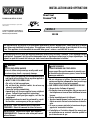
INSTALLATION AND OPERATION
Direct-Vent
Ravenna™ CD
P/N 900124-00 REV. A 01/2015
A French manual is available upon request. Order
P/N 900184-00.
Ce manuel d’installation est disponible en
francais, s implement en faire la demande.
Numéro de la pièce 900184-00.
C
P900124-00
US
Report # 14-192
MODELS
RDV CD
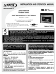
This appliance may be installed in an aftermarket permanently located, manufactured home (USA only) or mobile
home, where not prohibited by local codes. This appliance is only for use with the type of gas indicated on the rating
plate. This appliance is not convertible for use with other gases, unless a certified kit is used.
Cet appareil peut installé dans une maison préfabriquée (mobile) déjà installée à demeure, si les réglements locaux
le permettent. Ce appareil doit être utilisé uniquement avec le type de gaz indiqué sure la plaque signalétique. Cet
appareil ne peut être converti à d'autres gaz, sauf si une trousse de conversion est utilsée.
WARNING:
FIRE OR EXPLOSION HAZARD
Failure to follow safety warnings exactly could result
in serious injury, death, or property damage.
—Do not store or use gasoline or other flammable vapors
and liquids in the vicinity of this or any other appliance.
— WHAT TO DO IF YOU SMELL GAS
• Do not try to light any appliance.
• Do not touch any electrical switch; do not use any
phone in your building.
• Leave the building immediately.
•Immediately call your gas supplier from a neighbor’s
phone. Follow the gas supplier’s instructions.
• If you cannot reach your gas supplier, call the fire
department.
—Installation and service must be performed by a qualified installer, service agency or the gas supplier.
INSTALLER: Leave this manual with the appliance.
CONSUMER: Retain this manual for future reference.
INstallateur: Laissez cette notice avec l'appareil.
Consommateur: Conservez cette notice pour consultation ultérieure.
AVERTISSEMENT:
RISQUED'INDENDIE OU D'EXPLOSION
Le non-respect Des avertissements de sécurité pourrait d'entraîner des blessures graves, la mort ou des
dommages matériels.
—Ne pas entreposer ni utilizer d’essence ni d’autres
vapeurs ou liquides inflammables dans le voisinage
de cet appareil ou de tout autre appareil.
—QUE FAIRE SI VOUS SENTEZ UNE ODEUR DE GAZ:
• Ne pas tenter d’allumer d’appareil.
• Ne touchez à aucan interrupteur. Ne pas vous servir
des téléphones se trouvant dans le bâtiment où vous
trouvez.
• Sortez immédiatement de bâtiment.
• Appelez immédiatement votre fournisseur de gaz
depuis un voisin. Suivez les instructions du fournisseur.
• Si vous ne pouvez rejoindre le fournisseur de gaz,
appelez le service des incindies.
—L’installation et l’entretien doivent être assurés par
un installateur ou un service d’entretien qualifié ou
par le fournisseur de gaz.
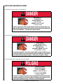
Safety and Your Fireplace Insert
See attached color flyer for proper color representation
DANGER
HOT GLASS WILL
CAUSE BURNS.
DO NOT TOUCH GLASS
UNTIL COOLED.
NEVER ALLOW CHILDREN
TO TOUCH GLASS.
A barrier* designed to reduce the risk of burns from the hot viewing glass is provided with this appliance and shall be installed for the protection of children and
other at-risk individuals. *Included with required facade.
Voir ci-joint tract pour une bonne représentation de la couleur
DANGER
VITRE CHAUDE
RISQUE DE BRÛLURES.
NE TOUCHEZ PAS UNE VITRE
NON REFROIDIE.
NE LAISSEZ JAMAIS UN ENFANT
DE TOUCHER LA VITRE.
L'écran pare-étincelles* fourni avec ce foyer réduit le risque de brûlure en cas
de contact accidentel avec la vitre chaude et doit être installé pour la protection
Des enfants et Des personnes à risques. *incluse avec le façade - Requis.
Vea el volante adjunto para la representación de color adecuado
PELIGRO
2
EL VIDRIO CALIENTE
CAUSARÁ QUEMADURAS.
USTED DEBE NUNCA
TOCAR EL VIDRIO CALIENTE.
LOS NIÑOS DEBEN NUNCA
TOCAR EL VIDRIO.
Una barrera* diseñada para reducir el riesgo de quemaduras desde la mirilla (vidrio)
caliente es proveida con este aparato y deberá instalarse para la protección de los
niños y otros individuos en riesgo. *Incluida con la fachada requerida.
NOTE: DIAGRAMS & ILLUSTRATIONS ARE NOT TO SCALE.
Safety and Your La sécurité et votre Seguridad y su
Fireplace Insert poêle encastrable
chimenea
All parts of your IHP
fireplace insert get
EXTREMELY HOT!
To prevent severe burns
and injuries, do Not
remove the barrier on
the facade (required
accessory) which prevents
direct contact with the glass.
Follow the safety instructions below
and be sure everyone in your household
understands this burn hazard:
• The surfaces on your fireplace get
EXTREMELY HOT!
• The glass on the front of the
fireplace reaches EXTREMELY HIGH
temperatures and can cause severe
burns if touched.
• Keep children away from an operating
fireplace. Closely supervise children
in any room where a fireplace is
operating to prevent contact with glass.
• Keep clothing, furniture, gasoline, and
other flammable liquids away from the
fireplace.
• Even after the gas is turned off,
fireplace surfaces remain extremely
hot.
Be sure to attach the enclosed Safetyin-Operation Warnings where you
turn on your fireplace, to help remind
everyone of the dangers associated with
high temperatures (see pages 6-7).
Read Important Safety Information on
page 5.
[ENGLISH]
Toutes les parties de votre
poêle encastrable IHP
deviennent EXTRÊMEMENT
CHAUDES !
¡Todas las partes de la
chimenea IHP se ponen
MUY CALIENTES!
Afin d'éviter les brûlures
graves ou les blessures,
ne pas retirer l'écran
de protection de la
face avant (accessoire
obligatoire) qui empêche
tout contact direct avec la vitre.
Suivez les instructions de sécurité
ci-dessous et veillez à ce que tous
les membres de votre famille soient
conscients du danger de brûlure
encouru :
Para evitar quemaduras y lesiones
graves, no quite el protector de malla
o guardia de seguridad que evita el
contacto directo con el vidrio.
• Les surfaces de votre foyer deviennent
EXTRÊMEMENT CHAUDES !
• La vitre située à l'avant du foyer atteint
des températures EXTRÊMEMENT
ÉLEVÉES et peut causer de graves
blessures en cas de contact.
• Tenez les enfants à l'écart du foyer
lorsqu'il fonctionne. Surveillez
attentivement les enfants dans les
pièces où un foyer est utilisé afin
d'éviter qu'ils ne soient en contact avec
la vitre.
• Tenez tous les vêtements, les meubles,
l'essence et tout autre liquide
inflammable à l'écart du foyer.
• Même après fermeture du gaz, les
surfaces du foyer restent extrêmement
chaudes.
Veillez à coller les Étiquettes de mise
en garde relatives à la sécurité
d'utilisation à l'endroit où vous
utilisez le foyer, pour rappeler à tous
les utilisateurs les dangers liés aux
températures élevées (voir pages 6-7).
Lisez la section Informations
importantes relatives à la sécurité,
page 5.
[FRENCH]
Siga las instrucciones de seguridad
a continuación y asegúrese de que
todos en su hogar sepan acerca de este
peligro de quemadura:
• ¡Las superficies de la chimenea se
ponen MUY CALIENTES!
• El vidrio delante de la
chimenea alcanza temperaturas
EXTREMADAMENTE ALTAS y puede
causar quemaduras graves si se toca.
• Mantenga a los niños alejados de
la chimenea en funcionamiento.
Supervise en forma cercana a los niños
en cualquier cuarto donde haya una
chimenea funcionando para impedir el
contacto con el vidrio.
• Mantenga la ropa, mobiliario, gasolina
y otros líquidos inflamables alejados
de la chimenea.
• Aún después de haber apagado el
gas, las superficies de la chimenea
permanecen extremadamente
calientes.
Asegúrese de colocar las Etiquetas de
advertencia de seguridad de operación
en el lugar donde enciende la chimenea,
para que todos recuerden los peligros
asociados con las altas temperaturas
(ver la páginas 6-7).
Lea la Información importante de
seguridad en la página 5.
[SPANISH]
3
CONGRATULATIONS!
When you purchased your new gas fireplace insert, you joined
the ranks of thousands of individuals whose answer to their home
heating needs reflects their concern for aesthetics, efficiency and
our environment. We extend our continued support to help you
achieve the maximum benefit and enjoyment available from your
new gas fireplace insert.
Thank you for selecting an Innovative Hearth Products LLC (IHP)
gas fireplace insert as the answer to your home heating needs.
TABLE OF CONTENTS
Installation............................................................... 15-21
Venting Installation............................................... 15
Vertical Venting................................................... 16
Zero Clearance Fireplace Installation......................... 17
Glass Door..................................................... 17-18
Firebox Liner Kit Installation (required accessory).......... 18
Glass Media Installation (required accessory)............... 19
Surround Panels Installation (required accessory).......... 19
Facade Installation (required accessory)..................... 16
Gas Line Installation............................................. 20
Gas Pressure Requirements..................................... 20
LP and Natural Gas Supplies.................................... 20
Safety and Your Fireplace Insert........................................ 2-3
Air Shutter Adjustment........................................... 21
Using this Manual........................................................... 4
Battery Backup - Battery Installation........................... 21
Important Safety Information.............................................. 5
Installer - Attaching Safety In Operation Warnings......... 21
Homeowner - Attaching Safety In Operation Warnings................ 6
Operation................................................................ 22-25
Installer - Attaching Safety In Operation Warnings.................... 7
Pre-Lighting Checklist............................................ 22
Appliance Installation, Service, and Maintenance Notices........... 8
Operating Instructions............................................ 22
Appliance Operation Notices............................................... 8
Intermittent/Standing Pilot Mode............................... 22
Warranty Information....................................................... 8
Operation ...................................................... 23-25
Important Safety And Warning Information.............................. 9
Flame Color and Behavior....................................... 25
Orifice Size / Altitude Adjustment........................................ 10
Paint Curing........................................................ 25
Smoke Detectors............................................................ 10
Quiet Operation.................................................... 25
The Fireplace Insert........................................................ 10
Wiring Diagrams............................................................ 26
Fireplace Requirements................................................... 10
Maintenance and Servicing........................................... 27-28
Codes and Approvals....................................................... 11
Maintenance Checklist........................................... 27
Requirements For The Commonwealth of Massachusetts............ 11
Glass Maintenance............................................... 28
New York City, New York (MEA).......................................... 11
Fuel Conversion................................................... 28
Pre-Installation......................................................... 12-15
Blower Removal................................................... 28
Features............................................................ 12
Electrical Requirements......................................... 28
Replacing A Damaged Barrier.................................. 29
Packaging List..................................................... 12
Ratings............................................................. 12
Troubleshooting............................................................. 30
Insert and Fireplace Dimensions............................... 13
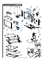
Replacement Parts..................................................... 31-32
Clearances to Combustibles..................................... 14
Accessories.............................................................. 33-34
Insert Leveling..................................................... 14
Insert Labels............................................................. 35-36
Fan Control Module Switch....................................... 15
Warranty..................................................................... 37
Product Reference Information........................................... 38
USING THIS MANUAL
Please read and carefully follow all of the instructions found in this
manual. Please pay special attention to the safety instructions provided
in this manual.
PRODUCT IS SUBJECT TO CHANGE WITHOUT NOTICE
4
IMPORTANT SAFETY Information
Important Safety Information
L’information de sûreté
importante
1. WARNING: Do not operate appliance
with the glass front removed, cracked
or broken.
1. AVERTISSEMENT. Ne pas utiliser l’appareil 1. ADVERTENCIA: No opere el artefacto con el
si le panneau frontal en verre n’est pas en
frente de vidrio quitado, agrietado o roto.
place, est craqué ou brisé.
2. No use este artefacto si alguna de sus partes
2. Ne pas se servir de cet appareil s’il a été
ha estado bajo agua. Llame de inmediato
plongé dans l’eau, même partiellement.
a un técnico de servicio calificado para
Faire inspecter l'appareil par un technicien
que inspeccione el artefacto y reemplace
qualifié et remplacer toute partie du systéme
cualquier parte del sistema de control y
de contrôle et toute commande qui ont été
cualquier control de gas que haya estado
plongées dans l'eau.
bajo agua.
3. En raison des températures élevées,
2. Do not use this appliance if any part
has been under water. Immediately
call a qualified service technician to
inspect the appliance and to replace
any part of the control system and
any gas control which has been under
water.
3. Due to high temperatures, the appliance should be located out of traffic
and away from furniture and draperies.
4. Children and adults should be alerted
to the hazards of high surface temperature and should stay away to avoid
burns or clothing ignition.
5. Clothing or other flammable material
should not be placed on or near the
appliance.
6. Young children should be carefully
supervised when they are in the same
room as the appliance. Toddlers,
young children, and others may be susceptible to accidental contact burns.
A physical barrier is recommended
if there are at-risk individuals in the
house. To restrict access to a fireplace
or stove, install an adjustable safety
gate to keep toddlers, young children,
and other at-risk individuals out of the
room and away from hot surfaces.
7. Any safety screen, guard or barrier
removed for servicing an appliance
must be replaced prior to operating
the appliance.
8. Installation and repair should be done
by a qualified service person. The
appliance should be inspected before
use and at least annually by a professional service person. More frequent
cleaning may be required due to
excessive lint from carpeting, bedding
material, et cetera. It is imperative
that control compartments, burners,
and circulating air passageways of the
appliance be kept clean. See maintenance instructions on Pages 27-29.
l’appareil devrait être installé dans un
endroit où il y a peu de circulation et loin
du mobilier et des tentures.
4. Les enfants et les adultes devraient être
informés des dangers que posent les températures de surface élevées et se tenir à
distance afin d’éviter des brûlures ou que
leurs vêtements ne s’enflamment.
5. On ne devrait pas placer de vêtements
ni d’autres matières inflammables sur
l’appareil ni à proximité.
6. Les jeunes enfants devraient être surveillés
étroitement lorsqu’ils se trouvent dans la
même pièce que l’appareil. Les tout petits,
les jeunes enfants ou les adultes peuvent
subir des brûlures s’ils viennent en contact
avec la surface chaude. Il est recommandé
d’installer une barrière physique si des
personnes à risques habitent la maison.
Pour empêcher l’accès à un foyer ou à un
poêle, installez une barrière de sécurité
; cette mesure empêchera les tout petits,
les jeunes enfants et toute autre personne
à risque d’avoir accès à la pièce et aux
surfaces chaudes.
7. Tout écran ou protecteur retiré pour permettre l’entretien de l’appareil doit être
remis en place avant de mettre l’appareil
en marche.
8. L’installation et la réparation devrait être
confiées à un technicien qualifié. L’appareil
devrait faire l’objet d’une inspection par un
technicien professionnel avant d’être utilisé
et au moins une fois l’an par la suite. Des
nettoyages plus fréquents peuvent être
nécessaires si les tapis, la literie, et cetera
produisent une quantité importante de poussière. Il est essentiel que les compartiments
abritant les commandes, les brûleurs et les
conduits de circulation d’air de l’appareil
soient tenus propres. Voyez les instructions
d’entretien à la Pages 27-29.
NOTE: DIAGRAMS & ILLUSTRATIONS ARE NOT TO SCALE.
Información importante de
seguridad
3. Debido a las altas temperaturas, el artefacto
debe situarse fuera de las áreas de tráfico y
lejos del mobiliario y cortinas.
4. Se debe alertar a los niños y adultos sobre
los peligros de las altas temperaturas en la
superficie y que se mantengan alejados para
evitar quemaduras o ignición de la ropa.
5. No debe colocarse ropa u otros materiales
inflamables sobre y cerca del artefacto.
6. Se debe supervisar de cerca a los niños
cuando estén en el mismo cuarto que el
artefacto. Los niños pequeños, los jóvenes
y otras personas pueden ser susceptibles
a quemaduras por contacto accidental. Se
recomienda instalar una barrera física si hay
personas en riesgo en la casa. Para restringir
el acceso a una chimenea o estufa, instale
una puerta de seguridad ajustable para
mantener a los niños pequeños, jóvenes y
otras personas en riesgo fuera del cuarto y
lejos de las superficies calientes.
7. Cualquier malla o resguardo de seguridad
quitado para dar servicio a un artefacto, debe
reinstalarse antes de operar el artefacto.
8. Una persona de servicio competente debe
realizar la instalación y reparación. Una
persona de servicio profesional debe
inspeccionar el artefacto antes de usar al
menos una vez por año. Se puede requerir
limpieza más frecuente debido a la pelusa
excesiva del alfombrado, del material de
cobijas, etc. Es imprescindible mantener
limpios los compartimientos de control, los
quemadores y los pasajes de circulación del
aire del artefacto. Ver las instrucciones de
mantenimiento en la páginas 27-29.
5
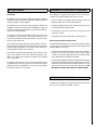
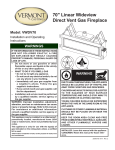
HOMEOWNER’S INSTRUCTIONS - ATTACHING SAFETY IN OPERATION WARNINGS
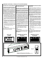
Attaching Safety in Operation Warnings
Your appliance has been furnished with safety instruction labels that are to be affixed to the operation and
control points of the appliance. A safety instruction
label should be affixed next to the burner control
switch where the appliance is turned on and off (See
Figure A) and the remote control handheld transmitter
(See Figure B). The warnings should already have
been put in place when the appliance initial set-up
was completed. If they are not affixed at these spots,
locate the multi-lingual adhesive labels provided with
these instructions and proceed as follows:
1. Locate the control switch on the control panel
of your appliance (verify the switch operates the
appliance by turning it on and off). Clean the
surface on the control panel thoroughly to remove
any dust and oils. Affix the label next to the burner
control switch that controls the appliance (Figure
A). Choose the language primarily spoken in the
home.
2. Locate the remote control transmitter and clean
it thoroughly to remove any dust and oils. Affix
the label to the surface of handheld transmitter
(Figure B). Choose the language primarily spoken
in the home.
3. If you are unable to locate the labels, please
contact IHP or your nearest IHP dealer to receive
additional safety instruction labels free of charge.
Cat. No. H8024 Replacement Label Kit
IHP
IronStrike.us.com
Note: English is red text on clear label. French and
Spanish are white text on black label.
Apposition des mises en garde relatives
à la sécurité d’utilisation
Colocación de advertencias de seguridad
en operación
Votre appareil a été livré avec des étiquettes de sécurité
qui doivent être collées à côté des dispositifs de contrôle
du brûleur. Une étiquette de sécurité devrait être collée sur
la plaque du récepteur contrôlant l’allumage de l’appareil
(voir Figure A) et sur le boîtier de la télécommande
(Figure B). Les mises en garde auraient dû être collées au
moment de l’installation initiale de l’appareil. Si ce n’est
pas le cas, prenez les étiquettes adhésives multilingues
fournies avec ces instructions et procédez comme suit :
1. Repérez le contrôleur sur le panneau de contrôle de
votre appareil (vérifiez que l’interrupteur contrôle
le fonctionnement de l’appareil en le faisant
basculer de Marche à Arrêt, et vice-versa). Nettoyez
soigneusement la surface sur le panneau de contrôle
pour éliminer la poussière et les traces de graisse
ou d’huile. Collez l’étiquette à côté du bouton de
contrôle du brûleur qui contrôle l’appareil (Figure
A). Choisissez la langue qui est principalement parlée
dans la résidence du propriétaire.
2. Repérez la télécommande et nettoyez-la soigneuse
ment pour éliminer la poussière et les traces de
graisse ou d’huile. Collez l’étiquette sur le boîtier de
la télécommande (Figure B). Choisissez la langue
qui est principalement parlée dans la résidence du
propriétaire.
3. Si vous ne parvenez pas à localiser les étiquettes, s’il
vous plaît contactez IHP ou votre revendeur le plus
proche pour recevoir IHP étiquettes d’instructions
de sécurité supplémentaires gratuitement.
Étiquettes de remplacement, n° cat. H8024
Su artefacto incluye etiquetas de instrucciones de
seguridad que deben colocarse en los puntos de
operación y control del artefacto. Se debe colocar una
etiqueta de instrucciones de seguridad adyacente al
interruptor de control del quemador donde se enciende y
se apaga el artefacto (ver la Figura A) y en el transmisor
de control remoto (Figura B). Las advertencias ya deben
haberse colocado cuando se completó la instalación
inicial del artefacto. Si no están colocadas en estos
lugares, encuentre las etiquetas adhesivas multilingües
proporcionadas con estas instrucciones y prosiga de
la siguiente manera:
1. Identifique el interruptor de control en el panel de
control del artefacto (verifique que el interruptor
opera el artefacto encendiéndolo y apagándolo).
Limpie bien la superficie del panel de control para
quitar el polvo y aceite. Pegue la etiqueta adyacente
al interruptor de control del quemador que controla
el artefacto (Figura A). Seleccione el idioma que más
se habla en la casa.
2.Identifique el transmisor de control remoto y
límpielo bien para quitar el polvo y aceite. Pegue la
etiqueta en la superficie del transmisor (Figura B).
Seleccione el idioma que más se habla en la casa.
3. Si no puede encontrar las etiquetas, sírvase llamar
a Innovative Hearth Products o al distribuidor
de Innovative Hearth Products más cercano para
recibir etiquetas de instrucciones de seguridad
adicionales gratuitas.
IHP
IronStrike.us.com
Remarque : Le texte anglais est rouge sur un support
transparent. Le texte français et espagnol est blanc
sur un support noir.
SAFETY LABEL
DIAGRAMS
DIAGRAMMES DES ÉTIQUETTES
DE SÉCURITÉ
ON
Figure A
Juego de etiquetas de repuesto - Nº de cat. H8024
IHP
IronStrike.us.com
Nota: La etiqueta en inglés es transparente con texto
rojo. Las etiquetas en francés y español son negras
con texto blanco.
DIAGRAMAS DE ETIQUETAS
DE SEGURIDAD
BURNER
TOTAL
RT
COMFO L
CONTRO
Figure B
AUTO
PILOT
Illustrations are for example only. Your accessories may be different.
Les illustrations sont par exemple uniquement. Vos accessoires peuvent être différents.
Las ilustraciones son sólo ejemplos. Tu accesorios pueden ser diferentes.
6
NOTE: DIAGRAMS & ILLUSTRATIONS ARE NOT TO SCALE.
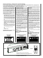
INSTALLER INSTRUCTIONS - ATTACHING SAFETY IN OPERATION WARNINGS
It is the installers responsibility to ensure these warnings are properly affixed during installation. These warning labels are a
critical step in informing consumers of safe operation of this appliance.
Attaching Safety in Operation Warnings
It is required that the set of safety instruction labels
that have been furnished with the appliance be affixed
to the operation and control points of the appliance. A
safety instruction label should be affixed next to the
burner control switch where the appliance is turned
on and off (See Figure A) and the remote control
handheld transmitter (See Figure B). To properly
complete the installation of this appliance, locate the
multi-lingual adhesive labels provided with these
instructions and proceed as follows:
1. Locate the control switch on the control panel
of your appliance (verify the switch operates the
appliance by turning it on and off). Clean the
surface on the control panel thoroughly to remove
any dust and oils. Affix the label next to the burner
control switch that controls the appliance (Figure
A). Choose the language primarily spoken in the
home. If unknown, affix the English language
label.
2. Locate the remote control transmitter and clean
it thoroughly to remove any dust and oils. Affix
the label to the surface of handheld transmitter
(Figure B). Choose the language primarily
spoken in the home. If unknown, affix the English
language label.
3. If you are unable to locate the labels, please
contact IHP or your nearest IHP dealer to receive
additional safety instruction labels free of charge.
Cat. No. H8024 Replacement Label Kit
IHP
IronStrike.us.com
Note: English is red text on clear label. French and
Spanish are white text on black label.
SAFETY LABEL
DIAGRAMS
Apposition des mises en garde relatives
à la sécurité d’utilisation
Il est impératif que le jeu d’étiquettes de sécurité qui
ont été fournies avec le foyer soient collées à côté des
dispositifs de contrôle du impératif. Une étiquette de
sécurité devrait être collée sur la plaque du récepteur
contrôlant l’allumage de l’appareil (voir Figure A) et sur
le boîtier de la télécommande (Figure B). Les mises en
garde auraient dû être collées au moment de l’installation
initiale de l’appareil. Si ce n’est pas le cas, prenez les
étiquettes adhésives multilingues fournies avec ces
instructions et procédez comme suit :
1. Repérez le contrôleur sur le panneau de contrôle de
votre appareil (vérifiez que l’interrupteur contrôle
le fonctionnement de l’appareil en le faisant
basculer de Marche à Arrêt, et vice-versa). Nettoyez
soigneusement la surface sur le panneau de contrôle
pour éliminer la poussière et les traces de graisse
ou d’huile. Collez l’étiquette à côté du bouton de
contrôle du brûleur qui contrôle l’appareil (Figure
A). Choisissez la langue qui est principalement parlée
dans la résidence du propriétaire. En cas de doute,
collez l’étiquette en anglais.
2. Repérez la télécommande et nettoyez-la soigneuse
ment pour éliminer la poussière et les traces
de graisse ou d’huile. Collez l’étiquette sur le boîtier
de la télécommande (Figure B). Choisissez la
langue qui est principalement parlée dans la
résidence du propriétaire. En cas de doute, collez
l’étiquette en anglais.
3. Si vous ne parvenez pas à localiser les étiquettes, s’il
vous plaît contactez IHP ou votre revendeur le plus
proche pour recevoir IHP étiquettes d’instructions
de sécurité supplémentaires gratuitement.
Étiquettes de remplacement, n° cat. H8024
IHP
IronStrike.us.com
Remarque : Le texte anglais est rouge sur un support
transparent. Le texte français et espagnol est blanc
sur un support noir.
DIAGRAMMES DES ÉTIQUETTES
DE SÉCURITÉ
ON
Figure A
Colocación de advertencias de seguridad
en operación
Se requiere que el juego de etiquetas de instrucciones
de seguridad que se incluyeron con la artefacto se
coloque en los puntos de operación y control de la
misma. Se debe colocar una etiqueta de instrucciones
de seguridad adyacente al interruptor de control del
quemador donde se enciende y se apaga el artefacto
(ver la Figura A) y en el transmisor de control remoto
(Figura B). Las advertencias ya deben haberse colocado
cuando se completó la instalación inicial del artefacto.
Si no están colocadas en estos lugares, encuentre las
etiquetas adhesivas multilingües proporcionadas con
estas instrucciones y prosiga de la siguiente manera:
1. Identifique el interruptor de control en el panel de
control del artefacto (verifique que el interruptor
opera el artefacto encendiéndolo y apagándolo).
Limpie bien la superficie del panel de control para
quitar el polvo y aceite. Pegue la etiqueta adyacente
al interruptor de control del quemador que controla
el artefacto (Figura A). Seleccione el idioma que
más se habla en la casa. Si no sabe cuál es, use la
etiqueta en inglés.
2. Identifique el transmisor de control remoto y límpielo
bien para quitar el polvo y aceite. Pegue la etiqueta
en la superficie del transmisor (Figura B). Seleccione
el idioma que más se habla en la casa. Si no sabe
cuál es, use la etiqueta en inglés.
3. Si no puede encontrar las etiquetas, sírvase llamar
a Innovative Hearth Products o al distribuidor de
Innovative Hearth Products más cercano para
recibir etiquetas de instrucciones de seguridad
adicionales gratuitas.
Juego de etiquetas de repuesto - Nº de cat. H8024
IHP
IronStrike.us.com
Nota: La etiqueta en inglés es transparente con texto
rojo. Las etiquetas en francés y español son negras
con texto blanco.
DIAGRAMAS DE ETIQUETAS
DE SEGURIDAD
BURNER
TOTAL
RT
COMFO L
CONTRO
Figure B
AUTO
PILOT
Illustrations are for example only. Your accessories may be different.
Les illustrations sont par exemple uniquement. Vos accessoires peuvent être différents.
Las ilustraciones son sólo ejemplos. Tu accesorios pueden ser diferentes.
7
NOTE: DIAGRAMS & ILLUSTRATIONS ARE NOT TO SCALE.
Appliance Installation, Service, and
Maintenance Notices
WARNING: Improper installation, adjustment, alteration,
service or maintenance can cause injury or property damage.
Refer to the owner’s information manual provided with this
appliance. For assistance or additional information consult a
qualified installer, service agency or the gas supplier.
AVERTISSEMENT : Une installation, un réglage, une
modification, une réparation ou un entretien mal effectué
peut causer des dommages matériels ou des blessures.
Voir la notice de l’utilisateur qui accompgne l’appareil.
Pour de l’aide ou des renseignements supplémentaires,
consultez un installateur, un technicien agréé ou le
fournisseur de gaz.
Only trim kit(s) supplied by the manufacturer shall be used
in the installation of this appliance.
Seules les trousses de garniture fournies par le fabricant
doivent être utilisées pour l’installation de cet appareil.
If the barrier becomes damaged, the barrier shall be
replaced with the manufacturer’s barrier for this appliance.
Si l'écran est endommagé, il doit être remplacé par
celui fournit par le fabricant de cet appareil.
Reinstall any barrier removed before operating the
appliance. The barrier is designed to reduce the risk of
burns from hot glass. Do not operate the appliance without
the barrier installed.
Appliance Operation Notices
These fireplace inserts are vented gas appliances. Do not
burn wood or other material in these appliances.
These appliances are designed to operate on natural gas or
propane gas only. The use of other fuels or combinations of
fuels will degrade the performance of this system and may
be dangerous.
These appliances must not be connected to a chimney or flue
serving a separate solid fuel burning appliance.
Provide adequate clearances around air openings and
adequate accessibility clearance for service and proper operation. Never obstruct the front openings of the appliance.
Any change to this appliance and/or its operating controls is
dangerous. Improper installation or use of this appliance can
cause serious injury or death from fire, burns, explosion or
carbon monoxide poisoning.
These appliances are designed as supplemental heaters.
Therefore, it is advisable to have an alternate primary heat
source when installed in a dwelling.
CARBON MONOXIDE POISONING: Early signs of carbon
monoxide poisoning are similar to the flu with headaches,
dizziness and/or nausea. If you have these signs, obtain fresh
air immediately. Turn off the gas supply to the appliance and
have it serviced by a qualified professional, as it may not be
operating correctly. Some people are more affected by carbon
monoxide than others, including pregnant women, people with
heart or lung disease or anemia, those under the influence of
alcohol, and those at high altitudes.
Turn off gas and electrical power to the appliance and allow
it to cool before cleaning or servicing the appliance.
Warranty Information
Your gas appliance is covered by a limited 20-year warranty.
You will find a copy of the warranty accompanying this manual.
Please read the warranty to be familiar with its coverage.
Retain this manual. File it with your other documents for future
reference.
Failure to comply with the installation and operating
instructions provided will result in an improperly installed
and operating appliance, voiding its warranty.
Do not attempt to alter or modify the construction of the
appliance or its components. Any modification or alteration
may void the warranty, certification, and listings of this unit.
8
NOTE: DIAGRAMS & ILLUSTRATIONS ARE NOT TO SCALE.
IMPORTANT SAFETY AND WARNING
INFORMATION
INSTALLER: THESE INSTRUCTIONS ARE TO REMAIN WITH THE
HOME OWNER!
FOR YOUR SAFETY do not install or operate this appliance without
first reading and understanding this manual. Any installation or
operation of the appliance deviating from that which is stated
in this manual WILL void the warranty and may be hazardous.
IHP, its employees, or any of its representatives assume no
responsibility for any damages caused by an inoperable, inadequate, or unsafe condition as a result of any improper operation,
service or installation procedures, whether direct or indirect.
DO NOT ATTEMPT TO SERVICE THE APPLIANCE YOURSELF.
Do not make any make-shift compromises during installation.
Any modification or alteration may result in damage to the appliance or dwelling and will void the warranty, certification and
listings of this unit.
Failure to use manufacturer provided parts, variations in techniques and construction materials or practices other than those
described in this manual may create a fire hazard and void the
limited warranty.
This gas appliance must be equipped for the proper fuel type
and altitude at which it will be operated. Any operation outside
the parameters outlined in this manual may result in a hazardous condition and will void the warranty. Please carefully read
the sections pertaining to these subjects and/or be sure your
appliance is properly equipped.
Never use solid fuels such as wood, paper, cardboard, coal, or
any flammable liquids, etc., in this appliance.
Plated surfaces must be cleaned with glass cleaner and a clean
soft cloth before firing the first time or fingerprints will remain
permanently. NEVER use brass polish to clean plated surfaces,
this will remove the plating!!!
CAUTION: Hot while in operation. Do not touch. Severe Burns
may result. Keep children, clothing furniture, gasoline and other
liquids having flammable vapors away.
ATTENTION: L’appareil est chaud lorsqu’il fonctionne. Ne
pas toucher l’appareil. Risque de brûlures graves. Surveiller
les enfants. Garder les vêtements, les meubles, l’essence
ou autres liquides produisant des vapeur inflammables loin
de l’appareil.
Clearances are in accordance with local installation codes and
the requirements of the gas supplier.
Les dégagements sont conformes aux codes d'installation
locaux et aux exigences du foumisseur de gaz.
This appliance is only for use with the type of gas indicated on
rating plate. This appliance is not convertible for use with other
gases, unless a certified kit is used.
Cet appareil doit être utilisé uniquement avec les types de
gaz indiqués sur la plaque signalétique. Ne pas l'utiliser
avec d'autres gaz sauf si un kit de conversion certifié est
installé.
WARNING
Improper installation or use of this appliance can
cause serious injury or death from fire, burns,
explosion or carbon monoxide poisoning.
WARNING
Failure to comply with these installation instructions
will result in an improperly installed and operating
appliance, voiding its warranty.
9
NOTE: DIAGRAMS & ILLUSTRATIONS ARE NOT TO SCALE.
ORIFICE SIZE/ALTITUDE ADJUSTMENT
For altitudes above 2,000 feet (In Canada 4,500 FT/1370 M), the orifice
should be de-rated by 4% for every 1,000 feet to maintain the proper ratio
of gas to air. Improper orifice sizing may result in damage and unsafe
conditions. Changing the orifice should only be done by a qualified service
technician. Contact your IHP dealer for proper orifice sizes.
In Canada - CAN/CGA-2.17-M91 (R2009) (high altitude):
THE CONVERSION SHALL BE CARRIED OUT BY A MANUFACTURER’S
AUTHORIZED REPRESENTATIVE, IN ACCORDANCE WITH THE REQUIREMENTS OF THE MANUFACTURER, PROVINCIAL OR TERRITORIAL
AUTHORITIES HAVING JURISDICTION AND IN ACCORDANCE WITH
THE REQUIREMENTS OF THE CAN/CGA-B149.1 OR CAN/CGA-B149.2
INSTALLATION CODES.
SMOKE DETECTORS
Since there are always several potential sources of fire in any home, we
recommend installing smoke detectors. If possible, install the smoke
detector in a hallway adjacent to the room (to reduce the possibility of
occasional false activation from the heat produced by the appliance). If
your local code requires a smoke detector be installed within the same
room, you must follow the requirements of your local code. Check with
your local building department for requirements in your area.
THE FIREPLACE INSERT
• Must conform with all local, state and national installation codes. In
the absence of local codes, the installation must conform with National
Fuel Gas Code ANSI Z223.1 - latest edition, also known as NFPA 54
(In Canada, the current CAN/CGA B149.1 installation code). Refer to
the National Fuel Gas Code and local zoning and code authorities for
details on installation requirements.
• Manufactured home installations (USA only) must conform with the
Manufactured Home Construction and Safety Standard, Title 24 CFR,
Part 3280, or, when such a standard is not applicable, the Standard for
Manufactured Home Installations, ANSI/NCSBCS A225.1, or Standard
for Gas Equipped Recreational Vehicles and Mobile Housing, CSA
Z240.4.
• Must be vented directly to the outside in accordance with the latest
edition of the National Fuel Gas Code and must never be attached to
a chimney serving a separate solid fuel burning appliance.
• Has been certified for use with either natural gas or propane.
• Is NOT for use with solid fuels.
• Is approved for sitting rooms and/or bedrooms.
• This appliance is suitable for installation into masonry or factory built
fireplaces.
Fireplace Requirements
These heaters are designed to be installed into an existing masonry
fireplace (built to UBC 37 or ULC S628 standards) or factory built solid
fuel, wood burning fireplace (listed to UL 127 or ULC S610) only. All
exhaust gases must be vented outside the structure. Combustion air
is drawn from outside the structure. When installing in a factory built
fireplace, the fireplace grate must be removed and the damper must be
removed or secured open.
10
IMPORTANT: When installing these appliances into a factory
built fireplace or heat-form, the air flow within and around the
fireplace shall not be altered by the installation of the insert
(i.e. DO NOT BLOCK louvers or cooling air inlet or outlet ports,
circulating air chambers in a steel fireplace liner or metal heat
circulator).
CAUTION
• Trim panels or surrounds must not seal ventilation openings in the existing fireplace that the
appliance is installed in.
• The fireplace in which this gas insert is to be
installed must be thoroughly cleaned if it has
been used to burn wood or synthetic logs. Have
the chimney and all inside surfaces of the fireplace brushed and vacuumed so that no soot,
embers, or loose combustion deposits can be
drawn into the heat circulation blower and blown
into the living area.
• If any portion of the chimney system shows signs
of structural or mechanical weaknesses, such
as: cracks, leaky joints, corroded or warped
surfaces, the faulty portion must be repaired
or replaced prior to installing this appliance.
• The factory built firebox must accept the insert
without modification other than removing bolted
or screwed together pieces such as baffles /
smoke shelf / deflectors, ash lips, glass door,
screen or door tracks, log grates, refractory or
masonry lining and damper assemblies. Any
fireplace component, which is removed, must be
retained so they can be reinstalled to restore the
fireplace to its original operating condition. The
removal of any part must not alter the integrity
of the outer shell of the pre-engineered fireplace
cabinet in any way. Any parts removed must be
replaceable. If any components are removed
from (or altered) from the existing fireplace, a
Warning Label (see Figure 1) must be affixed
inside the fireplace firebox, so that it shall be
visible upon removal of the fireplace insert. Note:
RTV high temperature silicone is an approved
adhesive to affix the label.
WARNING
THIS FIREPLACE HAS BEEN ALTERED TO
ACCOMMODATE A FIREPLACE INSERT AND
SHOULD BE INSPECTED BY A QUALIFIED
PERSON PRIOR TO RE-USE AS A
CONVENTIONAL FIREPLACE.
Figure 1 - Fireplace Warning Label
CODES AND APPROVALS
Certification
Gas appliances must be tested and certified by a nationally recognized
testing and certification laboratory to ANSI (American National Standard
Institute) gas appliance safety standards.
This appliance has been tested and certified to ANSI Z21.88/CSA 2.33
Standard for Vented Gas Fireplace Heater and CAN/CGA 2.17-M91 and
UL 307B Gas Burning Heating Appliances for Manufactured (Mobile)
Homes in both USA and Canada.
This appliance has met all necessary ANSI Standards and is fully certified
for installation in any community. If there are any questions or if you
need further substantiation contact your IHP dealer. If you have further
questions, please contact IHP.
Check all local building and safety codes before installation. The installation instructions and appropriate code requirements must be followed
exactly and without compromise. In the absence of local codes the following standards and codes must be followed.
The Installation must conform with local codes or, in the absence of local
codes, with the National Fuel Gas Code, ANSI Z223.1/NFPA 54- latest
edition, or the Natural Gas and Propane Installation Code, CAN/CGA
B149.1- latest edition.
The appliance, when installed, must be electrically grounded and wired
in accordance with local codes or, in the absence of local codes, with the
National Electrical Code, ANSI/NFPA 70 - latest edition, or the Canadian
Electrical Code, CSA C22.1 - latest edition.
COMMONWEALTH OF MASSACHUSETTS REQUIREMENTS
These appliances are approved for installation in the US state of Massachusetts if the following additional requirements are met:
• Install this appliance in accordance with Massachusetts Rules and
Regulations 248 C.M.R. Sections 4.00 through 8.00.
• Installation and repair must be done by a plumber or gas fitter licensed
in the Commonwealth of Massachusetts.
• The flexible gas line connector used shall not exceed 36 inches (92
centimeters) in length.
• The individual manual shut-off must be a T-handle type valve.
Massachusetts Horizontal Vent Requirements
In the Commonwealth of Massachusetts, horizontal terminations installed
less than seven (7) feet above the finished grade must comply with the
following additional requirements:
• A hard wired carbon monoxide detector with an alarm and battery
back-up must be installed on the floor level where the gas fireplace
is installed. The carbon monoxide detector must comply with NFPA
720, be ANSI/UL 2034 listed and be ISA certified.
• A metal or plastic identification plate must be permanently mounted to
the exterior of the building at a minimum height of eight (8) feet above
grade and be directly in line with the horizontal termination. The sign
must read, in print size no less than one-half (1/2) inch in size, GAS
VENT DIRECTLY BELOW. KEEP CLEAR OF ALL OBSTRUCTIONS.
NEW YORK CITY, NEW YORK (MEA)
Installation of these appliances are approved for installation in New York
City in the US state of New York (MEA#: 138-07-E).
11
Packaging List
PRE-INSTALLATION
Insert Body Packaging List
Features
Installation Options
Manufactured (Mobile) Home
Natural Gas Or Propane (LP)
Bedrooms
Electrical
The standard blower motor requires 120 Volts AC for operation. The
fireplace is not dependent on the blower to operate. WARNING - Electrical
Grounding Instructions - This appliance is equipped with a three-prong
(grounding) plug for your protection against shock hazard and should
be plugged directly into a properly grounded three-prong receptacle.
Do not cut or remove the grounding prong from this plug.
1
1
1
1
1
1
Insert Body
Power Cord
Fasteners: 6 slotted 1/4" truss screws
6 speed nuts
9 spring clips
3 plastic adhesive wire restraints
Installation and Operation Manual
Remote Control
Glass Media Measuring Box
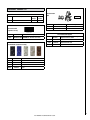
Black Porcelain Panel Set - One Required
Decorative Facade Kits - One Required
Contemporary Facade
Cast pillar Facade
Electronic Valve
This appliance is equipped with an electronic valve and electronic pilot
ignition system (which can be switched from Intermittent to standing
pilot mode - see Page 22). External electrical 120 Volt power is required
to operate the blower system of this appliance and recommended to operate the burner system. This appliance is equipped with a battery backup
system in case of a power outage (see Battery Backup on Page 21 for
more information).
Fuel
THIS APPLIANCE IS EQUIPPED FOR NATURAL GAS.
Surround Kits - One Required
Traditional 1-pc. (41"W x 29"H)
Traditional 3-pc. (41"W x 29"H, 48"W x 29"H, 41"W x
33"H or 48"W x 33"H)
Cast Iron (45-1/2"W x 30"H-Cast Pillar Facade only) *
* See detailed dimensions on Page 34.
Surround Kit Contents
1
2
3
2
This appliance is equipped with an orifice sized for operation with natural
gas.
For conversion to LP/propane gas, see instructions provided with the
appliance.
Orifices and instructions necessary for LP/propane conversion are provided in the gas conversion kit (see Page 33 for ordering information).
Top Surround
Side Surrounds
Black Extruded Trim Pieces
Elbowed Trim Fasteners
Media Kits - One Required
This appliance comes from the factory equipped to burn natural gas at
a specified elevation. Only IHP conversion kits can be used to convert
from NG to LP or LP to NG. Contact your IHP dealer for details.
Reflective Black Glass Media
Reflective Blue Glass Media
Platinum Glass Media
Goldfinger Glass Media
Copper Glass Media
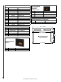
RATINGS
RAVENNA CD (RDV CD)
NATURAL GAS
LP GAS
Max/Min Input BTUh 0-2,000 Feet (0-610 M)u
32,000/21,000
27,000/21,000
Manifold Pressure (IN. WC)
Min. Inlet Pressure (IN. WC)
Maximum heat output BTUs/hour-steady state
(depending on vent configuration)v
P4 Efficiency v
3.5
5.0
10.0
10.5
83% to 86%
83% to 86%
69%
67%
#36
#53
Orifice (DMS) 0-2,000 Feet (0-610 M)u
uUnit factory equipped for 0-2000 FT/0-610 M, In Canada 0-4500 FT/0-1370 M
vTested to CSA P.4.1-09 “Testing Method for Measuring Annual Fireplace Efficiency.
Electrical Rating: 120 VAC, 60 HZ, Less Than 2 Amps
Based on CSA P.4.1-09
12
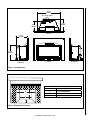
31-1/4"
31-1/8
(794mm)
O.D. = 2-15/16" (75mm)
15-7/8"
15-7/8
(403mm)
13-3/8"
(340mm)
13-3/8
Top View
15-7/8"
15-7/8
(403mm)
19-3/8"
19-3/8
(492mm)
Right Side View
Front View
Left Side View
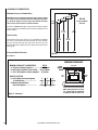
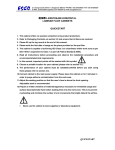
Figure 2 - Insert Dimensions
Minimum Fireplace Opening
A
B
C
A
31-1/2" (800mm) Front Opening Width
B
19-1/2” (495mm) Height
C
18” (457mm) Rear Width
D
16” (406mm) Fireplace Depth
D
Figure 3 - Minimum Fireplace Cavity
13
NOTE: DIAGRAMS & ILLUSTRATIONS ARE NOT TO SCALE.
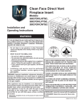
CLEARANCES TO COMBUSTIBLES
Minimum Clearances to Combustibles
3"/76mm
Minimum clearances include any projections such as shelves, window
sills, mantels, spacers/standoffs or surfaces to combustible construction
etc. above the appliance. Paint or lacquer used to finish the mantel
must be heat resistant in order to avoid discoloration.
3"/76mm
RDV CD
3"/76mm
Facing and Mantel
Side View
1-1/2”
38mm
The letters in Figure 5 (A through E) show minimum clearances required
from the appliance to combustibles and the minimum projection of the
hearth extension.
39”
991mm
33-1/2”
851mm
Insert Leveling
31-1/2”
800mm
At each front and rear corner of the insert is an adjustable leg provided
to level the insert should the hearth of the fireplace be uneven. To adjust
the legs, loosen the two 5/32" allen head screws, move the leg to the
desired height and then tighten the screws. Repeat these steps for each
adjusting leg.
Facing and Mantel Clearances
36-1/2”
927mm
Figure 4
See Figure 4
MINIMUM CLEARANCES
MINIMUM CLEARANCES TO COMBUSTIBLES........... RDV CD
A = Top Facing to Bottom of Appliance......................31-1/2" (800mm)
B = Side Facing or Side Wall to Center of Glass.......25-1/2" (648mm)
C = 10-1/2” (267mm) Mantel to Bottom of Appliance. 39" (991mm)
HEARTH PROTECTION
D = Vertical Distance from base of appliance to Hearth Extension........................................... .
E = Minimum Horizontal Distance
.
from Front of Appliance....................................... .
TRIM
FACING
0 "
2”
4”
(0mm) (51mm) (102mm)
13"
10”
0”
(330mm) (254mm) (0mm)
Left
Side
B
C
A
Right
Side
CL
D
E
Hearth Protection
NOTE: Hearth protection to be min.
3/8” (10mm) thick non-combustible
or equivalent, with a k factor of .84.
Figure 5 - Clearances
14
Front View
MANTEL
MANTEL
NOTE: DIAGRAMS & ILLUSTRATIONS ARE NOT TO SCALE.
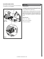
FAN CONTROL MODULE SWITCH
INSTALLATION
Before installation, verify the power switch on the Fan Control Module is
in the ON position (as shown in Figure 6).
Venting Installation
Your IHP appliance must be vented to the outside in accordance with the
current edition of the National Fuel Gas Code ANSI-Z223.1 (In Canada,
the current CAN/CGA B149.1 installation code).
This appliance requires a 3” diameter listed flex liner. The vent should
terminate with a listed direct-vent termination cap. The chimney should be
sealed around the cap to prevent air and rain from entering the chimney.
Adhere to the vent manufacturer's instructions for installation and vent
termination. These appliances are approved for use with the following
vent kits.
Simpson Dura Vent Flex Liner 3" X 35' - #3DFA-35
Adaptor w/ Flashing - #46DVA-GK
Fan Control
Module (FCM)
Termination Cap - #46DVA-VC
"ON" Position
Figure 6
15
NOTE: DIAGRAMS & ILLUSTRATIONS ARE NOT TO SCALE.
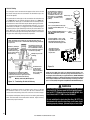
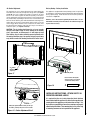
Vertical Venting
The vent pipes must be connected to the proper collars on the unit and
the exhaust vent pipe must be connected to the termination cap or the
unit will not operate.
The combustion air intake pipe can be connected to the termination cap
(see Figure 7b) or it can terminate inside the chimney (see Figure 7a).
If combustion air intake pipe is terminated inside the chimney and not
connected to the actual termination cap the bottom opening of the chimney (chimney throat) must be sealed around the vent pipes. Use a non
combustible seal-off plate (i.e. 22 gage sheet steel) or unfaced fiberglass
insulation (8 lb per square foot density minimum) to seal around the vent
pipes. Whichever “seal off” method is used must effectively seal the area
to prevent room air passage to the chimney of the fireplace. The insulation
may give off an odor during the first hour of operation.
Air Inlet
Exhaust 3" (75mm) UL
1777. A full length liner
is required from the
exhaust outlet on appliance to center collar of
termination cap.
Exhaust
NOTE: Terminating the air intake liner as shown here may not be allowed by some local codes. Check with the authority having jurisdiction
for your area.
The outside air inlet does not
require a full reline (if intake
liner is terminated in chimney
and a positive flue connection
is achieved as specified).
The existing fireplace chimneys
may take various contours
which the flexible liners will
accommodate. However, keep
the flexible liner as STRAIGHT
as possible, avoid unnecessary
bending.
Vertical Cap
Termination
Connector
Liner Requirements:
Use 3" (76 mm) diameter listed gas
vent liner (UL1777 ONLY) for the
EXHAUST
Use 3" (76 mm) diameter listed
liner (UL 181 or UL1777) for the
AIR INTAKE.
Vertical Height Min. = 10 ft. (3.1 M)
Vertical height Max. = 35 ft. (10.7 M)
Note: Measured from flue collar on
unit to the end of the vent pipe or liner
Exhaust
Intake
The flexible vent pipe
must NOT be allowed to
sag behind insert or in
fireplace flue.
Existing Fireplace Flue
(chimney)
Air Inle
t
Combustion Air Intake
Air Inlet Liner (for combustion air) When
terminating the air inlet liner at this point, a
positive flue connection is required (to ensure
combustion air is drawn down the chimney
only).
Positive Flue Connection (sealing
fireplace throat
using a noncombustible seal-off plate
or insulation).
Masonry and Factory Built Fireplaces
Figure 7a - Terminating Air Inlet in Chimney
Figure 7b
Make sure that both liners will pass through existing damper area.
Remove or lock damper to allow the passage of the flexible liners. If
the damper will not allow the passage of both liners, DO NOT PROCEED
FURTHER. (If fireplace is masonry) Consult a local mason for removal
of the damper without risk of structural damage or leakage (if the fireplace is factory built) The appliance may NOT be installed into the fireplace.
WARNING
NOTE: The minimum vertical rise (exhaust vent) is 10 feet (3.1 M) and
the maximum vertical rise is 35 feet (10.7 M). These dimensions are
measured from the starting collars of the unit to the end of the vent pipe.
The fireplace and fireplace chimney must be clean and in good working
order and constructed of non-combustible materials. Inspect chimney
cleanouts for proper fit and seal.
Direct-Vent Fireplace Insert Vent Requirements - Use liner
listed to UL181 (Factory-made Air Ducts And Air Connectors) or UL1777 (Chimney Liners) for the AIR INTAKE. Use
liner listed to UL1777 ONLY for the EXHAUST.
Do not substitute the heat-rated flex liner (UL1777) for
the exhaust with any other type liner or a fire may result
causing property damage, personal injury or loss of life.
16
NOTE: DIAGRAMS & ILLUSTRATIONS ARE NOT TO SCALE.
Zero Clearance Fireplace Installation
This appliance may be installed in a masonry or factory built/zero clearance (ZC) fireplace. When installing in a ZC fireplace, the ZC grate must
be removed and the ZC damper must be removed or secured open. The
ZC doors, screen, refractory or masonry lining, baffles and smoke shelf
may be removed if necessary to install the gas insert. However, do not cut
or alter the fireplace components. The removal of any parts to facilitate
installation must not alter the integrity of the inner or outer shells of the
fireplace cabinet. Any parts removed must be replaceable if the insert is
taken out of the fireplace or the fireplace clearly marked with a paint stick
that "This fireplace has been altered and is no longer safe to operate."
This appliance is designed to fit into a ZC fireplace with a minimum firebox
height of 19-1/2" (495mm).
If the factory-built fireplace has no gas access hole(s) provided, an access
hole of 1.5" (38.1 mm) or less may be drilled through the lower sides or
bottom of the firebox in a proper workmanship like manner. This access
hole must be plugged with a non-combustible insulation after the gas
supply line has been installed.
Si le foyer préfabriqué ne comporte pas d’orifices d’amenée du gaz,
un orifice d’au plus 38,1 mm (1,5 po) peut être pratiqué, selon les
règles de l’art, dans la partie inférieure des parois ou au fond de
la chambre de combustion. Cet orifice doit être obturé au moyen
d’isolant incombustible une fois la conduite de gaz en place.
AVERTISSEMENT
Ne pas utiliser l'appareil si le panneau frontal en
verre n'est pas en place, est craqué ou brisé.
Only doors certified with the appliance shall be used.
Seules des portes certifiées pour cet appareil doivent être
utilisées.
Do not remove glass door while the appliance is hot.
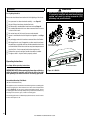
Glass Door Removal
To remove the glass door:
1. Pull latches on the bottom right and left of the door out of the slots
and place below the tab on the front door.
2. The door can now be pulled from the bottom away from the firebox
and lifted up and off the firebox.
3. To reinstall the door, complete the steps in reverse order.
The installer must mechanically attach the marking supplied with the gas
fireplace insert to the inside of the firebox of the fireplace into which the
gas fireplace insert is installed. See Figure 1 on Page 10.
Glass Door
WARNING
•Do not attempt to substitute the materials used on
these doors, or replace cracked or broken glass.
•Handle this glass with extreme care! Glass is
susceptible to damage – Do not scratch or handle
roughly while reinstalling the glass door frame.
•The glass door(s) of this appliance must only be
replaced as a complete unit as provided by the
manufacturer. Do not attempt to replace broken,
cracked or chipped glass separately.
•Do not attempt to touch the front enclosure glass
with your hands while the appliance is in use.
•Do not use abrasive cleaners. Never clean the
glass when it is hot.
•DO NOT abuse glass door by striking or slamming
shut.
See Detail A
WARNING
Do not operate the appliance with the glass front
removed, cracked or broken.
Figure 8
Detail A
DETAIL A
17
NOTE: DIAGRAMS & ILLUSTRATIONS ARE NOT TO SCALE.
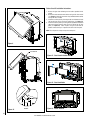
Firebox Liner Kit Installation Instructions:
1. Remove the glass door following the instructions provided in this
manual.
2. Remove the two brackets from the firebox using a 5/32" allen wrench
(see Figure 11). Retain the screws for step 4, and discard the brackets
as they will not be needed.
3. Install the rear liner panel by inserting the tabs on the bottom of each
end into the slots on the rear burner-retaining tray (see Figure 12).
4. Install one side liner panel by inserting the tab (located on the bottom
edge near the back) into the same slot as one side of the rear liner
panel (see Figure 12). Fasten in place using one screw from the
brackets removed in step 2. Repeat for the other side liner panel.
NOTE: The side panels overlap on top of the back panel.
1 - PANEL INSTALL: BRACKET REMOVAL
Figure 9
See Detail B
1 - PANEL INSTALL: BRACKET REMOVAL
Figure 11 - Panel Install: Bracket Removal
2 - PANEL INSTALLATION
1 - PANEL INSTALL: BRACKET REMOVAL
3 - PANELS INSTALLED
Figure 12 - Panel Installation
3 - PANELS INSTALLED
MEDIA
3 - PANELS INSTALLED
Figure 10
Detail
B B
DETAIL
SCALE 0.500
Figure 13 - Panels Installed
18
NOTE: DIAGRAMS & ILLUSTRATIONS ARE NOT TO SCALE.
Glass Media Installation
Surround Installation
Glass Media Kits (one required)
Cat. No.
Model
H8412
CRSHGL-RBLK
Glass Media, 5LB Bag, Reflective Black
Description
Glass Media, 5LB Bag, Reflective Blue
H8424
CRSHGL-RBLU
H8413
CRSHGL-P
Glass Media, 5LB Bag, Platinum
H8538
CRSHGL-GF
Glass Media, 5LB Bag, Goldfinger
H8539
CRSHGL-C
Glass Media, 5LB Bag, Copper
WARNING
• HANDLE MEDIA ONLY WHEN COOL. Turn OFF
all electricity to the appliance before installing
media. Media gets very HOT during fireplace use
and will remain hot up to one hour after the gas
supply is turned off.
• Any attempt to use media not specified for your
fireplace configuration will result in incomplete
combustion, sooting, and poor flame quality, and
will void the warranty.
1. Fill the provided measuring box level with the top (approximately 3
cups).
2.Distribute the measured amount of media in an even layer in the
recessed area on top of the burner (shaded area in Figure 14).
IMPORTANT!
• Do NOT mound up media.
• If using multiple colors of media, NEVER use more than one level
measuring box (approximately 3 cups) total at one time.
• If media is not installed according to the media installation instructions, flame impingement and improper combustion could occur
and result in soot and/or excessive production of carbon monoxide
(CO), a colorless, odorless, toxic gas.
The fireplace insert surround panels are made of heavy gage steel for
durability and, if desired, for the ease of making an inside fit in the fireplace. See Packaging List for available sizes.
1. Remove the speed nuts (A in Figure 15) from the parts bag and install
(with the flat surface forward) on the six holes in the surround brackets - three on each side of the insert (B in Figure 15). A flat bladed
screwdriver may help in installing the nuts.
2. Install all surround panels and trim with the appliance positioned in
the fireplace, but a few inches in front of its final location.
3. If an Arch face is to be installed on the appliance, the sight obstructor
that comes with the face must be installed prior to installing the surround panels. See the instructions included with the face for proper
sight obstructor installation.
4. Install the side surround panels by lining up the holes in the tabs on
the side surround panels in front of the holes on the surround brackets.
Next insert two slotted 1/4" truss screws for each side surround panel
and secure loosely.
5. Fasten the top surround panel with the remaining two truss screws.
Tighten all six truss screws after adjusting the surround panels to
eliminate space between side and top surround panels.
6. Assemble the surround trim by inserting the elbowed retainer in the
rectangular slot in the ends of the longest piece of trim and secure by
tightening the screw in the retainer. Slide the mitred ends of the two
side trim pieces onto the elbowed retainer and secure by tightening
the retainer screw.
7. The fastened trim pieces should now be horseshoe shaped. Slide the
trim down over the surround panels so the edge of the surround panel
fits just behind the rounded edge of the trim.
8. Install three spring clips (found in parts bag in firebox) in each piece
of trim by inserting them between the rear of the surround and the
channel of the trim. The spring clips will push the trim tight to the
surround.
A
B
B
Figure 15
C
Latches
A = Speed nuts
B = Holes in the surround brackets - three on each side
C = Location where hooked brackets on face will hang
Face Installation
The faces come with hooked brackets. To install the face, hang the hooked
brackets on the surround brackets (See C in Figure 15).
Figure 14 - Media Installed
19
NOTE: DIAGRAMS & ILLUSTRATIONS ARE NOT TO SCALE.
Gas Line Installation
After leveling, position the insert in the fireplace - holding it about six
inches out from its final location.
CAUTION: Specific hearth requirements apply (see Clearances
to Combustibles).
This appliance must be connected to the gas line in accordance with local
codes and/or the National Fuel Gas Code, ANSI Z223.1 (In Canada, the
current CAN/CGA B149.1 installation code). This appliance comes with
an 8" nipple, provided in the literature package. After connecting the gas
line, all joints in the line and connections at the valve should be checked
for leaks before final positioning of the unit. Conduct a gas leakage test
of the appliance piping and control system downstream of the shutoff
valve in the supply line to the appliance.
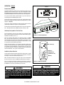
Gas Pressure Requirements
A MAJOR CAUSE OF OPERATING PROBLEMS WITH GAS
APPLIANCES IS IMPROPER GAS PRESSURE!
The most important item to check during the initial installation
and the first thing to check when operating problems occur is
gas pressure! This appliance will not function properly unless
the required gas pressure is supplied. See the table on this
page for gas pressure requirements.
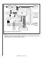
Two pressure taps are provided on the appliance's valve to check gas
pressures(see Figure 16 for locations). To check inlet pressure (with
the appliance burning), insert a small flat blade screwdriver into the tap
and turn a half turn counter-clockwise. Cover the tap with the line from
a manometer and check the pressure. Close the tap gently but securely
after completing the check. To check manifold pressure (with the appliance
burning at the high burn setting) insert a small flat blade screwdriver into
the tap and turn a half turn counter-clockwise. Cover the tap with the line
from the manometer and check the pressure. Again, close the tap gently
but securely after completing the check. Check the taps for gas leaks with
a gas leak test solution (retighten if necessary).
If the pressure is not sufficient, make sure the gas supply line is large
enough, the supply regulator is properly adjusted and the total gas load
for the residence does not exceed the amount supplied.
Propane tanks are at pressures that will cause damage to valve components. Verify that the tanks have step down regulators to reduce the
pressure to safe levels.
Fuel
Type
Inlet Pressure
Manifold Pressure
Desired
Minimum
Maximum
On Hi
Fire
On Lo
Fire
Natural
Gas
7" WC
5" WC
10.5" WC
3.5" WC
1.6" WC
LP Gas
11" WC
10.5" WC
13" WC
10" WC
6.4” WC
Stepper Motor
Pressure
Regulator
Tower
Green Wire
(From DFC Wire
Harness)
Inlet (Supply)
Pressure Tap
Outlet (Manifold)
Pressure Tap
Main Gas Inlet
3/8" NPT
Yellow Ground Wire
(From DFC Wire
Harness)
Figure 16 - SIT Proflame Electronic Valve, Stepper
LP and Natural Gas Supplies
This appliance is equipped from the factory for use with natural gas only
as specified on the Safety / Listing label attached to the appliance. This
appliance can only be operated using propane gas (LP) if a certified fuel
conversion kit, provided by IHP, is installed by a qualified service technician.
Also check the orifice size on the label which is located in the control
compartment. It must be the correct size for the fuel and altitude.
Do not run propane tank dry. Running the tank dry may cause
a hazardous condition due to pressure drop in empty tank.
Solid fuel is NOT to be used with this unit.
The appliance and its appliance main gas valve must be disconnected
from the gas supply piping system during any pressure testing of that
system at test pressures in excess of 1/2 psig (3.5 kPa).
The appliance must be isolated from the gas supply piping system
by closing its equipment shutoff valve during any pressure testing of
the gas supply piping system at test pressures equal to or less than
1/2 psig (3.5 kPa).
20
NOTE: DIAGRAMS & ILLUSTRATIONS ARE NOT TO SCALE.
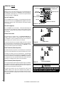
Air Shutter Adjustment
Battery Backup - Battery Installation
This appliance has an air shutter adjustment lever located behind the
lower door of the inserts face, directly above the gas valve (see Figures
17 and 18). The lever is linked to the primary air shutter on the main
burner. The air shutter regulates the amount of primary air the burner
receives and therefore how clean the insert burns. The air shutter should
only be adjusted by a qualified gas technician. The insert should burn for
about 15 minutes with the glass media installed before adjusting the air
shutter. More air will result in shorter flames and less color, less air will
result in bigger flames and more color. To adjust the air shutter, move
the adjustment lever toward or away from you using a screw driver or
needle nose pliers. (see Figures 17 and 18).
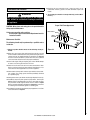
This appliance is equipped with a battery backup system. It requires four
(4) "AA" batteries, not provided, to power the appliance (without the blower)
during a power outage. Install the batteries into the battery holder per
instructions in Figure 19.
Batteries, even if not used, will gradually drain over time. It is recommended to annually check the batteries for sufficient charge and
replace when necessary.
CAUTION: The air shutter should never be set so as to make
the tips of the flames sooty or create sooting on the viewing
glass, glass media, or firebox panels. If soot begins to form
after burning, the air shutter should be opened gradually until
the sooting condition stops. Gas quality and gas pressure may
vary, which can affect the burning characteristics of the insert.
SHUTTER ADJUSTMENT DETAIL
ON
BURNER
AUTO
PILOT
TOTAL
COMFOR
CONTRO T
L
See Shutter
SEE DETAIL
A
Adjustment Detail
(Figure 18)
Figure 17
DETAIL A
SHUTTER ADJUSTMENT DETAIL
SCALE 0.600
Battery Holder
Ensure Positive and Negative
ends of the battery are installed
as indicated in battery holder
Figure 19
-
AA Battery
+
INSTALLER INSTRUCTIONS - ATTACH SAFETY-INOPERATION WARNING LABELS
DETAIL A
Pulling the adjustment lever towardDETAIL
you will
open
A
the shutter, pushing it away will SCALE
close0.600
the shutter.
It is required that the set of safety instruction labels that have
been furnished with the appliance be affixed to the operation and
control points of the appliance per the instructions on Page 7. It is
the installers responsibility to ensure these warnings are properly
affixed during installation. These warning labels are a critical step
in informing consumers of safe operation of this appliance.
Figure 18 - Shutter Adjustment Detail
21
NOTE: DIAGRAMS & ILLUSTRATIONS ARE NOT TO SCALE.
OPERATION
WARNING
Pre-Lighting Checklist
Be sure to check these items before the initial lighting of the insert:
cGas pressure has been checked carefully - see Page 20.
cAll gas fittings have been checked for leaks.
cAll clearances to combustibles have been met-see Page 14.
cAll combustible materials have been removed from the area
in front of the insert.
cAll vented areas of the insert face are unobstructed.
cHouse is ventilated to clear initial paint curing odors - see Page
25.
cAll packaging materials have been removed from the firebox.
cWhile appliance is cool, fingerprints or other marks have been
cleaned from any plated surfaces with denatured alcohol and a
soft cloth. Marks left on these surfaces may become permanent
into the finish if not removed prior to burning the unit.
cFirebox liner panels and glass media have been installed.
cThe glass door is in place and is properly sealed.
• Operation of this appliance when not connected
to a properly installed and maintained venting
system can result in carbon monoxide (CO)
poisoning and possible death.
Electronic Pilot
Assembly
Electronic Gas Control Valve
SIT Proflame, Stepper
ON
BURNER
TOTAL T
COMFORL
CONTRO
Operating Instructions
AUTO
PILOT
See Page 36 for operating instructions.
Unit-Mounted Controls
IMPORTANT NOTE: When opening the lower door on the face
while the insert is burning, pull at the far left or far right
vent openings, because the door is hot during operation.
Figure 20 - RDV CD
Intermittent/Standing Pilot Mode
(On/Auto Pilot Mode Switch)
This appliance can be switched from intermittent ignition to a standing pilot
simply by toggling the switch located in the lower control compartment
(refer to Figure 20). To save energy, switch to intermittent mode. To have
a standing pilot which will help startup during cold climate conditions by
warming the flue and the glass, switch to standing pilot.
The standing pilot mode is indicated by a pilot that comes on and remains
lit when the fireplace is off.
22
NOTE: DIAGRAMS & ILLUSTRATIONS ARE NOT TO SCALE.
OPERATION - RDV CD
Receiver
Remote Control System
REMOTE OFF
ON
The Remote and Receiver allows you to command the functions of your
appliance from the comfort of your chair and is configured to control
the On/Off primary burner operation, its flame levels (through six levels)
and provides On/Off and Smart thermostatic control of the appliance.
PRG
The system controls blower speed through six (6) levels and has a
constantly powered 120V/60Hz power outlet.
The Receiver connects directly to the gas valve, stepper motor and the
Blower Control Module with and umbilical cord wiring harness (see Wire
Diagram on Page 26).
The Receiver accepts commands via radio frequency from the Remote
(transmitter) and does not require line-of-sight operation.
The Receiver three position slider switch can be set to one of three positions: ON (Manual Override), REMOTE (Remote Control) or OFF.
ON
BURNER
TOTAL T
COMFORL
CONTRO
AUTO
PILOT
Initializing The System For The First Time
Install 4 AA batteries into the receiver battery bay (behind the switch
plate). Note the polarity of the battery and insert into the battery bay as
indicated on the Battery cover (+/-).
ON / AUTO
Pilot
Figure 21 - Control Compartment
Place the 3 position slider switch in the "Remote" position (see Figure
21). Using the end of a paper clip, or other similar object, insert the
end of the paper clip into the hole marked "PRG" on the Receiver front
cover. The Receiver will "beep" three (3) times to indicate that it is ready
to synchronize with the Remote (transmitter).
Install 3 AAA type batteries in the Remote (transmitter) battery bay,
located on the base of the Remote. With the batteries already installed
in the Remote, push the ON button. The Receiver will “beep” four times
to indicate the Remote’s command is accepted and sets to the particular
code of that Remote. The system is now initialized.
Blue LCD Display
ON/OFF Key
Low Battery Power Detection
THERMOSTAT Key
The life span of the Receiver batteries depends on various factors: quality
of the batteries used, the number of ignitions of the appliance, the number
of changes to the room thermostat set point, etc.
UP/DOWN Arrow Key
MODE Key
When the Receiver batteries are low, two “beeps” will be emitted from
the Receiver when it receives an ON/OFF command from the Remote.
This is an alert for a low battery condition for the Receiver. When the
batteries are replaced the “beep” will be emitted from the Receiver when
the ON/OFF key is pressed (See Initializing The System).
Figure 22 - Remote (transmitter)
CAUTION
WARNING
Fire hazard. Can cause severe injury or death.
The receiver causes ignition of the appliance. The
appliance can turn on suddenly. Keep away from
the appliance burner when operating the remote
system or activating manual bypass of the remote
system.
Property damage hazard. Excessive heat can cause
property damage. The appliance can stay lit for many
hours. Turn off the appliance if it is not going to be
attended for any length of time. Always place the
Transmitter where children can not reach it.
23
NOTE: DIAGRAMS & ILLUSTRATIONS ARE NOT TO SCALE.
OPERATION - RDV CD
Child Safety Lock-Out
Transmission
Low Battery Alarm
Temperature Indicator Display
With the system in the “OFF” position, press the Thermostat Key and
the Mode Key at the same time (see Figure 22). Look at the LCD screen
on the Remote to verify that a C or F is visible to the right of the Room
Temperature display (see Figure 23).
Turn On The Appliance
Press the ON/OFF Key on the Remote. The Remote display will show all
active Icons on the screen (see Figure 23) and the appliance main burner
will turn on. A single “beep” from the Receiver will confirm reception
of the command.
Thermostat
Off/On/Smart
Room Temperature
OFF
ON
SMART
Set Point
Temp./Level/State
Blower Control
Flame On
MAX
MAX
Maximum Level Indicators
Figure 23 - Indicator Icons
Turn Off The Appliance
Press the ON/OFF Key on the Remote. The Remote LCD display will
only show the room temperature and Icon and the appliance burner
will turn off. A single “beep” from the Receiver confirms reception of
the command.
Remote Flame Control
The system has six (6) flame levels. See Figures 24 and 25 for an
example. With the system on, and the flame level at the maximum
in the appliance, pressing the Down Arrow Key once will reduce the
flame height by one step until the flame is turned off.
The Up Arrow Key will increase the flame height each time it is pressed.
If the Up Arrow Key is pressed while the system is on but the flame is
off, the flame will come on in the high position (see Figure 25). A single
“beep” will confirm reception of the command.
Figure 24
Flame Level 5
Room Thermostat (Remote Operation)
The Remote Control can operate as a room thermostat. The thermostat
can be set to a desired temperature to control the comfort level in a room.
To activate this function, press the Thermostat Key. The LCD display
on the Remote will change to show that the room temperature is “ON”
and the set temperature is now displayed (see Figure 23). To adjust the
set temperature, press the Up or Down Arrow Keys until the desired set
temperature is displayed on the LCD screen of the Remote.
Smart Thermostat (Remote Operation)
The smart Thermostat function adjusts the flame height in accordance
to the difference between the set point temperature and the actual room
temperatures. As the room temperature gets closer to the set point, the
Smart Function will modulate the flame down.
To activate this function, press the Thermostat Key until the word
“SMART” appears to the right of the temperature bulb graphic. To
adjust the set temperature, press the Up or Down Arrow Keys until the
desired set temperature is displayed on the LCD screen of the Remote
(see Figure 23).
Figure 25
Flame Level Maximum
WARNING
THE REMOTE (TRANSMITTER) AND RECEIVER ARE RADIO
FREQUENCY DEVICES. PLACING THE RECEIVER IN OR NEAR
METAL MAY SEVERELY REDUCE THE SIGNAL RANGE.
24
NOTE: DIAGRAMS & ILLUSTRATIONS ARE NOT TO SCALE.
OPERATION - RDV CD
Burner Flame Appearance
Blower Speed Control
This appliance is equipped with a hot air circulating blower. The speed
of the blower is controlled by the Remote. The blower speed can be
adjusted through six (6) speeds.
To activate this function use the Mode Key to index to the blower control
icon (see Figures 22 and 23). Use the Up/Down Arrow keys to turn on,
off or adjust the blower speed. A single “beep” will confirm reception
of the command.
NOTE: The blower can be controlled only by the remote. Turning the
appliance off with the unit mounted three position slider switch (Figure
21) will NOT turn off the blower. To turn off the blower, use the remote
in lieu of or prior to shutting the appliance off at the three position slider
switch (Figure 21).
Blower speed will be indicated by either an Off, Level Bar, or HI shown
in the Set Point/Temp/Level/State indicator area.
Key Lock
This function will lock the keys to avoid unsupervised operation. To
activate this function, press the MODE and UP keys at the same time.
To de-activate this function, press MODE and UP Keys at the same time.
Manual Bypass Of The Remote System
If the batteries of the Receiver or Remote are low or depleted, the appliance can be turned on manually by sliding the three position slider switch
to the ON position. This will bypass the remote control feature of the
system and the appliance main burner will come on.
OPERATION - RDV CD
Soot at
Flame Tip
Dark Orange
Flame
No Blue Flame
Center
Soot above
Flame Tip
Ports on Pan
Burner Assembly
IMPROPERLY
BURNING FLAME
No Soot at
Flame Tip
Semi-Transparent
Yellow Flame
Blue Flame
Center
PROPERLY
BURNING FLAME
Figure 26
Paint Curing
This appliance has been painted with a high temperature metallic stove
paint. It leaves the factory dry to the touch, but finishes curing as the
appliance is used. Fire the appliance four successive times for ten minutes
each time with a five minute cool down between each firing. Ventilate the
house during these first firings as the paint gives off an unpleasant odor.
It is recommended that persons sensitive to an imbalance in the indoor
air quality avoid the appliance during the curing process.
Quiet Operation
As the appliance is burning, a number of normal operational sounds may
be heard. The flow of gas through the gas valve and orifice may make a
rushing or whistling noise. If this noise is objectionable, it can be reduced
by turning down the flame. Turning down the flame can reduce total heat
output by more than 30%. When the blower turns on, the sound of rushing air may be heard. The blower sounds may be reduced by adjusting
the speed of the blower assembly. Also, a slight clicking sound may be
heard as the gas valve or blower switch turn on and off.
Flame Color and Behavior
This appliance is designed for maximum heating efficiency. Therefore,
upon lighting of the main burner the flames will be semi-transparent or
“bluish.” After 10-20 minutes of operation the insert will heat up and the
flames will become a yellow/orange color.
Adjusting the appliance to cause the flames to turn orange sooner may
result in poor combustion, sooting and a hazardous situation. See Figure
26 showing proper flame appearance.
When testing for proper operation - If an optional thermostat is installed
adjust it to its highest temperature setting. Visually determine that main
burner gas is burning properly: i.e., no floating, lifting or flashback.
Adjust the primary air shutter(s) as required. Check for proper main
burner operation at both high and low flame.
25
NOTE: DIAGRAMS & ILLUSTRATIONS ARE NOT TO SCALE.
BLK
POWER
ADAPTOR BOX
120 V AC
FAN CONTROL
MODULE
GRN
ROOM AIR BLOWER
WHT
1
2
3
14 - RED
4 - PUR
3 - GRAY
ORG
PILOT
BURNER
CONTROL
BOARD
WHT
YLW
NOTE: SWITCH CONDITIONS
GIVEN AT ROOM TEMPERATURE
BLK
9
8
7
6
5
4
3
2
1
4-GRN
9 - YLW
3-BLK
VALVE
8 - GRN
WHT
N/C = NORMALLY CLOSED
N/O = NORMALLY OPEN
= FEMALE DISCONNECT
= MALE DISCONNECT
= STUD CONNECTION
2-RED
7 - ORG
5 - BLUE
1
4
6 - WHT
10 - ORG
11 - YLW
8-GRN
12 - BRN
2-BLK
13 - BLK
9-WHT
PILOT
ON/AUTO
SWITCH
AUTO-RESET
TEMPERATURE
SWITCH
N/O
1-RED
REMOTE RECEIVER
NOTE: SWITCH CONDITIONS
GIVEN AT ROOM TEMPERATURE
N/C = NORMALLY CLOSED
N/O = NORMALLY OPEN
Figure 27 - Electronic Control Schematic - Models RDV CD
= FEMALE DISCONNECT
= MALE DISCONNECT
= STUD CONNECTION
CAUTION: Label all wires prior to disconnection when servicing controls. Wiring errors can cause improper and dangerous operation.
ATTENTION: Au moment de l'entretien des commandes, étiquetez tous les fils avant de les débrancher. Des erreurs de
cáblage peuvent entraîner un fonctionnement inadéquat et dangereux.
26
NOTE: DIAGRAMS & ILLUSTRATIONS ARE NOT TO SCALE.
o
Check that the area around the insert is kept clear and is free of
combustible materials, gasoline and other flammable vapors and
liquids.
MAINTENANCE AND SERVICING
WARNING
Turn off gas and electrical power to the fireplace
and allow it to cool before cleaning or servicing
the appliance.
2.The viewing glass should be cleaned periodically (see Glass Maintenance).
Proper Pilot Flame Appearance
CAUTION: Wear gloves and safety glasses for protection while
doing required maintenance.
Verify proper operation after servicing.
S'assurer que l'appareil fonctionne adéquatement une fois
l'entretien terminé.
Flame Sensor
Igniter
Electrode
Maintenance Checklist
The following should only be performed by a qualified service
technician.
1.Annual inspection should be made and the following checks performed:
Figure 28
o
When unit is cool, remove glass and inspect burner for dirt, soot and
lint accumulations and remove if necessary. Before cleaning the burner,
remove and clean the media following the instructions on Page 28.
If excessive soot accumulation is present on burner, have a qualified
service technician adjust the burner for proper combustion.
o
Clean inside of glass with gas fireplace glass cleaner. NEVER attempt
to remove or clean the glass when the unit is hot.
o
Check the hot air outlet vents for lint or other accumulations. Never
block or restrict vent openings, obstruct flow of ventilation air, or use
vents other than those approved for use with this appliance.
o
Check that the chimney and its outlet are open and free of soot, blockage, or debris. The venting system should be periodically examined
by a qualified agency.
o
Check gaskets once a year. Gaskets must be tight. Replace if necessary.
o
Periodically inspect the pilot system for proper flame. Turn the pilot
ON/Auto switch to the ON position. Ensure the igniter lights the pilot.
The pilot flame should engulf the flame sensor as shown in Figure
28. See Intermittent/Standing Pilot Mode on Page 22 for instructions
on switching from intermittent ignition to a standing pilot.
o.
Periodically inspect the burner flame for proper appearance. See Flame
Color and Behavior on Page 25.
27
NOTE: DIAGRAMS & ILLUSTRATIONS ARE NOT TO SCALE.
Glass Door Cleaning and Maintenance
Blower Removal
Cleaning: Do not remove or clean the glass door when hot. When cool,
Unplug the power supply cord from the electrical outlet prior to removing
the blower. The blower can be accessed through the back wall of the firebox.
the glass may be cleaned with a clean, soft cloth and a household glass
cleaner. For cleaning white condensation from the interior glass, use
a gas fireplace glass cleaner available from your dealer. Use of caustic
or abrasive cleaners may damage the glass. DO NOT spray commercial
glass cleaner with ammonia on the door and glass gasket as it may dissolve the gasket glue.
WARNING
• DO NOT use abrasive cleaners on glass.
• DO NOT clean glass when hot.
Repair: If the glass is broken in the glass door, the entire door (metal
frame, gasket and glass) should be replaced as a unit. This replacement
glass door is available from your IHP dealer. Do not use substitute parts
or materials. The glass is neo-ceramic and alternative types must not
be used.
NOTE: BE CAREFUL NOT TO SPRAY COMMERCIAL GLASS
CLEANER WITH AMMONIA ON GASKET AREA OF DOOR. AMMONIA WILL DISSOLVE GASKET GLUE.
Fuel Conversion
Remove the insert face, glass door, firebox panels, glass media, burner
assembly, and front and rear media trays.. All of these items are fragile
so handle them with care. Next, remove the five allen head screws around
the outside of the panel fastened to the back wall of the firebox. Rotate
the top of this panel toward the front, remove the two wires connected
to the blower and then lift the panel with the blower attached out of the
firebox. Remove the blower assembly by removing the two screws holding it to the panel bracket. To reinstall the blower, repeat these steps in
the reverse order.
Electrical Requirements:
This appliance is equipped with an electronic valve and electronic pilot
ignition system (which can be switched from Intermittent to standing
pilot mode - see Page 22). External electrical 120 Volt power is required
to operate the blower system of this appliance and recommended to operate the burner system. This appliance is equipped with a battery backup
system in case of a power outage (see Battery Backup on Page 21 for
more information).
This appliance, when installed, must be electrically grounded in accordance
with local codes, or in the absence of local codes, the National Electrical
Code ANSI/NFPA 70-latest edition, or the Canadian Electrical Code, Part
1, CSA C22.1-latest edition. (See Operating Options for burner ON/OFF
switch information).
Converting this appliance between natural gas and propane (LP) can be
accomplished by installing a gas conversion kit. Only a qualified service
technician should perform the conversion.
Gas Conversion Kits: Please see instructions provided with
conversion kit.
Removing And Cleaning Media
CAUTION: Risk of personal injury. Allow media to completely
cool before handling.
To remove glass media from appliance (for cleaning or replacement):
Use a clean, dry, empty shop vac.
1. Place media in colander or sieve, and carefully rinse under
hot water.
2. Allow media to air dry before reinstalling.
28
NOTE: DIAGRAMS & ILLUSTRATIONS ARE NOT TO SCALE.
Replacing A Damaged Barrier
• If the barrier becomes damaged, the barrier shall be replaced
with the manufacturer’s barrier for this appliance.
• For use with barrier Part No. J7510 (Contemporary Facade)
or J7511 (Cast Pillar Facade). Follow installation instructions.
Removing The Damaged Barrier
Contemporary Facade (see Figure 29)
1. Make sure the unit is off and cold.
2. Remove the contemporary facade from the unit by gripping both sides
firmly and lifting up slightly and then out, away from the unit.
3.Lay the facade face down on a soft surface that will not scratch the
paint.
4. Using a 3/8” socket, remove the six nuts holding the left (1) and right
(2) sight obstructer.
5. Remove the barrier.
Installation is the reverse of removal:
Barrier
2
1
Horizontal Bar Ends
See Detail A
1. Replace barrier with Part No. J7510.
2. Place sight obstructers back over the threaded studs taking note that
the upper and lower horizontal bar ends line up with grooves in sight
obstructers (see Detail A in Figure 29).
3. Reinstall the 3/8” nuts.
4. Reinstall facade to the unit.
Detail A
Figure 29 - Contemporary Facade
Cast Pillar Facade (see Figure 30)
1. Make sure the unit is off and cold.
2. Remove the cast pillar facade door from the facade by gripping both
sides firmly and lifting up slightly and then out, away from the side
pillars.
3. Lay the door face down on a surface that will not scratch the paint.
4. Using a Phillips head screwdriver, remove the 18 screws holding the
barrier to the door.
5. Remove the barrier.
Installation is the reverse of removal:
1. Replace barrier with Part No. J7511
2. Replace all Phillips head screws removed in step 5.
3. Replace the four socket head screws removed in step 4.
4. Reinstall door onto facade.
Barrier
Figure 30 - Pillar Cast Facade
NOTE: DIAGRAMS & ILLUSTRATIONS ARE NOT TO SCALE.
29
TROUBLESHOOTING
NOTE: When troubleshooting the gas control system, be sure the external gas shut off valve, located at the gas supply inlet is in
the “ON” position.
IMPORTANT: Call your gas supplier or plumber for additional help with any gas control problem. Valve system troubleshooting
should only be accomplished by a qualified service technician.
SYMPTOM
Thin black coating (soot)
forms on the viewing
glass, firebox panels, or
glass media.
PROBABLE CAUSE
CORRECTIVE ACTION
Too much or improper
placement of glass
media.
See Firebox Liner Kit and Glass Media Installation on Pages 18 and 19.
Improper air shutter
setting
Check for debris obstructing air flow in valve compartment under insert or in front of
lower venting.
If sooting continues open air shutter (see Air Shutter Adjustment on Page 21).
Not enough combustion air
Humming or whistling
coming from insert.
A change in flame appearance or burner operation.
The main Burner comes
on but then goes out.
Normal operating noise
See Quiet Operation on Page 25. The noise may be reduced by slightly turning down the
flame. Turning the flame down will reduce the heat output of the appliance.
Obstructed orifice
opening
If noise is excessive or is “whistling” have your gas supplier check the regulator and
orifices and replace if necessary.
A change in gas pressure
Have your gas supplier check for correct inlet gas supply pressure (7" W.C. / po. C.E.
[1.74 kPa] natural gas; 11" W.C. / po. C.E. [2.74 kPa] LP gas). NOTE: NEVER BLOCK OR
OBSTRUCT AIR INTAKE OR OUTLET VENTS.
Too much or improper
placement of glass
media.
See Firebox Liner Kit and Glass Media Installation on Pages 18 and 19.
Gas is not reaching the
appliance.
Check the gas supply and gas shutoff valves.
Loose wires to the valve
or ignition module.
Check control compartment for any obvious loose wiring (call a service technician if required).
Pilot flame is not engulf- Call for a service technician.
ing the sensor.
30
Obstructed vent system.
Call for a service technician.
Nothing happens when
the appliance is turned
On/Off.
Gas is not reaching the
appliance.
Check the gas supply and gas shutoff valves.
Appliance is not receiving power.
Check/replace back-up batteries (see Battery Backup on Page 21).
Check building circuit breakers to ensure power is on to the appliance.
Check Fan Control Module power switch to ensure power is on (see Figure 6 on Page 15).
The main burner does
not light and the igniter is
sparking.
Gas is not reaching the
appliance.
Check the gas supply and gas shutoff valves.
Loose wires to the
valve.
Check control compartment for any obvious loose wiring (call a service technician if required).
Loose wires to ignition
module.
Check control compartment for any obvious loose wiring (call a service technician if required).
Air in the gas line.
Purge gas line of air (call a service technician if required).
REPLACEMENT PARTS - RAVENNA™ CD
Item #
Cat. #
26
H8859
Cassette Assembly NG 32,000 BTU (if LP, also
requires H8858 Conversion Kit)
27
H8490
3/8" NPT Pipe Nipple, 8"
Description
29
H5924
Orifice, Main Burner #36 NG 32,000 BTU
H5964
Orifice, Main Burner #53 LP 27,000 BTU
1
H8857
Media Tray
29
2
H8502
Left Face Hanging Bracket with Mounting Screws
31
H8491
Pilot Assembly Convertible, NG or LP
32
H8509
Gas Control Valve, TCC/CD Auto Hi/Lo Regulator, NG
(if LP, also requires H8858 LP Regulator)
---
H8458
Gas Conversion Kit, TCC/CD Auto Hi/Lo Regulator,
LP to NG
---
H8858
Gas Conversion Kit, CD Auto Hi/Lo Regulator, NG to
LP
4
H8492
Flue Collar Kit
5
H5723
Air Intake Kit
6
H8501
Right Face Hanging Bracket with Mounting Screws
7
H5727
Leveling Leg Kit - 2 legs with Screws
8
H8500
Door Latch Assembly
9
H8503
RDV Blower Mounting Assembly
33
H5752
Wire Grommet
10
H8499
Firebox Door Assembly with Glass
34
H8497
Hook and Loop Dot Kit - 4 sets
11
H8856
RDV CD Burner Assembly
36
H8651
TCC/CD Power Adaptor Box Assembly
13
H8505
RDV TCC/CD Control Panel
37
H8650
Convection Air Deflector
14
H8482
Heat Shield, Fan Control Module
38
J7510
Barrier (on Contemporary facade)
15
H8483
Blower Snap Switch, 160°-20°F
39
J7511
Barrier (on Pillar Cast facade)
16
H3077
Power Cord, C13 End
---
H5989
Hardware Package
17
H8493
RDV Blower with Mounting Screws
---
H8518
Gasket Kit
21
H7272
Ignition Control Board
---
H8159
Touch-Up Paint, Metallic Black (12 oz aerosol)
22
H7277
Remote Receiver, GT/GTMF, Replacement
---
H7275
Remote Control, GTMF, Replacement
23
H5744
On/Off Switch, Pilot Mode
25
H7274
Fan Control Module
---
H8484
Pilot Ground Wire
---
H8489
Ignition Control Board & GTMF Remote Receiver
Wirng Harness 18"
---
H8496
RDV TCC/CD Blower Wiring Harness
Contact an IHP dealer to obtain any of these parts. Please contact IHP
for the phone number of your nearest IHP dealer.
WARNING
Never use substitute materials. Use of non-approved
parts can result in poor performance and safety
hazards.
WARNING
Failure to position the parts in accordance with these
diagrams or failure to use only parts specifically
approved with this appliance may result in property
damage or personal injury.
AVERTISSEMENT
Risque de dommages ou de blessures si les pièces
ne sont pas installées conformément à ces schémas
et ou si des pièces autres que celles spécifiquement
approuvées avec cet appareil sont utilisées.
31
REPLACEMENT PARTS - RAVENNA™ CD
11
11
27
27
26
26
37
36
22
4
4
5
5
15
15
66
77
11
10
10
99
17
17
16
16
8
31
31
38
29
29
Facade
32
32
25
14
36
33
21
34
22
39
Cast Pillar
Facade Door
32
NOTE: DIAGRAMS & ILLUSTRATIONS ARE NOT TO SCALE.
23
13
ACCESSORIES - RAVENNA™ CD
Product Reference Information
Cat. No.
Description
Ship.
Weight
Ship.
Volume
H8854
RAVENNA CD
144 lb.
16.9 cu. ft.
Porcelain Panel Kit
(required accessory)
Gas Conversion
Kits
RDV33
Cat. No.
Model
Description
H8458
RDV-CK-TCC-LP to NG
LP to NG Conversion Kit
H8459
RDV-CK-CD-NG to LP
NG to LP Conversion Kit
Black Porcelain
Cat. No.
Model
H8855
RDV-BLK-PCLPNL
Finish Panels/front Supports
Description
RAVENNA CD - Black Porcelain Panels
Glass Media Kits (required accessory)
Reflective Black
Reflective Blue
Platinum
H8412
CRSHGL-RBLK
Reflective Black
H8424
CRSHGL-RBLU
Reflective Blue
H8413
CRSHGL-P
Platinum
H8538
CRSHGL-GF
Goldfinger
H8539
CRSHGL-C
Copper
Goldfinger
75253
RDV-DBV ZC
STD SPPT
"ZC Lower Finish Panel/Reg Face Support
*Requires Trim Pieces below"
75251
GFHKET-B
Extended Side Trim, Black
75062
GFHKET-G
Extended Side Trim, Gold
75063
GFHKET-N
Extended Side Trim, Nickel
Copper
33
NOTE: DIAGRAMS & ILLUSTRATIONS ARE NOT TO SCALE.
Surround Trim Kits
Pillar Cast Face Kits u
Note: 3 boxes to
complete face
37-5/8" W x 23-3/4" H
H5143
GFT2941-B
Trim/Black 29" x 41"
H5145
GFT2948-B
Trim/Black 29" x 48"
H5144
GFT3341-B
Trim/Black 33" x 41"
H5146
GFT3348-B
Trim/Black 33" x 48"
75036
GFT2941-G
Trim/Gold 29" x 41"
75038
GFT2948-G
Trim/Gold 29" x 48"
75040
GFT3341-G
Trim/Gold 33" x 41"
75042
GFT3348-G
Trim/Gold 33" x 48"
75037
GFT2941-N
Trim/Nickel 29" x 41"
75039
GFT2948-N
Trim/Nickel 29" x 48"
75156
RDV-DBV-PCFP3044-TOP
75041
GFT3341-N
Trim/Nickel 33" x 41"
75157
RDV-DBV-PCFP3044-SIDES
75043
GFT3348-N
Trim/Nickel 33" x 48"
F2324
PILCST-GLASS-BARRIER Cast Door (Box 1 of 3)
75092
PILCST-PILRS2
75094
PILCST-GRL-TRD3
Grill/bars Traditional (Box 3 of 3)
75091
PILCST-GRL-FIL3
Grill/filigree Ornate (Box 3 of 3)
RDV-DBV-FP2941-C1
29" x 41" BLACK Trim (One-piece)
H8521
RDV-DBV-FP2941-C
29" x 41" BLACK Trim
H8522
RDV-DBV-FP2948-C
29" x 48" BLACK Trim
H8523
RDV-DBV-FP3341-C
33" x 41" BLACK Trim
H8524
RDV-DBV-FP3348-C
33" x 48" BLACK Trim
Top (Box 1 of 2)
Sides (Box 2 of 2)
45-1/2” (1156mm)
7-1/8”
(181mm)
44-1/2” (1130mm)
u Cast Surround Assembly For
30”
(762mm)
Pillared Face Dimensions
22-7/8”
(581mm)
Contemporary Facade Kits
With Barrier
44” (1118mm)
F2322
RDV-CONTF-BLK
Contemporary Facade - Black
F2323
RDV-CONTF-MNK
Contemporary Facade - Mink
Or
Cast Black Surround Panels (see drawing below)
Surround Panel Kits (required accessory)
H8520
Back, Pillars, Top (Box 2 of 3)
34
NOTE: DIAGRAMS & ILLUSTRATIONS ARE NOT TO SCALE.
SAFETY / LISTING LABEL - RAVENNA™ CD
MODEL
C
SERIAL
NO.
Ravenna™ CD
MODÈLE
RDV CD
C
MANUFACTURED BY:
INNOVATIVE HEARTH PRODUCTS
1502 14TH ST NW
AUBURN, WA., USA 98001
US
Report No. 14-192
FACTORY EQUIPPED FOR NATURAL GAS. IF CONTROL PANEL CONTRADICTS THIS LABEL, UNIT FUEL TYPE HAS BEEN CONVERTED.
VENTED GAS FIREPLACE HEATER - NOT FOR USE WITH SOLID FUEL
CONFORMS TO ANSI Z21.88-2014/CSA 2.33-2014 AND CAN/CGA-2.17-M91 (R2009).
THIS APPLIANCE MUST BE INSTALLED IN ACCORDANCE WITH LOCAL CODES, IF ANY. IF NOT, FOLLOW THE CURRENT ANSI Z223.1/NFPA
54-LATEST EDITION (USA) OR CAN/CGA B149.1-LATEST EDITION (CANADA). THIS APPLIANCE MUST BE INSTALLED IN ACCORDANCE
WITH THE MANUFACTURER’S INSTALLATION INSTRUCTION. FOR INSTALLATION IN SOLID FUEL BURNING FIREPLACES ONLY - MASONRY
OR FACTORY BUILT. THIS VENTED GAS FIREPLACE HEATER IS NOT FOR USE WITH AIR FILTERS.
THIS APPLIANCE IS ONLY FOR USE WITH THE TYPE OF GAS INDICATED ON THE RATING PLATE AND MAY BE INSTALLED IN AN
AFTERMARKET, PERMANENTLY LOCATED, MANUFACTURED HOME (USA ONLY) OR MOBILE HOME, WHERE NOT PROHIBITED BY LOCAL
CODES. SEE OWNER’S MANUAL FOR DETAILS. THIS APPLIANCE IS NOT CONVERTIBLE FOR USE WITH OTHER GASES UNLESS A
CERTIFIED KIT IS USED.
DANGER: RISK OF ELECTRICAL SHOCK. DISCONNECT POWER BEFORE SERVICING UNIT.
IF ELECTRICALLY CONNECTED, CONNECTIONS AND GROUNDING MUST BE IN ACCORDANCE WITH LOCAL CODES, IF ANY. IF NOT,
FOLLOW THE CURRENT NATIONAL ELECTRICAL CODE ANSI/NFPA 70-LATEST EDITION (USA) OR CSA C22.1-LATEST EDITION (CANADA).
MINIMUM FIREPLACE SIZES REQUIRED ....................
Front Opening...................................................................
Height .................................................................................
Rear Width ........................................................................
Depth .................................................................................
Ravenna CD
31.50” (800mm)
19.50” (495mm)
18.00” (457mm)
16.00” (406mm)
MINIMUM CLEARANCES
MANTEL
MANTEL
TRIM
FACING
B
MINIMUM CLEARANCES TO COMBUSTIBLES
A = Top Facing to Bottom of Appliance ..................... 31.5" (800mm)
B = Side Facing or Side Wall to Center of Glass ...... 25.5" (648mm)
* C = 10.5” (267mm) Mantel to Bottom of Appliance . 39" (991mm)
C
A
CL
D
HEARTH PROTECTION
D = Vertical Distance from base of appliance
0"
2”
4”
to Hearth Extension .......................................... (0mm) (51mm) (102mm)
E
E = Minimum Horizontal Distance
13"
10”
0”
from Front of Appliance.................................. (330mm) (254mm) (0mm)
*See owner’s manual for additional mantel clearances and options.
Note: Hearth protection to be min.
3/8” (10mm) thick non-combustible
or equivalent, with a k factor of .84.
RATINGS
Ravenna CD (RDV CD)
MAX/MIN INPUT BTUH 0-2,000 FT (0-610 M)*
NATURAL GAS
LP GAS
32,000/21,000
27,000/21,000
3.5
10.0
MIN. INLET PRESSURE (IN. WC)
5.0
10.5
ORIFICE (DMS) 0-2,000 FT (0-610 M)*
#36
#53
MANIFOLD PRESSURE (IN. WC)
US
Rapport nº 14-192
For use only with barrier Part
No. J7510 (Contemporary
Face) or Part No. J7511 (Cast
Pillar Face). Follow installation
instructions.
SERIAL Le numéro de série est indiqué dans la
NO. section anglophone de cette étiquette
Ravenna™ CD
FABRIQUÉ PAR:
INNOVATIVE HEARTH PRODUCTS
1502 14TH ST NW
AUBURN, WA., USA 98001
CET APPAREIL EST MUNI D’ÉQUIPEMENT POUR L’USAGE DU GAZ NATUREL. SI L’ÉTIQUETTE DU PANNEAU DES COMMANDES CONTREDIT CETTE
ÉTIQUETTE, C’EST QUE LE TYPE DE CARBURANT DE CET APPAREIL A ÉTÉ CONVERTI.
FOYER AU GAZ À ÉVACUATION - NE PAS UTILISER AVEC DU COMBUSTIBLE SOLIDE.
CONFORME AU STANDARD ANSI Z21.88-2014/CSA 2.33-2014 ET CAN/CGA-2.17-M91 (R2009).
CET APPAREIL DOIT ÊTRE INSTALLÉ CONFORMÉMENT AUX EXIGENCES DES CODES RÉGIONAUX ET DU CODE D’INSTALLATION ANSI
NFPA 54-DERNIÈRE ÉDITION (ETATS-UNIS), OU CAN/CGA-B149.1-DERNIÈRE ÉDITION (CANADA). CET APPAREIL DOIT ÊTRE INSTALLÉ
SELON LES DIRECTIVES D’INSTALLATION DU FABRICANT. POUR INSTALLATION DANS DES FOYERS À COMBUSTIBLE SOLIDE
SEULEMENT - DE MAÇONNERIE OU PRÉFABRIQUÉ EN USINE. CE FOYER RADIANT AU GAZ À ÉVACUATION N’EST PAS CONÇU POUR ÊTRE
UTILISÉ AVEC DES FILTRES À AIR.
CET APPAREIL DOIT ÊTRE UTILISÉ AVEC LE TYPE DE GAZ INDIQUÉ SUR LA PLAQUE SIGNALÉTIQUE ET PEUT ÊTRE INSTALLÉ DANS
UNE MAISON PRÉUSINÉE OU DANS UNE MAISON MOBILE FIXE, LÀ OÙ LES CODES RÉGIONAUX LE PERMETTENT. VOIR LE MANUEL
D’ENTRETIEN POUR PLUS DE DÉTAILS. CET APPAREIL NE PEUT PAS ÊTRE CONVERTI POUR L’USAGE AVEC D’AUTRES TYPES DE GAZ À
MOINS D’UTILISER UNE TROUSSE DE CONVERSION HOMOLOGUÉE.
DANGER: RISQUE DE CHOC ÉLECTRIQUE. DÉBRANCHEZ L’APPAREIL AVANT D’EN FAIRE L’ENTRETIEN.
SI L’APPAREIL REQUIERT UN BRANCHEMENT ÉLETRIQUE, LES RACCORDEMENTS ET LA MISE À LA TERRE DOIVENT ÉTRE CONFORMES
AUX EXIGENCES DES CODES RÉGIONAUX ET DU CODE D’INSTALLATION ANSI/NFPA 70 OU CSA C22.1.
DIMENSIONS MINIMUMS DE FOYER REQUISES ....... Ravenna CD
Ouverture avant................................................................ 31.50” (800mm)
Hauteur .............................................................................. 19.50” (495mm)
Largeur arrière ................................................................. 18.00” (457mm)
Profondeur ....................................................................... 16.00” (406mm)
DÉGAGEMENTS AUX COMBUSTIBLES
A = Du bas de l’appareil au dessous de
la finition supérieure .............................................. 31.5" (800mm)
B = Du centre de la vitre à la finition latérale............. 25.5" (648mm)
* C = 10.5” (267mm) manteau de foyer à partir
de la base................................................................ 39" (991mm)
PROTECTION DU FOYER
D = Distance verticale de la base de................. 0"
2”
4”
de l’appareil à l’extension d’âtre .................... (0mm) (51mm) (102mm)
DÉGAGEMENTS MINIMUMS
MANTEAU
DE FOYER
PIÉCE DE
FINITION
B
C
A
CL
D
E
Note: Extension d’âtre fabriqué avec
3/8” (10mm) minimum de matériaux
non-combustible ou équivalent
E = Extension d’âtre min. à l’avant.................... 13"
10”
0”
possédant un facteur k de 0.84.
de l’appareil......................................................... (330mm) (254mm) (0mm)
*Voir le manuel d’entretien pour les informatinos supplémentaires reliées aux distances à respecter pour le manteau de foyer.
Ravenna CD (RDV CD)
SPÉCIFICATIONS
GAZ NATUREL
GAZ PROPANE
32,000/21,000
27,000/21,000
PRESSION À LA SORTIE (IN. WC/C.E.)
3,5
10,0
PRESSION MINIMUM D’ENTRÉE DU GAZ (IN. WC/C.E.)
5,0
10,5
ORIFICE (DMS) 0-4500 pi (0-1370 M)*
#36
#53
ENTRÉE MAX/MIN BTU/HR 0-4500 pi (0-1370 M)*
Utiliser uniquement avec
l’écran no J7510 (ensembles
face contemporaine) ou
no J7511 (face de colonne
coulée). Suivre les
instructions d’installation.
*UNIT FACTORY EQUIPPED FOR 0-2000 FT/0-610 M, IN CANADA 0-4500 FT/0-1370 M. ELECTRICAL RATING: 120 VAC, 60 HZ, LESS THAN 2 AMPS
*L’APPAREIL PRÉUSINÉ EST MUNI D’ÉQUIPEMENT POUR 0-2000 PIEDS (0-610 M). AU CANADA 0-4500 PIEDS (0-1370M).
SPÉCIFICATIONS ÉLECTRIQUE 120 VCA, 60 HZ, MOINS DE 2 AMPÈRES
CHIMNEY - USE 3" (76 MM) GAS VENT FLEX CHIMNEY LINER LISTED TO UL 1777 OR ULC S635.
THIS APPLIANCE MUST BE PROPERLY CONNECTED TO A VENTING SYSTEM IN ACCORDANCE WITH THE MANUFACTURER’S
INSTALLATION INSTRUCTIONS.
FOR ALTITUDES ABOVE 2,000 FT/610M (IN CANADA 4500 FT/1370M) DE-RATE THE APPLIANCE BY FOUR (4)% FOR EVERY 1,000 FT (305 M).
CHEMINÉE - POUR LA SORTIE D’ÉVACUATION DES GAZ UTILISEZ UNE GAINE DE TUBAGE CERTIFIÉ SELON UL1777 OU ULC S635.
CET APPAREIL DOIT ÊTRE RELIÉ À UN SYSTÈME D’ÉVACUATION TEL QUE SPÉCIFIÉ DANS LE MANUEL D’INSTALLATION DU
FABRICANT.
EN ALTITUDE, AU-DELÀ DE 2000 PI/610 M, (AU CANADA 0-4500 PI/0-1370M) LA CAPACITÉ ÉNERGÉTIQUE DE L’APPAREIL DIMINUE DE
QUATRE (4)% POUR CHAQUE 1000 PI (305 M).
CAUTION:
HOT WHILE IN OPERATION. DO NOT TOUCH. SEVERE BURNS MAY RESULT. KEEP
CHILDREN, CLOTHING, FURNITURE, GASOLINE AND OTHER LIQUIDS HAVING FLAMMABLE VAPORS AWAY.
KEEP BURNER AND CONTROL COMPARTMENT CLEAN. SEE INSTALLATION AND OPERATING INSTRUCTIONS
ACCOMPANYING APPLIANCE. FOR USE WITH GLASS DOORS CERTIFIED WITH THE APPLIANCE ONLY. DO NOT
OPERATE THE APPLIANCE WITH GLASS REMOVED, CRACKED OR BROKEN. REPLACEMENT OF THE PANEL(S)
SHOULD BE DONE BY A LICENSED OR QUALIFIED PERSON.
WARNING: IMPROPER INSTALLATION, ADJUSTMENT, ALTERATION, SERVICE OR MAINTENANCE CAN CAUSE
INJURY OR PROPERTY DAMAGE. REFER TO THE OWNER’S INFORMATION MANUAL PROVIDED WITH THIS
APPLIANCE. FOR ASSISTANCE OR ADDITIONAL INFORMATION CONSULT A QUALIFIED INSTALLER, SERVICE
AGENCY OR THE GAS SUPPLIER.
2014
2015
2016
DATE OF MANUFACTURE / DATE DE FABRICATION
2017
Part No. 900376-00 Rev. 0, 12/2014
JAN
FEB
MAR
APR
MAY
JUN
JUL
AUG
DO NOT REMOVE OR COVER THIS LABEL
SEP
OCT
NOV
DEC
IGN _____
DANGER: CET APPAREIL DÉGAGE DES TEMPÉRATURES ÉLEVÉES ET DEVRAIT ÊTRE INSTALLÉ À L’ÉCART DES
ENDROITS TRÈS PASSANTS ET LOIN DES MEUBLES ET RIDEAUX. SURVEILLEZ LES ENFANTS QUI SE TROUVENT DANS LA PIÈCE.
GARDEZ LA ZONE AUTOUR DU FOYER EXEMPTE DE MATÉRIAUX COMBUSTIBLES, D’ESSENCE ET AUTRES VAPEURS ET LIQUIDES
INFLAMMABLES. MAINTENEZ LE BRÛLEUR ET LE BOÎTIER DES COMMANDES PROPRE EN TOUT TEMPS. VOIR LES MANUELS
D’INSTALLATION ET D’ENTRETIEN QUI ACCOMPAGNENT L’APPAREIL. SEUL LE PANNEAU VITRÉ FOURNI PAR LE MANUFACTURIER
PEUT ÊTRE UTILISÉ AVEC CET APPAREIL. EN AUCUN CAS, L’APPAREIL NE PEUT ÊTRE UTILISÉ SANS LA VITRE OU AVEC LA VITRE
BRISÉE. LE REMPLACEMENT DE LA VITRE DOIT ÊTRE EFFECTUÉ PAR UN TECHNICIEN DE SERVICE QUALIFIÉ.
AVERTISSEMENT: UNE INSTALLATION INADÉQUATE DE MÊME QU’UN AJUSTEMENT, UNE MODIFICATION, UNE RÉPARATION OU UN
ENTRETIEN INCORRECTS PEUVENT CAUSER DES BLESSURES OU DOMMAGES À LA PROPRIÉTÉ. RÉFÉREZ-VOUS AU MANUEL
D’ENTRETIEN LIVRÉ AVEC CET APPAREIL. POUR DE L’ASSISTANCE, CONSULTEZ UN INSTALLATEUR QUALIFIÉ, UNE ENTREPRISE
DE SERVICE OU UN FOURNISSEUR DE GAZ.
La date de fabrication est indiquée dans la section anglophone de cette étiquette
No. pièce #900376-00 Rev. 0, 12/2014
N’ENLEVEZ PAS OU NE COUVREZ PAS CETTE ÉTIQUETTE
IGN _____
35
NOTE: DIAGRAMS & ILLUSTRATIONS ARE NOT TO SCALE.
LIGHTING LABEL - RAVENNA™ CD
POUR PLUS DE SÉCURITÉ LIRE AVANT DE METTRE EN MARCHE
FOR YOUR SAFETY READ BEFORE OPERATING
WARNING: If you do not follow these instructions exactly, a fire or explosion may result causing
property damage, personal injury or loss of life.
A. This appliance is equipped with an ignition device which
automatically lights the pilot. Do not try to light the pilot by
hand.
• Immediately call your gas supplier from a neighbor’s phone.
Followthegassupplier’sinstructions.
• Ifyoucannotreachyourgassupplier,callthefiredepartment.
B. BEFORE OPERATING smell all around the appliance area for
gas. Be sure to smell next to the floor because some gas is
heavier than air and will settle on the floor.
C. If any portion of this appliance does not operate as the
instructions indicate, do not try to repair it, call a qualified
service technician. Do not use tools. Force or attempted
repair may result in a fire or explosion.
WHAT TO DO IF YOU SMELL GAS:
• Donottrytolightanyappliance.
• Donottouchanyelectricswitch;donotuseanyphoneinyour
building.
D. Do not use this appliance if any part has been under water.
Immediately call a qualified service technician to inspect the
appliance and to replace any part of the control system and any
gas control which has been under water.
AVERTISSEMENT. Quiconque ne respecte pas à la lettre les instructions dans la présente notice risque
de déclencher un incendie ou une explosion entraînant des dommages, des blessures ou la mort.
A.Cet appareil est muni d’un dispositif d’allumage qui allume
automatiquement la veilleuse. Ne tentez pas d’allumer la
veilleuse manuellement.
B. AVANT DE FAIRE FONCTIONNER, reniflez tout autour de
l’appareil pour déceler une odeur de gaz. Reniflez près du
plancher,carcertainsgazsontpluslourdsquel’airetpeuvent
s’accumulerauniveaudusol.
QUE FAIRE SI VOUS SENTEZ UNE ODEUR DE GAZ :
• Nepastenterd’allumerd’appareil.
• Ne touchez à aucun interrupteur; ne pas vous servir des
téléphones se trouvant dans le bâtiment.
OPERATING INSTRUCTIONS
1.
2.
3.
4.
5.
6.
7.
8.
9.
STOP! Read the safety information above on this label.
Read the operation section of the Installation and
Operation manual.
Turn the burner ON/OFF switch in the control
compartment to "OFF."
Turn "OFF" all electric power to the appliance.
This appliance is equipped with an ignition device which
automatically lights the pilot. Do not try to light the pilot
by hand.
Wait five (5) minutes to clear out any gas. If you then
smell gas, STOP! Follow “B” in the safety information
above on this page. If you do not smell gas, go to the
next step.
Turn on all electric power to the appliance.
Turn the burner ON/OFF switch in the control
compartment to ON. After approximately 4 seconds the
spark ignition system will spark for 60 seconds to light
the main burner.
If the appliance will not operate, follow the instructions
"To Turn Off Gas To Appliance" and call your service
technician or gas supplier.
INSTRUCTIONS DE MISE EN MARCHE
Electronic
Gas Control
Valve - SIT
Proflame
Electronic Pilot
Assembly
Control Switches
ON
ON
REMOTE OFF
PRG
OFF
BURNER
TO TURN OFF GAS TO APPLIANCE
1.
Turn the burner ON/OFF switch in the control compartment to
"OFF."
P/N 580418-01, Rev. A, 10/2014
2.
3.
• Appelez immédiatement votre fournisseur de gaz depuis un
voisin. Suivez les instructions du fournisseur.
• Si vous ne pouvez rejoindre le fournisseur, appelez le service
des incendies.
C. Si un élément de cette unité ne fonctionne pas tel que décrit
dans les instructions, n’essayez pas de le réparer, appelez un
technicienqualifié.N’utilisez-pasd’outils.Lefaitdeforcerla
manette ou de la réparer peut déclencher une explosion ou un
incendie.
D.N’utilisezpascetappareils’ilaétéplongédansl’eau,même
partiellement. Faites inspecter l’appareil par un technicien
qualifié et remplacez toute partie du système de contrôle et
toutecommandequiontétéplongésdansl’eau.
Turn off all electric power to the appliance if service is to be
performed.
Close the main line gas shut-off valve.
1. ARRÊTEZ!Lisezlesavertissementsdesécuritéàl’endosdecette
étiquette.
2. Lirelasectionopérationdumanueld’instructionsetd’opération.
3. Mettre l’interrupteur du brûleur "ON/OFF" situé dnas le
compartiment de contrôle à « OFF »
4. Coupezl’alimentationélectriquedel’appareil.
5. Cet appareil est muni d’un dispositif d’allumage qui allume
automatiquement la veilleuse. Ne tentez pas d’allumer la
veilleuse manuellement.
6. Attendre cinq (5) minutes** pour laisser échapper tout le gaz.
Reniflez tout autour de l’appareil, y compris près du plancher,
pour déceler une odeur de gaz. Si vous sentez une odeur de gaz,
ARRÊTEZ!Passezàl’étapeBdesinstructionsdesécuritésurla
portion supérieure (à gauche) de cette étiquette. S’il n’y a pas
d’odeurdegaz,passezàl’étapesuivante.
7. Mettezl’appareilsoustension.
8. Mettre l’interrupteur du brûleur "ON/OFF" dans le compartiment
de contrôle à « ON ». Attendre 4 secondes. Le système
d’allumage produira des étincelles pendant 60 secondes afin
d’amorcerlebrûleurprincipal.
9. Si l’appareil ne se met pas en marche, suivez les instructions
intitulées«Commentcouperl’admissiondegazdel’appareil»et
appelez un technicien qualifié ou le fournisseur de gaz.
Module de veilleuse
électronique
ON
Interupteurs de contrôle
ON
REMOTE OFF
PRG
OFF
BURNER
COMMENTCOUPERL’ADMISSIONDEGAZDEL’APPAREIL
1. Mettre l’interrupteur du brûleur "ON/OFF" situé dans le 2. Couper le courant à l'appareil si un entretien doit être
performée.
compartiment de contrôle à « OFF »
3. Fermer la valve de gaz principale.
DANGER
HOT GLASS WILL
CAUSE BURNS.
DO NOT TOUCH GLASS
UNTIL COOLED.
NEVER ALLOW CHILDREN
TO TOUCH GLASS.
A barrier* designed to reduce the risk of burns from the hot viewing glass is provided with this appliance and shall be installed for the protection of children and
other at-risk individuals. *Included with required facade.
Valve électronique SIT Proflame
DANGER
VITRE CHAUDE
RISQUE DE BRÛLURES.
NE TOUCHEZ PAS UNE VITRE
NON REFROIDIE.
NE LAISSEZ JAMAIS UN ENFANT
DE TOUCHER LA VITRE.
L'écranpare-étincelles*fourniaveccefoyerréduitlerisquedebrûlureencasde
contactaccidentelaveclavitrechaudeetdoitêtreinstallépourlaprotectionDes
enfants et Des personnes à risques. *incluse avec le façade - Requis.
36
NOTE: DIAGRAMS & ILLUSTRATIONS ARE NOT TO SCALE.
Innovative Hearth Products
IronStrike™ Brand Gas Fireplaces, Stoves and Inserts
20 Year Limited Warranty
THE WARRANTY
Innovative Hearth Products ("IHP") 20 Year Limited Warranty warrants your IronStrike™ brand gas fireplace or insert ("Product") to be free from defects in materials and
workmanship at the time of manufacture. The Product body and firebox carry the 20 Year Limited Warranty. Ceramic glass carries the 20 Year Limited Warranty against thermal
breakage only. After installation, if covered components manufactured by IHP are found to be defective in materials or workmanship during the 20 Year Limited Warranty
period and while the Product remains at the site of the original installation, IHP will, at its option, repair or replace the covered components. If repair or replacement is not
commercially practical, IHP will, at its option, refund the purchase price or wholesale price of the IHP product, whichever is applicable. IHP will also pay IHP prevailing labor
rates, as determined in its sole discretion, incurred in repairing or replacing such components for up to five years. THERE ARE EXCLUSIONS AND LIMITATIONS to this 20
Year Limited Warranty as described herein.
COVERAGE COMMENCEMENT DATE
Warranty coverage begins on the date of installation. In the case of new home construction, warranty coverage begins on the date of first occupancy of the dwelling or six
months after the sale of the Product by an independent IHP dealer/distributor, whichever occurs earlier. The warranty shall commence no later than 24 months following the
date of product shipment from IHP, regardless of the installation or occupancy date.
EXCLUSIONS AND LIMITATIONS
This 20 Year Limited Warranty applies only if the Product is installed in the United States or Canada and only if operated and maintained in accordance with the printed instructions accompanying the Product and in compliance with all applicable installation and building codes and good trade practices.
This warranty is non-transferable and extends to the original owner only. The Product must be purchased through a listed supplier of IHP and proof of purchase must be
provided. The Product body and firebox carry the 20 Year Limited Warranty from the date of installation. Vent components, trim components and paint are excluded from this
20 Year Limited Warranty. The following do not carry the 20 Year Limited Warranty but are warranted as follows:
Burner – Repair or replacement for one year from the date of installation
Gas components – Repair or replacement for one year from the date of installation
Gaskets – Repair or replacement for one year from the date of installation
Gold & nickel plating – Replacement for two years from date of installation. Excludes tarnishing
Logs – Replacement for one year from the date of installation against thermal breakage only
Optional blowers & remote controls – Repair or replacement for one year from the date of installation
Optional glass doors – Repair or replacement for 90 days from the date of installation
Tempered glass – Replacement for one year from the date of installation
Labor coverage – Prevailing IHP labor rates apply for the warranty period of the component
Parts not otherwise listed carry a 90 day warranty from the date of installation.
Whenever practicable, IHP will provide replacement parts, if available, for a period of 10 years from the last date of manufacture of the Product.
IHP will not be responsible for: (a) damages caused by normal wear and tear, accident, riot, fire, flood or acts of God; (b) damages caused by abuse, negligence, misuse, or
unauthorized alteration or repair of the Product affecting its stability or performance (The Product must be subjected to normal use. The Product is designed to burn either
natural or propane gas only. Burning conventional fuels such as wood, coal or any other solid fuel will cause damage to the Product, will produce excessive temperatures and
could result in a fire hazard.); (c) damages caused by failing to provide proper maintenance and service in accordance with the instructions provided with the Product; (d)
damages, repairs or inefficiency resulting from faulty installation or application of the Product.
IHP is not responsible for inadequate fireplace system draft caused by air conditioning and heating systems, mechanical ventilation systems, or general construction conditions
which may generate negative pressure in the room in which the appliance is installed. Additionally IHP assumes no responsibility for drafting conditions caused by venting
configurations, adjoining trees or buildings, adverse wind conditions or unusual environmental factors and conditions that affect the operation of the unit.
This 20 Year Limited Warranty covers only parts and labor as provided herein. In no case shall IHP be responsible for materials, components or construction, which are not
manufactured or supplied by IHP or for the labor necessary to install, repair or remove such materials, components or construction. Additional utility bills incurred due to
any malfunction or defect in equipment are not covered by this warranty. All replacement or repair components will be shipped F.O.B. from the nearest stocking IHP factory.
LIMITATION ON LIABILITY
It is expressly agreed and understood that IHP’s sole obligation and the purchaser’s exclusive remedy under this warranty, under any other warranty, expressed or implied, or
in contract, tort or otherwise, shall be limited to replacement, repair, or refund, as specified herein.
In no event shall IHP be liable for any incidental or consequential damages caused by defects in the Product, whether such damage occurs or is discovered before or after
repair or replacement, and whether such damage is caused by IHP’s negligence. IHP has not made and does not make any representation or warranty of fitness for a particular
use or purpose, and there is no implied condition of fitness for a particular use or purpose.
IHP makes no expressed warranties except as stated in this 20 Year Limited Warranty. The duration of any implied warranty is limited to the duration of this expressed warranty.
No one is authorized to change this 20 Year Limited Warranty or to create for IHP any other obligation or liability in connection with the Product. Some states and provinces
do not allow the exclusion or limitation of incidental or consequential damages, so the above limitations or exclusions may not apply to you. The provisions of this 20 Year
Limited Warranty are in addition to and not a modification of or subtraction from any statutory warranties and other rights and remedies provided by law.
INVESTIGATION OF CLAIMS AGAINST WARRANTY
IHP reserves the right to investigate any and all claims against this 20 Year Limited Warranty and to decide, in its sole discretion, upon the method of settlement.
To receive the benefits and advantages described in this 20 Year Limited Warranty, the appliance must be installed and repaired by a licensed contractor approved by IHP.
Contact IHP at the address provided herein to obtain a listing of approved dealers/distributors. IHP shall in no event be responsible for any warranty work done by a contractor
that is not approved without first obtaining IHP's prior written consent.
HOW TO REGISTER A CLAIM AGAINST WARRANTY
In order for any claim under this warranty to be valid, you must contact the IHP dealer/distributor from which you purchased the product. If you cannot locate the dealer/
distributor, then you must notify IHP in writing. IHP must be notified of the claimed defect in writing within 90 days of the date of failure. Notices should be directed to the IHP
Warranty Department at 1508 Elm Hill Pike, Suite 108; Nashville, TN 37210 or visit our website at WWW.IRONSTRIKE.US.COM.
Printed in U.S.A. © 2013 Innovative Hearth Products LLC
P/N 900197-00, Rev. NC 12/2013
Innovative Hearth Products
1508 Elm Hill Pike, Suite 108 • Nashville, TN 37210
37
Product reference information
When ordering repair parts, always give the following information:
We recommend that you record the following important information
about your appliance. Please contact your IHP dealer for any questions
or concerns.
1. The model number of the appliance.
2. The serial number of the appliance.
3. The part number.
4. The description of the part.
5. The quantity required.
6. The installation date of the appliance.
Replacement parts
See Page 31 for a complete replacement parts list. Use only parts supplied from the manufacturer.
Normally, all parts should be ordered through your IHP distributor or
dealer. Parts will be shipped at prevailing prices at time of order.
If you encounter any problems or have any questions concerning the
installation or application of this system, please contact your dealer.
Innovative Hearth Products
1508 Elm Hill Pike, Suite 108
Nashville, TN 37210
visit us at IronStrike.us.com
Model Number______________________________________________________
Serial Number______________________________________________________
Date Installed_______________________________________________________
Your Dealer's Name__________________________________________________
Fuel Type (Check one)
c Natural Gas
c Propane Gas (LP)
IHP reserves the right to make changes at any time, without notice, in design, materials,
specifications, and prices, and also to discontinue colors, styles, and products. Consult your
local distributor for fireplace code information.
Printed in U.S.A. © 2014 Innovative Hearth Products
38
P/N 900124-00 REV. A 01/2015
P900124-00
1508 Elm Hill Pike, Suite 108 • Nashville, TN 37210