1
INSTALLATION AND OPERATION DIRECT-VENT SEREFINA™ SERIES P/N 506027-07 REV. NC 10/2012 MODELS Portland US OTL Report No. 116-S-08-5 CI1500DVF CI2500DVF Ce manuel d’installation est disponible en francais, s implement en faire la demande. Numéro de la pièce 506223-55. WARNING HOT GLASS WILL CAUSE BURNS. DO NOT TOUCH GLASS UNTIL COOLED. NEVER ALLOW CHILDREN TO TOUCH GLASS. AVERTISSEMENT UNE SURFACE VITRÉE CHAUDE PEUT CAUSER DES BRÛLURES. LAISSER REFROIDIR LA SURFACE VITRÉE AVANT D'Y TOUCHER. NE PERMETTEZ JAMAIS À UN ENFANT DE TOUCHER LA SURFACE VITRÉE. This appliance may be installed in an aftermarket permanently located, manufactured home (USA only) or mobile home, where not prohibited by local codes. This appliance is only for use with the type of gas indicated on the rating plate. This appliance is not convertible for use with other gases, unless a certified kit is used. WARNING: If the information in these instructions is not followed exactly, a fire or explosion may result causing property damage, personal injury or death. - Do not store or use gasoline or other flammable vapors and liquids in the vicinity of this or any other appliance. - WHAT TO DO IF YOU SMELL GAS • Do not try to light any appliance. • Do not touch any electrical switch; do not use any phone in your building. • Immediately call your gas supplier from a neighbor’s phone. Follow the gas supplier’s instructions. • If you cannot reach your gas supplier, call the fire department. -Installation and service must be performed by a qualified installer, service agency or the gas supplier. INSTALLER: Leave this manual with the appliance. CONSUMER: Retain this manual for future reference. INstallateur: Laissez cette notice avec l'appareil. Consommateur: Conservez cette notice pour consultation ultérieure. AVERTISSEMENT : Assurez-vous de bien suivre les instructions données dans cette notice pour réduire au minimum le risque d’incindie ou d’explosion ou pour éviter tout dommage matériel, toute blessure ou la mort. - Ne pas entreposer ni utilizer d’essence ni d’autres vapeurs ou liquides inflammables dans le voisinage de cet appareil ou de tout autre appareil. - QUE FAIRE SI VOUS SENTEZ UNE ODEUR DE GAZ: • Ne pas tenter d’allumer d’appareil. • Ne touchez à aucan interrupteur. Ne pas vous servir des téléphones se trouvant dans le bâtiment où vous trouvez. • Appelez immédiatement votre fournisseur de gaz depuis un voisin. Suivez les instructions du fournisseur. • Si vous ne pouvez rejoindre le fournisseur de gaz, appelez le service des incindies. - L’installation et l’entretien doivent être assurés par un installateur ou un service d’entretien qualifié ou par le fournisseur de gaz. CONGRATULATIONS! When you purchased your new gas stove, you joined the ranks of thousands of individuals whose answer to their home heating needs reflects their concern for aesthetics, efficiency and our environment. We extend our continued support to help you achieve the maximum benefit and enjoyment available from your new gas stove. Thank you for selecting a Lennox Hearth Products gas stove as the answer to your home heating needs. Step 4 Remove Front Glass .................................15 Step 5 Remove Firebox Contents ...........................15 Step 6 Remove Cardboard Packaging .....................15 Step 7 Install LP Conversion / Options ....................15 Step 8 Install Lower Access Door ..........................16 Step 9 Install Venting ........................................16 Step 10 Connect Gas Line ...................................20 Step 11 Install Log Set .......................................20 Step 12 Reinstall Front Glass ...............................22 Step 13 Perform Leak Test ..................................22 TABLE OF CONTENTS Using this Manual....................................................... 2 Safety and Warning Information.....................................3-4 Homeowner - Attaching Safety In Operation Warnings............ 5 General Information .................................................... 6 Introduction .............................................................. 7 Location .................................................................. 7 Orifice Size / Altitude Adjustment .................................... 8 Smoke Detectors......................................................... 8 The Gas Stove............................................................ 8 Codes and Approvals.................................................... 8 Commonwealth Of Massachusetts Requirements.................. 8 New York City, New York (MEA)....................................... 8 Pre-Installation...................................................... 9-13 Features.......................................................... 9 Packaging List.................................................. 9 Ratings........................................................... 9 Specifications / Dimensions.................................10 Clearances to Combustibles.................................11 Manufactured (Mobile) Home Requirements.............12 Step 14 Check Appliance Operation . ......................23 Step 15 Adjust Burner .......................................23 Step 16 Install Top, Trivet & Ash Lip .......................24 Step 17. Attaching Safety in Operation Warnings .......25 Operation And Care Of Your Appliance..............................26 Gas Controls ...................................................26 Control Compartment Access ...............................26 Variable Flame Height Adjustment . .......................26 Burn-In Period .................................................26 Front Glass Enclosure Panel ................................27 Maintenance ...................................................28 Wiring Diagrams ..............................................29 Lighting Instructions (English) ..............................30 Lighting Instructions (French) ..............................31 Rating Labels ..................................................32 Maintenance Schedule .......................................33 Troubleshooting ...............................................34 Replacement Parts List ..................................35-37 Accessories ................................................38-39 Warming Shelves - Installation Instructions .......................40 Product Reference Information.......................................42 Questions to Ask Building Official...........................12 Vent Termination Clearances............................12-13 Installation...........................................................14-25 USING THIS MANUAL Typical Installation Sequence ..............................14 Detailed Installation Steps ..................................14 Step 1 Preparation ...........................................14 Step 2 Remove Packaging ...................................14 Step 3 Remove Stove From Pallet .........................14 2 Please read and carefully follow all of the instructions found in this manual. Please pay special attention to the safety instructions provided in this manual. PRODUCT IS SUBJECT TO CHANGE WITHOUT NOTICE IMPORTANT SAFETY AND WARNING INFORMATION WARNING Young children should be carefully supervised when they are in the same room as the appliance. Toddlers, young children and others may be susceptible to accidental contact burns. A physical barrier is recommended if there are at risk individuals in the house. To restrict access to a fireplace or stove, install an adjustable safety gate to keep toddlers, young children and other at risk individuals out of the room and away from hot surfaces. AVERTISSEMENT Les jeunes enfants devraient être surveillés étroitement lorsqu’ils se trouvent dans la même pièce que l’appareil. Les tout petits, les jeunes enfants ou les adultes peuvent subir des brûlures s’ils viennent en contact avec la surface chaude. Il est recommandé d’installer une barrière physique si des personnes à risques habitent la maison. Pour empêcher l’accès à un foyer ou à un poêle, installez une barrière de sécurité; cette mesure empêchera les tout petits, les jeunes enfants et toute autre personne à risque d’avoir accès à la pièce et aux surfaces chaudes. WARNING Improper installation, adjustment, alteration, service or maintenance can cause injury or property damage. Refer to this manual. For assistance or additional information consult a qualified installer, service agency or the gas supplier. WARNING Failure to comply with these installation instructions will result in an improperly installed and operating appliance, voiding its warranty. Any change to this appliance and/or its operating controls is dangerous. WARNING AVERTISSEMENT On ne devrait pas placer de vêtements ni d’autres matières inflammables sur l’appareil ni à proximité. WARNING Any safety screen or guard removed for servicing the appliance must be replaced prior to operating the appliance. AVERTISSEMENT Tout écran ou protecteur retiré pour permettre l’entretien de l’appareil doit être remis en place avant de mettre l’appareil en marche. WARNING Improper installation or use of this appliance can cause serious injury or death from fire, burns, explosion or carbon monoxide poisoning. WARNING Children and adults should be alerted to the hazards of high surface temperature and should stay away to avoid burns or clothing ignition. AVERTISSEMENT Les enfants et les adultes devraient être infor-més des dangers que posent les températures de surface élevées et se tenir à distance afin d’éviter des brûlures ou que leurs vêtements ne s’enflamment. WARNING DO NOT ATTEMPT TO ALTER OR MODIFY THE CONSTRUCTION OF THE APPLIANCE OR ITS COMPONENTS. ANY MODIFICATION OR ALTERATION MAY VOID THE WARRANTY, CERTIFICATION AND LISTINGS OF THIS UNIT. Clothing or other flammable material should not be placed on or near the appliance. 3 FOR YOUR SAFETY do not install or operate this appliance without first reading and understanding this manual. Any installation or operation of the appliance deviating from that which is stated in this manual WILL void the warranty and may be hazardous. .INSTALLATION AND REPAIR SHOULD ONLY BE DONE BY A QUALIFIED SERVICE TECHNICIAN. DO NOT ATTEMPT TO SERVICE THE APPLIANCE YOURSELF. Do not make any make-shift compromises during installation. Any modification or alteration may result in damage to the appliance or dwelling and will void the warranty, certification and listings of this unit. This appliance is only for use with the type of gas indicated on rating plate. This appliance is not convertible for use with other gases, unless a certified kit is used. Cet appareil doit être utilisé uniquement avec les types de gaz indiqués sur la plaque signalétique. Ne pas l'utiliser avec d'autres gaz sauf si un kit de conversion certifié est installé. Hot while in operation. Do not touch. Severe Burns may result. Keep children, clothing furniture, gasoline and other liquids having flammable vapors away. Failure to use manufacturer provided parts, variations in techniques and construction materials or practices other than those described in this manual may create a fire hazard and void the limited warranty. L’appareil est chaud lorsqu’il fonctionne. Ne pas toucher l’appareil. Risque de brûlures graves. Surveiller les enfants. Garder les vêtements, les meubles, l’essence ou autres liquides produisant des vapeur inflammables loin de l’appareil. This gas appliance must be equipped for the proper fuel type and altitude at which it will be operated. Any operation outside the parameters outlined in this manual may result in a hazardous condition and will void the warranty. Please carefully read the sections pertaining to these subjects and/or be sure your appliance is properly equipped. This appliance may be installed in an aftermarket, permanently located, manufactured home (USA only) or mobile home, where not prohibited by local codes. Never use solid fuels such as wood, paper, cardboard, coal, or any flammable liquids, etc., in this appliance. Any grill, panel, or glass removed for service MUST be replaced prior to operating the appliance. Do not operate the appliance with glass removed, cracked or broken. Plated surfaces must be cleaned with glass cleaner and a clean soft cloth before firing the first time or fingerprints will remain permanently. NEVER use brass polish to clean gold or nickel, this will remove the plating!!! When opening the lower door on the face while the appliance is burning, pull at the far left or far right vent openings, because the door is hot during operation. LHP, its employees, or any of its representatives assume no responsibility for any damages caused by an inoperable, inadequate, or unsafe condition as a result of any improper operation, service or installation procedures, whether direct or indirect. Due to high temperatures, the appliance should be located out of traffic and away from furniture and draperies. En raison des températures élevées, l’appareil devrait être installé dans un endroit où il y a peu de circulation et loin du mobilier et des tentures. Provide adequate clearances around air openings and adequate accessibility clearance for service and proper operation. Never obstruct the front openings of the appliance. These appliances are designed to operate on natural or propane gas only. The use of other fuels or combination of fuels will degrade the performance of this system and may be dangerous. These appliances are designed as supplemental heaters. Therefore, it is advisable to have an alternate primary heat source when installed in a dwelling. These appliances must not be connected to a chimney or flue serving a separate solid fuel burning appliance. 4 These appliances are vented gas appliances. Do not burn wood or other material in these appliances. Cet appareil peut être installé dans une maison préfabriquée (mobile) déjà installée à demeure si les règlements locaux le permettent. Ensure clearances are in accordance with local installation codes and the requirements of the gas supplier. Dégagement conforme aux codes d'installation locaux et aux exigences du foumisseunde gaz. Installation and repair should be done by a qualified service person. The appliance should be inspected before use and at least annually by a professional service person. More frequent cleaning may be required due to excessive lint from carpeting, bedding material, etcetera. It is imperative that control compartments, burners and circulating air passageways of the appliance be kept clean. L’installation et la réparation devrait être confiées à un technicien qualifié. L’appareil devrait faire l’objet d’une inspection par un technicien professionnel avant d’être utilisé et au moins une fois l’an par la suite. Des nettoyages plus fréquents peuvent être nécessaires si les tapis, la literie, et cetera produisent une quantité importante de pous-sière. Il est essentiel que les compartiments abritant les commandes, les brûleurs et les conduits de circulation d’air de l’appareil soient tenus propres. Do not use this appliance if any part has been under water. Immediately call a qualified service technician to inspect the appliance and to replace any part of the control system and any gas control which has been under water. Ne pas utiliser cet appareil s’il a été plongé, même partiellement, dans l’eau. Appeler un technicien qualifié pour inspecter l’appareil et remplacer toute partie du système de commande et toute commande qui a été plongée dans l’eau. Only trim kit(s) supplied by the manufacturer shall be used in the installation of this appliance. Seules les trousses de garniture fournies par le fabricant doivent être utilisées pour l’installation de cet appareil. INSTALLER: THESE INSTRUCTIONS ARE TO REMAIN WITH THE HOME OWNER! HOMEOWNER’S INSTRUCTIONS - ATTACHING SAFETY-IN-OPERATION WARNINGS Attaching Safety-in-Operation Warnings Apposition des mises en garde relatives à la sécurité d’utilisation Colocación de advertencias de seguridad en operación Your gas stove has been furnished with safety instruction labels that are to be affixed to the opera tion and control point of the gas stove. A safety instruction label should be affixed to the wall switch plate where the gas stove is turned on and off (See Figure A) or wall thermostat (See Figure B) and if used on the remote control handheld transmitter (Figure C). The warnings should already have been put in place when the gas stove initial set-up was completed. If they are not affixed at these spots, locate the multi-lingual adhesive labels provided with these instructions and proceed as follows: 1. Locate the wall switch or wall thermostat that controls the gas stove (verify the switch operates the gas stove by turning it on and off). Clean the wall switch plate or wall thermostat thoroughly to remove any dust and oils. Affix the label to the surface of the plate of the wall switch that controls the gas stove (Figure A) or the wall thermostat (Figure B). Choose the language primarily spoken in the home. 2. If a remote control is used to control the gas stove, locate the transmitter and clean it thoroughly to remove any dust and oils. Affix the label to the surface of handheld transmitter (Figure C). Choose the language primarily spoken in the home. 3. If you are unable to locate the labels, please call Lennox Hearth Products or your nearest Lennox Hearth Products dealer to receive additional safety instruction labels free of charge. Votre foyer a été livré avec des étiquettes de sécurité qui doivent être collées à côté des dispositifs de contrôle du foyer. Une étiquette de sécurité doit être collée sur la plaque de l’interrupteur contrôlant l’allumage du foyer (voir Figure A) ou sur le thermostat mural (voir Figure B) et, le cas échéant, sur le boîtier de la télé commande (Figure C). Les mises en garde auraient dû être collées au moment de l’installation initiale du foyer. Si ce n’est pas le cas, prenez les étiquettes adhésives multilingues fournies avec ces instructions et procédez comme suit: 1. Repérez l’interrupteur ou le thermostat mural qui contrôle le foyer (vérifiez que l’interrupteur contrôle le fonctionnement du foyer en le faisant basculer de Marche à Arrêt, et vice-versa). Nettoyez soigneusement la plaque murale de l’interrupteur ou le thermostat mural pour éliminer la poussière et les traces de graisse ou d’huile. Collez l’étiquette sur la surface de la plaque de l’interrupteur mural qui contrôle le foyer (Figure A) ou du thermostat mural (Figure B). Choisissez la langue qui est principalement parlée dans la résidence du propriétaire. 2. Si une télécommande est utilisée pour contrôler le foyer, nettoyez la soigneusement pour éliminer la poussière et les traces de graisse ou d’huile. Collez l’étiquette sur le boîtier de la télécommande (Figure C). Choisissez la langue qui est principale ment parlée dans la résidence du propriétaire. 3. Si vous ne trouvez pas les étiquettes, veuillez appeler Lennox Hearth Products ou votre distribu teur Lennox Hearth Products local pour recevoir gratuitement des étiquettes supplémentaires. Su chimenea incluye etiquetas de instrucciones de seguridad que deben colocarse en el punto de operación y control de la chimenea. Se debe colocar una etiqueta de instrucciones de seguridad en la placa del interruptor de pared desde el cual se enciende y se apaga la chimenea (ver la Figura A) o en el termostato de pared (ver la Figura B) y en el transmisor de control remoto (Figura C) si se usa. Las advertencias ya deben haberse colocado cuando se completó la instalación inicial de la chimenea. Si no están colocadas en estos lugares, encuentre las etiquetas adhesivas multilingües proporcionadas con estas instrucciones y prosiga de la siguiente manera: 1. Identifique el interruptor o el termostato de pared que controla la chimenea (verifique que el interruptor opera la chimenea encendiéndola y apagándola). Limpie bien la placa del interruptor o el termostato de pared para quitar el polvo y aceite. Pegue la etiqueta en la superficie de la placa del interruptor que controla la chimenea (Figura A) o en el termostato de pared (Figura B). Seleccione el idioma que más se habla en la casa. 2. Si se usa un control remoto para controlar la chimenea, encuentre el transmisor y límpielo bien para quitar el polvo y aceite. Pegue la etiqueta en la superficie del transmisor (Figura C). Seleccione el idioma que más se habla en la casa. 3. Si no puede encontrar las etiquetas, sírvase llamar a Lennox Hearth Products o al distribuidor de Lennox Hearth Products más cercano para recibir etiquetas de instrucciones de seguridad adicionales gratuitas. Cat. No. H8024 Replacement Label Kit LENNOX HEARTH PRODUCTS 1-800-655-2008 Note: English is red text on clear label. French and Spanish are white text on black label. SAFETY LABEL DIAGRAMS Figure A Étiquettes de remplacement, n° cat. H8024 LENNOX HEARTH PRODUCTS 1-800-655-2008 Remarque : Le texte anglais est rouge sur un support transparent. Le texte français et espagnol est blanc sur un support noir. DIAGRAMMES DES ÉTIQUETTES DE SÉCURITÉ Figure B NOTE: DIAGRAMS & ILLUSTRATIONS ARE NOT TO SCALE. Juego de etiquetas de repuesto - Nº de cat. H8024 LENNOX HEARTH PRODUCTS 1-800-655-2008 Nota: La etiqueta en inglés es transparente con texto rojo. Las etiquetas en francés y español son negras con texto blanco. DIAGRAMAS DE ETIQUETAS DE SEGURIDAD Figure C 5 Installations at Altitudes of 0 to 4500 feet - Units are tested and approved for elevations of 0 to 4500 feet (0 to 1370 meters). GENERAL INFORMATION Note: Installation and repair should be performed by a qualified service person. The appliance should be inspected annually by a qualified professional service technician. More frequent inspections and cleanings may be required due to excessive lint from carpeting, bedding material, etc. It is imperative that the control compartment, burners and circulating air passage ways of the appliance be kept clean. Installations at Altitudes above 4500 ft.For elevations above 4500 feet (1370 meters), install the unit according to the regulations of the local authorities having jurisdiction and, in the USA, the latest edition of the National Fuel Gas Code (ANSI Z223.1) or, in Canada, the latest edition of the CAN/CGA-B149.1 and CAN-B149.2 codes. S'assurer que le brùleur et le compartiment des commandes sont propres. Voir les instructions d'installation et d'utilisation qui accompagnent l'appareil. Table 4 shows the units' gas orifice size for the elevations indicated: Provide adequate clearances around air openings and adequate acces sibility clearance for service and proper operation. Never obstruct the front openings of the appliance. These appliances are designed to operate on natural or propane gas only. These millivolt models come standard with the manually-modulated gas valve; flame appearance and heat output can be controlled at the gas valve. These appliances are designed as supplemental heaters. Therefore, it is advisable to have an alternate heat source when installed in a dwelling. Table 1 shows the BTU input for each model: Input (BTU/HR) Manually-Modulated Gas Valves (millivolt models) Models Natural Gas Propane CI1500DVF 17,500 to 28,000 20,500 to 27,000 CI2500DVF 25,500 to 8,500 26,500 to 34,500 Table 1 Tables 2 and 3 show the units' gas pressure requirements: Fuel # Minimum Maximum Natural Gas 4.5" WC (1.12 kPa) 10.5" WC (2.61 kPa) Propane 11.0" WC (2.73 kPa) 13.0" WC (3.23 kPa) Table 2 Natural Gas Propane Gas Elevation Feet (meters) CI1500DVF #37 (.104") 1.55mm (.061") 0-4500 (0-1372) CI2500DVF .121" 1.75mm (.068") 0-4500 (0-1372) Table 4 The millivolt appliances are manually controlled and feature a spark igniter (piezo) that allows the appliance's pilot gas to be lit without the use of matches or batteries. This system provides continued service in the event of a power outage. Do not use these appliances if any part has been under water. Immediately call a qualified, professional service technician to inspect the appliance and to replace any parts of the control system and any gas controls which have been under water. Ne pas se servir de cet appareil s'il a été plongé dans l'eau, complètement ou en partie. Appeler un technicien qualifié pour inspecter l'appareil et remplacer toute partie du système de contrôle et toute commande qui ont été plongés dans l'eau. This appliance may be installed in an aftermarket permanently located, manufactured home (USA only) or mobile home, where not prohibited by local codes. Cet appareil peut être installé dans un maison préfabriquée (É.-U. seulement) ou mobile déjà installée à demeure si les réglements locaux le permettent. Propane tanks are at pressures that will cause damage to valve com ponents. Verify that the tanks have step down regulators to reduce the pressure to safe levels. The appliance must be isolated from the gas supply piping system by closing its equipment shutoff valve during any pressure testing of the gas supply piping system at test pressures equal to or less than 1/2 psig (3.5 kPa). Manifold Gas Supply Pressure (millivolt models) 6 Model No. Test gauge connections are provided on the front of the millivolt gas control valve (identified IN for the inlet and OUT for the manifold side). Inlet Gas Supply Pressure (all models) Fuel # Low High Natural Gas (Lo) 1.6" WC (.40 kPa) (Hi) 3.5" WC (.87 kPa) Propane (Lo) 6.3" WC (1.57 kPa) (Hi) 10.0" WC (2.49 kPa) Table 3 Burner Orifice Sizes The appliance and its appliance main gas valve must be disconnected from the gas supply piping system during any pressure testing of that system at test pressures in excess of 1/2 psig (3.5 kPa). These appliances must not be connected to a chimney or flue serving a separate solid fuel burning appliance. NOTE: DIAGRAMS & ILLUSTRATIONS ARE NOT TO SCALE. WARNING: This appliance must be properly connected to a venting system. Operation of this gas appliance when not connected to a properly installed and maintained venting system can result in carbon monoxide (CO) poisoning and possible death. Carbon Monoxide Poisoning: Early signs of carbon monoxide poisoning are similar to the flu with headaches, dizziness and/ or nausea. If you have these signs, obtain fresh air immediately. Have the appliance serviced by a qualified technician as it may not be operating correctly. Some people are more affected by carbon monoxide than others. These include pregnant women, people with heart or lung disease or anemia, those under the influence of alcohol, and those at high altitudes. WARNING Failure to comply with the installation and operating instructions provided in this document will result in an improperly installed and operating appliance, voiding its warranty. Any change to this appliance and/or its operating controls is dangerous. Improper installation or use of this appliance can cause serious injury or death from fire, burns, explosion or carbon monoxide poisoning. WARNING Young children should be carefully supervised when they are in the same room as the appliance. Note: An Optional Screen Panel for the glass is available (see Accessory section for ordering information). INTRODUCTION The stove models covered in this manual are Direct-Vent sealed combustion vented gas stove heaters designed for residential and manufactured home applications. Direct-Vent appliances operate with the combustion chamber isolated from the inside atmosphere. All air for combustion is brought in from the outside and exhaust gases are vented through the same direct-vent, vent system. These millivolt appliances are designed to operate on either natural or propane gas. A millivolt gas control valve with piezo ignition system provides safe, efficient operation. External electrical power is required to operate the optional electrically powered components if installed. LOCATION In selecting the location, the aesthetic and functional use of the appliance are primary concerns. However, vent system routing to the exterior and access to the fuel supply are also important. Consider ation should be given to traffic ways, furniture, draperies, etc., due to elevated surface temperatures. Considerations Should Include: • Existing Chimneys • Aesthetic Considerations • Roof Design (Rafter Locations and Roof Pitch) • Room Traffic • Proximity to Combustibles • Proximity for Optimum Heat Transfer • Electrical Wiring (if optional blower is installed) The installation of this stove will require some research. Once your options are determined, consult with your local building department who will be able to give you the necessary installation requirements for your area (Is a building permit required?, Rooms where installation may not be allowed?, etc.). NOTE: DIAGRAMS & ILLUSTRATIONS ARE NOT TO SCALE. 7 ORIFICE SIZE/ALTITUDE ADJUSTMENT For altitudes above 4,500 FT (1370 M), the orifice should be de-rated by 4% for every 1,000 feet to maintain the proper ratio of gas to air. Improper orifice sizing may result in damage and unsafe conditions. Changing the orifice should only be done by a qualified service technician. Contact your Lennox Hearth Products dealer for proper orifice sizes (see Page 6 for more information). Install the unit according to the regulations of the local authorities having jurisdiction and, in the USA, the latest edition of the National Fuel Gas Code (ANSI Z223.1) or, in Canada, the latest edition of the CAN/CGAB149.1 and CAN-B149.2 codes. SMOKE DETECTORS Since there are always several potential sources of fire in any home, we recommend installing smoke detectors. If possible, install the smoke detector in a hallway adjacent to the room (to reduce the possibility of occasional false activation from the heat produced by the appliance). If your local code requires a smoke detector be installed within the same room, you must follow the requirements of your local code. Check with your local building department for requirements in your area. CODES AND APPROVALS Certification Gas appliances must be tested and certified by a nationally recognized testing and certification laboratory to ANSI (American National Standard Institute) gas appliance safety standards. These appliances comply with National Safety Standards and are tested and listed by OMNI-Test Laboratories Inc.; Portland, Oregon (Report No. 116-S-08-05) to ANSI Z21.88 (in Canada, CSA-2.33), and CAN/CGA-2.17M91 in both USA and Canada, as vented gas heaters. It has met all necessary ANSI Standards and is fully certified for installa tion in any community. If there are any questions or if you need further substantiation either write to or call your Lennox Hearth Products dealer. If you have further questions, please contact Lennox Hearth Products. Check all local building and safety codes before installation. The instal lation instructions and appropriate code requirements must be followed exactly and without compromise. In the absence of local codes the fol lowing standards and codes must be followed. The Installation must conform with local codes or, in the absence of local codes, with the (USA) National Fuel Gas Code NFPA 54/ANSI Z223.1 latest edition or, in Canada, the CAN/CGA-B149.1 codes - latest edition. The appliance, when installed, must be electrically grounded and wired in accordance with local codes or, in the absence of local codes, with the National Electrical Code, ANSI/NFPA 70 - latest edition, or the Canadian Electrical Code, CSA C22.1 - latest edition. THE GAS STOVE COMMONWEALTH OF MASSACHUSETTS REQUIREMENTS • Must conform with all local, state and national installation codes. In the absence of local codes, the installation must conform with (USA) National Fuel Gas Code NFPA 54/ANSI Z223.1 - latest edition or, in Canada, the CAN/CGA-B149.1 codes - latest edition. Refer to the National Fuel Gas Code and local zoning and code authorities for details on installation requirements. • Manufactured home installations (USA only) must conform with the Manufactured Home Construction and Safety Standard, Title 24 CFR, Part 3280, or, when such a standard is not applicable, the Standard for Manufactured Home Installations, ANSI/NCSBCS A225.1, or Standard for Gas Equipped Recreational Vehicles and Mobile Housing, CSA Z240.4. • Must be vented directly to the outside in accordance with the latest edition of the National Fuel Gas Code and must never be attached to a chimney or flue serving a separate solid fuel burning appliance. • Has been certified for use with either natural gas or propane. • Is not for use with solid fuels. • Is approved for sitting rooms and/or bedrooms. (Massachusetts Approval #G3-0510-503) These appliances are approved for installation in the US state of Mas sachusetts if the following additional requirements are met: • Install this appliance in accordance with Massachusetts Rules and Regulations 248 C.M.R. Sec. 5.08 2(a) through 2(e). • Installation and repair must be done by a plumber or gas fitter licensed in the Commonwealth of Massachusetts. • The flexible gas line connector used shall not exceed 36 inches (92 centimeters) in length. • The individual manual shut-off must be a T-handle type valve. Massachusetts Horizontal Vent Requirements In the Commonwealth of Massachusetts, horizontal terminations installed less than seven (7) feet above the finished grade must comply with the following additional requirements: • A hard wired carbon monoxide detector with an alarm and battery back-up must be installed on the floor level where the gas fireplace is installed. The carbon monoxide detector must comply with NFPA 720, be ANSI/UL 2034 listed and be ISA certified. • A metal or plastic identification plate must be permanently mounted to the exterior of the building at a minimum height of eight (8) feet above grade and be directly in line with the horizontal termination. The sign must read, in print size no less than one-half (1/2) inch in size, GAS VENT DIRECTLY BELOW. KEEP CLEAR OF ALL OBSTRUCTIONS. NEW YORK CITY, NEW YORK (MEA) 8 Installation of these appliances are approved for installation in New York City in the US state of New York. Millivolt Valve PRE-INSTALLATION This appliance is operated with a millivolt valve and therefore burns during a power outage. FEATURES Fuel This appliance comes from the factory equipped to burn natural gas at a specified elevation. The appliance can be converted to burn LP gas (liquid propane) by installing a natural gas to propane conversion kit (provided). Only Lennox Hearth Products conversion kits can be used to convert from NG to LP or LP to NG. Contact your Lennox Hearth Products dealer for details. Installation Options Residential Top Vent - vertical or horizontal termination Manufactured (mobile) home Natural gas (NG) or propane (LP) Bedrooms Optional wall-mounted or remote thermostat Specifications Venting Pipe:Type - direct-vent Recommended manufacturer* Security™ Secure Vent* Diameter - 6-5/8” x 4” for all installations This appliance can be vented with Secure Vent® direct-vent pipe by Security Chimneys™*. Coaxial pipe diameters are 6-5/8” outer and 4” inner. The combustion air for this stove is drawn from outside the house through the outer DV (direct-vent) pipe. Room air is not required for combustion. Stove Packaging List When planning your installation, select the correct length of vent pipe for your particular requirements. Determine the minimum clearance to combustibles from the rear of the unit to the wall. It is also important to note the thickness of the wall. Before cutting the vent hole through the wall make sure that ALL vent and termination clearances (see Page 8) will be met. one - log set located in firebox one - ember strip located beneath stove body (on pallet) one - bag of glowing embers located in the firebox one - envelope containing the literature package which consists of the installation and operation manual and warranty; located on the top of the firebox one - cast iron top one - trivet one - natural gas to propane conversion kit one - ash lip one - lower access door four - leg levelers Electrical The optional blower requires 120 Volts AC for operation. The stove is not dependent on the blower or an outside electrical supply to operate. WARNING - Electrical Grounding Instructions - This appliance is equipped with a three-prong (grounding) plug for your protection against shock hazard and should be plugged directly into a properly grounded three-prong receptacle. Do not cut or remove the grounding prong from this plug. Options • • • • • * Other approved chimney brand is Simpson Dura-Vent DV-GS. Wall-mounted or Remote Thermostat Optional blower kit Firebox liner kits Warming Shelves Firescreen Kits CI1500DVF RATINGS CI2500DVF NATURAL GAS LP GAS NATURAL GAS LP GAS 17,500 to 28,000 20,500 to 27,000 25,500 to 38,500 26,500 to 34,500 Manifold Pressure (IN. WC) 3.5 10.0 3.5 10.0 Min. Inlet Pressure (IN. WC) 4.5 11 4.5 11 P4 Efficiency w 67% 65% 67% 64% Steady-State Efficiency v 85% 87% 83% 85% #37 (.104”) 1.55mm (.061”) .121” 1.75mm (.068”) Max/Min Input BTUh 0-4500 FT/0-1370 M u Orifice (DMS) 0-4500 FT/0-1370 M u uUnit factory equipped for 0-4500 FT/0-1370 M elevation. vThe Steady State Efficiency numbers based on maximum vent configuration. wTested to CSA P.4.1-02 “Testing Method for Measuring Annual Fireplace Efficiency. Electrical Rating: 120 VAC, 60 HZ, Less Than 2 Amps NOTE: DIAGRAMS & ILLUSTRATIONS ARE NOT TO SCALE. 9 SPECIFICATIONS: Serefina™ Dimensions CI1500DVF F E (with ashlip) CI2500DVF A 24-1/2” (622 mm) 30-1/2” (775 mm) B 27-1/2” (699 mm) 28-1/2” (724 mm) C 19” (483 mm) 22” (559 mm) D 7” (178 mm) 7” (178 mm) E 20-1/2” (521 mm) 23-1/2” (597 mm) F 6” (152 mm) 6” (152 mm) G 28” (711 mm) 29” (737 mm) H 40” (1016 mm) 48-1/2” (1232 mm) Specifications CI1500DVF CI2500DVF Min./Max BTU/hr Input - NG 17,500 / 28,000 25,500 / 38,500 Min./Max BTU/hr Input - LP 20,500 / 27,000 26,500 / 34,500 DV Vent Size 4” inner / 6-5/8” outer 4” inner / 6 5/8” outer Room Fan CFM 150 150 Weight (lb) 206 290 Efficiencies CI1500DVF CI2500DVF EnerGuide P4 67% (NG) 65% (LP) 67% (NG) 64% (LP) Steady State Efficiency * 85% (NG) 87% (LP) 83% (NG) 85% (LP) H (with optional warming shelves) Diagrams, illustrations and photographs are not to scale – consult installation instructions. Product designs, materials, dimensions, specifications, colors and prices are subject to change or discontinuance without notice. A C *Based on maximum vent configuration. G B L E N D 10 Figure 1 NOTE: DIAGRAMS & ILLUSTRATIONS ARE NOT TO SCALE. N O X Clearance To Combustibles and Alcove Dimensions Minimum Clearances to Combustibles Side View / Rear Wall or Alcove Clearances Clearances To Combustible Materials / Floor Protection • The location should also be free of electrical, plumbing or other heating/air conditioning ducting. • Due to high temperatures, this appliance should be located out of traffic and away from furniture, draperies and not in windy or drafty areas. • This appliance can be installed in most residential room configura tions, parallel to a rear or adjacent wall, or in an alcove that allows for the minimum clearances to combustible surfaces. Your local building inspector should review your plans prior to installation. • When installing this appliance, provide adequate clearances for the purposes of servicing and proper operation. • As determined through the safety certification of this unit, a minimum clearance to combustible materials must be maintained around specific areas of the gas appliance. (See Table 5 and Figures 2A, 2B and 2C). *A H D L E N N O X Clearances CI1500DVF CI2500DVF A (minimum) *10” (254 mm) *10” (254 mm) B (minimum) *14-1/4” (362 mm) *17-1/4” (438 mm) C (minimum) *15-7/8” (403 mm) *19” (483 mm) D (minimum) 4”(102 mm) 4”(102 mm) E (minimum) 2” (51 mm) 2” (51 mm) F (minimum) 4” (102 mm) 4” (102 mm) G (minimum) 0” (0 mm) 0” (0 mm) H (minimum) ***62” (1575 mm) ***62” (1575 mm) I (minimum) **28-1/2” (724 mm) **34-1/2” (876 mm) J (MAXIMUM) 48” (1219 mm) 48” (1219 mm) Figure 2A G J Top View / Rear Wall or Alcove Clearances D *B Table 5 E E * Dimensions with a single asterix are reference dimensions only. ** If the optional warming shelves are installed, a greater alcove width is required as follows: CI1500DVF - 44" (1118 mm) min. CI2500DVF - 52-1/2" (1334 mm) min. I ***This includes any projections such as shelves, windowsills, mantels, etc. above the appliance. Figure 2B Note: Recommended clearance zone from the front of the appliance to combustibles is 36 inches (914 mm) minimum. Top View / Corner Clearances Floor Protection When installed directly on carpeting, tile (see Note below) or other combustible material other than wood flooring, the appliance shall be installed on a metal or wood panel extending the full width and depth of the stove body. F Note: Ceramic tile is non-combustible and does not require a wood or metal panel under the appliance. *C F Vent Clearances - All Models For Horizontal Sections:..................At Wall Firestops: Top - 3" (76.2 mm) min..............Top - 3" (76.2 mm) min. Sides - 1" (25.4 mm) min...........Sides - 1" (25.4 mm) min. Bottom - 1" (25.4 mm) min.........Bottom - 1/2" (12.7 mm) min. For Vertical Sections: Sides - 1" (25.4 mm) min. Figure 2C NOTE: DIAGRAMS & ILLUSTRATIONS ARE NOT TO SCALE. 11 MANUFACTURED (MOBILE) HOME REQUIREMENTS TERMINATION HEIGHTS FOR VENTS ABOVE FLAT OR SLOPED ROOFS Horizontal Overhang These models may be installed in an aftermarket permanently located, manufactured home, where not prohibited by local codes. When installed in Manufactured Housing the following supplemental requirements must be met: Storm Collar H* X 12 Flashing Roof Pitch is X/12 1 inch (25.4 mm) Minimum Clearance to Combustibles Concentric Vent Pipe *H = MINIMUM HEIGHT FROM ROOF TO LOWEST DISCHARGE OPENING OF VENT The vent/air intake termination clearances above the high side of an angled roof is as follows: Roof Pitch.................. Feet Meters Flat to 6/12................. 1.0 0.3 6/12 to 7/12................ 1.25 0.38 7/12 to 8/12................ 1.5 0.46 8/12 to 9/12................ 2.0 0.61 9/12 to 10/12.............. 2.5 0.76 10/12 to 11/12............ 3.25 0.99 11/12 to 12/12............ 4.0 1.22 12/12 to 14/12............ 5.0 1.52 14/12 to 16/12............ 6.0 1.83 16/12 to 18/12............ 7.0 2.13 18/12 to 20/12............ 7.5 2.29 21/12 to 21/12............ 8.0 2.44 QUESTIONS TO ASK LOCAL BUILDING OFFICIAL This appliance must be installed per manufacturers’ instructions. Installations must conform to appropriate local codes and applicable state and federal requirements. Familiarity with these requirements before installation is essential. Some important considerations to discuss with local building officials include: Figure 3 Horizontal Vent Termination Clearances The horizontal vent termination must have a minimum of 3" (76 mm) clearance to any overhead combustible projection of 2-1/2" (64 mm) or less. See Figure 4. For projections exceeding 2-1/2" (64 mm), For additional vent location restrictions refer to Figure 5. Horizontal Vent Termination Clearances Combustible Projection 2 1/2 inches or less in length Combustible Projection greater than 2 1/2 inches in length Ventilated Soffit Unventilated Soffit In the absence of local codes, installation should conform to National Fuel Gas Code, ANSI Z223.1 / NFPA 54-Latest Edition in the USA or National Fuel Gas Code, CAN/CGA-B149.1-Latest Edition in Canada. 18" (457 mm) Vent Termination Clearances 12" (305 mm) 3" (76 mm) Horizontal Termination Kit Vertical Vent Termination Clearances These instructions should be used as a guideline and do not supersede local codes in any way. Install vent according to local codes, these instructions, the current National Fuel Gas Code (ANSI-Z223.1) in the USA or the current standards of CAN/CGA-B149.1 in Canada. 12 Vertical Wall Lowest Discharge Opening Vent Termination • The appliance must be secured to the floor (i.e. use (4) 1/4" x 2-3/4" bolts and nuts or equivalent. Note: Not included) for securing appliance to the manufactured home floor. • The appliance must be grounded to the chassis of the manufactured home. Use a No. 8 or heavier copper wire at least 18” in length. • The structural integrity of the manufactured home floor, walls, ceiling and roof must be maintained. • A manufactured (mobile) home installation must conform with the Manufactured Home Construction and Safety Standard, Title 24 CFR, Part 3280, or, when such a standard is not applicable, the Standard for Manufactured Home Installations, ANSI / NCSBCS A225.1, or standard for Gas equipped Recreational Vehicles and Mobile Housing, CSA Z240.4. 1. Applicable codes (i.e. Uniform Mechanical Code, State or Regional Gas Codes, National Fuel Gas Code) 2. Local amendments 3. Recognized testing lab: OMNI-Test Laboratories Inc.; Portland, Oregon 4. Is a permit required - cost? 5. In some states or municipalities, a licensed gas fitter or plumber may be required to install this appliance. Check with your local building official for requirements in your area (i.e. Is a license required for installation of gas supply line)? 6. Maximum amount of gas pipe without a pressure test - type of test required? 7. Are below grade penetrations of the gas line allowed? 8. Is concealed gas piping allowed? 9. Specific requirements of concealed fittings? 10.Is rigid pipe to appliance required? 11.Allowed piping materials? 12.Shut-off valve required within 4 feet of the firebox? 13.May the shut-off valve be concealed? 14.Rooms where the installation is not allowed? 2 FT MIN. 2 FT MIN. Side Elevation View 3" (76 mm) 1" (25 mm) Note - See vent manufacturer's instructions for recess allowances, into exterior walls for the horizontal termination caps. Figure 4 NOTE: DIAGRAMS & ILLUSTRATIONS ARE NOT TO SCALE. Exterior Horizontal Vent Termination Clearance Requirements * See Item D in the Text Below. Center Line of Termination Exterior Wall Inside Corner Detail *18” Horizontal Termination G 18” V Ventilated Soffit A Inside Corner A DETAIL D = 9" in U.S. = 12" in Canada H 3 ft. B L V C V F Fixed Closed Window V C C A Operable Window V C V B X D A V 3 ft. J B M B B X V I A X = Air Supply Inlet E V = Vent Terminal K = Area where Terminal is NOT permitted Minimum Clearances Canadian Installation * US Installation ** A = Clearance above grade, veranda, porch, deck or balcony. 12 inches (30 cm) * 12 inches (30 cm) ** B = Clearance to window or door that may be opened. 6 in. (15.2 cm) for appliances < 10,000 BTU/hr (3kW), 12 in. (30 cm) for appliances > 10,000 BTU/hr (3kW) and < 100,000 BTU/hr (30kW), 36 inches (91 cm) for appliances > 100,000 BTU/hr (30kW)* 6 in. (15.2 cm) for appliances < 10,000 BTU/hr (3kW), 9 in. (23 cm) for appliances > 10,000 BTU/hr (3kW) and < 50,000 BTU/hr (15kW), 12 inches (30 cm) for appliances > 50,000 BTU/hr (15kW)* C = Clearance to permanently closed window 12 inches (305 mm) recommended to prevent window condensation 9 inches (229 mm) recommended to prevent window condensation D = Vertical clearance to ventilated soffit located above the terminal within a horizontal distance of 18 in. (458 mm) from the center line of the terminal 18 inches (458 mm) 18 inches (458 mm) E = Clearance to unventilated soffit 12 inches (30 cm) 12 inches (30 cm) F = Clearance to outside corner 5 inches (12.7 cm) 5 inches (12.7 cm) G = Clearance to inside corner 6 in. (15 cm) 6 in. (15 cm) H = Clearance to each inside of center line extended 3 feet (91 cm) within a height of 15 feet above the meter / above meter / regulator assembly regulator assembly * 3 feet (91 cm) within a height of 15 feet above the meter / regulator assembly ** I = Clearance to service regulator vent outlet 3 feet (91 cm) ** 3 feet (91 cm) * J = Clearance to non-mechanical air supply inlet 6 in. (15.2 cm) for appliances < 10,000 BTU/hr (3kW), 12 6 in. (15.2 cm) for appliances < 10,000 BTU/hr (3kW), 9 to building or the combustion air inlet to any other in. (30 cm) for appliances > 10,000 BTU/hr (3kW) and < in. (23 cm) for appliances > 10,000 BTU/hr (3kW) and < appliance 100,000 BTU/hr (30kW), 36 inches (91 cm) for appliances 50,000 BTU/hr (15kW), 12 inches (30 cm) for appliances > 100,000 BTU/hr (30kW)* > 50,000 BTU/hr (15kW)* K = Clearance to mechanical air supply inlet 6 feet (1.8 meters) * 3 feet (91 cm) above, if within 10 feet (3 m) horizontally** L = Clearance above paved sidewalk or paved driveway located on public property 7 feet (2.13 m) ‡ 7 feet (2.13 m) ‡ M = Clearance under veranda, porch, deck or balcony 12 in. (30 cm) * ‡ 12 in. (30 cm) ** ‡ * In accordance with the current CSA-B149.1 National Gas and B149.2 Propane Installation Code - Latest Editions. ** In accordance with the current ANSI Z223.1 / NFPA 54 National Fuel Codes - Latest Edition. ‡ A vent shall not terminate directly above a sidewalk or paved driveway which is located between two single family dwellings and serves both dwellings. *‡ Only permitted if veranda, porch, deck or balcony is fully open on a minimum 2 sides beneath the floor. Figure 5 NOTE: DIAGRAMS & ILLUSTRATIONS ARE NOT TO SCALE. 13 WARNING Failure to position the parts in accordance with these diagrams or failure to use only parts specifically approved with this appliance may result in property damage or personal injury. AVERTISSEMENT The gas supply line should be plumbed from the fuel source to the area where the appliance is to be installed per requirements outlined in NFPA 54 - latest edition (USA) and CAN/CGA-B149.1 - latest edi tion (Canada). The proper gas line diameter must be used to run from the supply regulator (at the gas company meter) to the appliance. Never use galvanized or plastic pipe. Refer to Table 6 for suggested sizing of the gas supply line if black iron pipe is being used. The gas supply line should be connected to the appliance at step 10. Risque de dommages ou de blessures si les pièces ne sont pas installées conformément à ces schémas et ou si des pièces autres que celles spécifiquement approuvées avec cet appareil sont utilisées. Suggested Sizing of Black Iron Pipe Schedule 40 - Pipe Supply Line Schedule 40 Pipe Schedule 40 Pipe Inside Diameter (Inches) Length (Feet) Natural Propane Gas Gas TYPICAL INSTALLATION SEQUENCE See the page numbers references in the following steps for detailed procedures. The typical sequence of installation follows, however, each installation is unique resulting in variations to those described. Step 1. Step 2. Step 3. Step 4. Step 5. Step 6. Step 7. Step 8. Step 9. Step 10. Step 11. Step 12. Step 13. Step 14. Step 15. Step 16. Step 17. (Page 14) Preparation - Plan and install gas line, venting system and floor protection (if necessary). (Page 14) Remove outer carton. Remove inner packages and packing materials and set aside. (Page 14) Remove stove from pallet and place into positioned where unit is to be installed. (Page 15) Remove front glass enclosure from stove and set aside. (Page 15) Remove packaged materials from inside firebox and set aside (log set, bag of embers and NG to LP conversion kit). (Page 15) Remove cardboard packaging material from beneath relief door and discard. (Page 15) Install LP Conversion kit (if necessary). Install any optional accessories (excluding firescreens). (Page 16) Install lower access door. (Page 16) Venting System Installation. (Page 20) Connect gas supply line to the appliance. Purge Air. (Page 20) Install log set, ember strip and embers. (Page 22) Reinstall front glass enclosure. (Page 22) Test all connections for leaks (factory and field). (Page 23) Check appliance for proper operation. (Page 23) Adjust burner to ensure proper flame appearance. (Page 24) Install stove top, trivet and ash lip. (Page 25) Attach Safety in Operation Warnings. 1/2 3/8 10-40 1/2 1/2 40-100 1/2 1/2 100-150 3/4 1/2 150-200 3/4 1/2 Table 6 IMPORTANT NOTE: If propane is used, be aware that if the tank size is too small (i.e. under 100-lbs, if this is the only gas appliance in the dwelling. Ref. NPFA 58), there may be loss of pressure, resulting in insufficient fuel delivery (which can result in sooting or other malfunctions). Any damage resulting from an improper installation, such as this, is not covered under the limited warranty. Step 2: REMOVE PACKAGING - Remove the large outer carton. Remove all the inner packages and packing materials and set aside. To remove the ember strip package below the stove body, carefully cut the 2 plastic ties using scissors. Step 3: REMOVE FROM PALLET - A. Remove the trivet, then the cast iron stove top by carefully lifting them up and off and setting them aside (READ CAUTION BELOW). CAUTION The cast iron stove top is very heavy and may require a minimum of two people to lift; one person on each side (the CI1500 series cast top weighs ~20 pounds and the CI2500 series cast top weighs ~40 pounds). B. Remove stove body from pallet (READ CAUTION BELOW). CAUTION Detailed Installation Steps 14 0-10 Step 1: PREPARATION - Plan and install gas line and floor protection (if necessary - see Floor Protection, Page 11). The stove body is very heavy. The use of a heavy duty escalara (stair step hand truck) is recommended for lifting the stove body. Gas Supply Line (reference Figure 15 on Page 20) - Installing a gas supply line from the fuel supply to the appliance involves numerous con siderations of materials, protection, sizing, locations, controls, pressure, sediment, and more. Certainly no one unfamiliar and unqualified should attempt sizing or installing gas piping. Remove the screws and support plate which secure the stove legs to the pallet. Lift stove off of the pallet and place it into position (where unit is to be installed). NOTE: DIAGRAMS & ILLUSTRATIONS ARE NOT TO SCALE. Note: Install Leg Leveling Bolts if Necessary: The four leg leveling bolts (included in literature package), are provided for leveling the stove if necessary. To install, thread the bolts into the existing holes in the bottom of each leg. Turn the leveling bolts to adjust for correct height. CAUTION: Label all wires prior to disconnection when servicing controls. Wiring errors can cause improper and dangerous operation. Step 4: REMOVE FRONT GLASS ENCLOSURE PANEL ATTENTION: Au moment de l'entretien des commandes, étiquetez tous les fils avant de les débrancher. Des erreurs de cáblage peuvent entraîner un fonctionnement inadéquat et dangereux. Remove the front glass enclosure from stove per the instructions on Page 27. Step 5: REMOVE MATERIALS FROM FIREBOX - Remove the pack aged materials from inside of the firebox and set aside (propane conversion kit, log support cartons, log set and embers). Step 6: REMOVE CARDBOARD - Remove the cardboard packaging material from beneath the relief door and discard (see Figure 6). SIT Millivolt Wiring Diagram If any of the original wire as supplied must be replaced, it must be replaced with Type AWM105° C – 18 GA. wire. Remove Cardboard TH TP TH TP Thermopile RELIEF DOOR * SWITCH Figure 7 Figure 6 Step 7: INSTALL LP CONVERSION KIT (IF NECESSARY) AND OPTIONAL ACCESSORIES Install the LP conversion kit and optional accessories per instructions provided with the kits (do not install an optional firescreen or brick liner kit at this point). A. Optional accessories include a wall thermostat, blower kit, brick liner kit, warming shelves and a standard or deluxe remote control kits. B. If a wall-mounted thermostat is selected, mount it in a convenient location on a wall near the stove. If the warming shelves are being installed, see Page 40. C. Wire the thermostat within the millivolt control circuit using a maximum of 25 feet of 18 gage, 2 conductor wire. Caution: Do not connect the optional wall thermostat, gas control valve or control wiring system of the unit to a 120 volt power supply (residential line voltage). * ON/OFF Switch, Optional Thermostat Remote Control Receiver OPTIONAL WALL THERMOSTAT If an optional wall thermostat is to be installed, install the thermostat per the manufacturers instructions (provided with the thermostat). Failure to follow manufacturers instructions could result in a malfunc tion. Pay special attention to the thermostat location requirements. If the location requirements are not adhered to the appliance, erratic operation or failure may occur. Do not mount the thermostat where it may be affected by: • Radiant heat from this appliance, fireplaces, sun or other heat sources. • Drafts or dead spots behind doors or in corners. • Hot or cold air from ducts. The gas valve is set in place and pre-wired at the factory on both models (see Figure 7). NOTE: DIAGRAMS & ILLUSTRATIONS ARE NOT TO SCALE. 15 Wiring - Optional Forced Air Blower Kit: Step 8: INSTALL LOWER ACCESS DOOR BK-CI (see Figure 8 for wiring diagram) - (An optional field-provided outletbox/J-Box may also be used). Install the blower kit according to the installation instructions provided with the kit. Install the lower access door by inserting the tabs on the door sides into the corresponding holes on the brackets on the stove bottom (see Figure 9). WARNING The power cord must be plugged directly into a properly grounded three-prong 120 volt, 60 hz wall receptacle. Do not cut or remove the grounding prong from this plug. Do not route power cord under or in front of appliance. CAUTION: Label all wires prior to disconnection when servicing controls. Wiring errors can cause improper and dangerous operation. ATTENTION: Au moment de l'entretien des commandes, étiquetez tous les fils avant de les débrancher. Des erreurs de cáblage peuvent entraîner un fonctionnement inadéquat et dangereux. Blower Wiring Diagram Power Cord Lower Access Door The lower access door hinges open to access Valve Controls Figure 9 Step 9: VENTING SYSTEM INSTALLATION INSTALL VENTING COMPONENTS PER VENT MANUFACTURERS INSTRUCTIONS Blower Assembly (Shown Rotated 90 Degrees CCW) Blower Mounting Bracket The vent system may not service multiple appliances, and must never be connected to a flue serving a solid fuel burning appliance. CAUTION: Under no circumstances should these appliances be vented to other rooms or buildings. These appliances must only be vented to the outside. Vent terminations shall not be recessed into a wall or siding. IMPORTANT: Do not exceed the maximum horizontal run allowed (see Figures 10 and 11). Black Black White White Figure 8 16 Fan Disc Black Rheostat Support Brackets - Install vent support brackets as specified in the vent manufacturers instructions and the National Gas Fuel Code, USA - NFPA 54 / ANSI Z223.1, Support of Gas Vents. Gas vents shall be supported and spaced in accordance with their listings and the (vent) manufacturer instructions. General Information: These instructions should be used as a guideline and do not supersede local codes in any way. Install vent according to local codes, these instructions, the current National Fuel Gas Code (NFPA 54 / ANSI-Z223.1) in the USA or the current standards of CAN/ CGA-B149.1 in Canada. These stoves are designed, tested and listed for operation and installation with, and only with, "Security Secure Vent® " or "Simpson Dura Vent" brand Components (co-axial DV pipe with 4" inner and 6-5/8" outer diameter). These approved vent system components are labeled for identification. DO NOT use any other manufacturer's vent components with these appliances. NOTE: DIAGRAMS & ILLUSTRATIONS ARE NOT TO SCALE. Horizontal Termination Vertical Termination The vent must rise vertically, a minimum of 24" (610 mm) off the top of the appliance for Natural Gas and 36" for Propane Gas before the first elbow. A vertical vent system must terminate no less than 8 feet ( 2.44 meters) and no more than 40 feet / 12 meters (above the appliance flue collar). See Figure 11. The horizontal run may extend up to 20 feet ( 6 meters) and include a vertical rise of up to 40 feet (12 meters) - see Figure 10. Horizontal termination must meet the criteria shown in Figures 4 and 5. A vertically terminated vent system must also conform to the follow ing criteria: • Approved vent systems must terminate above and including the heavy line in Figure 10. • Two 45 degree elbows may be substituted for each single 90 degree elbow. • With a rise between 2 feet to 5 feet, one 90 degree or two 45 degree elbows may be used. Vent must rise a minimum of 2 feet before an offset is used. Termination height must conform to roof clearance as specified in Figure 3. 40 39 39 38 38 37 36 37 36 35 34 35 34 Measure from the appliance flue collar to the top of the vent pipe 32 31 May use up to three 90 degree elbows 30 29 28 27 26 Vertical Run (in feet) Vertical Run (in feet) Two 45 degree elbows may be substituted for one 90 degree elbow. No more than six 45 degree elbows may be used. 40 33 Measure from the appliance flue collar to the top of the vent pipe No more than three 90 degree elbows may be used. 25 24 23 22 21 20 19 18 17 16 15 14 13 12 11 33 32 31 30 29 28 27 26 25 24 23 22 21 20 19 18 17 16 15 Unacceptable Venting Configuration 14 13 12 11 10 9 10 9 8 8 7 7 6 5 6 5 One 90 degree elbow 4 3 2 Unacceptable Venting Configuration 1 0 1 Figure 10 Vertical Terminations Must be in this area 2 3 4 5 6 7 8 4 3 2 1 0 1 9 10 11 12 13 14 15 16 17 18 19 20 Horizontal Run (in feet) Figure 11 NOTE: DIAGRAMS & ILLUSTRATIONS ARE NOT TO SCALE. 2 3 4 5 6 7 8 9 10 11 12 13 14 15 16 17 18 19 20 Horizontal Run (in feet) 17 Installing Support Brackets Install support brackets per vent manufacturers instructions. Vertical Vent Installation Support Bracket Placement Diagram Support Brackets Wall Stud The chimney conversion should not be applied to the portion of the vent system that is in the room of the appliance. Use only Co-Axial directvent pipe (4” inner pipe, 6 5/8” outer pipe as listed on Page 19) from the appliance to the retro-connector into converted flue system. Adhere to all specifications outlined in this manual regarding clearances to combustibles, vertical and horizontal vent length minimums and maximums, etc. Read all instructions in this manual and provided by vent manufacturer with kit carefully before starting the installation. Failure to follow the instructions may create a fire or other safety hazard, and will void the warranty. The following Vent System components may be safely used with this appliance. Chimney DV Liner Kits Model Placement: Horizontal Runs - Requires a support bracket every 5 feet (152 cm). 1 inch minimum Vertical Runs - Requires 8 feet support brackets every 8 feet (244 cm) above the stove vent outlet.. Brand: SECURITY SECURE VENT / Description SV4MCK Masonry Chimney Conversion Kit –Vertical term. Cap, cap adapter, masonry cover, black adapter (to flex), 2 gear clamps SV4CCK1 Factory Built Chimney Conversion Kit – for 6” I.D., 1” insulation. SV4CCK2 Factory Built Chimney Conversion Kit – for 7” I.D., 1” insula tion; 8” I.D., 1” insulation; 6” I.D., 2” insulation SV4CCK3 Factory Built Chimney Conversion Kit – for 10” I.D., 1” insula tion; 7” I.D., 2” insulation; 8” I.D., 2” insulation Model Brand: SIMPSON DURA-VENT / Description 934 Masonry Chimney Conversion Kit 931 Factory Built Chimney Conversion Kit A – for 6” I.D.; 932 Factory Built Chimney Conversion Kit B – for 6”, 7” & 8” I.D. 933 Factory Built Chimney Conversion Kit C – for 7” & 8” I.D. Table 7 Figure 12 Select Venting System - Horizontal Or Vertical The following sections describe vertical (roof) and horizontal (exterior wall) vent applications. Refer to the section relating to your installation. A list of approved venting components is shown on Pages 18 and 19. Horizontal Vent Installation Support Bracket Placement Diagram Support Building Brackets Support Framing Horizontal / Inclined Run (¹⁄₄" Rise per Foot of Horizontal Run in the Direction away from the Stove) Termination Shown Vertical Elbow Vent Sections Ceiling Vertical Rise Firestop/Spacer Support Bracket Spacing Every 5 ft (1.52 m) Horizontal Exterior Wall Combustion Air See figure for vertical vent section support. Exhaust Figure 13 Direct-Vent Retrofit Of Existing Chimney System An existing Class-A (wood-burning) Metal Chimney or Masonry Chim ney can be converted to a direct-vent system. Use one of the following chimney conversion kits listed below. Have the existing chimney system inspected by a professional prior to the conversion. 18 Figure 14 NOTE: DIAGRAMS & ILLUSTRATIONS ARE NOT TO SCALE. Direct-Vent System Components The following "Security™ Secure Vent® " or "Simpson Dura-Vent" brand Direct-Vent components may be safely used with these appliances. IMPORTANT NOTE: Seal the first section of pipe to the stove collar using mill-pac black, high temperature sealant. Model # Model # SIMPSON DURA-VENT Description N/A N/A 970 Basic Horizontal Term. Kit (90 Deg. Black Elbow, Wall Thimble Cover, Horizontal Square Term. Cap) N/A N/A 971 Horizontal Term. Kit A (90 Deg. Black Elbow, Wall Thimble Cover, Horizontal Square Term. Cap, adj. 24” black pipe, 11-14 5/8” adj. black pipe) SV4FK Vertical Flat Roof Term. Kit (w/flashing, storm collar, vertical Term. Cap) 973 Vertical Termination Kit (990B, 940, 984) SV4FAK Vertical pitched Roof Kit, 1/12-7/12 (with adjustable roof flashing, storm collar, vertical termination cap) 978 Vertical Pitched Roof Kit, 0/12–6/12 (with adjustable flashing, storm collar, low profile term. Cap) SV4FBK Vertical pitched Roof Kit, 8/12-12/12 (with adjustable roof flashing, storm collar, vertical termination cap) N/A N/A SV4L6 6” Pipe Length (Galvanized) 908 6” Pipe Length (Galvanized) SV4LB6 6” Pipe Length (Black) 908B 6” Pipe Length (Black) N/A SECURITY SECURE-VENT - Description N/A 907B 9” Pipe Length ( Black) SV4L12 12” Pipe Length (Galvanized) 906 12” Pipe Length (Galvanized) SV4LB12 12” Pipe Length (Black) 906B 12” Pipe Length (Black) SV4L24 24” Pipe Length (Galvanized) 904 24” Pipe Length (Galvanized) SV4LB24 24” Pipe Length (Black) 904B 24” Pipe Length (Black) SV4L36 36” Pipe Length (Galvanized) 903 36” Pipe Length (Galvanized) SV4LB36 36” Pipe Length (Black) 903B 36” Pipe Length (Black) SV4L48 48” Pipe Length (Galvanized) 902 48” Pipe Length (Galvanized) SV4LB48 48” Pipe Length (Black) 902B 48” Pipe Length (Black) SV4LA 6” Adj. Pipe Length, (Galvanized) 908 6” Adj. Pipe Length, (Galvanized) SV4LBA 6” Adj. Pipe Length (Black) N/A N/A SV4LA12 12” Adj. Pipe Length, (Galvanized) 911 11”-14 5/8” Adj. Pipe Length (Galvanized) SV4LBA12 12” Adj. Pipe Length, (Black) 911B 11”-14 5/8” Adj. Pipe Length (Black) SV4E45 45 Deg. Elbow, Swivel (Galvanized) 945G 45 Deg. Elbow, Swivel (Galvanized) SV4EB45 45 Deg. Elbow, Swivel (Black) 945BG 45 Deg. Elbow, Swivel (Black) SV4E90 90 Deg. Elbow, Swivel (Galvanized) 990G 90 Deg. Elbow, Swivel (Galvanized) SV4EB90 90 Deg. Elbow, Swivel (Black) 990BG 90 Deg. Elbow, Swivel (Black) SV4E90 90 Deg. Elbow (Galvanized) 990 90 Deg. Elbow (Galvanized) SV4EB90 90 Deg. Elbow (Black). 990B 90 Deg. Elbow (Black) SV4CHC-1 N/A SV4CGV Horizontal Standard Term. Cap 984 Horizontal Standard Term. Cap N/A 991 Vertical High Wind Term. Cap Vertical Termination Cap N/A N/A SV4STC36 Snorkel Termination Cap 36” 981 Snorkel Termination Cap 36” SV4STC14 Snorkel Termination Cap 14” 982 Snorkel Termination Cap 14” SV4VS Vinyl Shield Protector 950 Vinyl Siding Standoff SV4SF Round Ceiling Support / Wall Thimble Cover 940 Round Ceiling Support / Wall Thimble Cover Cathedral Ceiling Support Box, decorative square 941 Cathedral Ceiling Support Box SV4CSB SV4PF Black Plate, Decorative, Square N/A N/A SV4SU Universal Support 942 Round Ceiling Support Box/Wall Thimble SV4FC Storm Collar 953 Storm Collar Wall Radiation Shield N/A N/A SV4BF Firestop 963 Firestop Spacer SV4F Flashing, Flat Roof (storm collar included) N/A N/A SV4FA Flashing, Adjustable roof 1/12-7/12 (storm collar included) 943 Flashing 0/12-6/12 SV4FB Flashing, Adjustable 8/12-12/12 (storm collar included) 943S Flashing 7/12-12/12 SV4BM Wall Band (Strap) 988 Wall Strap SV4RSM Table 8 NOTE: Snorkel Caps: These are elongate vent termination caps, which incorporate the principles of natural draft into a horizontal installation. Two styles are common, 14” and 36” (Cap height). They enhance draft and relieve back-pressure by creating natural draft in the snorkel. 19 When first lighting the appliance, it will take a few minutes for the line to purge air from the appliance. Once purging is complete, the pilot and burner will light and operate as indicated in the instruction manual. Subsequent lightings of the appliance will not require such purging. Inspect the pilot flame (remove logs, if necessary, handling carefully). Step 10. Connecting Gas Line Gas Flex Line Connector Gas Valve 3/8" NPT x 1/2" x 3/8" Flare Flare Fitting Shut-off Valve 3/8" Flex Tubing 1/2" x 3/8" Reducer 3/8" Nipple Gas Stub 3/8" Union 3/8" Close Nipple 3/8" Shut-off Valve Gas Solid Line Connector Figure 16 3" Min *Sediment Trap Step 11. Installing Logs and Glowing Embers Note: The gas supply line must be installed in accordance with building codes by a qualified installer approved and/or licensed as required by the locality. In the Commonwealth of Massachusetts, installation must be performed by a licensed plumber or gas fitter. The packaged log set and bag of glowing embers are located within the firebox of the stove. *A Sediment Trap is recommended to prevent moisture and debris in gas line from damaging the valve. Installation Instructions: Figure 15 - GAS CONNECTION WARNING Make gas line connections. All codes require a shut-off valve mounted in the supply line. Figure 15 illustrates two methods for connecting the gas supply. The flex-line method is acceptable in the U.S., however, Canadian requirements vary depending on locality. Installation must be in compliance with local codes. These appliances are equipped with a gas flex line for use (where per mitted) in connecting the unit to the gas line. A gas flex line is provided to aid in attaching the direct-vent appliance to the gas supply. The gas flex line can only be used where local codes permit. See Figure 15 for flex line description. The flex line is rated for both natural and propane gas. A manual shut off valve is also provided with the flex line. The gas control valve is located in the lower control compartment. To access the valve, open the lower access door. The millivolt control valve has a 3/8" (10 mm) NPT thread inlet port fitting. If logs are not installed according to the directions shown here, flame impingement and improper combustion could occur and result in soot and/or excessive production of carbon monoxide (CO), a colorless, odorless, toxic gas. Carefully install the ember strip and seven-piece log set into the firebox as shown in these instructions. All logs should fit onto cor responding pins and/or log stoppers. This will ensure a proper flame and safe combustion. 1. Carefully place the ember strip as shown in Figure 17. Ensure that it is pushed all the way back in position (toward the sub-floor front flange). AIR PURGING PROCEDURES MUST PERFORMED BY A QUALIFIED TECHNICIAN ONLY. Purging Air from Supply Line a. Turn gas supply line valve off. b. Loosen setscrew at inlet pressure tap on upper right of control valve (see Figure 27 on Page 23). c. Turn gas supply line valve on. d. When gas flows, turn supply valve off. e. Close the inlet pressure tap. Purging Air from Appliance Purge air from appliance by holding gas control valve down in the pilot position until pilot will light (see Figure 16). DO NOT LIGHT A MATCH IF YOU SMELL GAS. Light a match then allow gas flow to pilot. If the Match “blows”, there is air in the line (purge line). If the flame is straight and tall, there is no gas pressure. 20 Rear Log Stoppers Ember Strip Figure 17 NOTE: DIAGRAMS & ILLUSTRATIONS ARE NOT TO SCALE. Note: If an optional Brick Liner Kit was purchased, install it now, per instructions provided in kit 5. Install the right front log onto the corresponding burner pin and sub-floor right tab as shown in Figure 21. 2. Place the largest log onto the rear log stoppers (see Figure 17). Ensure that the grooves on the bottom of the log aligns onto the corresponding places on the rear log stoppers. Push the log back so that it is against the back of the rear log stoppers (see Figure 18). Rear Log Right Front Log Figure 21 Figure 18 3. Place the left front log onto the corresponding burner pin and sub-floor left tab as shown in Figure 19. 6. Install the left top twig onto the corresponding pin on the rear log and align it with the indentation on the front left log as shown in Figure 22. Left Top Twig Figure 22 Figure 19 Left Front Log 7. Install the center top twig onto the corresponding pin on the rear log and align it with the indentation on front left log as shown in Figure 23. 4. Place the center log piece over the corresponding pins next to the front left log as shown in Figure 20. Center Top Twig Center Log Piece Figure 20 Figure 23 NOTE: DIAGRAMS & ILLUSTRATIONS ARE NOT TO SCALE. 21 8. Install the front right twig onto the corresponding pin on the right front log. Align the twig with the indentation on the front right log as shown in Figure 24. Right Front Twig DO NOT PLACE EMBERS ON TOP OF THE BURNER SLOTS. Figure 26 VERIFY THAT THE GAS LINE HAS BEEN PURGED OF AIR (SEE STEP 10). Step 12. re-install FRONT GLASS ENCLOSURE PANEL (Reverse instructions on Step 4) Figure 24 9. Place the glowing embers on the burner as shown in Figures 25 and 26. One package of ember material has been included with this log set You will not need to use the entire bag. IMPORTANT: The quantity and placement of the ember material can affect stove performance therefore it is very important that it be placed as shown in Figures 25 and 26. a. Unpackage and divide the fine ember material (mineral wool) into dime-sized fluffy pieces. b. Distribute the pieces over the top of the front burner ports avoiding covering the slots (see Figure 26) and filling the area in front of the forward logs. Retrieve the front glass enclosure panel. Visually inspect the gasket on the backside of the frame. Gasket surface must be clean, free of irregularities and seated firmly. With the stove top off, position the glass front enclosure panel into the front opening with the gasket facing the relief door (reference Figure 39 on Page 27). Let the bottom of the door frame gently slide down, then hook the top flange of the glass frame over the top of the firebox frame. Fasten the two latches located beneath the firebox floor to the glass frame vee-flange. Close both the latches securely. Step 13. TEST ALL CONNECTIONS FOR LEAKS (FACTORY AND FIELD). WARNING Never use an open flame to check for leaks. Turn on gas supply and test for gas leaks using a gas leak test solution (also referred to as bubble leak solution). Note: Using a soapy water solution (50% dish soap, 50% water) is an effective leak test solution but it is not recommended, because the soap residue that is left on the pipes/fittings can result in corrosion over time. Embers Figure 25 22 A. Light the appliance (refer to the lighting instructions on Page 30). B. Brush all joints and connections with the gas leak test solution to check for leaks. If bubbles are formed, or gas odor is detected, turn the gas control knob (off/pilot/on) to the “OFF” position. Either tighten or refasten the leaking connection, then retest as described above. C. When the gas lines are tested and leak free be sure to rinse off the leak testing solution, D. Turn on burner then observe the individual tongues of flame on the burner. Make sure all ports are open and producing flame evenly across the burner. If any ports are blocked, or partially blocked, clean out the ports. NOTE: DIAGRAMS & ILLUSTRATIONS ARE NOT TO SCALE. Step 15. Burner Adjustments Step 14. Checking Appliance Operation With gas line installed run initial system checkout before closing up the front of the unit. Follow the pilot lighting instructions on Page 30 (or pull out the instruction label located in a holder on rear shield of stove) . For piezo igniter location see Figure 27. SIT Millivolt Gas Valve Controls HI / LO Knob Variable Flame Height Adjustment Inlet Pressure Port Manifold Pressure Port Flame Appearance and Sooting Proper flame appearance is a matter of taste. Generally, most people prefer the warm glow of a yellow to orange flame. Appliances operated with air shutter openings that are too large will exhibit flames that are blue and transparent. These weak, blue and transparent flames are termed anemic. If the air shutter opening is too small sooting may develop. IN OUT TPTH TP HI TH LO W OF it PIL O T ON F P IL OT Main Gas Control Knob Figure 27 Piezo Igniter Burner On/Off Switch Top View Front Piezo Igniter Figure 30 - Burner Flame Appearance Sooting is indicated by black puffs developing at the tips of very long orange flames. Sooting results in black deposits forming on the logs, appliance inside surfaces and on exterior surfaces adjacent to the vent termination. Sooting is caused by incomplete combustion in the flames and lack of combustion air entering the air shutter opening. To achieve a warm yellow to orange flame that does not soot, the shutter opening must be adjusted between these two extremes. Figure 28 SIT Millivolt Appliance Checkout The pilot flame should be steady, not lifting or floating. Flame should be blue in color with traces of orange at the outer edge. The top 3/8" (10 mm) at the pilot generator (thermopile) and the top 1/8" minimum (tip) of the quick drop out thermocouple should be engulfed in the pilot flame. The flame should project 1" (25 mm) beyond the hood at all three ports (Figure 29). No smoke or soot should be present. Reposition the logs if flames impinge on any of them. If the logs are properly positioned and soot ing conditions exist, the air shutter opening on the main burner tube should be adjusted. Normally, the more offsets in the vent system, the greater the need for the air shutter to be opened further. IMPORTANT Replace logs if removed for pilot inspection. To light the burner, rotate the gas valve control knob counterclockwise to the “ON” position then turn “ON” the ON/OFF rocker switch. Hood MILLIVOLT Ensure that the front glass panel is in place and sealed during adjustment. Igniter Rod WARNING Thermocouple Air shutter adjustment should only be performed by a qualified professional service technician. 3/8" Min. (9 mm) Pilot Nozzels Thermopile Figure 29 - Proper Pilot Flame Appearance CAUTION The adjustment rod and nearby appliance surfaces are hot. Exercise caution to avoid injury while adjusting flame appearance. NOTE: DIAGRAMS & ILLUSTRATIONS ARE NOT TO SCALE. 23 Burner Adjustment Initially, always position the air shutter to the factory setting as shown in Figure 31 (adjustment rod is located in the lower control area). This can be done by moving the adjustment rod up or down accordingly. Allow the burner to operate for at least 15 minutes. Observe the flame continuously. If it appears weak or sooty as previously described, adjust the air shutter to a more open position until the desired flame appearance is achieved. Flame adjustments can be made quickly and accurately to taste without the need of disassembling the appliance and waiting for 30 minutes after each adjustment. Burner Air Shutter Adjustment Adjusting Set Screw When satisfied that the appliance operates properly, proceed to finish the installation. Leave the control knob in the ON position and the on/ off switch in the OFF position. Step 16. INSTALL STOVE TOP, TRIVET AND ASH LIP A. Place the cast iron top into position on the stove top (See Figure 32). Place the trivet into the recess on the cast iron top (See Figure 32). CAUTION The cast iron stove top is very heavy and may require a minimum of two people to lift; one person on each side (the CI1500 series cast top weighs ~20 pounds and the CI2500 series cast top weighs ~40 pounds). Adjustment Rod Up (1/8" Open Position) Burner Tube Trivet Stove Cast Iron Top Air Shutter Trivet Adjustment Rod Down (full open position) Main Burner Factory Air Shutter Opening Setting - Inches (millimeter) Model Natural Gas Propane Gas CI1500DVF 5/16" (7.93 mm) 5/8" (15.9 mm) CI2500DVF 1/2" (12.7 mm) 5/8" (15.9 mm) Figure 31 Air Shutter Adjustment Guidelines: If the burner flame appearance differs greatly from what is shown on Page 23 (see Figure 30), some adjustment from standard for the air shutter gap may be necessary (to compensate for variables in the installation and fuel such as, BTU value / composition, gas pressure, specific gravity of gas, altitude, etc.). Figure 32 B. Locate the ash lip from packaging (Step 2). Remove the 2 bolts from the tapped holes in the ash lip. Align the ash lip below the firebox as shown in Figure 33 (the tapped holes in ash lip should align with corresponding slots below firebox). Reinstall the 2 bolts that were removed from the ash lip (finger tight only. If a tool is used, be careful not to overtighten). The following chart is provided to aid you in achieving the correct air shutter adjustment for your installation. Air Shutter Adjustment Guidelines: Amount of Primary Air Flame Color Air Shutter Adjustment If air shutter is closed too far Flame will be yellow Air shutter gap should be increased If air shutter is open too far Flame will be blue Air shutter gap should be decreased Ash Lip Figure 33 Table 9 24 NOTE: DIAGRAMS & ILLUSTRATIONS ARE NOT TO SCALE. Step 17: INSTALLER INSTRUCTIONS - ATTACHING SAFETY-IN-OPERATION WARNINGS It is the installers responsibility to ensure these warnings are properly affixed during installation. These warning labels are a critical step in informing consumers of safe operation of this appliance. Attaching “Safety-in-Operation” Warnings Apposition des mises en garde relatives à la sécurité d’utilisation Colocación de advertencias de seguridad en operación It is required that the safety instruction labels fur nished with the fireplace be affixed to the operation and control point of the fireplace. A safety instruction label must be affixed to the wall switch plate where the fireplace is turned on and off (See Figure A) or wall thermostat (See Figure B) and if used on the remote control handheld transmitter (Figure C). To properly complete the installation of this fireplace, locate the multi-lingual adhesive labels provided with the Care and Operation Instructions and proceed as follows: Il est impératif que les étiquettes de sécurité fournies avec le foyer soient collées à côté des dispositifs de contrôle du foyer. Une étiquette de sécurité doit être collée sur la plaque de l’interrupteur contrôlant l’allumage du foyer (voir Figure A) ou sur le thermostat mural (voir Figure B) et, le cas échéant, sur le boîtier de la télécommande (Figure C). Pour achever l’instal lation correcte de ce foyer, procédez comme suit avec les étiquettes adhésives en langues étrangères fournies avec les instructions d’utilisation et d’entretien : Se requiere que las etiquetas de instrucciones de seguridad incluidas con la chimenea se coloquen en el punto de operación y control de la misma. Se debe colocar una etiqueta de instrucciones de seguridad en la placa del interruptor de pared desde el cual se enciende y se apaga la chimenea (ver la Figura A) o en el termostato de pared (ver la Figura B) y en el transmisor de control remoto (Figura C) si se usa. Para completar correctamente la instalación de esta chimenea, encuentre las etiquetas adhesivas multilingües incluidas con las instrucciones de cuidado y operación y haga lo siguiente: 1. Locate the wall switch or wall thermostat that controls the fireplace (verify the switch operates the fireplace by turning it on and off). Clean the wall switch plate or wall thermostat thoroughly to remove any dust and oils. Affix the label to the surface of the plate of the wall switch that controls the fireplace (Figure A) or the wall thermostat (Figure B). Choose the language primarily spoken in the home. If unknown, affix the English language label. 2. If a remote control is used to control the fireplace, locate the transmitter and clean it thoroughly to remove any dust and oils. Affix the label to the surface of handheld transmitter (Figure C). Choose the language primarily spoken in the home. If unknown, affix the English language label. 3. If you are unable to locate the labels, please call Lennox Hearth Products or your nearest Lennox Hearth Products dealer to receive additional safety instruction labels free of charge. Cat. No. H8024 Replacement Label Kit LENNOX HEARTH PRODUCTS 1-800-655-2008 Note: English is red text on clear label. French and Spanish are white text on black label. SAFETY LABEL DIAGRAMS Figure A 1. Repérez l’interrupteur ou le thermostat mural qui contrôle le foyer (vérifiez que l’interrupteur contrôle le fonctionnement du foyer en le faisant basculer de Marche à Arrêt, et vice-versa). Nettoyez soigneusement la plaque murale de l’interrupteur ou le thermostat mural pour éliminer la poussière et les traces de graisse ou d’huile. Collez l’étiquette sur la surface de la plaque de l’interrupteur mural qui contrôle le foyer (Figure A) ou du thermostat mural (Figure B). Choisissez la langue qui est principalement parlée dans la résidence du propriétaire. En cas de doute, collez l’étiquette en anglais. 2. Si une télécommande est utilisée pour contrôler le foyer, nettoyez la soigneusement pour éliminer la poussière et les traces de graisse ou d’huile. Collez l’étiquette sur le boîtier de la télé commande (Figure C). Choisissez la langue qui est principalement parlée dans la résidence du proprié taire. En cas de doute, collez l’étiquette en anglais. 3. Si vous ne trouvez pas les étiquettes, veuillez appeler Lennox Hearth Products ou votre distribu teur Lennox Hearth Products local pour recevoir gratuitement des étiquettes supplémentaires. Étiquettes de remplacement, n° cat. H8024 LENNOX HEARTH PRODUCTS 1-800-655-2008 Remarque : Le texte anglais est rouge sur un support transparent. Le texte français et espagnol est blanc sur un support noir. DIAGRAMMES DES ÉTIQUETTES DE SÉCURITÉ Figure B NOTE: DIAGRAMS & ILLUSTRATIONS ARE NOT TO SCALE. 1. Identifique el interruptor o el termostato de pared que controla la chimenea (verifique que el interruptor opera la chimenea encendiéndola y apagándola). Limpie bien la placa del interruptor o el termostato de pared para quitar el polvo y aceite. Pegue la etiqueta en la superficie de la placa del interruptor que controla la chimenea (Figura A) o en el termostato de pared (Figura B). Seleccione el idioma que más se habla en la casa. Si no sabe cuál es, use la etiqueta en inglés. 2. Si se usa un control remoto para controlar la chimenea, encuentre el transmisor y límpielo bien para quitar el polvo y aceite. Pegue la etiqueta en la superficie del transmisor (Figura C). Seleccione el idioma que más se habla en la casa. Si no sabe cuál es, use la etiqueta en inglés. 3. Si no puede encontrar las etiquetas, sírvase llamar a Lennox Hearth Products o al distribuidor de Lennox Hearth Products más cercano para recibir etiquetas de instrucciones de seguridad adicionales gratuitas. Juego de etiquetas de repuesto - Nº de cat. H8024 LENNOX HEARTH PRODUCTS 1-800-655-2008 Nota: La etiqueta en inglés es transparente con texto rojo. Las etiquetas en francés y español son negras con texto blanco. DIAGRAMAS DE ETIQUETAS DE SEGURIDAD Figure C 25 TPTH TP HI TH LO W OF ON F P IL OT Main Gas Control Knob Always keep the appliance area clear and free from combustible materials, gasoline and other flammable liquids. GAS CONTROLS it If your millivolt appliance is equipped with an optional wall thermostat kit or remote control kit and the pilot is lit, the appliance main burner may be turned on and off with the wall thermostat or remote control. Remember, Millivolt appliances have a continuous burning pilot flame. Exercise caution when using products with combustible vapors. PIL O T In lieu of remote or remote wall thermostat operation, the appliance must be operated directly through the on/off rocker switch located on the upper right side of the rear shield. See Figure 34. Inlet Pressure Port Manifold Pressure Port OUT Appliance operation may be controlled through a remotely located optional wall thermostat or remote control. HI / LO Knob Variable Flame Height Adjustment IN OPERATION AND CARE OF YOUR APPLIANCE Piezo Igniter Figure 36 - SIT Millivolt Gas Valve Controls Lighting Millivolt Appliances Burner On /Off Switch Front Top View To light millivolt appliances refer to the detailed lighting instructions found on Page 30 (English) and Page 31 (French). Millivolt appliance lighting instructions may also be found on the pull-out lighting instruction labels attached to the rear stove shield. Refer to Figure 36 for the location of the piezo igniter. Piezo Igniter Millivolt appliances are fitted with a burner ON/OFF Rocker Switch, located at the right the rear stove shield as shown in Figure 34. Once the pilot is lit, the ON/OFF rocker switch will control the appliance ON/OFF operation. To operate: Toggle the switch between its ON and OFF positions. Figure 34 - Burner On/Off Switch VARIABLE FLAME HEIGHT ADJUSTMENT CONTROL COMPARTMENT ACCESS The gas controls can be found behind the lower access door. To access, pull the door open (see Figure 35). All Millivolt appliances are equipped with a variable gas control valve. Flame height for these models may be adjusted through a range between fixed low and high settings by rotating the HI/LO knob on the valve (see Figure 36), alternately, while the appliance is in operation. Adjust the flame height as desired after lighting the appliance by rotating the vari able adjustment control (HI/LO) knob located on the front of the valve. BURN-IN PERIOD During the first few burns of this appliance there will be some odor due to the “burn-in” of paints and lubricants (curing of the high temperature paint and burning off of lubricants used in the manufacturing process). Depending on your use, the burn-in period may take a few hours or a few days. The dwelling should be well ventilated during these initial burns. Pull open lower door to access Valve Controls IMPORTANT Keep your house well ventilated during the curing process. The odor and haze emitted by the curing process can be quite noticeable and may set off a smoke detector. Lower Access Door Figure 35 - Lower Access Door Millivolt appliances will be fitted with the gas control valve shown in Figure 36. Familiarize yourself with the gas control valve that your appliance uses. 26 If the optional Blower Kit (see Page 38 for ordering information) is installed, do not turn on a blower during the Burn-In period. Do not place anything on the stove surface until the paint is completely cured. (Serefina™ Models with Black Paint) Do not attempt to repaint the stove until the paint is completely cured. If the surface later becomes stained or marred, it may be lightly sanded and touched up with spray paint (See Small Area Paint Touch-Up, Page 28). Paint is available at your local Lennox Hearth Products dealer. Never attempt to paint a hot stove. NOTE: DIAGRAMS & ILLUSTRATIONS ARE NOT TO SCALE. FRONT GLASS ENCLOSURE PANEL, REMOVAL AND INSTALLATION B. Reach under the bottom front of the front glass enclosure and pull it forward as shown in Figure 38. WARNING • Do not attempt to substitute the materials used on these doors, or replace cracked or broken glass. • Handle this glass with extreme care! Glass is susceptible to damage – Do not scratch or handle roughly while reinstalling the glass door frame. • The glass door(s) of this appliance must only be replaced as a complete unit as provided by the manufacturer. Do not attempt to replace broken, cracked or chipped glass separately. • Do not attempt to touch the front enclosure glass with your hands while the appliance is in use. • Do not use abrasive cleaners. Never clean the glass when it is hot. CAUTION Figure 38 C. Lift glass assembly up and out and carefully set aside in a safe place (see Figure 39). Do not operate the appliance with glass removed, cracked or broken. ATTENTION Ne pas utiliser l'appareil si le panneau frontal en verre n'est pas en place, est craqué ou brisé. Only doors certified with the appliance shall be used. Seules des portes certifiées pour cet appareil doivent être utilisées. Figure 39 CAUTION: DO NOT abuse glass door by striking or slamming shut. Do not remove glass door while the appliance is hot. Remove the front glass enclosure from stove as follows: A. Locate and open the 2 latches below the stove body (See Figure 37). Figure 37 To install the front glass enclosure panel, proceed as follows: 1. Retrieve the glass door frame. Visually inspect the gasket on the backside of the panel. The gasket surface must be clean, free of irregularities and seated firmly. 2. With the stove top off, position the glass front enclosure panel into the front opening with the gasket facing the relief door (see Figure 39). Let the bottom of the door frame gently slide down, then hook the top flange of the glass frame over the top of the firebox frame. 3. Fasten the two latches located beneath the firebox bottom to the glass frame vee-flange. Close both the latches securely. 4. Reinstall the cast iron stove top (read “Caution,” on this page). 5. Reinstall Trivet. Open both Latches as shown. NOTE: DIAGRAMS & ILLUSTRATIONS ARE NOT TO SCALE. 27 MAINTENANCE WARNING Do not attempt to touch the front enclosure glass with your hands while the stove is in use. WARNING Turn off gas and electrical power to the fireplace and allow it to cool before cleaning or servicing the appliance. CAUTION: Wear gloves and safety glasses for protection while doing required maintenance. Verify proper operation after servicing. S'assurer que l'appareil fonctionne adéquatement une fois l'entretien terminé. The appliance and venting system should be thoroughly inspected before initial use and at least annually by a qualified service technician. However, more frequent periodic inspections and cleanings should be performed by the homeowner. Homeowner must contact a qualified service technician at once if any abnormal condition is observed. SMALL AREA PAINT TOUCH-UP Models with Black Painted Finish The stove body is painted with a quality high-temperature stove paint. Only use factory supplied Stove Paint for touch-ups (H8159). Using one small piece of 320 grit sand paper and lightly sand the blem ish so that the edges are “feathered” or smooth to the touch between the painted and bare surfaces. Do not let the sand paper gum up with paint, as this will cause scratches on the metal surface. If there are any scratches, use 600 grit sandpaper instead. Mask off surfaces you do not want painted. Paint lightly over the bare surface first as this will act as an under-coat. Then paint over a larger area in smooth even strokes to blend. See Burn-In Period on Page 26 for information on curing the paint. SMALL AREA TOUCH-UP PAINT Models with Enamel Finish Refer to the maintenance schedule on Page 33 for maintenance tasks, procedures, periodicity and by whom they should be performed. Always verify proper operation of the appliance after servicing. If the enamel finish on your stove becomes chipped, it can be touched up using the enamel touch-up paint. Follow instructions on tube for applying. See Page 39 for ordering information. Always turn off gas to the pilot (millivolt appliances) before cleaning. Before re-lighting, refer to the lighting instructions in this manual. Instruc tions are also found on a pull-out panel located on the rear stove shield. Note: When enamel is heated to high temperatures it is subject to crazing (a very fine and random network of hairline cracks on the surface of the porcelain). Crazing is a normal occurrence when enamel is exposed to high temperatures. Your enamel finish will not be harmed nor will the function of the stove be impaired. Keep lower control compartment clean by vacuuming or brushing at least twice a year. More frequent cleaning may be required due to excessive lint from carpeting, bedding materials, etc. It is important that control compartments, burners and circulating air passageways of the appliance be kept clean. Glass Cleaning Note: Clean glass after first two weeks of operation (after Burn-In period is over). The viewing glass should be cleaned periodically to remove any build-up caused from the following: Models with Porcelain Enamel Finish Crazing of Porcelain Enamel: Porcelain enamel, when heated to high temperatures, is subject to crazing (a very fine and random network of hairline cracks on the surface of the porcelain). Crazing is a normal occurrence when enamel is exposed to high temperatures. Your enamel finish will not be harmed nor will the function of the stove be impaired. Repairing Chips: If the enamel finish on your stove becomes chipped, it can be touched up using enamel touch-up paint. For ordering informa tion, see Page 39. • During start-up, it is normal for condensation to form on the inside of the glass (this condensation and fog will usually disappear in a few minutes). This can cause lint, dust and other airborne particles to cling to the glass surface. • Initial curing of the high temperature paint and burning off of lubricants used in the manufacturing process may result in a film on the glass. • A white coating may form on the glass as a result of impurities and minerals in the fuel. Cleaning Enamel Surfaces: To remove build-up of dust, dirt or crud from the enamel surfaces, combine baking soda and a little water to make a cleaning paste. Use a soft rag to rub the surface with the mix until the stains are removed. It is recommended that the glass be cleaned two or three times during each heating season, depending on the circumstances present. Ensure stove is completely cold prior to cleaning or using enamel touch up paint. IMPORTANT Exterior glass may be cleaned with an non-ammonia based household cleaner and warm water as desired (a gas stove glass cleaner is recom mended). WARNING Do not use abrasive cleaners. Never clean the glass when it is hot. 28 NOTE: DIAGRAMS & ILLUSTRATIONS ARE NOT TO SCALE. Optional Room Air Blower WIRING DIAGRAMS Wiring diagrams are provided here for reference purposes only. This information is also provided on schematics attached directly to the appli ance on a pullout panel located within the control compartment. CAUTION: Label all wires prior to disconnection when servicing controls. Wiring errors can cause improper and dangerous operation. ATTENTION: Au moment de l'entretien des commandes, étiquetez tous les fils avant de les débrancher. Des erreurs de cáblage peuvent entraîner un fonctionnement inadéquat et dangereux. IMPORTANT: Ground supply wire must be connected to the green wire attached to the green ground screw. Failure to do so will result in a potential safety hazard. The appliance must be electrically grounded in accordance with local codes or, in the absence of local codes, the National Electrical Code, ANSI/NFPA 70 - latest edition. (In Canada, the current CSA C22-1 Canadian Electrical Code - latest edition. WARNING: The power cord must be plugged directly into a properly grounded three-prong 120 Volt, 60 Hz wall receptacle. Do not cut or remove the grounding prong from this plug. Do not route power cord under or in front of appliance. SIT Millivolt Wiring Diagram If any of the original wire as supplied must be replaced, it must be replaced with Type AWM105° C – 18 GA. wire. Power Cord TH TP TH TP Blower Assembly (Shown Rotated 90 Degrees CCW) Thermopile Blower Mounting Bracket * SWITCH * ON/OFF Switch, Optional Thermostat Remote Control Receiver Figure 40 - SIT Millivolt Wiring Diagram Optional Wall Thermostat Black If an optional wall thermostat is to be installed, install the thermostat per the manufacturers instructions (provided with the thermostat). Failure to follow manufacturers instructions could result in a malfunc tion. Pay special attention to the thermostat location requirements. If the location requirements are not adhered to the appliance, erratic operation or failure may occur. Black White White Black Do not mount the thermostat where it may be affected by: • Radiant heat from this appliance, fireplaces, sun or other heat sources. • Drafts or dead spots behind doors or in corners. • Hot or cold air from ducts. Fan Disc Rheostat Figure 41 - Blower Wiring Diagram NOTE: DIAGRAMS & ILLUSTRATIONS ARE NOT TO SCALE. 29 LIGHTING INSTRUCTIONS – SIT MILLIVOLT GAS VALVE FOR YOUR SAFETY READ BEFORE LIGHTING WARNING: If you do not follow these instructions exactly, a fire or explosion may result causing property damage, personal injury or loss of life. A.This appliance has a pilot which must be lighted by a piezo igniter. When lighting the pilot, follow these instructions exactly. • Immediately call your gas supplier from a neighbor’s phone. Follow the gas supplier’s instructions. • If you cannot reach your gas supplier, call the fire department. B.BEFORE LIGHTING smell all around the appliance area for gas. Be sure to smell next to the floor because some gas is heavier than air and will settle on the floor. C. Use only your hand to push in or turn the gas control knob. Never use tools. If the knob will not push in or turn by hand, don’t try to repair it, call a qualified service technician. Force or attempted repair may result in a fire or explosion. WHAT TO DO IF YOU SMELL GAS: • Do not try to light any appliance. • Do not touch any electric switch; do not use any phone in your building. D. Do not use this appliance if any part has been under water. Immediately call a qualified service technician to inspect the appliance and to replace any part of the control system and any gas control which has been under water. LIGHTING INSTRUCTIONS • If the pilot will not stay lit after several tries, turn the gas control knob to "OFF" and call your service technician or gas supplier. 10. Turn gas control knob counterclockwise to "ON." 11. Close control compartment. 12. (If applicable) Turn on all electrical power to the appliance. 13. (If applicable) Set thermostat to desired setting. Turn wall on/off switch, unit mounted on/off switch or remote control switch "ON." Gas Control Valves PIL Pilot Assemblies OT TH P IL O T it ON SIT LO W TP OF F TPTH HI IN OUT HI LO OT PIL OFF Robertshaw IN OUT ON Gas Control Knobs PILOT T FF LO O PI Honeywell ON LO HI OUT TPTH TO TURN OFF GAS TO APPLIANCE IN 1.STOP! Read the safety information above on this label. 2.(If applicable) Set the thermostat to lowest setting. Turn wall on/off switch, unit mounted on/off switch or remote control switch "OFF." 3.Turn OFF all electric power to the appliance. 4.Access the control compartment. 5.Push in gas control knob slightly and turn clockwise to "OFF." NOTE: Knob cannot be turned from "PILOT" to "OFF" unless knob is pushed in slightly. Do Not force. 6.Wait five (5) minutes to clear out any gas. Then smell for gas, including near the floor. If you smell gas, STOP! Follow "B" in the safety information above on this label. If you don't smell gas, go to the next step. 7.Find pilot - located in firebox on the same plane as the top of the burner. 8.Turn knob on gas control counterclockwise to "PILOT." 9.Push in control knob all the way and hold in. Immediately light the pilot by triggering the piezo igniter (pushing the button) until pilot lights. Continue to hold the control knob in for about 1-1/2 minutes after the pilot is lit. Release knob and it will pop back up. Pilot should remain lit. If it goes out, repeat steps 5 through 9. • If knob does not pop up when released, stop and immediately call your service technician or gas supplier. it HI TH O FF PIL O T TP LO W ON PIL OT 1. (If applicable) Set the thermostat to lowest setting. Turn wall on/off switch, unit mounted on/off switch or remote control switch "OFF." 2. Turn OFF all electric power to the appliance, if service is to be performed. 3. Access the control compartment. 4. Push in gas control knob slightly and turn clockwise not force. 5. Close the main line gas shut-off valve. 6. Close control compartment. WARNING HOT GLASS WILL CAUSE BURNS. DO NOT TOUCH GLASS UNTIL COOLED. NEVER ALLOW CHILDREN TO TOUCH GLASS. 30 P/N 62L2901_4 NOTE: DIAGRAMS & ILLUSTRATIONS ARE NOT TO SCALE. to "OFF." Do INSTRUCTIONS D’ALLUMAGE - VANNE GAZ MILLIVOLT SIT POUR PLUS DE SÉCURITÉ, LIRE AVANT D’ALLUMER AVERTISSEMENT. Quiconque ne respecte pas à la lettre les instructions dans la présente notice risque de déclencher un incendie ou une explosion entraînant des dommages, des blessures ou la mort. A.Cet appareil est muni d’une veilleuse qui doit être allumée avec un allumeur piézo-électrique. Respectez les instructions ci-dessous à la lettre. B.AVANT L’ALLUMAGE: Avant d’allumer la veilleuse, reniflez tout autour de l’appareil pour déceler une odeur de gaz. Reniflez près du plancher, car certains gaz sont plus lourds que l’air et peuvent s’accumuler au niveau du sol. QUE FAIRE SI VOUS SENTEZ UNE ODEUR DE GAZ : • Ne pas tenter d’allumer d’appareil. • Ne touchez à aucun interrupteur ; ne pas vous servir des téléphones se trouvant dans le bâtiment. • Appelez immédiatement votre fournisseur de gaz depuis un voisin. Suivez les instructions du fournisseur. • Si vous ne pouvez rejoindre le fournisseur, appelez le service des incendies. C. Ne pousser ou tourner la manette d’admission du gaz qu’à la main. Ne jamais employer d’outil à cette fin. Si la manette reste coincée, ne tentez pas de la réparer; appelez un technicien qualifié. Quiconque tente de forcer la manette ou de la réparer peut provoquer une explosion ou un incendie. D. N’utilisez pas cet appareil s’il a été plongé dans l’eau, même partiellement. Faites inspecter l’appareil par un technicien qualifié et remplacez toute partie du système de contrôle et toute commande qui ont été plongés dans l’eau. INSTRUCTIONS D’ALLUMAGE l’interrupteur murale, l’interrupteur sur l’unité ou le contrôle à distance à "ON." Vanne Gaz Millivolt PIL Millivolt Pilot OT TH P IL O T SIT it ON TP OF F TPTH HI IN OUT HI LO OT PIL OFF Robertshaw IN OUT ON Bouton de réglage du gaz PILOT T FF LO O PI Honeywell ON LO HI IN brûleur. 8.Tournez le bouton de contrôle sur la valve à gaz dans le sens antihoraire vers "Pilote". 9.Enfoncez le bouton de réglage jusqu’au fond et gardez-le enfoncé. Allumez immédiatement la veilleuse en déclenchant l’allume-gaz à étincelle (en poussant le bouton) jusqu’à ce que la veilleuse s’enflamme. Continuez de tenir le bouton de réglage enfoncé pendant environ 90 secondes après l’allumage de la veilleuse. Relâchez le bouton et il sortira subitement. La veilleuse devrait rester allumée. Si elle s’éteint, répétez les étapes 5 à 8 inclusivement. • Si la manette ne se soulève pas d’elle-même lorsqu’on la relâche, arrêter et appeler immédiatement un technicien qualifié ou le fournisseur de gaz. • Si la veilleuse ne reste pas allumée après plusieurs tentatives, réglez la manette d’admission du gaz à la position OFF et appelez un technicien qualifié ou le fournisseur de gaz. 10. Tournez le bouton de réglage du gaz en sens inverse des aiguilles d’une montre jusqu’à sa position de marche “ON”. 11. Fermer le compartiment de contrôle. 12. (Si applicable) Mettez l’appareil sous tension. 13. (Si applicable) Réglez le thermostat à la température désirée. Tournez LO W 1.ARRÊTEZ ! Lisez les instructions de sécurité sur la portion supérieure de cette étiquette. 2.(Si applicable) Réglez le thermostat à la température la plus basse. Tournez l’interrupteur murale, l’interrupteur sur l’unité ou le contrôle à distance à "OFF. " 3.Coupez l’alimentation électrique de l’appareil. 4.Accédez au compartiment de contrôle. 5.Enfoncez légèrement le bouton de réglage du gaz et tournez-le dans le sens des aiguilles d’une montre jusqu’à la position d’arrêt “OFF”. Remarque: Il est impossible de tourner le bouton de “PILOT” à “OFF” à moins qu’il ne soit légèrement enfoncé. Ne le forcez pas. 6.Attendre cinq (5) minutes pour laisser échapper tout le gaz. Reniflez tout autour de l’appareil, y compris près du plancher, pour déceler une odeur de gaz. Si vous sentez une odeur de gaz, ARRÊTEZ ! Passez à l’étape B des instructions de sécurité sur la portion supérieure de cette étiquette. S’il n’y a pas d’odeur de gaz, passez à l’étape suivante. 7.Trouver le pilote – Situé dans l’âtre sur la même surface que le dessus du OUT TPTH COMMENT COUPER L’ADMISSION DE GAZ DE L’APPAREIL TP HI TH LO W O FF it PIL O T ON PIL OT 1. (Si applicable) Réglez le thermostat à la température la plus basse. Tournez l’interrupteur murale, l’interrupteur sur l’unité ou le contrôle à distance à "OFF. " 2. Coupez l’alimentation électrique de l’appareil s’il faut procéder à l’entretien. 3. Accédez au compartiment de contrôle. 4. Enfoncez légèrement le bouton de réglage du gaz et tournez-le dans le sens des aiguilles d’une montre jusqu’à la position d’arrêt “OFF”. Ne forcez pas le bouton. 5. Fermer la valve de gaz principale. 6. Fermer le compartiment de contrôle. AVERTISSEMENT UNE SURFACE VITRÉE CHAUDE PEUT CAUSER DES BRÛLURES. LAISSER REFROIDIR LA SURFACE VITRÉE AVANT D'Y TOUCHER. NE PERMETTEZ JAMAIS À UN ENFANT DE TOUCHER LA SURFACE VITRÉE. P/N 62L3001_3 REMARQUE : LES SCHÉMAS ET LES ILLUSTRATIONS NE SONT PAS À L’ÉCHELLE 31 RATING LABELS MODEL NO. CI2500DVF SERIES MODEL NO. CI1500DVF SERIES MANUFACTURED AT: AUBURN, WASHINGTON MANUFACTURED AT: AUBURN, WASHINGTON FOR USE WITH NATURAL GAS. EQUIPE POUR GAZ NATUREL ALTITUDE 0-4500 FT (0-1370 M) MIN. GAS SUPPLY PRESS (“WC) PRESS MIN. D’ALIMENTATION (“CE) 4.5” MANIFOLD PRESSURE (“WC) PRESSION CE TUBULURE (“CE) 3.5” MANUFACTURER’S RECOMMENDED ORIFICE SIZE DIMENSION DE L’INJECTEUR RECOMMANDE PAR #37 MANUFACTURIER (DMS) MAX INPUT (BTUH) ENTRÉE MAX (BTUH) 28,000 MIN INPUT (BTUH) ENTRÉE MIN (BTUH) 17,500 ELECTRICAL RATING/EXIGENCES ELECTRIQUES: OPTIONAL FAN/SOUFFLEUR OPTIONAL MINIMUM COMBUSTIBLE MATERIAL ALCOVE MAXIMUM DEPTH MUR ADJACENTS PLANCHER PLAFOND OU HAUTEUR D'ALCÔVE EN ARRIÈRE ET COIN 45 ANGLE SURFACES D’AERATION: DESSUS COTES BAS DEGAGEMENT MINIMUM DE MATERIAUX COMBUSTIBLES ALTITUDE MIN. GAS SUPPLY PRESS (“WC) PRESS MIN. D’ALIMENTATION (“CE) MANIFOLD PRESSURE (“WC) PRESSION CE TUBULURE (“CE) MANUFACTURER’S RECOMMENDED ORIFICE SIZE DIMENSION DE L’INJECTEUR RECOMMANDE PAR MANUFACTURIER (DMS) MAX INPUT (BTUH) ENTRÉE MAX (BTUH) MIN INPUT (BTUH) ENTRÉE MIN (BTUH) MINIMUM 2” 0” 62” 4” 3” 1” 1” 0-4500 FT (0-1370 M) 4.5” 3.5” .121 38,500 25,500 -UNIT/APPAREIL: MILLIVOLT 1 ph 60 HZ 120 VOLTS LESS THAN 5 AMPS SIDEWALLS FLOOR CEILING OR ALCOVE HEIGHT BACK/CORNER 45° VENT SURFACES: TOP SIDES BOTTOM CLEARANCES TO COMBUSTIBLE MATERIAL: 24M8501 QTY 1 ALCOVE MAXIMUM DEPTH DEGAGEMENT MUR 1.021 ADJACENTS FEET 299008016, QTY PLANCHER MATERIAL 48” 50.8mm 0mm 1574.8mm 101.6mm 76.2mm 25.4mm 25.4mm MINIMUM DE PLAFOND OU HAUTEUR D'ALCÔVE EN ARRIÈRE ET COIN 45 ANGLE SURFACES D’AERATION: DESSUS COTES BAS MATERIAUX ALT COMBUSTIBLES NO. DATE ALTERATIONS 6/17/03 ECN T-2549: INITIAL RELEASE PROFONDEUR D'ALCÔVE MAXIMALE 5/23/05 T-3125: UPDATE LENNOX LOGO & 2” 0” 62” 4” 3” 1” 1” 48” 50.8mm 0mm 1574.8mm 101.6mm 76.2mm 25.4mm ENGR 25.4mm & CHKR DM PROFONDEUR D'ALCÔVE MAXIMALE 1219.2mm DIRECT VENT GAS STOVE / APPAREIL A GAZ AVEC EVACUATION DIRECTE VENTED GAS STOVE HEATER – NOT FOR USE WITH SOLID FUEL. FOYER DE CHAUFFAGE AU GAZ A EVACUATION - NE DOIT PAS ETRE UTILISE AVEC UN COMBUSTIBLE SOLIDE. 1219.2mm VENT GAS STOVE / APPAREIL A GAZWAS AVEC CI1500DVF EVACUATION DIRECTE DM 1 DIRECT6/24/03 T-2185: MODEL VENTED GAS STOVE HEATER – NOT FOR USE WITH SOLID FUEL. 2 7/11/03 T-2559: ADD ALCOVE IN NOTES AND LB FOYER DE CHAUFFAGE AU GAZ A EVACUATION - NE DOIT PAS ETRE UTILISE AVEC UN DEPTH-48” COMBUSTIBLE SOLIDE. FOR USE WITH GLASS DOOR CERTIFIED WITH THE APPLIANCE ONLY. N’UTILISER SEULEMENT QUE LA PORTE DE VERRE CERTIFIE AVEC L’APPAREIL. “CAUTION: Do not operate the appliance with glass removed, cracked or broken. FOR USE WITH GLASS DOOR CERTIFIED WITH THE APPLIANCE ONLY. MANUFACTURED AT. N’UTILISER SEULEMENT QUE LA PORTE DE VERRE CERTIFIE AVEC L’APPAREIL. 4 9/8/06 T-3414; REVISED MFR’D AT cracked or broken. DM “CAUTION: Do not operate the appliance with glass removed, 3 FINAL INSPECTION BY: TOLERANCE UNLESS OTHERWISE NOTED LINEAL DIM., SQUARENESS, NOTCH & BRAKE RES. ± 1/32 ANGLES ±2°, HOLES UP TO ¼” ±.004, ¼” ±.005, ¼” TO 1” ±.010, OVER ANSI Z21.88-2007 1” ±1/64 INAL INSPECTION BY: ANSI Z21.88-2007 CSA 2.33-2007 CAN/CGA-2.17-M91 LENNOX® DEPT. ONTARIO Portland VENTED GAS STOVE HEATERS FOYER DE CHAUFFAGE AU GAZ A EVACUATION P/N 9-1452A PAINT INSIDE PAINT FOYER OUTSIDE CSA 2.33-2007 I n dCAN/CGA-2.17-M91 ustries Inc. ENGINEERING TORONTO, DESIGN OF MATERIAL US Portland STICKER - RATING PLATE US SEE ABOVE FOR FINISH SECS REFER TO ES-0049 SHEET NO. DWG NONE 1 OF STOVE 1 NO. VENTED GAS HEATERS NONE DE CHAUFFAGE AU GAZ A EVACUATION P/N 9-1452F 9-1452A SERIAL NUMBER/NOMBRE DE SERIE SERIAL NUMBER/NOMBRE DE SERIE XXXXX XXXXX XXXXX XXXXX IIIIIIIIIIIIIIIIIIII XXXXXXXXXXXXXXXX P/N 9-1452A DO NOT SCALE THIS PRINT C JSH Replacement of panel shouldT-3531; be doneREVISED by a licensed or qualified 5 5/18/07 MFR’D AT service person.” DM.” “This appliance is equipped at the factory for use with natural gas only. Units using propane must be field converted using the LP conversion kit, P/N H3706” Replacement of panel should be done by a licensed or qualified service person.” “This appliance is equipped at the factory for use with natural gas only. Units using propane must be field converted using the LP conversion kit, P/N H3705” 32 EQUIPE POUR GAZ NATUREL ELECTRICAL RATING/EXIGENCES ELECTRIQUES: OPTIONAL FAN/SOUFFLEUR OPTIONAL -UNIT/APPAREIL: MILLIVOLT 1 ph 60 HZ 120 VOLTS LESS THAN 5 AMPS SIDEWALLS FLOOR CEILING OR ALCOVE HEIGHT BACK/CORNER 45° VENT SURFACES: TOP SIDES BOTTOM CLEARANCES TO FOR USE WITH NATURAL GAS. ALT NO 1 2 3 4 5 TOL BRA 1” ± LE DE ON DE MA PAIN INS PAIN OUT IIIIIIIIIIIIIIIIIIII XXXXXXXXXXXXXXXX P/N 9-1452F THIS PRINT IS THE PROPERTY OF LENNOX INDUSTRIES DO NOT SCALE THIS PRINT THIS MAINTENANCE SCHEDULE Annually (Before the onset of the Burning Season) Maintenance Task Inspecting/Cleaning Burner, Logs Accomplishing Person Qualified Service Technician and Controls Procedure Inspect valve and ensure it is properly operating. Check piping for leaks. Vacuum the control compartment, fireplace logs and burner area. Check Flame Patterns and Flame Height Qualified Service Technician Refer to Figure 30 on Page 23 and verify the flame pattern and height displayed by the appliance conforms to the picture. Flames must not impinge on the logs. Ensure flames are steady (not lifting or floating). Inspecting/Cleaning Pilot Qualified Service Technician Refer to Figure 29 on Page 23. Remove any surface build-up on pilot and burner assembly. Wipe the pilot nozzles, igniter/flame rod and hood. Ensure the pilot flame engulfs the flame sensor as shown. Checking Vent System Qualified Service Technician Inspect the vent system at the top and at the base (within the firebox) for signs of blockage or obstruction. Look for any signs of dislocation or deterioration of the vent components. Note: Excessive condensation can cause corrosion of caps, pipe and fittings (excessive condensation can be caused by long lateral runs, too many elbows and/or exterior portions of the system being exposed to cold weather). Also inspect wall straps or plumbers's tape to ensure it is secure and in place. Appliance Checkout Qualified Service Technician Perform the appropriate appliance checkout procedure detailed in this manual. Replacing Glowing Ember Materials Homeowner/Qualified Service Remove old glowing embers (rockwool) and vacuum the ember place Technician ment area. Place new glowing embers as described on Page 22 (see Figures 25 and 26). Periodically (After the Burning Season) Maintenance Task Cleaning Firebox Interior Accomplishing Person Homeowner Procedure Carefully remove logs, glowing embers (rockwool), volcanic stone and volcanic stone. Vacuum out interior of the firebox. Clean firebox walls and log grate. Replace logs, glowing embers and volcanic stone as detailed in this manual. Check Flame Patterns and Flame Height Homeowner Refer to Figure 30 on Page 23 and verify the flame pattern and height displayed by the appliance conforms to the picture. Flames must not impinge on the logs. Checking Vent System Homeowner Inspect the vent system at the top and at the base (within the firebox) for signs of blockage or obstruction. Look for any signs of dislocation of the vent components. Cleaning Front Glass Enclosure Panel Homeowner Clean as necessary following the directions provided in this manual. Do not touch or attempt to clean glass while hot. 33 TROUBLESHOOTING THE Millivolt GAS CONTROL SYSTEM Note: Before troubleshooting the gas control system, be sure external gas shut off valve (located at gas supply inlet) is in the “ON” position. Important: Valve system troubleshooting should only be accomplished by a qualified service technician. SYMPTOM 1. Spark igniter will not light pilot after repeated triggering of igniter button. CORRECTIVE ACTION A. Defective igniter (no spark at electrode). Check the gap between the electrode and pilot. It should be between 1/8” and 3/16." If the gap is out of this range, adjust the gap or replace the pilot. B. Defective or misaligned electrode at pilot (spark at electrode). Using a match, light pilot. If pilot lights, turn off pilot and trigger the igniter button again. If pilot lights, an improper gas mixture caused the bad lighting and a longer purge period is recommended. If pilot will not light – check gap at electrode (igniter rod) and pilot – It should be between 1/8” and 3/16". If the gap is out of this range replace the pilot (Figure 29 on Page 23). C. Gas supply pressure errant. Check inlet gas pressure. It should be within the limits as marked on the rating plate. D. Pilot orifice plugged. Clean or replace pilot orifice. 2. Pilot will not stay lit after carefully following the lighting instructions. A. Defective pilot generator (thermocouple). Check pilot flame, it must impinge on thermocouple (Figure 29 on Page 23). Clean and/or adjust pilot for maximum flame impingement on thermocouple. Ensure that the connection between the valve and thermocouple are tight and secure. 3. Pilot burning, no gas to burner, Valve knob “ON,” Wall Switch “ON.” A. Wall switch or wires defective. Check wall switch and wires for proper connections. Jumper wire across terminals at wall switch, if burner comes on, replace defective wall switch. If okay, jumper wires across wall switch wires at valve, if burner comes on, wires are faulty or connections are bad. B. Thermopile may not be generating suf ficient millivoltage. Check thermopile with millivolt meter. Take reading at thermopile terminals of gas valve. Should read 325 millivolts minimum with optional wall switch “OFF.” Replace faulty thermopile if reading is below specified minimum. C. Plugged burner orifice. Check burner orifice for stoppage and remove. A. Pilot flame may be too low or blowing (high) causing the pilot/valve safety to drop out. Clean and/or adjust pilot flame for maximum flame impingement on thermocouple (Figure 29 on Page 23). 4. Frequent pilot/burner outage prob lem. 34 POSSIBLE CAUSES NOTE: DIAGRAMS & ILLUSTRATIONS ARE NOT TO SCALE. REPLACEMENT PARTS LIST Cast Body Components Contact an Lennox Hearth Products dealer to obtain any of these parts. Never use substitute materials. Use of non-approved parts can result in poor performance and safety hazards. WARNING Item # Cat. No. 12 H3703 Glass Panel Enclosure Assembly, Complete CI1500DVF Series 12 H3704 Glass Panel Enclosure Assembly, Complete CI2500DVF Series 29b Failure to position the parts in accordance with these diagrams or failure to use only parts specifically approved with this appliance may result in property damage or personal injury. Risque de dommages ou de blessures si les pièces ne sont pas installées conformément à ces schémas et ou si des pièces autres que celles spécifiquement approuvées avec cet appareil sont utilisées. Gas Controls Item # Cat. No. 1 H1657 Valve Assembly – Natural Gas, SIT 30 H2211 Gas Train Assembly, MV, Natural Gas (LP units will also require LB-102158A) CI1500DVF Series 30 H2212 Gas Train Assembly, MV, Natural Gas (LP units will also require LB-102158B) CI2500DVF Series 2 10K86 Piezo Igniter, Push Button (wire not included) All 3 69L17 Pilot Assembly, Natural Gas All 5 H3737 Pilot Shield All 6 Description Where Used All 74L56 Pilot Tube All H3697 RB Regulator (Hi/Lo)- Natural Gas, SIT (H1656) – Converts LP Valve to NG All H3698 RB Regulator (Hi/Lo)- Propane Gas, SIT – Converts NG Valve to LP All 7 74L57 Thermocouple All 8 60J79 Thermopile (pilot generator) All H3364 Tube, Gas Valve All H1061 Wire Harness, Valve All H6212 Electrode and Cable All 15 Miscellaneous Parts 9 42M72 Burner Assembly CI1500DVF Series 10 42M73 Burner Assembly CI2500DVF Series H3705 Conversion Kit, NG to LP (RB Reg., Pilot Orifice, Burner Orifice & Label) CI1500DVF Series H3706 Conversion Kit, NG to LP (RB Reg., Pilot Orifice, Burner Orifice & Label) CI2500DVF Series H4335 Relief Door Assembly, CI1500 CI1500DVF Series H4336 Relief Door Assembly, CI2500 CI2500DVF Series 93L32 Gas Line Connector, Flexible, With Shut-Off Valve, 1 ea. 11 All Where Used Knob, Rheostat, 1 ea. All 69L21 Latch, 1 ea. All 13 24M10 Orifice, Main Burner, #37, Natural Gas, 1 ea. CI1500DVF Series 13 H1073 Orifice, Main Burner, .121”, Natural Gas, 1 ea. CI2500DVF Series 55M62 Paint, Touch-up for enamel, 1/2 oz - Hunter Green, 1 ea. CI1506DVF & CI2506DVF 55M63 Paint, Touch-up for enamel, 1/2 oz - Ivory White, 1 ea. CI1508DVF-2 & CI2508DVF-2 55M61 Paint, Touch-up for enamel, 1/2 oz - Maj. Brown, 1 ea. CI1504DVF & CI2504DVF 55M60 Paint, Touch-up for enamel, 1/2 oz - Mid. Blue, 1 ea. CI1502DVF & CI2502DVF 14 27K30 Switch, ON/OFF (Rocker Switch), 1 ea. 19 66M53 Ash Lip, Enamel Hunter Green, 1 ea. CI1506DVF 19 66M93 Ash Lip, Enamel Hunter Green, 1 ea. CI2506DVF 19 H2163 Ash Lip, Enamel Ivory White, 1 ea. CI1508DVF-2 19 H2164 Ash Lip, Enamel Ivory White, 1 ea. CI2508DVF-2 19 66M52 Ash Lip, Enamel Maj. Brown, 1 ea. CI1504DVF 19 66M92 Ash Lip, Enamel Maj. Brown, 1 ea. CI2504DVF 19 66M51 Ash Lip, Enamel Mid. Blue, 1 ea. CI1502DVF 19 66M91 Ash Lip, Enamel Mid. Blue, 1 ea. CI2502DVF AVERTISSEMENT 527 Description All 19 55M89 Ash Lip, Painted Black, 1 ea. CI1500DVF 19 66M01 Ash Lip, Painted Black, 1 ea. CI2500DVF 22 66M57 Door Casting, Lower Access Enamel Hunter Green, 1 ea. CI1506DVF 22 66M97 Door Casting, Lower Access Enamel Hunter Green, 1 ea. CI2506DVF 22 H2169 Door Casting, Lower Access Enamel Ivory White, 1 ea. CI1508DVF-2 22 H2170 Door Casting, Lower Access Enamel Ivory White, 1 ea. CI2508DVF-2 22 66M56 Door Casting, Lower Access Enamel Maj. Brown, 1 ea. CI1504DVF 22 66M96 Door Casting, Lower Access Enamel Maj. Brown, 1 ea. CI2504DVF 22 66M55 Door Casting, Lower Access Enamel Mid. Blue, 1 ea. CI1502DVF 22 66M95 Door Casting, Lower Access Enamel Mid. Blue, 1 ea. CI2502DVF 22 55M90 Door Casting, Lower Access Painted Black, 1 ea. CI1500DVF 22 66M02 Door Casting, Lower Access Painted Black, 1 ea. CI2500DVF 35 REPLACEMENT PARTS LIST (continued) Cast Body Components (continued) 36 Item # Cat. No. Description Where Used 23 H5324 Front Face and Door Set Assembly, Hunter Green, 1 ea. CI1506DVF 23 H5322 Front Face and Door Set Assembly,Hunter Green, 1 ea. CI2506DVF 23 H5325 Front Face and Door Set Assembly, Ivory White, 1 ea. CI1508DVF-2 23 H5323 Front Face and Door Set Assembly, Ivory White, 1 ea. CI2508DVF-2 23 H5327 Front Face and Door Set Assembly, Majolica Brown, 1 ea. CI1504DVF 23 H5321 Front Face and Door Set Assembly, Majolica Brown, 1 ea. CI2504DVF 23 H5326 Front Face and Door Set Assembly, Midnight Blue, 1 ea. CI1502DVF 23 H5320 Front Face and Door Set Assembly, Midnight Blue, 1 ea. CI2502DVF 23 H5318 Front Face and Door Set Assembly, Flat Black, 1 ea. CI1500DVF 23 H5319 Front Face and Door Set Assembly, Flat Black, 1 ea CI2500DVF 24 H1023 Leg Casting, Enamel Hunter Green, 1 ea. CI1506DVF & CI2506DVF 24 H2173 Leg Casting, Enamel Ivory White, 1 ea. CI1508DVF-2 & CI2508DVF-2 24 H1022 Leg Casting, Enamel Maj. Brown, 1 ea. CI1504DVF & CI2504DVF 24 H1021 Leg Casting, Enamel Mid. Blue, 1 ea. CI1502DVF & CI2502DVF 24 66M08 Leg Casting, Painted Black, 1 ea. CI1500DVF & CI2500DVF 25 H1007 Side Casting, Left - Enamel Hunter Green, 1 ea. CI1506DVF 26 66M05 Side Casting, Right, Painted Black, 1 ea. CI1500DVF 26 66M15 Side Casting, Right, Painted Black, 1 ea. CI2500DVF 27 66M81 Top Casting, Stove, Enamel Hunter Green, 1 ea. CI1506DVF 27 H1043 Top Casting, Stove, Enamel Hunter Green, 1 ea. CI2506DVF 27 H2178 Top Casting, Stove, Enamel Ivory White, 1 ea. CI1508DVF-2 27 H2179 Top Casting, Stove, Enamel Ivory White, 1 ea. CI2508DVF-2 27 66M80 Top Casting, Stove, Enamel Maj. Brown, 1 ea. CI1504DVF 27 H1042 Top Casting, Stove, Enamel Maj. Brown, 1 ea. CI2504DVF 27 66M79 Top Casting, Stove, Enamel Mid. Blue, 1 ea. CI1502DVF 27 H1041 Top Casting, Stove, Enamel Mid. Blue, 1 ea. CI2502DVF 27 55M97 Top Casting, Stove, Painted Black, 1 ea. CI1500DVF 27 66M18 Top Casting, Stove, Painted Black, 1 ea. CI2500DVF 28 66M85 Trivet, Enamel Hunter Green, 1 ea. CI1506DVF 28 H1047 Trivet, Enamel Hunter Green, 1 ea. 28 H2180 Trivet, Enamel Ivory White, 1 ea. CI1508DVF-2 28 H2183 Trivet, Enamel Ivory White, 1 ea. CI2508DVF-2 28 66M84 Trivet, Enamel Maj. Brown, 1 ea. CI1504DVF 28 H1046 Trivet, Enamel Maj. Brown, 1 ea. CI2504DVF 28 66M83 Trivet, Enamel Mid. Blue, 1 ea. CI1502DVF 28 H1045 Trivet, Enamel Mid. Blue, 1 ea. CI2502DVF 28 55M98 Trivet, Painted Black, 1 ea. CI1500DVF 28 66M19 Trivet, Painted Black, 1 ea. CI2500DVF CI2506DVF Room Air Blower System (Optional Kit) Blower Kit (BK-CI), Complete All Rheostat, Blower Speed Control (knob not included) All 42M60 Switch, Temperature Control (thermally activated fan disc) All 16 35M66 Ember Strip (bottom front refractory), 1 ea. CI1500DVF Series CI2504DVF 16 42M61 Ember Strip (bottom front refractory), 1 ea. CI2500DVF Series Side Casting, Left - Enamel Mid. Blue, 1 ea. CI1502DVF 17 88L53 Embers, Bag of (1 oz. rockwool), 1 ea. All Side Casting, Left - Enamel Mid. Blue, 1 ea. CI2502DVF 18 H1065 Log Set, 7 pc. CI1500DVF Series 18 H1075 Log Set, 7 pc. CI2500DVF Series 25 H1031 Side Casting, Left - Enamel Hunter Green, 1 ea. CI2506DVF 25 H2174 Side Casting, Left - Enamel Ivory White, 1 ea. CI1508DVF-2 25 H2175 Side Casting, Left - Enamel Ivory White, 1 ea. CI2508DVF-2 25 H1006 Side Casting, Left - Enamel Maj. Brown, 1 ea. CI1504DVF 25 H1030 Side Casting, Left - Enamel Maj. Brown, 1 ea. 25 H1005 25 H1029 25 66M04 Side Casting, Left - Painted Black, 1 ea. CI1500DVF 25 66M14 Side Casting, Left - Painted Black, 1 ea. CI2500DVF 26 H1010 Side Casting, Right, Enamel Maj. Brown, 1 ea. CI1504DVF 26 H1034 Side Casting, Right, Enamel Maj. Brown, 1 ea. CI2504DVF 26 H1009 Side Casting, Right, Enamel Mid. Blue, 1 ea. CI1502DVF 26 H1033 Side Casting, Right, Enamel Mid. Blue, 1 ea. CI2502DVF H0767 29 528 Log Sets NOTE: DIAGRAMS & ILLUSTRATIONS ARE NOT TO SCALE. REPLACEMENT PARTS DIAGRAMS 1 11 19 L 30 E N 4 12 N O X 25 2 13 L 14 E N N O X 24 26 5 7 27 8 3 15 6 28 23 18 9 Front View * * * 22 16 Log Set Does Not Include Ember Strip (purchased separately) 29 17 10 Front View * * * * * * 29b NOTE: DIAGRAMS & ILLUSTRATIONS ARE NOT TO SCALE. 37 ACCESSORY COMPONENTS Standard Remote Control System Wall Thermostat The Model RCL (Standard) Remote Control System, features a simple On/Off control function for the stove. This model includes a hand-held transmitter, a remote receiver with wall-mount coverplate and all hardware required to install the unit. The remote receiver can be wall or hearth mounted. The wall thermostat kit provides temperature control for optimum comfort. Cat. No. Model H8860 RC-S-1 Description Remote Control, Two Button, ON/OFF, LCD Cat. No. Model H8864 WS-S-TSTAT Description Wall Switch, Thermostat (ref. form # 750127M) Room Air Blower Kit Deluxe Remote Control System The BK-CI blower provides constant velocity forced air circulation. It includes a variable speed control rheostat and a thermally activated fan disc. The Model RCL-T (Deluxe) Remote Control System has all of the features of the standard system along with an added easy to read LCD screen which presents access to many enhancements, including; battery power level indicator, timer, mode of operation, thermostatic display including room temperature in either metric or English units, flame indicator and clock. Fully programmable, the Model RCL-T allows for command over nearly all operational and temperature variables, using the hand held remote control transmitter. Cat. No. Model H8861 RCL-S-STAT Blower Description Remote Control, Thermostat, LCD (ref. form # 750129M) Flame Modulating Remote Control System The Model RCL-MN and RCL-ML remote controls have on and off burner control, flame height adjust ment, thermostat operation and a timer to shut unit down automatically. This system also provides blower on/off and speed control (if optional BK-CI Blower Kit is installed). Variable Speed Control Rheostat Cat. No. Model H8862 RC-S-MODMV (ref. form # 750130M) Description Remote, With High/Low Flame, Millivolt Cat. No. Model H0767 BK-CI (ref. form # 775146M) 38 Thermally Activated Switch NOTE: DIAGRAMS & ILLUSTRATIONS ARE NOT TO SCALE. Description Blower Kit CI1500 and CI2500 ACCESSORY COMPONENTS (continued) Brickaded Liner Kits The brickade liner kits include panels for the rear and side walls of the firebox. The panels have brick-like features in relief. These kits can be retrofitted into previously installed appliances. Touch-Up Paint Kits Repair of minor scratches and discoloration of the appliance's surfaces may be accomplished with the use of these touch-up paint kits. PA I N T Cat. No. Model Description H0773 BLK-CI15 Brick Liner Kit CI1500DVF Series H0774 BLK-CI25 Brick Liner Kit CI2500DVF Series (ref. form # 775151M) Touch-Up Kit - Painted Models Cat. No. Model H8159 TSPK-B Description Touch-Up Paint (Black) Kit Touch-Up Kit - Enamel Models Cat. No. Description 55M62 Paint, Touch-up for enamel, 1/2 oz - Hunter Green, 1 ea. 55M63 Paint, Touch-up for enamel, 1/2 oz - Ivory White, 1 ea. 55M61 Paint, Touch-up for enamel, 1/2 oz - Maj. Brown, 1 ea. 55M60 Paint, Touch-up for enamel, 1/2 oz - Mid. Blue, 1 ea. Firescreen Kits These firescreen can be installed on the glass enclosure panel to provide protection from the hot glass surface. Warming Shelves These attractive warming shelves are designed to be functional for placing food to stay warm. The shelves extend on both sides of the stove top and add an attractive accent. See Page 40 for installation instructions. Cat. No. Model H0757 WS-CI150 Warming Shelves, CI1500 Black Description H0758 WS-CI152 Warming Shelves, CI1502 Mid Blu H0759 WS-CI154 Warming Shelves, CI1504 Maj Bwn H0760 WS-CI156 Warming Shelves, CI1506 Hu Grn H2159 WS-CI158-2 H0762 WS-CI250 Warming Shelves, CI1508-2 Ivory White Warming Shelves, CI2500 Black H0763 WS-CI252 Warming Shelves, CI2502 Mid Blu H0764 WS-CI254 Warming Shelves, CI2504 Maj Bwn H0765 WS-CI256 Warming Shelves, CI2506 Hu Grn H2158 WS-CI258-2 Warming Shelves, CI2508-2 Ivory White (ref. form # 775149M) Side View of Warming Shelf Flat Firescreen Cat. No. Model Description Where Used H0768 FSF-CI15 Flat Screen CI1500DVF H0770 FSF-CI25 Flat Screen CI2500DVF (ref. form # 775152M) Top View of Warming Shelf Full View Showing Warming Shelves Installed NOTE: DIAGRAMS & ILLUSTRATIONS ARE NOT TO SCALE. 39 OPTIONAL WARMING SHELVES KIT Kit Contents: 2 ea. Warming Shelves 4 ea. Decorative Brackets 4 ea. Insets (CI1500 Series) 6 ea. Insets (CI2500 Series) 4 ea. Screws, 6mm x 20mm 1 ea. Instruction Sheet 4. Place the insets (4 ea. for the CI1500 series or 6 ea. for the CI2500 series) into the recessed areas on both warming shelves as shown in Figures 44 and 45. Note: Common ceramic tiles (4-1/4” square) can be used in place of insets on the warming shelves (available at most home improvement stores). Place insets as shown here. Tools Required: Phillips Screwdriver If Optional Warming Shelves are purchased, install as follows: Installation Instructions: 1. Lift off trivet, then stove top and set aside. CAUTION The cast iron stove top is very heavy and may require a minimum of two people to lift; one person on each side (the CI1500 series cast top weighs ~20 pounds and the CI2500 series cast top weighs ~40 pounds). 2. Install decorative brackets to both warming shelves using the screws provided (see Figure 42). Figure 44 - Install Insets 5. Reinstall stove top into position (see Figure 45). Install Screws Provided Figure 45 - Top View of Warming Shelves Installed Figure 42 - Assemble Shelves to Brackets 3. Using the existing screws on the stove body, install both warming shelve assemblies as shown in Figure 43. Tighten screws just enough to level shelves. Proper Use Instructions: These attractive shelves are designed to be functional for placing food to stay warm. For cleaning instructions see Cleaning Enamel Surfaces on Page 28. Install, using the existing screws. IMPORTANT NOTES: • NEVER PLACE ANYTHING ON THE SHELVES WHICH EXCEEDS 80 POUNDS (36 KILOGRAMS). • NEVER PLACE FOOD CONTAINERS OR OTHER MATERIALS ON THE SHELVES THAT MAY BE SUBJECT TO MELTING. Figure 43 - Installing onto Stove Body 40 NOTE: DIAGRAMS & ILLUSTRATIONS ARE NOT TO SCALE. NOTES 41 Warranty Your gas stove is covered by a limited warranty (provided with appliance). Please read the warranty to be familiar with its coverage. Retain this manual. File it with your other documents for future refer ence. Product reference information We recommend that you record the following important information about your appliance. Please contact your Lennox Hearth Products dealer for any questions or concerns. For the number of your nearest Lennox Hearth Products dealer, please call 1-800-655-2008. Replacement parts See Pages 35 through 37 for a complete replacement parts list. Use only parts supplied from the manufacturer. Normally, all parts should be ordered through your Lennox Hearth Products distributor or dealer. Parts will be shipped at prevailing prices at time of order. When ordering repair parts, always give the following information: 1. The model number of the appliance. 2. The serial number of the appliance. 3. The part number. 4. The description of the part. 5. The quantity required. 6. The installation date of the appliance. If you encounter any problems or have any questions concerning the installation or application of this system, please contact your dealer. LENNOX HEARTH PRODUCTS 1508 Elm Hill Pike, Suite 108 Nashville, TN 37210 visit us at www.LennoxHearthProducts.com 1-800-655-2008 Your Stoves’s Model Number___________________________________________ Your Stove’s Serial Number____________________________________________ The Date On Which Your Stove Was Installed______________________________ Your Dealer's Name__________________________________________________ Fuel Type (Check one) c Natural Gas c Propane Gas (LP) Lennox Hearth Products reserves the right to make changes at any time, without notice, in design, materials, specifications, and prices, and also to discontinue colors, styles, and products. Consult your local distributor for fireplace code information. LENNOX®, the LENNOX design, DAVE LENNOX, the image of DAVE LENNOX and other related LENNOX marks are registered or common law trademarks of Lennox Industries Inc. and are used with permission. Printed in U.S.A. © 2012 Lennox Hearth Products LLC 42 P/N 506027-07 REV. NC 10/2012 1508 Elm Hill Pike, Suite 108 • Nashville, TN 37210

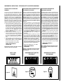

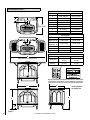
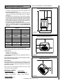
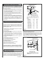
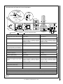

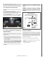

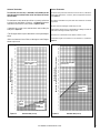
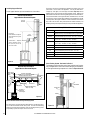

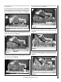
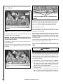


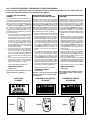
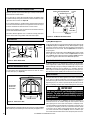

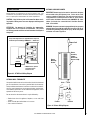
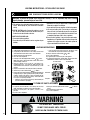


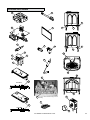
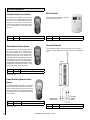
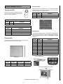
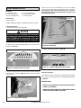


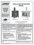
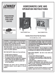

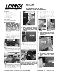
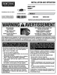

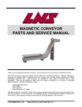
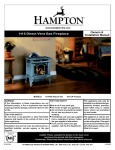

![000 CASORT [9].book](http://vs1.manualzilla.com/store/data/005753997_1-6c1117a0f29b8b2731a0aa33cfc5a43b-150x150.png)