1
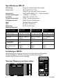
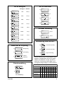
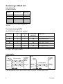
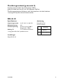
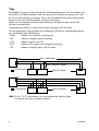
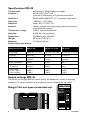
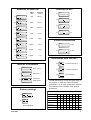
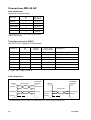
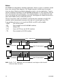
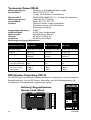
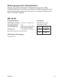
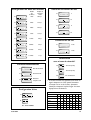
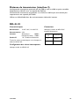
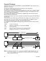
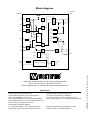
INSTALLATIONSANVISNING
INSTALLATION MANUAL
INSTALLATIONS ANLEITUNG
MANUEL D’INSTALLATION
6157-2002
Galvanic
Isolation
Transient
Protection
Balanced
Transmission
CE
Approved
Omvandlare RS-232 – RS-422/485
Converter RS-232 – RS-422/485
RS-232 – RS-422/485 Wandler
Convertisseur RS-232-RS-422/485
www.westermo.se
© Westermo Teleindustri AB • 2001 • REV. A
AC
5
4
D
M
LV
5
4
D
M
Specifikationer MD-45
Överföring
Gränssnitt 1
Asynkront, full/halv duplex eller simplex
EIA RS-232-C/ITU-T V.24
9-polig D-sub, hylsa eller 9-polig skruvplint
EIA RS-422/RS-485/ITU V.11, 5-polig skruvplint
1 200 bit/s – 115,2 kbit/s
Power, RD, CTS, RTS, TD
5–50°C, omgivningstemperatur
0–95% RH, utan kondensation
55x100x128 mm (BxHxD)
0,5 kg AC / 0,25 kg LV
På 35 mm DIN-skena
Gränssnitt 2
Överföringshastighet
Lysdioder
Temperaturområde
Fuktighetsområde
Mått
Vikt
Montering
Matningsalternativ
Modelbeteckning
MD-45 AC
MD-45 115 V AC
MD-45 LV
Strömförsörjning
230 V AC +15/–10%
115 V AC +15/–10%
12–45 V AC +15/–10%
Frekvens
48–62 Hz
48–62 Hz
12–60 V DC
Säkring, F1
100 mA S 5x20 mm
Littlefuse
100 mA S 5x20 mm
Littlefuse
1 A T 5x20 mm
Wickmann
Effektförbrukning
22 mA
44 mA
2W
Transientskydd
Matning/Linje
Ja/Ja
Ja/Ja
–/Ja
Isolation RMS
Strömförsörjning
Linje
3 000 V
1 500 V
3 000 V
1 500 V
3 000 V
1 500 V
Inställningar MD-45
MD-45 kan genom inställningar anpassas till ett flertal olika driftförhållanden.
Samtliga omkopplare i MD-45 är åtkomliga när lådans lock avlägsnas.
Locket avlägsnas med ett enkelt handgrepp.
PWR TD RD RTS CTS
Varning! Öppna ej ansluten enhet
DSR SG
V24/RS-232-C
CONNECTION
MD-45 LV
2
S1:1-8
1 2 3 4 5 6 7 8 9
S2:1-4
V24/RS-232-C
RS-422/RS-485/V11
CONVERTER
LINE CONNECTION
R+ R- T+ T1 2 3 4
5
POWER
–
+
6157-2002
Val av hastighet
Val av antal bitar
ON
Hastighet Vändtid
S1
9
1 2 3 4 5 6 7 8
ON
S1
1 200
780 µs
1 2 3 4 5 6 7 8
ON
S1
10
ON
1 2 3 4 5 6 7 8
S1
2 400
410 µs
1 2 3 4 5 6 7 8
ON
S1
ON
S1
4 800
11
1 2 3 4 5 6 7 8
220 µs
1 2 3 4 5 6 7 8
ON
S1
ON
S1
9 600
130 µs
19 200
48 µs
38 400
34 µs
12
1 2 3 4 5 6 7 8
1 2 3 4 5 6 7 8
ON
S1
2/4-tråds överföring
1 2 3 4 5 6 7 8
ON
S1
ON
S1
2-tråd
1 2 3 4 5 6 7 8
1 2 3 4 5 6 7 8
ON
S1
57 600
22 µs
ON
S1
1 2 3 4 5 6 7 8
4-tråd
1 2 3 4 5 6 7 8
ON
S1
115 200
11 µs
1 2 3 4 5 6 7 8
Terminering med fail-safe *
ON
S2
Data eller RTS-styrning
Terminerad (4-tråd)
1 2 3 4
ON
S1
ON
Datastyrning
S2
1 2 3 4 5 6 7 8
Terminerad (2-tråd)
1 2 3 4
ON
S1
RTS-styrning
ON
S2
1 2 3 4 5 6 7 8
Ingen terminering
1 2 3 4
ON
S1
1 2 3 4 5 6 7 8
Sändare
alltid aktiv
Fabriksinställning
* Fail-safe funktionen gör att mottagaren alltid
uppfattar signaltillståndet OFF då inkopplad
sändare har tillståndet tri-state (sändare ej
aktiverad). Terminering skall kopplas in på
mottagaren belägen längst bort från sändaren.
Hjälptabell för inställning av antal databitar
ON
7 bitar
1 2 3 4 5 6 7 8
8 bitar
S1
ON
S2
Ingen paritet
Paritet
1 2 3 4
1 stoppbit
S1: 8 används ej
2 stoppbitar
Antal bitar
6157-2002
• • • •
• • • •
• • • •
• • • •
•
• • •
•
• • •
9
10
10
10
11
11
11
12
3
Anslutningar MD-45 AC
Linjeanslutning
(5-polig skruvplint)
Anslutnings nr.
ITU-T V.11
Benämning
Mottagare
1
A’ (R+)
Mottagare
2
B’ (R–)
Sändare
3
A’ (T+)
Sändare
4
B’ (T–)
5
Skärm
Riktning
Definitionen R+/R–,T+/T– kan variera mellan olika
tillverkare.
Terminalanslutning (DCE)
(RS-232-C/V.24, 9-polig D-sub, hylsdon)
Riktning
Stift
nr.
Skruvplint
nr.
ITU-T V.24
Benämning
Beskrivning
I
3
8
103
TD / Transmitted Data
O
2
7
104
RD / Received Data
I
7
6
105
RTS / Request to Send
O
8
5
106
CTS / Clear to Send
O
6
2
107
DSR / Data Set Ready
–
5
9&1
102
SG / Signal Ground
O
1
4
109
DCD / Data Carrier Detect
I = ingång O = utgång på MD-45
Linjekoppling
4-tråd
MD-45
1
Mottagare A’
2
B’
3
Sändare
A
4
B
Skärm *) 5
2-tråd
RS-422/485
utrustning
Tvinnade trådpar
A
B’
RS-422/485
utrustning
Sändare
B
A’
MD-45
Mottagare
Tvinnade trådpar
Sändare/ 3
A/A’
A/A’
Mottagare
4
B/B’
B/B’
Skärm *) 5
Sändare/
Mottagare
*) Om skärmad kabel används, anslut skärmen endast i en ände för att undvika jordströmmar.
4
6157-2002
Överföringsavstånd (gränssnitt 2)
Använd partvinnad kabel. Max ledningslängd 1200 m
(gäller för kabel med area 0,3 mm2 och kapacitans 42pF/m)
Överföringsegenskaperna förbättras med sänkt kapacitans och ökad kabelarea.
I störningsrik miljö bör skärmad kabel användas.
MD-45 LV
Specifikationer
Anslutning
Inspänningsområde
Effektförbrukning
Isolationsspänning
Enligt MD-45 AC
förutom matning
12–45 V AC, 12–60 V DC
2W
Strömförsörjning 3 000 V,
linjegränssnitt 1 500 V
Säkring, F1
1 A T 5x20 mm Wickmann
I övrigt gäller MD-45 AC specifikationerna
Ansl.
nr.
Spänningsanslutning
1
– Spänning
2
+ Spänning
Inställningar
Enligt MD-45 AC
6157-2002
5
Tips
RS-422/485 är gränssnitt konstruerade för multidroppapplikationer. Då man kopplar upp
en RS-422 alt. RS-485 förbindelse skall man tänka på att installera ett bussnät, d v s det
får inte vara förgreningar på kablaget. För att få rätt kabelavslutning skall masteromvandlaren samt den sist anslutna enhetens mottagare termineras.
Nedan visas multidroppinstallation med terminering i RS-485 (2-tråds) och RS-422
(4-tråds) kommunikation.
Linjesändaren på MD-45 är endast aktiv då data mottages på RS-232 sidan.
Om det uppkommer något problem vid inkoppling av MD-45 kan lysdiodsindikeringarna
vara till värdefull hjälp vid felsökning.
• PWR:
Indikerar att enheten är spänningssatt.
• RD:
Indikerar mottagen data på linjesidan.
• CTS:
Indikerar samma som RTS.
• RTS:
Indikerar RTS signalen från inkopplad utrustning.
• TD:
Indikerar mottagen data på RS-232 sidan.
Max 1 200 meter
A
B
Max avstånd 0,3 meter
B A
B A
=Terminering
B A
Max 32 enheter
A’
B’
A
B
B’ A’ B A B’ A’ B A
=Terminering
B’ A’ B A
Max 32 enheter
OBS! R+/R–, T+/T– definitionerna är ej standardiserade, det kan hjälpa
att skifta A och B om ej enheten fungerar.
6
6157-2002
ANTECKNINGAR
.....................................................................................................................................................................................................................
.....................................................................................................................................................................................................................
.....................................................................................................................................................................................................................
.....................................................................................................................................................................................................................
.....................................................................................................................................................................................................................
.....................................................................................................................................................................................................................
.....................................................................................................................................................................................................................
.....................................................................................................................................................................................................................
.....................................................................................................................................................................................................................
.....................................................................................................................................................................................................................
.....................................................................................................................................................................................................................
.....................................................................................................................................................................................................................
.....................................................................................................................................................................................................................
.....................................................................................................................................................................................................................
.....................................................................................................................................................................................................................
6157-2002
7
Specifications MD-45
Transmission
Interface 1
Interface 2
Data rate
Indicators
Isolation
Temperature range
Humidity
Dimensions
Weight
Mounting
Power supply alternatives
Asynchronous, full/half duplex or simplex
EIA RS-232-C/ITU-T V.24
9-position D-sub female, or 9-position screw block
EIA RS-422/RS-485/ITU-T V.11, 5-position screw block
1 200 bit/s – 115.2 kbit/s
Power, RD, CTS, RTS, TD
Galvanic isolation with opto-coupler (data transmission)
and transformer (supply)
5–50°C, ambient temperature
0–95% RH, non-condensing
55x100x128 mm (WxHxD)
0.5 kg AC / 0.25 kg LV
On DIN-rail 35 mm
Model description
MD-45 AC
MD-45 115 V AC
MD-45 LV
Power supply
230 V AC +15/–10%
115 V AC +15/–10%
12–45 V AC +15/–10%
Frequency
48–62 Hz
48–62 Hz
12–60 V DC
Fuse, F1
100 mA F 5x20 mm
Littlefuse
100 mA F 5x20 mm
Littlefuse
1 A S 5x20 mm
Wickmann
Power consumption
44 mA
22 mA
2W
Transient protection
Power/Line
Yes/Yes
Yes/Yes
–/Yes
Isolation RMS
Power supply
Data interface
3 000 V
1 500 V
3 000 V
1 500 V
3 000 V
1 500 V
Switch settings MD-45
The MD-45 can through different switch settings be adapted to a variety of operating
conditions. To set the switches, open the plastic case by removing the top cover.
Danger! Do not open connected unit
PWR TD RD RTS CTS
DSR SG
V24/RS-232-C
CONNECTION
MD-45 LV
8
S1:1-8
1 2 3 4 5 6 7 8 9
S2:1-4
V24/RS-232-C
RS-422/RS-485/V11
CONVERTER
LINE CONNECTION
R+ R- T+ T1 2 3 4
5
POWER
–
+
6157-2002
Selection of bits
Selection of data rate
Data
rate
Turning
time
ON
S1
9
1 2 3 4 5 6 7 8
ON
S1
1 200
780 µs
1 2 3 4 5 6 7 8
ON
S1
10
ON
1 2 3 4 5 6 7 8
S1
2 400
410 µs
1 2 3 4 5 6 7 8
ON
S1
ON
S1
4 800
11
1 2 3 4 5 6 7 8
220 µs
1 2 3 4 5 6 7 8
ON
S1
ON
S1
9 600
130 µs
19 200
48 µs
38 400
34 µs
12
1 2 3 4 5 6 7 8
1 2 3 4 5 6 7 8
ON
S1
2/4-wire transmission
1 2 3 4 5 6 7 8
ON
S1
ON
S1
2-wire
1 2 3 4 5 6 7 8
1 2 3 4 5 6 7 8
ON
S1
57 600
22 µs
ON
S1
1 2 3 4 5 6 7 8
4-wire
1 2 3 4 5 6 7 8
ON
S1
115 200
11 µs
1 2 3 4 5 6 7 8
Termination with fail-safe *
ON
S2
Data or RTS-control
Terminated (4-wire)
1 2 3 4
ON
S1
ON
Data control
S2
1 2 3 4 5 6 7 8
Terminated (2-wire)
1 2 3 4
ON
S1
RTS-control
ON
S2
1 2 3 4 5 6 7 8
No termination
1 2 3 4
ON
S1
1 2 3 4 5 6 7 8
Transmitter
always active
Factory settings
* The fail-safe function forces the signal state of
the receiver to OFF when the connected
transmitter is in tri-state (transmitter inactive).
The receiver located furthest away shall be
terminated.
Supervision table when selecting data bits
ON
7 bits
1 2 3 4 5 6 7 8
8 bits
S1
ON
S2
No parity
Parity
1 2 3 4
1 stop bit
S1: 8 not used
2 stop bits
Number of bits
6157-2002
• • • •
• • • •
• • • •
• • • •
•
• • •
•
• • •
9
10
10
10
11
11
11
12
9
Connections MD-45 AC
Line connection
(5-position screw-terminal)
Direction
Pin
no.
ITU-T V.11
Description
Receiver
1
A’ (R+)
Receiver
2
B’ (R–)
Transmitter
3
A’ (T+)
Transmitter
4
B’ (T–)
5
Shield
The definitions R+/R–,T+/T– can be various between
different manufactures.
Terminal connection (DCE)
(RS-232-C/V.24, 9-position D-sub, female)
Direction
Pin
no.
Screwterminal
ITU-T V.24
Circuit number
I
3
8
103
TD / Transmitted Data
O
2
7
104
RD / Received Data
I
7
6
105
RTS / Request to Send
O
8
5
106
CTS / Clear to Send
O
6
2
107
DSR / Data Set Ready
–
5
9&1
102
SG / Signal Ground
O
1
4
109
DCD / Data Carrier Detect
I = input
Description
O = output on MD-45
Line connection
4-wire
2-wire
MD-45
Receiver
RS-422/485
equipment
Twisted pairs
1
A’
A
B’
3
Transmitter A
4
B
Shield *) 5
B
RS-422/485
equipment
MD-45
Transmitter
2
A’
B’
Twisted pairs
Receiver
3
Transmitter/ A/A’
Receiver 4
B/B’
Shield *) 5
A/A’ Transmitter/
Receiver
B/B’
*) If shielded cable is used, connect the shield only at one end to avoid ground currents.
10
6157-2002
Transmission range (interface 2)
Use twisted pair cable. Max transmission range 1200 m
(cable specifications 0.3 mm2 and capacitance 42pF/m).
The transmission range will increase if a cable with lower capacitance and larger
diameter is used.
Use shielded cable in heavy industrial environments.
MD-45 LV
Specifications
Connections
Power supply
Power consumption
Isolation
According to MD-45 AC,
except power supply
12–45 V AC, 12–60 V DC
2W
Power supply 3 000 V,
Data interface 1 500 V
Fuse, F1
1 A T 5x20 mm Wickmann
I övrigt gäller MD-45 AC specifikationerna
Connection
no.
Power
Supply
1
– Voltage
2
+ Voltage
Switch settings
According to MD-45 AC
6157-2002
11
Hints
RS-422/485 was designed for multidrop applications. When a system is installed it should
form a bus structure (see diagrams). Star shaped networks should never be created,
there are other Westermo products designed to work in star net applications. To get a
correct installation according to the RS-422/485 specification it´s very important that the
line is terminated at the correct points. The recommendation is to terminate the receiver on the master unit and the final bus slave unit. See diagrams for details of how this is
done with RS-485 (2-wire) and RS-422 (4-wire).
The line transmitter used in the MD-45 is activated by data received on the RS-232
interface, unlike conventional converters that rely on a control signal (e.g. RTS).
If any problems do occur on set up of the MD-45, the LED’s will be helpful.
• PWR:
The unit has power.
• RD:
Data received on the RS-422/485 interface.
• CTS:
Follows RTS.
• RTS:
Status of RTS from the RS-232 interface.
• TD:
Data received on RS-232 interface.
Max 1 200 metres
A
B
Max 0.3 metre
B A
B A
=Termination
B A
Max 32 connections
A’
B’
A
B
B’ A’ B A B’ A’ B A
=Termination
B’ A’ B A
Max 32 connections
N.B. R+/R–, T+/T– definitions are not standard, it can help to shift A and B
if the unit does not work.
12
6157-2002
OWN COMMENTS
.....................................................................................................................................................................................................................
.....................................................................................................................................................................................................................
.....................................................................................................................................................................................................................
.....................................................................................................................................................................................................................
.....................................................................................................................................................................................................................
.....................................................................................................................................................................................................................
.....................................................................................................................................................................................................................
.....................................................................................................................................................................................................................
.....................................................................................................................................................................................................................
.....................................................................................................................................................................................................................
.....................................................................................................................................................................................................................
.....................................................................................................................................................................................................................
.....................................................................................................................................................................................................................
.....................................................................................................................................................................................................................
.....................................................................................................................................................................................................................
6157-2002
13
Technische Daten MD-45
Übertragungsarten
Schnittstelle 1
Asynchron, Voll-/Halbduplex oder Simplex
EIA RS-232-C/ITU-T V.24
9 polige Sub-D-Buchse, Schraubklemme
Schnittstelle 2
EIA RS-422/RS-485/ITU-T V.11, 5-polige Schraubklemme
Übertragungsraten
1 200 Bit/s bis 115,2 Kbit/s
Leuchtdioden
Power, RD, CTS, RTS, TD
Isolation
Galvanisch Isoliert mittels Optokoppler
(Datenübertragung) und Transformator
(Spannungsversorgung)
Umgebungstemperatur
5–50°C
Luftfeuchtigkeit
0–95%, nicht kondensierend
Abmessungen
55x100x128 mm (BxHxT)
Gewicht
0,5 kg AC / 0,25 kg DC
Installation
auf 35 mm Din-Schiene
Spannungsversorgung Alternativen
Modellbezeichnung
MD-45 AC
MD-45 115 V AC
MD-45 LV
Stromversorgung
230 V AC +15/–10%
115 V AC +15/–10%
12–45 V AC +15/–10%
Frequenz
48–62 Hz
48–62 Hz
12–60 V DC
Sicherung F1
100 mA 5x20 mm
Littelfuse
100 mA 5x20 mm
Littelfuse
1 A 5x20 mm
Wickmann
Leistungsaufnahme
22 mA
44 mA
2W
Transientenschutz
Stromvers./Schnittst.
Ja/Ja
Ja/Ja
–/Ja
Isolation RMS
Stromversorgung
Schnittstelle
3 000 V
1 500 V
3 000 V
1 500 V
3 000 V
1 500 V
DIP-Schalter Einstellung MD-45
Das MD-45 bietet verschiedene Einstellmöglichkeiten zur Abstimmung auf verschiedenste
Betriebsverhälnisse. Um die DIP-Schalter einzustellen muß die Gehäuseabdeckung z.B.
mit Hilfe eines Schraubendrehers abgenommen werden.
Achtung! Angeschlossene
Geräte nicht öffnen
PWR TD RD RTS CTS
DSR SG
V24/RS-232-C
CONNECTION
MD-45 LV
14
S1:1-8
1 2 3 4 5 6 7 8 9
S2:1-4
V24/RS-232-C
RS-422/RS-485/V11
CONVERTER
LINE CONNECTION
R+ R- T+ T1 2 3 4
5
POWER
–
+
6157-2002
Anzahl der Datenbits
Übertragungsgeschwindigkeit
Übertragungsrate
Umschalt
-zeit
ON
S1
9
1 2 3 4 5 6 7 8
ON
S1
1 200
780 µs
1 2 3 4 5 6 7 8
ON
S1
10
ON
1 2 3 4 5 6 7 8
S1
2 400
410 µs
1 2 3 4 5 6 7 8
ON
S1
ON
S1
4 800
11
1 2 3 4 5 6 7 8
220 µs
1 2 3 4 5 6 7 8
ON
S1
ON
S1
9 600
130 µs
19 200
48 µs
38 400
34 µs
12
1 2 3 4 5 6 7 8
1 2 3 4 5 6 7 8
ON
S1
2/4-Draht Übertragung
1 2 3 4 5 6 7 8
ON
ON
S1
S1
2-Draht
1 2 3 4 5 6 7 8
1 2 3 4 5 6 7 8
ON
S1
57 600
ON
22 µs
S1
1 2 3 4 5 6 7 8
4-Draht
1 2 3 4 5 6 7 8
ON
S1
115 200
11 µs
1 2 3 4 5 6 7 8
Termination mit fail-safe *
ON
S2
Data oder RTS-Kontrol
4-Draht Termination
1 2 3 4
ON
S1
ON
S2
Datenfluß
2-Draht Termination
1 2 3 4 5 6 7 8
1 2 3 4
ON
S1
ON
RTS-Steuerung
S2
Keine Termination
1 2 3 4 5 6 7 8
ON
S1
1 2 3 4 5 6 7 8
1 2 3 4
Sender
immer aktiv
* Die fail-safe Funktion zwingt den Empfänger
in AUS-Zustand zu gehen, wenn der angeschlossene
Sender im Tri-State Zustand ist (Sender nicht aktiv).
Der am weitesten entfernteste Empfänger sollte terminiert werden.
Werkseinstellungen
Übersichtstabelle für Datenlänge
ON
7 Bits
1 2 3 4 5 6 7 8
8 Bits
S1
Keine Parität
ON
S2
Parität
1 2 3 4
S1: 8 nicht benutzt
1 Stop Bit
2 Stop Bit
Anzahl der Bits
6157-2002
• • • •
• • • •
• • • •
• • • •
•
• • •
•
• • •
9
10
10
10
11
11
11
12
15
MD-45 AC
Leitungsanschluß
(5-polige Schraubklemme)
Anschluß
Nr.
ITU-T V.11
Beschreibung
Empfänger
1
A’ (R+)
Empfänger
2
B’ (R–)
Sender
3
A’ (T+)
Sender
4
B’ (T–)
5
Schirmung
Richtung
Die Bezeichnungen R+/R–,T+/T– können abhängig
vom Hersteller variieren.
Terminalanschluß (DÜE)
(RS-232-c/V.24, 9-polige Sub-D Buchse)
Richtung
Pin
Nr.
Klemme
ITU-T V.24
Bezeichnung
Beschreibung
I
3
8
103
TD / Transmitted Data
O
2
7
104
RD / Received Data
I
7
6
105
RTS / Request to Send
O
8
5
106
CTS / Clear to Send
O
6
2
107
DSR / Data Set Ready
–
5
9&1
102
SG / Signal Ground
O
1
4
109
DCD / Data Carrier Detect
I = Eingang O = Ausgang des MD-45
Leitungsanschluß
4-Draht
2-Draht
MD-45
Empfänger
RS-422/485
Gerät
paarverseilte Leitung
1
A’
A
B’
B
RS-422/485
Gerät
MD-45
Sender
2
paarverseilte Leitung
3
Sender
4
Schirm *) 5
3
A
A’
B
B’
Empfänger
Sender/
A/A’
Empfänger 4
B/B’
Schirm *) 5
A/A’ Sender/
Empfänger
B/B’
*) Bei Verwendung von abgeschirmten Kabeln den Schirm nur auf einer Seite anschließen um Erdströme zu
vermeiden
16
6157-2002
Übertragungsweiten (Schnittstelle2)
Benutzen Sie paarverseilte Leitungen. Maximale Übertragungsweite 1 200 m.
(bei Kabelspezifikationen von 0,3 mm2 und 42 pF/m). Die Übertragungsweite nimmt
bei kleinerer Kapazität und größerem Durchmesser zu. Benutzen Sie abgeschirmte
Kabel in schlechter Umgebung.
MD-45 DC
Technische Daten
Anschlüsse
Spannungsversorgung 12–45 V AC, 12–60 V DC
Leistungsaufnahme
2W
Isolationsspannung
Spannungsversorgung 3 000 V
Datenschnittstelle 1500 V
Sicherung, F1
1 A T 5x20 mm Wickmann
Siehe MD-45 AC, außer
Spannungsversorgung
Anschluß
Nr.
Spannungsversorgung
1
– Pol
2
+ Pol
Alle anderen Merkmale siehe MD-45 AC
DIP-Schalter Einstellungen
Siehe MD-45 AC
6157-2002
17
Tips
Der Schnittstellenstandard RS-422/485 wurde für Mehrpunktverbindungen entwickelt.
Dieser Standard ist für Busnetze (siehe Beispiele) geeignet. Sternnetze sollten vermieden
werden. Für eine korrekte Installation eines RS-422/485 sollte an den richtigen Punkten
die Termination eingeschaltet werden. Es sollte am Empfänger des Masters und am letzten Slave die Termination eingeschaltet werden. Siehe Beispiele für RS-485 (2-Draht) und
RS-422 (4-Draht) Termination.
Der Sender des MD-45 wird aktiviert sobald Daten an der RS-232 Schnittstelle empfangen werden, nicht wie normale Konverter die ein Kontrollsignal z.B. RTS benötigen.
Bei Problemen mit der Einstellung des MD-42 können die LED´s hilfreich sein:
• PWR
Das Gerät hat Versorgungsspannung
• RD
Daten Empfang an der RS-422/485 Schnittstelle
• CTS
folgt RTS.
• RTS
zeigt den Status der RS-232 Schnittstelle an.
• TD
Daten Empfang an der RS-232 Schnittstelle
max. 1 200 Meter
A
B
max. 0,3 Meter
B A
B A
=Termination
B A
max. 32 Geräte
A’
B’
A
B
B’ A’ B A B’ A’ B A
=Termination
B’ A’ B A
max. 32 Geräte
Hinweis: Die Bezeichnungen R+/R-, T+/T- sind nicht Standard, es kann bei Problemen
helfen, A und B zu tauschen.
18
6157-2002
EIGENE KOMMENTARE
.....................................................................................................................................................................................................................
.....................................................................................................................................................................................................................
.....................................................................................................................................................................................................................
.....................................................................................................................................................................................................................
.....................................................................................................................................................................................................................
.....................................................................................................................................................................................................................
.....................................................................................................................................................................................................................
.....................................................................................................................................................................................................................
.....................................................................................................................................................................................................................
.....................................................................................................................................................................................................................
.....................................................................................................................................................................................................................
.....................................................................................................................................................................................................................
.....................................................................................................................................................................................................................
.....................................................................................................................................................................................................................
.....................................................................................................................................................................................................................
6157-2002
19
Spécifications MD-45
Transmission
Interface 1
Interface 2
Vitesse
Indicateurs LED
Isolation
Gamme température
Humidité
Dimensions
Poids
Fixation
Possibilités d’alimentation
Asynchrone, full/half duplex ou simplex
EIA RS-232-C/ITU-T V.24
Connecteur sub-D 9 points femelle, DCE ou
Bornier à vis 9 points.
EIA RS-422/RS-485/ITU-T V.11
Bornier à vis 5 points.
1 200 bit/sec – 115,2 kbit/s
Power, RD, CTS, RTS, TD
Isolation galvanique avec opto-coupleur (transmission de
données) et transformateur (alimentation)
5–50°C température ambiante
0–95% RH non condensé
55x100x128 mm (LxHxP)
0,5 kg AC, / 0,25 kg LV
Sur Rail DIN 35 mm
Référence Modèle
MD-45 AC
MD-45 115 V AC
MD-45 LV
Tension d’alimentation
230 V AC +15/–10%
115 V AC +15/–10%
12–45 V AC +15/–10%
Fréquence
48–62 Hz
48–62 Hz
12–60 V DC
Fusible, F1
100 mA F 5x20 mm
Littelfuse
100 mA F 5x20 mm
Littelfuse
1 A S 5x20 mm
Wickmann
Consommation
44 mA
22 mA
2W
Protection Surtension
Alimentation/Ligne
Oui/Oui
Oui/Oui
–/Oui
Isolation RMS :
Alimentation
Interface Donnée
3 000 V
1 500 V
3 000 V
1 500 V
3 000 V
1 500 V
Configuration des micro-interrupteurs du MD-45
Le MD-45 peut être adapté à différents environnements à l’aide de la configuration des
micro-interrupteurs. On accède aux micro-interrupteurs en enlevant le capot supérieur.
ATTENTION !
Ne pas ouvrir sous tension
PWR TD RD RTS CTS
DSR SG
V24/RS-232-C
CONNECTION
MD-45 LV
20
S1:1-8
1 2 3 4 5 6 7 8 9
S2:1-4
V24/RS-232-C
RS-422/RS-485/V11
CONVERTER
LINE CONNECTION
R+ R- T+ T1 2 3 4
5
POWER
–
+
6157-2002
Sélection du nombre de bits
Configuration du débit des données
Débit
des
données
Temps de
retournement
ON
S1
9
1 2 3 4 5 6 7 8
ON
S1
1 200
780 µs
1 2 3 4 5 6 7 8
ON
S1
10
ON
1 2 3 4 5 6 7 8
S1
2 400
410 µs
1 2 3 4 5 6 7 8
ON
S1
ON
S1
4 800
11
1 2 3 4 5 6 7 8
220 µs
1 2 3 4 5 6 7 8
ON
S1
ON
S1
9 600
130 µs
19 200
48 µs
38 400
34 µs
12
1 2 3 4 5 6 7 8
1 2 3 4 5 6 7 8
ON
S1
Transmission 2/4 Fils
1 2 3 4 5 6 7 8
ON
S1
ON
S1
2 fils
1 2 3 4 5 6 7 8
1 2 3 4 5 6 7 8
ON
S1
57 600
22 µs
ON
S1
1 2 3 4 5 6 7 8
4 fils
1 2 3 4 5 6 7 8
ON
S1
115 200
11 µs
1 2 3 4 5 6 7 8
Terminaison
avec niveau de sécurité*
Contrôle Retournement
ON
S2
Terminé (4 fils)
1 2 3 4
ON
S1
Flux de Données
ON
1 2 3 4 5 6 7 8
S2
Terminé (2 fils)
1 2 3 4
ON
S1
Contrôle RTS
ON
1 2 3 4 5 6 7 8
S2
No termination
1 2 3 4
ON
S1
1 2 3 4 5 6 7 8
Emetteur
toujours actif
Configuration Usine
* La fonction niveau de sécurité force l’état du
signal récepteur sur OFF quand l’émetteur
connecté est en mode 3 états, (émetteur
inactif).Le récepteur le plus éloigné doit être
équipé d’une terminaison.
Table de contrôle pour sélection du nombre de bits
ON
S1
7 Bits
1 2 3 4 5 6 7 8
8 Bits
ON
Pas de parité
S2
Parité
1 2 3 4
1 bit de stop
S1 : 8 non utilisés
2 bits de stop
Nombre de bits
6157-2002
• • • •
• • • •
• • • •
• • • •
•
• • •
• • •
•
9
10
10
10
11
11
11
12
21
Connexions MD-45 AC
Connexion Ligne
(Bornier à vis 5 points)
Direction
N°
ITU-T V.11
Description
Récepteur
1
A’ (R+)
Récepteur
2
B’ (R–)
Emetteur
3
A’ (T+)
Emetteur
4
B’ (T–)
5
Blindage
Les définitions R+/R–,T+/T– peuvent changer suivant
les constructeurs.
Connexion Terminal (DCE)
(RS-232-C/V.24, Connecteur sub-D 9 points femelle / bornier à vis)
Direction
point
N°
Bornier
à vis
ITU-T V.24
Circuit N°
Description
I
3
8
103
TD/Donnée transmise
O
2
7
104
RD/Donnée reçue
I
7
6
105
RTS/Request To Send
O
8
5
106
CTS/Clear To Send
O
6
2
107
DSR/Data Set Ready
–
5
9&1
102
SG/ Masse
O
1
4
109
DCD/Data Carrier Detect
I = Input (entrée) O = Output (sortie) sur le MD-45
Connexion Ligne
4-fils
2-fils
Récepteur
Equipement
RS-422/485
Paires torsadées
MD-45
1
A’
A
B’
B
Equipement
RS-485
MD-45
Emetteur
2
Paires torsadées
3
Emetteur
4
Blindage *) 5
A
A’
B
B’
Récepteur
Emetteur/ 3
A/A’
Récepteur 4
B/B’
Blindage *) 5
Emetteur/
A/A’
Récepteur
B/B’
*) Si on utilise un câble blindé, connecter le blindage uniquement à une extrémité afin d’éviter les retours de
courant de terre.
22
6157-2002
Distance de transmission (interface 2)
La distance de transmission maximale est de 1200 m avec un câble en paire torsadée.
(Spécifications câble 0.3 mm2 et capacité de 42pF/m).
La distance de transmission augmentera si on utilise un câble ayant une section plus
importante et une capacité plus faible.
Utiliser un câble blindé dans des environnements industriels intenses.
MD-45 LV
Caractéristiques
Connexions
Alimentation
12–45 V AC, 12–60 V DC
Consommation 2 W
Isolation
Alimentation :
3 000 V
Interface Données : 1 500 V
Fusible F1
1 A T 5x20 mm Wickmann
Toutes les autres caractéristiques sont identiques à
celles du MD-45 AC
Identiques à celles du MD-45 AC
excepté l’alimentation
Connexion Alimentation
N°
1
Tension –
2
Tension +
Configuration des micro-interrupteurs
Identique à celle du MD-45 AC
6157-2002
23
Conseils Pratiques
Le MD-45 utilise une interface RS-422/485. Le standard RS422/485 a été conçu pour des
applications multipoints.
Le réseau est installé sous la forme d’une structure bus (voir diagramme).
Les réseaux en forme d’étoile sont proscrits.
Il existe d’autres produits Westermo qui permettent de travailler avec un réseau en étoile.
Une installation correcte d’un réseau RS-422/485 doit toujours être équipée d’une terminaison sur les points correspondants.
Il est indispensable d’équiper de terminaisons le récepteur de l’unité maître ainsi que le
dernier esclave qui termine le bus.
Le diagramme ci-contre vous montre comment est réalisée une connexion RS-485 (2fils) et
RS-422 (4 fils)
La fonction émission utilisée dans le MD-45 peut être activée soit par détection du flux
de données reçu sur le port RS-232, soit par le contrôle RTS en modifiant le micro
interrupteur correspondant (voir page 3 contrôle retournement).
Si un problème survient pendant la configuration du MD-45, les LED de statut peuvent
vous aider.
• PWR:
L’unité est alimentée.
• RD:
Réception de données sur l’interface RS-422/485.
• CTS:
Suit le signal RTS.
• RTS:
Statut du signal RTS provenant de l’interface RS-232.
• TD:
Réception de données sur l’interface RS-232/V.24
Max 1200 mètres
A
B
0,3 mètre Max
B A
B A
=Terminaison
B A
32 connexions Max
A’
B’
A
B
B’ A’ B A B’ A’ B A
=Terminaison
B’ A’ B A
32 connexions Max
Nota : Les définitions R+/R-,T+/T- ne sont pas standard. On peut résoudre dans certains cas des problèmes de connexion en inversant les fils A et B si les équipements ne fonctionnent pas.
24
6157-2002
Vos Remarques
.....................................................................................................................................................................................................................
.....................................................................................................................................................................................................................
.....................................................................................................................................................................................................................
.....................................................................................................................................................................................................................
.....................................................................................................................................................................................................................
.....................................................................................................................................................................................................................
.....................................................................................................................................................................................................................
.....................................................................................................................................................................................................................
.....................................................................................................................................................................................................................
.....................................................................................................................................................................................................................
.....................................................................................................................................................................................................................
.....................................................................................................................................................................................................................
.....................................................................................................................................................................................................................
.....................................................................................................................................................................................................................
.....................................................................................................................................................................................................................
6157-2002
25
Block diagram
V.11/RS-422
RS-485
V.24/RS-232
TD LED
TD
3
3
RTS LED
4
S2:4
7
RTS
A
B
S2:3
CTS
LED
CTS
+5V
8
B
Bus termination
0V
B
MCU
DSR
6
+5V
B
Bus termination
+5V
S2:2
0V
B
RD
LED
S2:1
RD
SG
2
5
S1:6
1
0VA
2
+5VA
0VB
5
A'
B'
Shield
0VA
+5V
B
Insulated power supply
0VB
Westermo Teleindustri AB • SE-640 40 Stora Sundby, Sweden
Phone +46 16 42 80 00 Fax +46 16 42 80 01
E-mail: [email protected] • Westermo Web site: www.westermo.se
Subsidiaries
Westermo Data Communications Ltd
Unit 14 Talisman Business Centre • Duncan Road
Park Gate, Southampton • SO31 7GA
Phone: +44(0)1489 580 585 • Fax.:+44(0)1489 580586
E-Mail: [email protected] • Web: www.westermo.co.uk
Westermo Data Communications GmbH
Goethestraße 67, 68753 Waghäusel
Tel.: +49(0)7254-95400-0 • Fax.:+49(0)7254-95400-9
E-Mail: [email protected] • Web: www.westermo.de
Westermo Data Communications S.A.R.L.
9 Chemin de Chilly 91160 CHAMPLAN
Tél : +33 1 69 10 21 00 • Fax : +33 1 69 10 21 01
E-mail : [email protected] • Site WEB: www.westermo.fr
Westermo Teleindustri AB have distributors in several
countries, contact us for further information.
02-11 Eskilstuna Offset AB, Eskilstuna, Sweden
F1
6157-2002
Power
supply