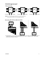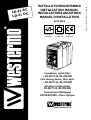
1
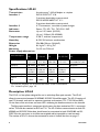
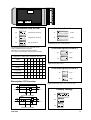
6072-2004
Galvanic
Isolation
Transient
Protection
CE
Approved
Linjedelare, optisk fiber
– RS-232/V.24, RS-422/485
Line sharing device, fibre optic
– RS-232/V.24, RS-422/485
Glasfaser Leitungsteiler
RS-232/V.24, RS-422/485
Convertisseur Multipoint
RS232/422/485 – Fibre Optique
www.westermo.se
© Westermo Teleindustri AB • 2000 • Rev. A
AC
3
6
D
L
C
D
3
6
LD
INSTALLATIONSANVISNING
INSTALLATION MANUAL
INSTALLATIONS ANLEITUNG
MANUEL D’INSTALLATION
Specifikationer LD-63
Överföring
Gränssnitt 1
Gränssnitt 2
Överföringshastighet
Lysdioder
Temperaturområde
Fuktighetsområde
Mått
Vikt
Montering
Matningsalternativ
Asynkront*, full/halv duplex eller simplex
EIA RS-232/ITU-T V.24
9-polig frånskiljbar skruvplint
EIA RS-422/RS-485/ ITU-T V.11
5-polig frånskiljbar skruvplint
4 ST-kontakter, se tabell för effektbudget
Upp till 115,2 kbit/s (RS-232)
Upp till 1,5 Mbit/s (RS-422/485)
Power, TD, RD, TX1, TX2, RX1, RX2
5–50°C, omgivningstemperatur
0–95% RH utan kondensation
55x100x128 mm (BxHxD)
0,6 kg AC / 0,3 kg DC
På 35 mm DIN-skena
LD-63
AC
LD-63
115V AC
LD-63
DC
LD-63
36–55V DC
LD-63
HV
Strömförsörjning
230V AC
+15/–10%
115V AC
+15/–10%
24V DC
+50/–50%
48V DC
+15/–25%
95–240 V AC±10%
110–240 V AC±10%
Frekvens
48–62Hz
48–62Hz
–
–
48–62Hz / –
Säkring, F2
100mA S
5x20 mm
Littelfuse
100mA S
5x20 mm
Littelfuse
1,6A S
5x20 mm
Littelfuse
1,6A S
5x20 mm
Littelfuse
1A T Wickmann
Effektförbrukning
20mA
40mA
3W
3W
40mA
Isolationsspänning
RMS
3 000V
3 000V
1 500V
1 500V
3 750V
Modellbeteckning
* Synkront protokoll kan överföras under vissa förutsättningar.
Se beskrivning ”Val av antal bitar” sid 4.
Funktionsbeskrivning LD-63
LD-63 är en linjedelare som möjliggör att bygga upp ett multidropp-nät via fiber där den
anslutna utrustningen antingen kan ha RS-422/485 eller RS-232/V.24 .
Modemet består av 2 fiberkanaler med en sändare respektive mottagare för vardera
kanalen TX1, TX2, RX1 och RX2. På frontpanelen finns dessutom 7 st lysdioder som ger
indikering av datatrafiken på kanalerna. De båda fiberkanalernas ingångar är transparanta
vilket betyder att inkommande data på RX1 ej kodas av utan sänds vidare av TX2 och
inkommande data på RX2 sänds vidare av TX1. LD-63 gör det möjligt att sända och ta
emot RS422/485 och RS-232/V.24, men inkommande data på gränssnitten kommer att
överlagras om data sänds samtidigt till gränssnitt RS-232/V.24 och RS-422/485.
Antalet LD-63 som kan seriekopplas är begränsat. Se tabell sid 4.
2
6072-2004
Effektbudget
Min. budget
Typ. budget
Enhet
Enhet
Fiber
820 nm
1300 nm
50/125
62,5/125
100/140
9/125
10,7 dB
14,5 dB
20,6 dB
8,1 dB
11,6 dB
singelmod
Fiber
820 nm
16,6 dB
18,6 dB
25,9 dB
6,3 dB
50/125
62,5/125
100/140
9/125
1300 nm singelmod
14,6 dB
15,1 dB
12,3 dB
”Min. budget” anger garanterat minsta effektbudget. Erfarenheten visar dock att värdet oftast ligger i
nivå med angivet ”Typ. budget”.
Förluster i fiberoptisk kabel
Nedan angivna värden kan variera beroende på kvalité och fabrikat på den fiberoptiska
kabeln.
Fiber
50/125 µm
62,5/125 µm
100/140 µm
9/125 µm
Dämpning
vid 820 nm
Dämpning
vid 1300 nm
3,0 dB/km
3,5 dB/km
4,0 dB/km
1,0 dB/km
1,2 dB/km
Dämpning
vid singelmod (1300 nm)
0,5 dB/km
Förluster i kontakter
Förluster i skarv
0,2–0,4 dB
Svetsad
0,1 dB
Mekanisk
0,2 dB
6072-2004
3
Inställningar LD-63
Val av V eller Y funktion
Överföringshastighet/Vändtid/
Antal enheter i serie
ON
Y
S1
1 2 3 4 5 6 7 8 9
ON
V
S1
1 2 3 4 5 6 7 8 9
Vändtid
Överföringshastighet
Antal*
enheter
0,4 ms
2 400 bit/s
20
0,2 ms
4 800 bit/s
20
0,1 ms
9 600 bit/s
20
75 µs
14 400 bit/s
20
50 µs
19 200 bit/s
20
37 µs
28 800 bit/s
20
25 µs
38 400 bit/s
20
16 µs
62 500 bit/s
20
11 µs
93 750 bit/s
20
9 µs
115,2 kbit/s
15
6 µs
187,5 kbit/s
10
3 µs
375 kbit/s
5
2 µs
500 kbit/s
20
1 µs
1,0 Mbit/s
10
0,7 µs
1,5 Mbit/s
4
ON
S1
1 2 3 4 5 6 7 8 9
V-funktion respektive Y-funktion enligt bild sid 5.
ON
S1
1 2 3 4 5 6 7 8 9
Val av retiming funktion
ON
S1
1 2 3 4 5 6 7 8 9
ON
Retiming
S1
1 2 3 4 5 6 7 8 9
ON
S1
1 2 3 4 5 6 7 8 9
ON
Retiming av
S1
1 2 3 4 5 6 7 8 9
ON
S1
1 2 3 4 5 6 7 8 9
Retiming funktionen beräknar exakt bitlängd
utgående från inställd hastighet och återskapar
därifrån signalen vilket gör att fler enheter kan
kopplas i serie. Retiming fungerar endast för
angivna hastigheter. För ej angivna hastigheter
( t ex 1,2 Mbit/s) ska retiming inte användas.
ON
S1
1 2 3 4 5 6 7 8 9
ON
S1
1 2 3 4 5 6 7 8 9
ON
S1
Val av antal bitar
1 2 3 4 5 6 7 8 9
ON
ON
9
S1
S1
1 2 3 4 5 6 7 8 9
1 2 3 4 5 6 7 8 9
ON
ON
10
S1
S1
1 2 3 4 5 6 7 8 9
1 2 3 4 5 6 7 8 9
ON
ON
11
S1
S1
1 2 3 4 5 6 7 8 9
1 2 3 4 5 6 7 8 9
ON
ON
*
S1
S1
1 2 3 4 5 6 7 8 9
1 2 3 4 5 6 7 8 9
ON
*) Använd denna inställning för synkrona
protokoll. Sändaren är aktiv fr o m
första databiten till 10 bittider efter
den sista höga databiten (se exempel
nedan). Hastigheten ställs till ≅10 ggr
den önskade kommunikationshastigheten.
S1
1 2 3 4 5 6 7 8 9
ON
S1
1 2 3 4 5 6 7 8 9
ON
S1
1 2 3 4 5 6 7 8 9
Exempel 19 200 bit/s
Startbit
Överföringshastighet 19 200
1 bit: 1/19 200 = 52µs
↵
1 bit = 52µs
Sändare aktiv
10x52µs = 520µs
Ställ hastigheten till 187,5 kbit/s
4
*) För ett större
antal enheter
kontakta Westermo
Möjlig
retiming
Vid användande av RS-232 är det inte nödvändigt att
konfigurera antal bitar samt överföringshastighet.
RS-232 gränssnittet kan hantera överföringshastigheter
från 0 upp till 115,2 kbit/s.
6072-2004
1 2 3 4 5 6 7 8 9
S3:4-1
S1:1-9
S2:1-5
Terminering med fail-safe
Val av 2- eller 4-tråd
ON
ON
Terminerad (2-tråd)
S2
4-tråd
S1
1 2 3 4 5 6 7 8 9
1 2 3 4 5
ON
ON
Terminerad (4-tråd)
S2
2-tråd
S1
1 2 3 4 5 6 7 8 9
1 2 3 4 5
ON
Ingen terminering
S2
1 2 3 4 5
Val av 2-tråd RS-485 eller 4-tråd RS-422.
Vid RS-232/V.24 används inte S1:1.
Fail-safe funktionen gör att mottagaren alltid uppfattar
signaltillståndet OFF då inkopplad sändare har tillståndet
tri-state (sändare ej aktiverad).
Terminering skall kopplas in på mottagaren belägen längst
bort från sändaren.
Uteffekt kanal 1
ON
1 2 3 4 5
ON
Översiktstabell vid val av databitar
• • •
7 bitar
8 bitar
Ingen paritet
Paritet
1 stopp bit
2 stopp bitar
Antal bitar
•
•
•
• •
• •
•
•
•
•
•
• •
•
•
• •
Låg
S2
Hög
S2
1 2 3 4 5
Normalt används hög uteffekt. Låg uteffekt används vid
fiberlängder under 100 meter.
Uteffekt kanal 2
ON
Låg
S3
1 2 3 4
ON
9 10 10 10 11 11 11
Hög
S3
1 2 3 4
Beskrivning V/Y-funktion
Normalt används hög uteffekt. Låg uteffekt används vid
fiberlängder under 100 meter. S3: 2–4 används ej.
LA-01
V
V-funktion
F/O
F/O
OR
kanal 1
Fabriksinställning
kanal 2
ON
S1
RS-232/V.24 / RS-422/485
1 2 3 4 5 6 7 8 9
LA-01
Y
Y-funktion
F/O
kanal 1
OR
OR
OR
F/O
ON
S2
1 2 3 4 5
kanal 2
ON
S3
RS-232/V.24 / RS-422/485
6072-2004
1 2 3 4
5
Anslutningar LD-63
Linjeanslutning
(5-polig skruvplint)
Riktning
PWR TD RD
Anslutnings
nr.
LD-63
ITU-T V.11
Benämning
Mottagare
1
A’ (R+)
Mottagare
2
B’ (R–)
Sändare
3
A (T+)
Sändare
4
B (T–)
5
Skärm
Rx1
Rx2
Tx1
Tx2
RS-422/485
R+ R- T+
1 2 3
T4
POWER
5
N
L
Definitionen R+/R–,T+/T– kan variera mellan olika
tillverkare.
Terminalanslutning (DCE)
(RS-232-C/V.24, 9-polig skruvplint)
Riktning
Skruvplint
nr.
ITU-T V.24
Benämning
Beskrivning
I
8
103
TD/Transmitted Data
O
7
104
RD/Received Data
–
9
102
SG/Signal Ground
I = Ingång O = Utgång på LD-63
Matningsanslutning
LD-63 AC
(3-polig skruvplint)
Anslutningsnr.
Spänningsanslutning
L
N
115*/230V
AC matning
Matningsanslutning
LD-63 DC
(2-polig skruvplint)
Anslutnings- Spänningsnr.
anslutning
1
– Spänning
2
+ Spänning
Matningsanslutning
LD-63 HV
(3-polig skruvplint)
Anslutningsnr.
Spänningsanslutning
L
N
+ Spänning
– Spänning
Skyddsjord
Skyddsjord
* LD-63 115V
Lysdiodindikeringar LD-63
•
•
•
•
•
•
•
6
PWR:Indikerar
TD: Indikerar
RD: Indikerar
Rx1: Indikerar
Rx2: Indikerar
Tx1: Indikerar
Tx2: Indikerar
att enheten är spänningssatt.
mottagen data på RS-232/V.24, RS-485 sidan.
sänd data på RS-232/V.24, RS-485 sidan.
mottagen data på fiberkanal 1.
mottagen data på fiberkanal 2.
sänd data på fiberkanal 1 från RS-232/V.24, RS-485 sidan.
sänd data på fiberkanal 2 från RS-232/V.24, RS-485 sidan.
6072-2004
Anslutningsexempel
Fiberanslutning
RX1
RX2
RX1
LD-63
TX1
RX1
LD-63
TX2
RS-232/V.24 eller
RX2
RS-422/485
RS-232/V.24
LD-63
TX2
TX1
eller
RX2
TX2
TX1
RS-422/485
RS-232/V.24
eller
RS-422/485
OBS! När en multidroppslinga avslutas med en LD-63 och fiberparet
ansluts på kanal 2 måste S1:2 stå i läge ON (Y-funktion)
Anslutning RS-232/V.24, RS-422, RS-485
RS-232/V.24
utrustning
SG TD RD
Rx2
Tx1
Tx1
Tx2
RS-422/485
R+ R- T+
1 2 3
PWR TD RD
C
Rx2
E
Ch1
C
T4
Tx2
POWER
5
N
RS-422/485
L
R+ R- T+
1 2 3
T4
POWER
5
N
L
E
Ch2
OPTO LINK MONITOR
LD-64
Rx1
Rx2
T+ T– R+ R–
RS-422
utrustning
*
T+ T–
RS-485
utrustning
*
*) Benämningarna T+, T–, R+, R– är inte standardiserade och kan variera mellan olika tillverkare. Första steget vid
felsökning bör alltid vara att skifta respektive kabelpar (byt T+ med T– och/eller R+ med R–. Observera att
kablarna endast ska skiftas i ena änden.
6072-2004
7
Specifications LD-63
Transmission
Interface 1
Interface 2
Indicators
Data rates
Temperature range
Humidity
Dimension
Weight
Mounting
Power supply alternatives
Asynchronous*, full/half duplex or simplex
EIA RS-232/ITU-T V.24
9-position detachable screw-terminal
EIA RS-422/RS-485/ITU-T V.11
5-position detachable screw-terminal
4 ST-connectors, see table of power budget
Power, TD, RD, TX1, TX2, RX1, RX2
Up to 115,2 kbit/s (RS-232)
Up to 1.5 Mbit/s (RS-422/485)
5–50°C, ambient temperature
0–95% RH without condensation
55x100x128 mm (WxHxD)
0.6 kg AC / 0.3 kg DC
On 35 mm DIN-rail
LD-63
AC
LD-63
115V AC
LD-63
DC
LD-63
36–55V DC
LD-63
HV
Power supply
230V AC
+15/–10%
115V AC
+15/–10%
24V DC
+50/–50%
48V DC
+15/–25%
95–240V AC±10%
110–240V DC±10%
Frequency
48–62Hz
48–62Hz
–
–
48–62Hz / –
Fuse, F2
100mA S
5x20 mm
Littelfuse
100mA S
5x20 mm
Littelfuse
1.6A S
5x20 mm
Littelfuse
1.6A S
5x20 mm
Littelfuse
1A T Wickmann
Power consumption
20mA
40mA
3W
3W
40mA
Isolation
RMS
3 000V
3 000V
1 500V
1 500V
3 750V
Model description
* Synchronous protocols can be transmitted under certain circumstances.
See ”selection of bits” page 10.
Description LD-63
The LD-63 is a line splitter designed for use in multi-drop fibre optic neworks. The LD-63
allows the conversion between RS-422/485, RS-232/V.24 and fibre optic. The LD-63 consists of
two F/O channels, each with its separate transmitter and receiver (TX1, TX2, RX1and RX2)
On the front of the unit there are seven LED’s indicating the datatransmission on the channels.
The fibre optic interface is transparent which means that data received on RX1 is retransmitted on TX2 and data received on RX2 on TX1. The LD-63 allows communication on both RS422/485 and RS-232/V.24 but data should never be transmitted to both RS-422/485 and RS232/V.24 at the same time as it will be oversampled and be impossible to read correctly.
The number of LD-63’s that can be connected in series is limited. See chart on page 11.
8
6072-2004
Power budget
Min. budget
Typ. budget
Unit
Unit
Fibre
820 nm
1300 nm
50/125
62.5/125
100/140
9/125
10.7 dB
14.5 dB
20.6 dB
8.1 dB
11.6 dB
single mode
Fibre
820 nm
1300 nm
16.6 dB
18.6 dB
25.9 dB
14.6 dB
15.1 dB
6.3 dB
50/125
62.5/125
100/140
9/125
single mode
12.3 dB
”Min. budget” states the minimum guaranteed power budget. Experience shows however that the
typical value is in the range of the indicated ”Typ. budget”.
Attenuation in fibre cable
The values below can differ depending on quality and manufacturer of the fibre-optic
cable.
Fibre
50/125 µm
62.5/125 µm
100/140 µm
9/125 µm
Attenuation
at 820 nm
Attenuation
at 1300 nm
3.0 dB/km
3.5 dB/km
4.0 dB/km
1.0 dB/km
1.2 dB/km
Attenuation
at single mode (1300 nm)
0.5 dB/km
Attenuation in connectors
Attenuation in splice
0.2–0.4 dB
Fusion
0.1 dB
Mechanical
0.2 dB
6072-2004
9
Switch settings LD-63
Selection of V or Y function
Turning/Transmission/
Number of units connected in serie
ON
Y
S1
Turning- Transmission Number*
time
rate
of units
1 2 3 4 5 6 7 8 9
ON
V
S1
ON
1 2 3 4 5 6 7 8 9
S1
V-function and Y-function are described
on page 11.
S1
0.4 ms
2 400 bit/s
20
0.2 ms
4 800 bit/s
20
0.1 ms
9 600 bit/s
20
75 µs
14 400 bit/s
20
50 µs
19 200 bit/s
20
37 µs
28 800 bit/s
20
25 µs
38 400 bit/s
20
16 µs
62 500 bit/s
20
11 µs
93 750 bit/s
20
9 µs
115.2 kbit/s
15
6 µs
187.5 kbit/s
10
3 µs
375 kbit/s
5
2 µs
500 kbit/s
20
1 µs
1.0 Mbit/s
10
0,7 µs
1.5 Mbit/s
4
1 2 3 4 5 6 7 8 9
ON
1 2 3 4 5 6 7 8 9
Selection of retiming function
ON
S1
1 2 3 4 5 6 7 8 9
ON
Retiming
S1
1 2 3 4 5 6 7 8 9
ON
S1
1 2 3 4 5 6 7 8 9
ON
Retiming of
S1
1 2 3 4 5 6 7 8 9
ON
S1
1 2 3 4 5 6 7 8 9
The retiming function calculates the exact bitlength based on the speed set and recreates
the signal. This allows for more units in series.
The retiming works only for the indicated
speeds. For other speeds (e g 1.2 Mbit/s)
retiming can not be used.
ON
S1
1 2 3 4 5 6 7 8 9
ON
S1
1 2 3 4 5 6 7 8 9
ON
Selection of bits
S1
1 2 3 4 5 6 7 8 9
ON
9
S1
1 2 3 4 5 6 7 8 9
ON
S1
1 2 3 4 5 6 7 8 9
ON
10
S1
1 2 3 4 5 6 7 8 9
ON
S1
1 2 3 4 5 6 7 8 9
ON
11
S1
1 2 3 4 5 6 7 8 9
ON
S1
1 2 3 4 5 6 7 8 9
ON
ON
*
S1
S1
1 2 3 4 5 6 7 8 9
1 2 3 4 5 6 7 8 9
*) Use this setting for synchronous
protocols.
The transmitter will be active from the
start bit to 10 bit-times after the last
high databit
(see example below).
The speed shall be set to ≅10 times
the required communication speed.
ON
S1
1 2 3 4 5 6 7 8 9
ON
S1
1 2 3 4 5 6 7 8 9
ON
S1
1 2 3 4 5 6 7 8 9
Example 19 200 bit/s
Start bit
Data rate 19 200
1 bit: 1/19 200 = 52µs
↵
1 bit = 52µs
Transmitter active
10x52µs = 520µs
Set the speed to 187.5 kbit/s
10
*) For additional units
please contact
Westermo
Retiming
possible
When using RS-232 interface it is not necessary to
select number of bits and transmission rate. The RS-232
interface can handle transmission rates from 0 up to
115.2 kbit/s.
6072-2004
1 2 3 4 5 6 7 8 9
S3:4-1
S1:1-9
S2:1-5
Termination with fail-safe
Selection of 2- or 4-wire
ON
Termination (2-wire)
S2
ON
1 2 3 4 5
1 2 3 4 5 6 7 8 9
ON
Termination (4-wire)
S2
ON
2-wire
S1
1 2 3 4 5
1 2 3 4 5 6 7 8 9
ON
No termination
S2
4-wire
S1
1 2 3 4 5
The fail-safe function forces the signal state of the
receiver to OFF when the connected
transmitter is in tri-state (transmitter inactive).
The receiver located furthest away shall be terminated.
Selection of 2-wire RS-485 or 4-wire RS-422.
For RS-232/V.24 S1:1 can be ignored.
Transmitted power channel 1
ON
Low
S2
1 2 3 4 5
Supervision table when selecting data bits
• • •
7 bits
•
•
•
• •
• •
•
•
•
•
•
• •
•
•
• •
8 bits
No parity
Parity
1 stop bit
2 stop bits
ON
High
S2
1 2 3 4 5
Normally high power is used. Low power is used with fibre
lengths shorter than 100 m.
Transmitted power channel 2
ON
Low
S3
1 2 3 4
Number of bits 9 10 10 10 11 11 11
ON
High
S3
1 2 3 4
Description V/Y-function
Normally high power is used. Low power is used with fibre
lengths shorter than 100 m. S3: 2–4 is not used.
LA-01
V
V-function
F/O
F/O
OR
channel 1
Factory settings
channel 2
ON
S1
RS-232/V.24 / RS-422/485
1 2 3 4 5 6 7 8 9
LA-01
Y
Y-function
F/O
channel 1
OR
OR
OR
F/O
ON
S2
1 2 3 4 5
channel 2
ON
S3
RS-232/V.24 / RS-422/485
6072-2004
1 2 3 4
11
Connections LD-63
Line connection
(5-position screw-terminal)
Direction
PWR TD RD
Connection
no.
ITU-T V.11
Description
Receiver
1
A’ (R+)
Receiver
2
B’ (R–)
Transmitter
3
A (T+)
Transmitter
4
B (T–)
5
LD-63
Rx1
Rx2
Tx1
Tx2
RS-422/485
R+ R- T+
1 2 3
Shield
T4
POWER
5
N
L
The definations R+/R–,T+/T– can be various between
different manufactures.
Terminal connection (DCE)
(RS-232-C/V.24, 9-position screw-terminal)
Direction
Screw
no.
ITU-T V.24
Description
I
8
103
TD/Transmitted Data
O
7
104
RD/Received Data
–
9
102
SG/Signal Ground
I = Input
Description
O = Output on LD-63
Power connection
LD-63 AC
Power connection
LD-63 DC
(3-position screw-terminal)
(2-position screw-terminal) (3-position screw-terminal)
Power connection
LD-63 HV
Connection
no.
Power
supply
Connection
no.
Power
supply
Connection
no.
Power
supply
L
N
115*/230V
AC power
1
– Voltage
2
+ Voltage
L
N
+ Voltage
– Voltage
PE/ Protective Earth
PE/ Protective Earth
* LD-63 115V
LEDs for indication on LD-63
•
•
•
•
•
•
•
PWR: Indicates that the converter has power.
TD: Indicates that the converter is receiving data on RS-232/V.24, RS-485 side.
RD: Indicates that the converter is sending data on RS-232/V.24, RS-485 side.
Rx1: Indicates received data on fiber channel 1.
Rx2: Indicates received data on fiber channel 2.
Tx1: Indicates that the converter is sending data on fiber channel 1 from RS-232/V.24, RS-485 side.
Tx2: Indicates that the converter is sending data on fiber channel 2 from RS-232/V.24, RS-485 side.
12
6072-2004
How to connect
Fibre optic connection
RX1
RX2
RX1
LD-63
RS-232/V.24
or
RX1
LD-63
TX2
TX1
RX2
TX1
RS-232/V.24
RS-422/485
LD-63
TX2
or
RX2
TX2
TX1
RS-232/V.24
RS-422/485
or
RS-422/485
NB When a multidrop connection ends with an LD-63 and the fibre pair is
connected on channel 2, the switch S1:2 must be set (Y-mode)
Connection of RS-232/V.24, RS-422, RS-485
RS-232/V.24
equipment
SG TD RD
Rx2
Tx1
Tx1
Tx2
RS-422/485
R+ R- T+
1 2 3
PWR TD RD
C
Rx2
E
Ch1
C
T4
Tx2
POWER
5
N
RS-422/485
L
R+ R- T+
1 2 3
T4
POWER
5
N
L
E
Ch2
OPTO LINK MONITOR
LD-64
Rx1
Rx2
T+ T– R+ R–
RS-422
equipment
*
T+ T–
RS-485
equipment
*
*) The designations T+, T–, R+, R– are not standardised and may vary between different manufactures. The first
step in fault finding is to reverse the cables (swap T+ with T– and/or R+ with R–). Please note that this should
be done only at one end!
6072-2004
13
Technische Daten LD-63
Asynchron*, Voll-/Halbduplex oder Simplex
EIA RS-232-C/ITU-T V.24
9 polige Schraubklemme
EIA RS-422/RS-485/ITU-T V.11
5 polige Schraubklemme
Schnittstelle 2
4 ST-Anschlüsse, siehe Tabelle Dämpfung
Leuchtdioden
Betrieb, TD, RD, TX1, TX2, RX1, RX2
Übertragungsraten
bis zu 115,2 kbit/s (RS-232)
bis zu 1,5 Mbit/s (RS-422/485)
Umgebungstemperatur
5–50°C
Luftfeuchtigkeit
0–95%, nicht kondensierend
Abmessungen
55x100x128 mm (BxHxT)
Gewicht
0,6 Kg AC / 0,3 Kg DC
Installation
auf 35 mm Din Schiene
Spannungsversorgung Alternativen
Übertragungsarten
Schnittstelle 1
Modell Bezeichnung
LD-63
AC
LD-63
AC 115V
LD-63
DC
LD-63
LD-63
36–55V DC HV
Spannungsversorgung
230V AC
+15/–10%
115V AC
+15/–10%
24V DC
+50/–50%
48V DC
+15/–25%
95–240V AC±10%
110–240V DC±10%
Frequenz
48–62Hz
48–62Hz
–
–
48–62Hz / –
Sicherung, F2
100mA S
5x20 mm
Littelfuse
100mA S
5x20 mm
Littelfuse
1,6A S
5x20 mm
Littelfuse
1,6A S
5x20 mm
Littelfuse
1A T Wickmann
Leistungsaufnahme
20mA
40mA
3W
3W
40mA
Isolationsspannung
RMS
3 000V
3 000V
1 500V
1 500V
3 750V
* Synchrone Protokolle können unter bestimmten Umständen übertragen werden.
Siehe ”Anzahl der Bits” Seite 16.
Beschreibung LD-63
Das LD-63 ist ein Leitungsteiler der für Multidrop Glasfasernetze entwickelt wurde. Er
erlaubt die Umsetzung zwischen RS-422/485, RS-232/V.24 und Glasfaser. Das LD-63 hat 2
Glasfaser Kanäle, jeder mit separater Sende- und Empfangseinheit (TX1,TX2, RX1 und RX2).
Auf der Frontplatte sind sieben LED’s zur Überwachung der Datenübertragung angebracht.
Die Glasfaserschnittstelle ist transparent, somit werden Daten die an RX1 empfangen werden an TX2 ausgegeben, und Daten von RX2 an TX1. Das LD-63 ermöglicht die
Kommunikation mit RS-232/V.24 genauso wie mit RS-422/485, aber die Daten können nie
gleichzeitig an beide Schnittstellen übertragen werden. Dies würde zu
Datenverstümmelungen und inkorrekten Daten führen.
Die Anzahl der in Reihe schaltbaren LD-63 ist limitiert. Siehe Umschaltzeit Seite 16
14
6072-2004
Zulässige Dämpfung
Min. Werte
Typ. Werte
Einheit
Einheit
Faser
820 nm
1300 nm
50/125
62,5/125
100/140
9/125
10,7 dB
14,5 dB
20,6 dB
8,1 dB
11,6 dB
Monomode
6,3 dB
Faser
820 nm
1300 nm
50/125
62,5/125
100/140
9/125
16,6 dB
18,6 dB
25,9 dB
14,6 dB
15,1 dB
Monomode
12,3 dB
“min Werte” sind die maximal zulässigen Dämpfungen. Die Erfahrung hat jedoch gezeigt, daß die
“Typ. Werte” eher zutreffen.
Dämpfungen in Glasfaserkabeln
Die genannten Werte können von Qualität und Hersteller des Glasfaserkabels variieren.
Faser
50/125 µm
62,5/125 µm
100/140 µm
9/125 µm
Dämpfung
bei 820 nm
Dämpfung
bei 1300 nm
3,0 dB/km
3,5 dB/km
4,0 dB/km
1,0 dB/km
1,2 dB/km
Dämpfung
bei Monomode (1300 nm)
0,5 dB/km
Dämpfung in Verbindern
Spleißdämpfung
0,2–0,4 dB
geschweißt
0,1 dB
mechanisch
0,2 dB
6072-2004
15
DIP-Schalter Einstellung
Das LD-63 bietet verschiedene Einstellmöglichkeiten zur Abstimmung auf verschiedenste Betriebsverhälnisse. Um die DIP-Schalter einzustellen muß die Gehäuseabdeckung
z.B. mit Hilfe eines Schraubendrehers abgenommen werden.
Umschaltzeit/Übertragungsrate
Anzahl der in Serie schaltbaren Geräte
Y- oder V-Betrieb
Umschaltzeit
Übertragungsrate
Anzahl der
Geräte
0,4 ms
2 400 bit/s
20
0,2 ms
4 800 bit/s
20
0,1 ms
9 600 bit/s
20
75 µs
14 400 bit/s
20
50 µs
19 200 bit/s
20
37 µs
28 800 bit/s
20
25 µs
38 400 bit/s
20
16 µs
62 500 bit/s
20
11 µs
93 750 bit/s
20
9 µs
115,2 kbit/s
15
6 µs
187,5 kbit/s
10
3 µs
375 kbit/s
5
2 µs
500 kbit/s
20
1 µs
1,0 Mbit/s
10
0,7 µs
1,5 Mbit/s
4
ON
S1
ON
1 2 3 4 5 6 7 8 9
Y
S1
ON
1 2 3 4 5 6 7 8 9
S1
1 2 3 4 5 6 7 8 9
ON
V
S1
ON
1 2 3 4 5 6 7 8 9
S1
1 2 3 4 5 6 7 8 9
V- und Y-Betrieb werden auf Seite 17
Beschrieben.
Retiming Funktion
ON
S1
1 2 3 4 5 6 7 8 9
ON
ON
S1
Retiming
S1
Retiming AUS
S1
1 2 3 4 5 6 7 8 9
1 2 3 4 5 6 7 8 9
ON
ON
S1
1 2 3 4 5 6 7 8 9
1 2 3 4 5 6 7 8 9
ON
Die Retiming Funktion berechnet die exakte
Bitlänge anhand der eingestellten Geschwindigkeit
zur Wiederherstellung der Daten. Durch sie
können mehr Geräte in Reihe geschaltet werden.
Die Funktion arbeitet nur für die gennanten
Geschwindigkeiten. Bei z.B. 1,2Mbit/s sollte sie
nicht benutzt werden.
S1
1 2 3 4 5 6 7 8 9
ON
S1
1 2 3 4 5 6 7 8 9
ON
S1
1 2 3 4 5 6 7 8 9
Anzahl der Bits
ON
ON
9
S1
S1
1 2 3 4 5 6 7 8 9
1 2 3 4 5 6 7 8 9
ON
ON
10
S1
S1
1 2 3 4 5 6 7 8 9
1 2 3 4 5 6 7 8 9
ON
ON
11
S1
S1
1 2 3 4 5 6 7 8 9
1 2 3 4 5 6 7 8 9
ON
S1
ON
*
S1
1 2 3 4 5 6 7 8 9
1 2 3 4 5 6 7 8 9
ON
*) Benutzen Sie diese Einstellung für synchrone und andere asynchrone Protokolle.
Der Sender ist aktiv ab dem Startbit. Nach
dem letzten Hibit bleibt er noch für 10Bit
Zeit aktiv ( siehe Beispiel). Die Geschwindigkeit sollte etwa 10 mal höher der benötigten
Geschwindigkeit gesetzt werden.
S1
1 2 3 4 5 6 7 8 9
ON
S1
1 2 3 4 5 6 7 8 9
*) Fragen sie Westermo
für zusätzliche Geräte
Retiming
möglich
Beispiel 19 200 Bit/s
↵
Start Bit Übertragungsgeschwindigkeit 19 200
1 Bit: 1/19 200 = 52µs
1 Bit = 52µs
Sender aktiv für 10x52 µs = 520 µs
Bei Benutzung der RS-232 Schnittstelle ist es nicht
notwendig die Anzahl der Bits und die Übertragungsgeschwindigkeit einzustellen. Die RS-232 Schnittstelle
kann von 0 bis 115.2KBit/s eingesetzt werden.
Wählen Sie 187,5 Kbit/s
16
6072-2004
1 2 3 4 5 6 7 8 9
S3:4-1
S1:1-9
S2:1-5
2-/4 Draht Betrieb
Termination mit fail-safe
ON
4-Draht
S1
ON
2-Draht Termination
S2
1 2 3 4 5 6 7 8 9
1 2 3 4 5
ON
2-Draht
S1
ON
1 2 3 4 5 6 7 8 9
4-Draht Termination
S2
1 2 3 4 5
Einstellung für 2-Draht RS-485 oder 4-Draht RS-422.
Bei RS-232/V.24. S1:1 nicht benutzt.
ON
keine Termination
S2
1 2 3 4 5
Übertragungsleistung Kanal 1
Die fail-safe Funktion zwingt den Empfänger in AUSZustand zu gehen, wenn der angeschlossene Sender
im Tri-State Zustand ist (Sender nicht aktiv).
ON
niedrig
S2
1 2 3 4 5
ON
Übersichtstabelle für Datenlänge
• • •
7 Bit
8 Bit
keine Parität
Parität
1 Stop Bit
2 Stop Bits
•
•
•
• •
• •
•
•
•
•
•
• •
•
•
• •
hoch
S2
1 2 3 4 5
Normalerweise wird die Einstellung hoch benutzt. Niedrig
ist nur für Strecken kürzer als 100 m.
Übertragungsleistung Kanal 2
ON
niedrig
S3
1 2 3 4
Anzahl der Bits 9 10 10 10 11 11 11
ON
hoch
S3
1 2 3 4
Beschreibung V/Y-Betrieb
LA-01
V
V-Betrieb
Normalerweise wird die Einstellung hoch benutzt. Niedrig
ist nur für Strecken kürzer als 100 m.
S3: 2–4 nicht benutzt.
F/O
F/O
OR
Kanal 1
Kanal 2
Werkseinstellungen
ON
S1
RS-232/V.24 / RS-422/485
1 2 3 4 5 6 7 8 9
LA-01
Y
Y-Betrieb
F/O
Kanal 1
OR
OR
OR
F/O
ON
S2
1 2 3 4 5
Kanal 2
ON
S3
RS-232/V.24 / RS-422/485
6072-2004
1 2 3 4
17
Anschlüsse LD-63
Leitungsanschluß
(5-polige Schraubklemme)
Richtung
Klemme
Nr.
PWR TD RD
LD-63
ITU-T V.11
Bezeichnung
Rx1
Rx2
Empfänger
1
A’ (R+)
Empfänger
2
B’ (R-)
Sender
3
A (T+)
Sender
4
B (T-)
5
Schirmung
Tx1
Tx2
RS-422/485
R+ R- T+
1 2 3
T4
POWER
5
N
L
Die Bezeichnungen R+/R–, T+/T– können abhängig
vom Hersteller variieren.
Anschluß RS-232-C/V.24 DÜE
(9-polige Schraubklemme)
Richtung
Klemme
Nr.
Nr.ITU-T V.24
Bezeichnung
Beschreibung
I
8
103
TD/Transmitted Data
O
7
104
RD/Received Data
–
9
102
SG/Signal Ground
I = Eingang O = Ausgang des LD-63
Spannungsversorgungs
Anschluß LD-63 AC
Spannungsversorgungs Spannungsversorgungs
Anschluß LD-63 DC Anschluß LD-63 LV
(3-polige Schraubklemme)
(2-polige Schraubklemme)
Klemme
Nr.
Spg.-Versorgung
L
N
115*/230V
AC Versorgung
(3-polige Schraubklemme)
Spg.Versorgung
Klemme
Nr.
Spg.Versorgung
1
– Pol
2
+ Pol
L
N
+ Pol
– Pol
Klemme
Nr.
PE/Schutzerde
PE/Schutzerde
* LD-63 115V
LED Anzeigen des LD-63
•
•
•
•
•
•
•
PWR:
TD:
RD:
Rx1:
Rx2:
Tx1:
Tx2:
18
Anzeige für Betriebsspannung
Datenempfang an der RS-232/V.24/RS-485 Schnittstelle
Datensendung an der RS-232/V.24/RS-485 Schnittstelle
Datenempfang an Glasfaserschnittstelle 1
Datenempfang an Glasfaserschnittstelle 2
RS-232/V.24/485 Datensendung auf Glasfaserschnittstelle 1
RS-232/V.24/485 Datensendung auf Glasfaserschnittstelle 2
6072-2004
Beispiel: Multidrop
Anschluß RS-232/V.24, RS-422, RS-485
RX1
RX2
RX1
LD-63
TX1
LD-63
TX2
RS-232/V.24 oder
RX1
RX2
TX1
LD-63
TX2
RS-232/V.24 oder
RS-422/485
RX2
TX1
TX2
RS-232/V.24 oder
RS-422/485
RS-422/485
Bem.: Wenn eine Multidropverbindung mit einem LD-63 endet, und die Glasfaser an
Kanal 2 angeschlossen ist, so muß der DIP Schalter S1:2 gesetzt sein (Y-Betrieb).
Anschluß RS-232/V.24, RS-422, RS-485
Rx2
RS-232/V.24
Ausstattung
SG TD RD
Tx1
Tx1
Tx2
RS-422/485
R+ R- T+
1 2 3
PWR TD RD
C
Rx2
E
Ch1
C
T4
Tx2
POWER
5
N
RS-422/485
L
R+ R- T+
1 2 3
T4
POWER
5
N
L
E
Ch2
OPTO LINK MONITOR
LD-64
Rx1
Rx2
T+ T– R+ R–
RS-422
Ausstattung
*
T+ T–
RS-485
Ausstattung
*
*) Die Bezeichnungen T+, T–, R+, R– sind kein Standard und können Herstellerabhängig variieren. Der erste
Schritt bei einer Fehlersuche ist die Leitungen zu drehen, T+ mit T– und/oder R+ mit R–. Dies sollte nur an
einem Ende getan werden.
6072-2004
19
Spécifications LD-63
Asynchrone*, full/half duplex ou simplex
EIA RS-232/ITU-T V.24
Bornier à vis débrochable 9 points
EIA RS-422/485 /ITU-T V.11
Bornier à vis débrochable 5 points
Interface 2
4 connecteurs –ST, voir le tableau du budget
fibre optique.
Vitesse
Jusqu’à 115,2 kbits/s (RS-232-C),
Jusqu’à 1,5 Mbit/s (RS-422/485)
Indicateurs LED
Power, TD, RD,TX1,TX2,RX1,RX2
Gamme température
5–50°C température ambiante
Humidité
0–95% RH non condensé
Dimensions
55x100x128 mm (LxHxP)
Poids
AC 0,6 kg / DC 0,3 kg
Fixation
Sur Rail DIN 35 mm
Tableau des différentes versions d’alimentation
Transmission
Interface 1
LD-63
Référence Modèle AC
LD-63
115V AC
LD-63
DC
LD-63
LD-63
36–55V DC HV
Tension
d’alimentation
230V AC
+15/–10%
115V AC 24V DC
48V DC
+15/–10% +50/–50% +15/–25%
95–240V AC±10%
110–240V DC±10%
Fréquence
48–62Hz
48–62Hz
–
–
48–62Hz / –
Fusible, F2
100mA S
5x20 mm
Littelfuse
100mA S
5x20 mm
Littelfuse
1,6A S
5x20 mm
Littelfuse
1,6A S
5x20 mm
Littelfuse
1A T Wickmann
Consommation
20mA
40mA
3W
3W
40mA
Isolation
RMS
3 000V
3 000V
1 500V
1 500V
3 750V
* Les protocoles Synchrones peuvent être transmis dans certaines conditions.
voir Page 4 « sélection des bits »
Description fonctionnelle LD-63
Le LD-63 est un convertisseur fibre optique à partage de ligne permettant de réaliser un
réseau fibre optique multipoint. Le LD-63 effectue la conversion entre l’interface RS-232/V.24,
RS-422/485 et la fibre optique. Le LD-63 possède deux canaux fibre optique constitué chacun
d’une voie émission et réception séparée (TX1,TX2 et RX1,RX2).Sept LED sont disposées en
face avant pour indiquer l’état des différents ports de communication.
L’interface fibre optique est transparente, cela signifie que chaque donnée reçue sur RX1 est
re-transmise sur TX2 et, de même, pour les données reçues sur RX2 vers TX1. Le LD-63
permet de communiquer globalement sur les ports RS-232/V.24 et RS-422/485 mais les données ne pourront jamais être transmises simultanément sur ces 2 ports. Il en résulterait une
saturation de l’interface dont la lecture serait impossible.
Le nombre total de LD-63 pouvant être connectés simultanément est limité. Se reporter à la
page 22
20
6072-2004
Budget optique
Budget Mini
Budget Nominal
Equipement
Equipement
Fibre
820 nm
1300 nm Mono-Mode
50/125
62,5/125
100/140
9/125
10,7 dB
14,5 dB
20,6 dB
8,1 dB
11,6 dB
6,3 dB
Fibre
820 nm
50/125
62,5/125
100/140
9/125
16,6 dB
18,6 dB
25,9 dB
1300 nm Mono-Mode
14,6 dB
15,1 dB
12,3 dB
“Budget Mini” indique le coefficient minimum garanti. L’expérience montre cependant que le
coefficient typique se trouve dans la colonne « Budget Nominal ».
Atténuation dans le câble fibre optique
Les valeurs indiquées ci-dessous peuvent être différentes suivant la qualité et le fabricant
du câble fibre optique.
Fibre
50/125 µm
62,5/125 µm
100/140 µm
9/125 µm
Atténuation
à 820 nm
Atténuation
à 1300 nm
3,0 dB/km
3,5 dB/km
4,0 dB/km
1,0 dB/km
1,2 dB/km
Atténuation
en mono-mode (1300 nm)
0,5 dB/km
Atténuation des connecteurs
Atténuation des jonctions
0,2–0,4 dB
Soudure
0,1 dB
Mécanique
0,2 dB
6072-2004
21
Configuration des micro-interrupteurs du LD-63
Sélection du mode V ou Y
Sélection vitesse de transmission/temps
de retournement /Nbre d’unités
ON
Y
S1
Temps
Vitesse*
Retournement transmission
1 2 3 4 5 6 7 8 9
ON
V
S1
1 2 3 4 5 6 7 8 9
Nbre**
d’unités
ON
S1
0,4 ms
2 400 bit/s
20
0,2 ms
4 800 bit/s
20
0,1 ms
9 600 bit/s
20
75 µs
14 400 bit/s
20
50 µs
19 200 bit/s
20
37 µs
28 800 bit/s
20
25 µs
38 400 bit/s
20
16 µs
62 500 bit/s
20
11 µs
93 750 bit/s
20
9 µs
115,2 kbit/s
15
6 µs
187,5 kbit/s
10
3 µs
375 kbit/s
5
2 µs
500 kbit/s
20
1 µs
1,0 Mbit/s
10
0,7 µs
1,5 Mbit/s
4
1 2 3 4 5 6 7 8 9
Le mode V et Y sont décrits à la page 11.
ON
S1
1 2 3 4 5 6 7 8 9
Sélection re-synchronisation
ON
S1
1 2 3 4 5 6 7 8 9
ON
Active
S1
1 2 3 4 5 6 7 8 9
ON
S1
1 2 3 4 5 6 7 8 9
ON
Désactivée
S1
1 2 3 4 5 6 7 8 9
ON
S1
1 2 3 4 5 6 7 8 9
La fonction de re-synchronisation calcule la
longueur exacte de chaque bit en se référant à
la vitesse de transmission définie puis re-génère le signal.
La re-synchronisation ne fonctionne que pour
les vitesses indiquées. Pour les autres vitesses,
la re-synchronisation n’est pas utilisable.
ON
S1
1 2 3 4 5 6 7 8 9
ON
S1
1 2 3 4 5 6 7 8 9
ON
S1
Sélection des Bits
1 2 3 4 5 6 7 8 9
ON
ON
9
S1
S1
1 2 3 4 5 6 7 8 9
1 2 3 4 5 6 7 8 9
ON
ON
10
S1
S1
1 2 3 4 5 6 7 8 9
1 2 3 4 5 6 7 8 9
ON
ON
11
S1
S1
1 2 3 4 5 6 7 8 9
1 2 3 4 5 6 7 8 9
ON
ON
*
S1
S1
1 2 3 4 5 6 7 8 9
1 2 3 4 5 6 7 8 9
ON
*) Utilisez cette configuration pour des
protocoles synchrones. L’émetteur
deviendra actif du bit de Start pendant 10fois 10bits jusqu’au dernier
bit de donnée de poids fort.
(Voir l’exemple ci-dessous).
La vitesse doit être configurée à 10 fois
la vitesse de communication requise
S1
1 2 3 4 5 6 7 8 9
ON
S1
1 2 3 4 5 6 7 8 9
ON
S1
1 2 3 4 5 6 7 8 9
Exemple 19 200 bit/s
Start Bit
Vitesse 19 200
1 bit: 1/19 200 = 52µs
↵
1 bit = 52µs
Emetteur Actif
10x52µs = 520µs
Configurer la vitesse à 187,5 Kbit/s
22
*) Pour des unités
supplémentaires
contacter Westermo.
Re-synchronisation possible
Si on utilise l’interface RS-232, il n’est pas nécessaire
de configurer la vitesse et le nombre de bit, car le port
RS-232 sait gérer la vitesse de transmission entre 0 et
115,2 kbit/s.
6072-2004
1 2 3 4 5 6 7 8 9
S3:4-1
S1:1-9
S2:1-5
Terminaison avec niveau de sécurité
Sélection du mode 2 ou 4 fils
ON
ON
Terminaison (2 fils)
S2
4 fils
S1
1 2 3 4 5 6 7 8 9
1 2 3 4 5
ON
ON
Terminaison (4 fils)
S2
2 fils
S1
1 2 3 4 5 6 7 8 9
1 2 3 4 5
ON
Pas de terminaison
S2
1 2 3 4 5
La fonction niveau de sécurité force l’état du signal
récepteur sur OFF, quand l’émetteur connecté est en
mode 3 états. (émetteur inactif).
Le récepteur le plus éloigné doit être équipé de la
terminaison.
Configuration du mode 2 fils RS-485 ou 4 fils RS-422.
Si on utilise le port RS-232 cette fonction est inactive.
Puissance Emission canal 1
ON
1 2 3 4 5
ON
Table globale de configuration des bits de données
• • •
7 bits
•
•
•
• •
• •
•
•
•
•
•
• •
•
•
• •
8 bits
Pas de Parité
Parité
1 Stop Bit
2 Stop Bits
Nombre de Bits
Faible
S2
Forte
S2
1 2 3 4 5
Normalement on utilise la puissance d'émission forte.
Par contre lorsque la longueur de la fibre est inférieure à
100 m, la puissance d'émission faible est recommandée.
Puissance Emission Canal 2
ON
Faible
S3
1 2 3 4
ON
9 10 10 10 11 11 11
Forte
S3
1 2 3 4
Description de la fonction V/Y
LA-01
V
Fonction-V
F/O
F/O
Normalement on utilise la puissance d’émission forte.
Par contre lorsque la longueur de la fibre est inférieure
à 100m, la puissance d’émission faible est recommandée.
S3: 2–4 est non utilisé. SW3 : 2–4 sont inactifs.
OR
channel 1
channel 2
Configuration Usine
ON
S1
RS-232/V.24 / RS-422/485
1 2 3 4 5 6 7 8 9
LA-01
Y
Fonction-Y
F/O
channel 1
OR
OR
OR
F/O
ON
S2
1 2 3 4 5
channel 2
ON
S3
RS-232/V.24 / RS-422/485
6072-2004
1 2 3 4
23
Connexions LD-63
Connexion Ligne
(Bornier à vis 5 points)
PWR TD RD
Direction
Vis N°
Récepteur
1
A’ (R+)
Récepteur
2
B’ (R–)
Emetteur
3
A (T+)
Emetteur
4
B (T–)
LD-63
ITU-T V.11
Description
5
Rx1
Rx2
Tx1
Tx2
RS-422/485
R+ R- T+
1 2 3
Blindage
T4
POWER
5
N
L
La définition R+/R–,T+/T– peut varier suivant les
différents constructeurs.
Connexion port Terminal (DCE)
(RS-232-C/V.24, Bornier à vis 9 positions)
Direction
Bornier
N°
ITU-T V.24
Description
Désignation
I
8
103
TD / Donnée Transmise
O
7
104
RS / Donnée Reçue
–
9
102
SG / Masse
I = Ingång O = Utgång på LD-63
Connexion Alimentation
LD-63 AC
(Bornier à vis 3 points)
Vis
N°
Alimentation
L
N
115*/230V
Alternatif
Connexion Alimentation Connexion Alimentation
LD-63 DC
LD-63 LV
(Bornier à vis 2 points)
(Bornier à vis 3 points)
Connexion Alimentation
N°
1
– Tension
2
+ Tension
Protection Terre
Connection
N°
Power
supply
L
N
+ Tension
– Tension
Protection Terre
* LD-63 115V
Indicateurs de statut LED sur le LD-63
•
•
•
•
•
•
•
PWR :
TD :
RD :
RX1 :
RX2 :
TX1 :
TX2 :
24
l’unité est alimentée
Réception de données provenant du port RS-232/V.24,RS-422/485
Emission de données vers le port RS-232/V.24,RS-422/485
Réception de données sur le canal fibre N°1
Réception de données sur le canal fibre N°2
Emission de donnée sur le canal fibre N°1 (provenant du port RS-232/422/485)
Emission de donnée sur le canal fibre N°2 (provenant du port RS-232/422/485)
6072-2004
Comment se connecter
Connexions fibre
RX1
RX2
RX1
LD-63
RS-232/V.24
LD-63
TX2
TX1
ou
RX1
RX2
TX1
RS-422/485
RS-232/V.24
LD-63
TX2
ou
RX2
TX2
TX1
RS-422/485
RS-232/V.24
ou
RS-422/485
Remarque : Dans le cas ou un LD-63 se trouve à l’extrémité d’une connexion multipoints, avec une connexion
fibre optique sur le canal 2, le Micro-interrupteur SW1 :2 doit être configuré sur le mode Y.
Connexions RS-232/V.24, RS-422, RS-485
Rx2
RS-232/V.24
equipment
SG TD RD
Tx1
Tx1
Tx2
RS-422/485
R+ R- T+
1 2 3
PWR TD RD
C
Rx2
E
Ch1
C
T4
Tx2
POWER
5
N
RS-422/485
L
R+ R- T+
1 2 3
T4
POWER
5
N
L
E
Ch2
OPTO LINK MONITOR
LD-64
Rx1
Rx2
T+ T– R+ R–
RS-422
equipment
*
T+ T–
RS-485
equipment
*
*) N.B : Les définitions R+/R– et T+/T– ne sont pas standard. Dans certains cas, si le coupleur ne fonctionne pas, il
est nécessaire d’inverser les points (T+ et T–) et/ou (R+ et R–). Ceci ne doit être réalisé que d’un seul côté.
6072-2004
25
Block diagram
High
RX2
Demodulator
TX1
Modulator
OR
Low
RS-422/485
RS-232
Y/V-function switch, S1:2
RS-422/485
LOGIC
RS-232
TX2
High
RX1
Modulator
OR
Demodulator
Subsidiaries
Westermo Data Communications Ltd
Unit 14 Talisman Business Centre • Duncan Road
Park Gate, Southampton • SO31 7GA
Phone: +44(0)1489 580 585 • Fax.:+44(0)1489 580586
E-Mail: [email protected] • Web: www.westermo.co.uk
Westermo Data Communications GmbH
Goethestraße 67, 68753 Waghäusel
Tel.: +49(0)7254-95400-0 • Fax.:+49(0)7254-95400-9
E-Mail: [email protected] • Web: www.westermo.de
Westermo Data Communications S.A.R.L.
9 Chemin de Chilly 91160 CHAMPLAN
Tél : +33 1 69 10 21 00 • Fax : +33 1 69 10 21 01
E-mail : [email protected] • Site WEB: www.westermo.fr
Westermo Teleindustri AB have distributors in several
countries, contact us for further information.
T03-0101 • 6072-2004
Westermo Teleindustri AB • SE-640 40 Stora Sundby, Sweden
Phone +46 16 42 80 00 Fax +46 16 42 80 01
E-mail: [email protected] • Westermo Web site: www.westermo.se
03.02 Mälartryck AB, Eskilstuna, Sweden
Low