1
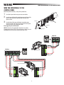
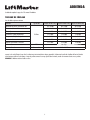
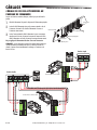
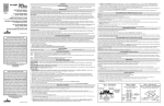
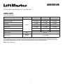
ADDENDUM
This addendum replaces the information on pages 9 and 17 of the installation manual.
WIRING CHART
Cable list and minimum thickness
Connection
Cable length 3-32 ft.
Cable length 32-65 ft.
Cable length 65-98 ft.
120 V control panel power supply
3G x 14 AWG
3G x 14 AWG
3G x 10 AWG
24 V motor power supply
2G x 14 AWG
2G x 14 AWG
2G x 10 AWG
Flashing light
2 x 14 AWG
2 x 14 AWG
2 x 14 AWG
3 x 23 AWG
3 x 23 AWG
3 x 23 AWG
Photocell receivers
4 x 14 AWG
4 x 14 AWG
4 x 14 AWG
Accessories power supply
2 x 23 AWG
2 x 23 AWG
2 x 18 AWG
Command and safety devices
2 x 23 AWG
2 x 23 AWG
2 x 23 AWG
Photocell transmitters
Type of cable
Stranded
Antenna connection
RG58
max. 65 ft.
Encoder connection
Twisted Pairs
Stranded
2 x 18 to 20 AWG
NOTE: If the length of the wire differs from that specified in the table, then you must determine the proper wire gauge based on the actual power draw of the devices
connected and the local electrical codes. For connections that require several, sequential loads, the sizes provided in the table must be re-evaluated based on actual power
draw and distances. When connecting products that are not specified in this manual, refer to the instructions provided with said products.
NOTE: Use copper conductors only.
1
WIRING
WIRE THE OPERATOR(S) TO THE CONTROL PANEL
WIRE THE OPERATOR(S) TO THE
CONTROL PANEL
When making electrical connections, use the pit for the junction boxes.
Turn off the AC power from the main power source circuit breaker.
Junction box
Insert the power cable through the watertight connector on the bottom of the
operator. Connect the wires from the power cable to the board on the
operator as shown.
Control panel
3
Insert the other end of the power cable through a watertight connector
mounted in the back of the control panel. Connect the wires from the power
cable to the terminals on the control panel as shown.
Do not apply AC power until instructed.
Right gearmotor
Left gearmotor
Junction box
NOTE: The electronic card is equipped with an amperometric sensor which
constantly monitors the motor’s drive. If the gate encounters an obstacle, the sensor
immediately detects the overload on the operator and the gate reverses.
Junction pit
Single Gate
M2 N2 E2 + E -
+
E
+
E
-
24 Vdc operator with delayed closing
N
M1 N1 E1 + E - M2 N2 E2 + E -
24 Vdc operator with delayed closing
E
+
N
+
M
E
-
C FC C FA M
N
+
ADT06
-
C FC C FA M
E
+
E
-
ADT06
N
C FC C FA M
Dual Gate
N
M
24 Vdc operator with delayed opening
2
ADT06
1
2
N
M
ADDENDA
Cet addendum remplace les pages 9 et 17 du manuel d'installation.
TABLEAU DE CÂBLAGE
Liste des câbles et épaisseurs minimum
Connexion
Type de cable
Longueur de câble 3-32 pi Longueur de câble 32-65 pi Longueur de câble 65-98 pi
Alimentation du panneau de commande 120 V
3G x 14 AWG
3G x 14 AWG
3G x 10 AWG
Alimentation du moteur 24 v
2G x 14 AWG
2G x 14 AWG
2G x 10 AWG
Témoin clignotant
2 x 14 AWG
2 x 14 AWG
2 x 14 AWG
3 x 23 AWG
3 x 23 AWG
3 x 23 AWG
Récepteurs à cellule photoélectrique
4 x 14 AWG
4 x 14 AWG
4 x 14 AWG
Alimentation des accessoires
2 x 23 AWG
2 x 23 AWG
2 x 18 AWG
Dispositifs de commande et de sécurité
2 x 23 AWG
2 x 23 AWG
2 x 23 AWG
Transmetteurs à cellule photoélectrique
Fils Plains
Connexion d'antenne
RG58
max. 65 pi.
Connexion d'encodeur
Paires torsadées
2 x 18 to 20 AWG
REMARQUE : Si la longueur du fil diffère de celle spécifiée dans le tableau, vous devez déterminer le bon calibre de fil selon la puissance réelle tirée par les dispositifs
connectés et les codes électriques locaux. Pour les connexions qui nécessitent plusieurs charges séquentielles, les dimensions fournies dans le tableau doivent être réévalués
selon la puissance réelle tirée et les distances. Lorsque des produits connectés ne sont pas spécifiés dans le manuel, consulter les instructions fournies avec ces produits.
REMARQUE : Utilisation exclusive de câbles en cuivre.
3
CÂBLAGE
CÂBLAGE DE OU DES ACTIONNEURS AU PANNEAU DE COMMANDE
CÂBLAGE DE OU DES ACTIONNEURS AU
PANNEAU DE COMMANDE
Lorsque vous faites des connexions électriques, utiliser le puit pour les boîtes de
jonction.
1
2
Boîte de jonction
Éteindre l'alimentation CA à partir du disjoncteur de l'alimentation principale.
Insérer le câble d'alimentation à travers le connecteur étanche au bas de
l'actionneur. Connecter les fils du câble d'alimentation à la carte sur
l'actionneur comme montré.
Panneau de commande
Moteur à engrenage droit
3
Insérer l'autre extrémité du câble d'alimentation à travers un connecteur
étanche monté à l'arrière du panneau de commande. Connecter les fils du
câble d'alimentation aux bornes du panneau de commande comme montré.
Ne pas appliquer l'alimentation CA avant d'en avoir l'instruction.
Moteur à engrenage gauche
Boîte de jonction
Puit de jonction
REMARQUE : La carte électronique est munie d'un capteur ampérométrique qui
surveille constamment l'entraînement du moteur. Si la barrière rencontre un
obstacle, le capteur détecte immédiatement la surcharge sur l'actionneur et la
barrière s'inverse.
Barrière simple
M2 N2 E2 + E -
+
E
+
E
N
M1 N1 E1 + E - M2 N2 E2 + E -
C FC C FA M
Actionneur 24 Vcc avec fermeture retardée
Actionneur 24 Vcc avec fermeture retardée
E
+
N
+
M
C FC C FA M
E
-
C FC C FA M
+
N
Actionneur 24 Vcc avec ouverture retardée
ADT06
-
01-36906
E
+
E
-
ADT06
N
N
M
© 2013, The Chamberlain Group, Inc. – All Rights Reserved – Tous droits réservé
ADT06
-
Barrière double
N
M