1
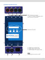
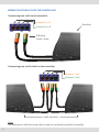
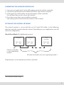
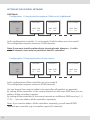
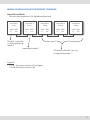
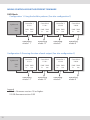
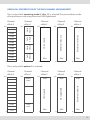
Controller
Manual
version 3.1
2
CONTENTS
Introduction4
Safety instructions5
How to replace the fuses6
Controller description7
Wiring the starcloth to the controller
8
Connecting the ShowLED controller9
Setting up the control network9
Stand Alone Mode9
DMX Mode10
Mixing controllers with different firmware
11
Stand Alone Mode11
DMX Mode12
The operator console and the menu structure
13
Flowchart of the menu structure14
Description of the parameters16
Graphical presentation of the DMX channel arrangement
19
Tips and tricks20
FAQ’s20
XLR output detail20
Troubleshooting21
Contact Information & Support channels
21
Technical data22
Declaration of conformity23
3
INTRODUCTION
Congratulations on your recent purchase of a ShowLED* Controller with the following
features:
• 8 output channels for driving LEDS
• DMX compatible
- The DMX signal is cleaned up and amplified every time it passes through a controller!
• Two or more controllers can be synchronised
• Chase patterns
- Stand alone or selected by the DMX signal
- Selection of hard or soft chase
- Variable chase speed
- A number of predefined patterns
• Interactive operator console
- The parameters of the controller are accessible though the LCD and menu buttons.
e.g. The DMX base address
• The LED outputs are protected against short circuit
• The supply voltage can vary between 90 and 250 Vac
• Uses standard cables
• Energy efficient
• Full range DMX-addressing
• Improved dimmer curve
Notes:
This manual applies to firmware version 1.0 or higher and hardware versions 2.0 and
above.
Please consult our website for possible errata and modifications.
*ShowLED is our brand name for LED-products we develop for the entertainment
industry.
4
SAFETY INSTRUCTIONS
!
WARNING
To avoid electric shock the power cord protective grounding must be connected to
ground.
Make sure you understand the function of each connection before you connect it. See
that all connections are made correctly before turning on the controller.
Always disconnect the device from the mains supply when connecting the signal
leads, the power cord should be connected last.
Do not apply voltage higher than 250 Vac to the device. (See also technical data)
In case of an emergency, you can disconnect power from the device by pulling out the
power cord. Keep the power cord easily accessible at all times.
If your application set-up does not allow easy access to the power cord, install a
mechanical circuit breaker in the supply-line, going to the device.
The device has 2 fuses placed inside; replace them only with the correct type. See next
page how to replace them.
If the controller hangs on a starcloth and is not supported by a floor or a table, you
must secure it with a mechanical safety. The connecting cables are NOT mechanical
safeties! If you are not familiar with mechanical safeties, feel free to contact us, we can
provide you with advice.
Take care with the environmental limits. Do not exceed them. (See technical data)
Keep a minimum distance of 1 meter between you (or the audience) and the LEDs.
Do not stare into the LEDs, especially when narrow angle LEDs are used.
This device is designed and tested for driving LEDs; do not use it for other purposes.
Do not expose the controller to water (rain) or direct sunlight.
Do not subject to excessive shock by dropping the unit.
5
How to replace the fuses
Disconnect the powercord. Unscrew the 4 bolts on the two sides of the device and the
4 top screws of the XLR connectors of the LED outputs (You need a PH1 screwdriver).
Remove the top of the device (it is not necessary to disconnect the flat cable you
encounter). Locate the fuse holders marked on the PCB as F1 and F2. You can open the
fuse holders by turning the caps counter clockwise.
Determine which fuse is blown. (If you are not sure, replace both) Replace the fuse(s)
with the right kind (fuse 2.0A slow-blow 5x20 mm). Replace the caps together with
the fuses and lock them by turning clockwise.
Put the top of the device back into position and fasten the 4 little bolts on the two
sides of the device and the 4 top screws of the XLR connectors of the LED outputs.
Reconnect the powercord and check if the device is working properly.
6
CONTROLLER DESCRIPTION
LED Output connectors
(2 pairs of 5 pole XLR-plugs each
pair controls 4 channels)
Operator Console
A: DMX input (5 pole XLR)
B: DMX output (5 pole XLR)
C: MAINS input (IEC power inlet)
Note:
The pictures are not to scale!
A
B C
7
WIRING THE STARCLOTH TO THE CONTROLLER
Connecting one cloth to the controller
channels 1 to 4
Starcloth
channels 5 to 8
XLR-plug
5 pole / male
Connecting two small cloths to the controller
channels 1 to 4
channels 5 to 8
small starcloths
Note:
The connectors with the same colour code are switched in parallel (internally)
8
CONNECTING THE SHOWLED CONTROLLER
1. Connect your application1 to the LED output connectors of the controller.
2. Connect the powercord to the MAINS (90-250V) input of the controller.
3. At this point you will need to set the parameters of the controller.
You will learn how to do so from this manual.
4. If you have more than one controller to connect.
See setting up the control network, further in this manual.
SETTING UP THE CONTROL NETWORK
The control network is set up with the use of 5 pole XLR cables. In the following
drawings only the control network is drawn. Depending on your application, you will
choose a configuration.
Stand Alone Mode (No lightboard present)
Controller
1
Controller
2
Last
Controller
DMX DMX
in
out
DMX DMX
in
out
DMX DMX
in
out
The first controller
is set to operating
mode 0
All other controllers are set to operating mode 1
All parameters can be altered on the first controller.
1 For instance, a starcloth, a logo, …
9
SETTING UP THE CONTROL NETWORK
DMX Mode
Configuration 1: Using the built-in patterns (With use of a lightboard)
Lightboard
Controller 1
Controller 2
Last Controller
DMX
out
DMX DMX
in
out
DMX DMX
in
out
DMX DMX
in
out
In this configuration controller 1 is set in mode 10; all the others are set in mode 1.
This configuration requires minimum 5 DMX channels.
Note: if you want to add another device (moving heads, dimmers,...) to this
control network, it can only be put before the first controller!
Configuration 2: Dimming function of each output
Lightboard
Controller 1
Controller 2
Last Controller
DMX
out
DMX DMX
in
out
DMX DMX
in
out
DMX DMX
in
out
In this configuration all the controllers are set in mode 8.
This configuration requires minimum 8 DMX channels.
You can choose if you want to address the controllers all together or separately.
By setting all the controllers in this control network on the same DMX base you can
address all the controllers together.
By setting all the controllers in the control network on a different DMX base (e.g. 1, 9,
17, 25 …) you can address all the controllers separately.
Note: if you want to address all the controllers separately, you will need 8 DMX
channels per controller. (e.g. 4 controllers require 32 channels)
10
MIXING CONTROLLERS WITH DIFFERENT FIRMWARE
Stand Alone Mode
Master slave operation (No lightboard present)
Controller 1
V 1.0 >
Controller 2
V 1.0 >
Controller 3
V 0.30
Controller 4
V 0.30
Controller 5
V 0.30
DMX DMX
in
out
DMX DMX
in
out
DMX DMX
in
out
DMX DMX
in
out
DMX DMX
in
out
The first controller
is set to operating
mode 2
operating mode 3
All other controllers are set
to operating mode 1
Legend
V 1.0 >: firmware version 1.0 or higher
V 0.30: firmware version 0.30
11
MIXING CONTROLLERS WITH DIFFERENT FIRMWARE
DMX Mode
Configuration 1: Using the build in patterns (See also configuration 2)
Lightboard
DMX
out
Controller 1
V 1.0 >
Controller 2
V 1.0 >
Controller 3
V 0.30
Controller 4
V 0.30
DMX DMX
in
out
DMX DMX
in
out
DMX DMX
in
out
DMX DMX
in
out
operatingoperatingoperatingoperating
mode 11
mode 12
mode 8
mode 8
Configuration 2: Dimming function of each output (See also configuration 3)
Lightboard
DMX
out
Controller 1
V 1.0 >
Controller 2
V 1.0 >
Controller 3
V 0.30
Controller 4
V 0.30
DMX DMX
in
out
DMX DMX
in
out
DMX DMX
in
out
DMX DMX
in
out
operatingoperatingoperatingoperating
mode 12
mode 12
mode 8
mode 8
Legend
V 1.0 >: firmware version 1.0 or higher
V 0.30: firmware version 0.30 12
THE OPERATOR CONSOLE AND THE MENU STRUCTURE
The operator console consists of an LCD and three buttons.
This console is the physical interface that lets you access a menu structure.
The menu structure lets you modify the parameters of the device.
The first button (PRG) has a double function, depending on where you are in the menu
structure; the function can be an Escape or a Confirmation.
The UP button lets you navigate through the structure or increment a parameter.
The DOWN button lets you navigate through the structure or decrement a parameter.
A flowchart of the menu structure is given on the next page. The structure has three
types of submenus, namely actions, set-up parameters and operational parameters.
Actions
Exit no changes
Escape function, the previously saved parameters are restored.
Return default
The parameters are restored to the factory defaults.
Broadcast parameters
Passes the parameters to the other controllers in the DMX-chain.
Exit and save
After altering the parameters and the parameters are satisfying,
you must save them
Firmware Vx.xx
Displays the current firmware of the device. It’s an aid to help us
to give you additional support.
Set-up parameters
Operating mode
DMX base
Operational parameters
Pattern type
Pattern behaviour
Chase speed
Minimum intensity
Maximum intensity
You need to alter only the set-up parameters when the set-up of your application
changes. You will find an explanation of the parameters in section “description of the
parameters”.
13
FLOWCHART OF THE MENU STRUCTURE
Idle message, in this state the LCD backlight is dimmed
www.showled.com
Escape, no changes are made
PRG
PRG
EXIT NO CHANGES
UP
Returns the device to the
default settings
PRG
RETURN DEFAULT
UP
Send the parameters to other
devices in the chain
PRG
PRG
PRG
DN
EXIT AND SAVE
UP
Escape, no changes are made
DN
BROADCAST PARAM
UP
Exits and saves your changes
DN
DN
FIRMWARE Vx.xx
UP
DN
See next page
14
Modify values with the UP and DN buttons
OPERATING MODE
UP
Only available when operating mode 0 or 2 is selected.
000
PRG
000
PRG
000
PRG
000
PRG
000
DN
MIN INTENSITY
UP
PRG
DN
CHASE SPEED
UP
000
DN
PATTERN BEHAVIOUR
UP
PRG
DN
PATTERN TYPE
UP
000
DN
DMX BASE
UP
PRG
DN
MAX INTENSITY
15
DESCRIPTION OF THE PARAMETERS
Operating mode
This is the first parameter you need to set before entering the other ones. Depending on
the configuration of your application you must choose a certain operating mode.
See also section “Setting up the control network” for more clarity.
Mode
DMX channel
requirements
Description
Access to the
operational parameters
Dimmer
curve
0
*
Stand-alone operation (Master)
On the controller (menus)
Improved
1
*
Stand-alone operation (Slave,
listens to other controller in
mode 0)
*
Improved
2
*
Stand-alone operation (Master)
On the controller (menus)
Standard
3
*
Stand-alone operation (Slave,
listens to other controller in
mode 0)
*
Standard
4
*
reserved
*
*
5
*
reserved
*
*
6
*
reserved
*
*
7
*
reserved
*
*
8
8
Dimming function of each
output
*
Improved
9
5
Pattern type, Pattern behaviour,
Chase speed, Min. Intensity, Max.
Intensity
By the DMX signal
Improved
10
5
Pattern type, Pattern behaviour,
Chase speed, Min. Intensity, Max.
Intensity (solves synchronisation
problems)
By the DMX signal
Improved
11
5
Pattern type, Pattern behaviour,
Chase speed, Min. Intensity, Max.
Intensity (solves synchronisation
problems)
By the DMX signal
Standard
12
8
Dimming function of each
output
*
Standard
13
*
reserved
*
*
14
*
reserved
*
*
*
reserved
*
*
15
*: Doesn’t apply
Notes
Mode 0: The controller will act as a lightboard for the other controllers.
Mode 9, 10 and 11: You can address remotely the operational parameters
by the DMX-signal. It will save you time; you don’t have
to program your own sequences.
16
DMX base
Use this parameter to set the DMX base address of the ShowLED controller.
The DMX base address1 can be set between 1 and 504.
The following built-in patterns are only available if operating mode 0, 2, 9, 10 or 11
is selected!!! If operating mode 0 or 2 is selected, they are available on the operator
console. If operating mode 9, 10 or 11 is selected, they are available through the DMX
signal.
Pattern Type
(Channel offset 0)
DMX value
Function
Description
0.. 7
All Channels OFF
*
8.. 31
Chase Pattern 1
Random, min. 3 channel on
32.. 55
Chase Pattern 2
Special
56.. 79
Chase Pattern 3
Sequence with 4 channels on
80.. 103
Chase Pattern 4
Sequence with 5 channels on
104.. 127
Chase Pattern 5
Sequence with 6 channels on
128.. 151
Chase Pattern 6
Running light 7 channels on
152.. 175
Chase Pattern 7
Running light 6 channels on
176.. 199
Chase Pattern 8
Running light 5 channels on
200.. 223
Chase Pattern 9
Running light 4 channels on
224.. 247
Chase Pattern 10
STROBE
248.. 255
All Channels ON
*
*: Forced operation, all other parameters have no influence.
1 The DMX base address is also known as the “DMX start address”
17
Pattern Behaviour
(Channel offset 1)
DMX value
Description
0.. 63
Soft chase
64.. 127
Hard chase
128.. 191
Soft chase, inverted pattern
192.. 255
Hard chase, inverted pattern
Chase Speed
(Channel offset 2)
DMX value
Description
0
Minimum speed
..
255
Maximum speed
Minimum Intensity
(Channel offset 3)
Limiter function sets the minimum intensity level. When set to a value higher than
zero, the LEDs will not dim completely.
Maximum Intensity
(Channel offset 4)
Limiter function sets the maximum intensity level. When set to a value lower than 255,
the LEDs will not light up at full capacity.
Note: the maximum intensity has a higher priority than the minimum intensity!
18
GRAPHICAL PRESENTATION OF THE DMX CHANNEL ARRANGEMENT
This is only valid if operating mode 9, 10 or 11 is selected. This presentation can be
of help when you are using a low-cost DMX lightboard.
Channel ChannelChannel ChannelChannel
offset 0
offset 1
offset 2
offset 3
offset 4
Patt10
Patt9
Soft
Chase
Patt8
Patt7
Patt6
Hard
Chase
Patt5
Patt4
Patt3
Soft
Chase
Patt2
Patt1
0
255
Min.
All off
0
Max.
0
Max.
255
Min.
0
Max.
Maximum Intensity
255
Minimum Intensity
255
Chase speed
All on
Hard
Chase
255
Min.
0
This is only valid if pattern 2 is selected.
Channel ChannelChannel ChannelChannel
offset 0
offset 1
offset 2
offset 3
offset 4
Many
stars
255
255
Max.
255
Max.
Min.
Min.
Min.
Few
stars
Patt2
All off
0
Max.
Maximum Intensity
255
Not applicable
All on
Chase speed
255
0
0
0
0
19
TIPS AND TRICKS
If you have altered one or more parameters, make sure to leave the menu with the
action “exit and save”. Otherwise your settings will be lost when the controller is
turned off.
A quick way to make the LEDs light up is to set the controller in default mode.
Push the PRG-button, the DOWN-button and again the PRG-button.
FAQ’s
1. How can I read the firmware version?
Press the PRG button once. Press 4 times the Down button.
Now you’re able to read the firmware version.
2. Where can I find which hardware version my controller has got?
At the back of the device you’ll find a barcode (serial number).
The code is built as follows, for example: *025608D02000092*
These three digits represent
the hardware version.
020 reads as version 2.0
3. What is the maximum length of the cable between the controller and the cloth?
You can determine the maximum length of the cable by using the following table.
Number of LEDs in the cloth
Wire Size
(mm²)
96
128
192
256
0,5
27m
20m
13m
10m
0,75
40m
30m
20m
15m
1,0
53m
40m
27m
20m
XLR OUTPUT DETAILS
XLR port 1 and 2 (orange)
Pin 1 - channel 1
Pin 2 - channel 2
Pin 3 - channel 3
Pin 4 - channel 4
Pin 5 - common anode
20
XLR port 3 and 4 (green)
Pin 1 - channel 5
Pin 2 - channel 6
Pin 3 - channel 7
Pin 4 - channel 8
Pin 5 - common anode
TROUBLESHOOTING
The controller won’t turn on!
Make sure you have tension on the power outlet. (A multimeter can be helpful in checking
this!) If you are sure that you have tension from the power outlet, connect the powercord
to the device.
If the LEDs are not lit and there is no text on the display and the display backlight is not
lit, the fuse(s) are probably blown. If you need to replace the fuses make sure to follow the
procedure explained in the section “Safety instructions”
The LEDs don’t light up!
If the display works but the LEDs don’t light up, set the controller in default mode. Push
the PRG-button, the DOWN-button and again the PRG-button.
If the LEDs are still not lit the problem probably lies in the wiring.
For all further questions or remarks, please visit the support section of our website at
www.showled.com!
In order to serve you in a better way, we invite you to send suggestions and feedback to
[email protected] .
CONTACT INFORMATION & SUPPORT CHANNELS
• Visit the support section of our website at www.showled.com.
Here you will find up-to-date FAQ’s and Tips and Tricks.
• Send your questions to [email protected], we will reply to you as soon
as possible.
•
Place a call to ShowLED FZC
Tel: +971 6 557 83 07
Office hours: Sunday through Thursday from 09.00 to 18.00.
Fridays and Saturdays we are closed.
• Note that we are in the GMT-zone +4 hour.
Here are some useful links to convert time zones:
www.worldtimeserver.com • www.timezoneconverter.com • www.timeanddate.com
• Contact address
ShowLED FZC • P.O. Box : 120888 • Warehouse Q4-006 • Sharjah Airport Free Zone •
Sharjah • United Arab Emirates
21
TECHNICAL DATA Specs are listed for both controllers, the LC025608DR difference is between brackets ( ).
Electrical
Input
Input voltage range
Line frequency
Input current at 100/230 V AC1
Inrush current2
Input power
Fuses
90 - 250
47 - 63
0.8 - 0.45 (0.6 - 0.4)
15
50 (33)
2 x T2.0A slow-blow3
V ac
Hz
A
A
W
5
8 (5)
40 (25)
Polymeric (PPTC)
V dc
A dc
W
Operating
Ambient temperature
Relative humidity7
5 - 45
< 80
°C
%
Storage8
Ambient temperature
Relative humidity
5 - 35
< 60
°C
%
Output4
Output voltage
Output current5
Output power
Fuses6
Environmental
Mechanical
Dimensions
Weight
1
2
3
4
5
6
7
8
22
190 x 112 x 43
1186
mm
g
at nominal load
start up current, only lasts for 2 milliseconds
placed inside the device
when the outputs are set to maximum and have a nominal load
the sum of the 8 outputs
every led output is short circuit protected by an automatically reset table fuse
no condensing
the stricter storage parameters ensure a long life of the LCD
DECLARATION OF CONFORMITY (3rd edition)
We, ShowLED FZC
P.O. Box : 120888 - Warehouse Q4-006 - Sharjah Airport Free Zone - Sharjah - UAE
Declare that the product
ShowLED Classic System, containing a subset of the following components
Controller type LC025608DR, Controller type LC051208DR,
Led string type BW-12LED, Led string type BW-16LED
is in conformity with the essential requirements of the following directives and
standards:
Low Voltage Directive (73/23/EEC)
EN 60950 (2nd Ed) Standard for safety of information technology equipment
Including amendments A1, A2, A3, A4 and A11.
EMC Directive (89/336/EEC) and 92/31/EEC
EN 55103-1
EN 55103-2
EN 55022
EN 55024
Electromagnetic compatibility for audio, video, audio-visual and
entertainment lighting control apparatus for professional use.
Part 1: Emission
Electromagnetic compatibility for audio, video, audio-visual and
entertainment lighting control apparatus for professional use.
Part 2: Immunity
Standards of radio disturbance of information technology equipment.
Standards of immunity characteristics of information technology
equipment.
Sharjah, United Arab Emirates
Kenny Janssens, Managing Director
01/9/2011
(Date of issue) (Signature of authorised person)
23
LED starcloths for:
theatres
TV studios
concerts
night clubs
exhibitions
corporate events
movie theatres
cruise ships
Visit our website for further information
or to check contact details of your local ShowLED supplier.
www.showled.com