1
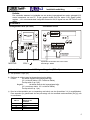
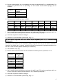
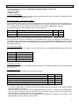
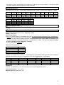
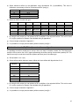
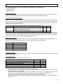
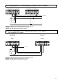
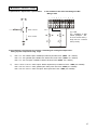
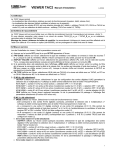
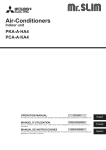
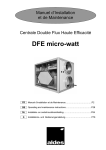
ls2
Manuel d'installation
(cid 005161, 360006)
(v.01/04)
Définition:
Boîtier de contrôle qui permet de lier le débit d’air à un signal d’entrée analogique (LS) sans nécessiter de
PC pour sa configuration. Il permet de fonctionner en liaison avec un signal 0-10V externe (sonde,
régulateur, …) ou être utilisé comme Slave en étant lié au signal de débit 0-4,5V d’un boîtier CB TACxx2
Master.
1) Schéma des boîtiers
Boîtier de puissance TAC2 (PB TAC2)
Boîtier de contrôle TACls2
1
2
3
4
5
6
7
8
CONTROLE
PUISSANCE
00W_H
L
N
TO FAN BOX
1 2 GG 3 4 5 6 G 7 8
NN
N
DD
D
SOFTSTOP
CLOSED=RUN
OPEN=STOP
MOTEUR
230V +
Specifications du câble: UTP / Cat.5 / 8 wires
Connecteurs : RJ45/8
2) Lier le débit à un signal externe 0-10V (DS1 = 0)
a) Mettre le dip-switch 1 sur 0 (off).
b) Définir la logique du lien entre le signal d’entrée et le débit:
Positive:
Le débit augmente lorsque la valeur du signal d’entrée augmente.
(0V = débit minimum, 10V = débit maximum)
Mettre le dip-switch 2 sur 0 (off).
Négative:
Le débit diminue lorsque la valeur du signal d’entrée augmente.
(0V = débit maximum, 10V = débit minimum)
Mettre le dip-switch 2 sur 1 (on).
c) Sélectionner le débit minimum de votre application à l’aide des dip-switches 3-4 (4 possibilités). Ces
valeurs sont définies comme des pourcentages du débit maximum nominal (voir § e)) du ventilateur:
DS 3-4
00
01
10
11
% débit maximum
nominal ventilateur
0 % (càd 100 m³/h)
10 %
20 %
30 %
1
d) Sélectionner le débit maximum de votre application à l’aide des dip-switches 5-6 (4 possibilités). Ces
valeurs sont définies comme des pourcentages du débit maximum nominal (voir § e)) du ventilateur:
DS 5-6
00
01
10
11
% débit maximum
nominal ventilateur
100 %
90 %
80 %
70 %
e) Débit maximum nominal par type de ventilateur:
DD 9-7TH 1/2
Débit max.
720054
2000
DD 9-9 1/2
720055
2900
DP 9-9 1/1 S 10-4TH 1/3
Débit max.
f)
720060
5700
720071
1000
DD 10-10 3/4
720056
3800
DS 10-4 1/2
720061
1500
DD 11-11 1/1
720057
4400
DS 11-4 1/2
720062
1900
DP 6-6 1/2
720058
2200
DS 12-5 3/4
720063
2600
DP 9-7TH 1/1
720059
3600
F 280-114 1/3
720077
1300
DP 9-7TH 1/2
720011
3000
(K)DF 280-114
1/2
720078
1700
Il est possible d’activer un multiplicateur égal à 50% du lien établi en fermant le contact K3 (entre les
bornes 5 et 6). Détail du raccordement: voir annexe 1.
g) Raccorder selon schémas repris en annexe 1.
h) Initialisation de l’alarme de pression (si nécessaire) : voir §4).1.
3) Lier le débit à un signal externe 0-4,5V (DS1 = 1) – configuration maître/esclave
Le but est de lier le débit du boîtier de contrôle (esclave) à celui d’un autre boîtier (maître) en récupérant
son signal de sortie représentatif du débit (utiliser les mêmes types de ventilateurs).
a) Mettre le dip-switch 1 sur 1 (on).
b) Sélectionner le rapport de débit entre le boîtier maître et esclave à l’aide des dip-switches 2 à 4.
111
Débit esclave /
débit maître
(%)
120
110
110
101
100
100
95
011
90
010
85
001
80
000
70
DS 2-3-4
c) Il est possible d’activer un multiplicateur égal à 50% du lien établi en fermant le contact K3 (entre les
bornes 5 et 6). Détail du raccordement: voir annexe 1.
d) Raccorder selon schémas repris en annexe 1.
e) Initialisation de l’alarme de pression (si nécessaire): voir §4).1.
2
4) Alarmes
Le boîtier de contrôle TACls2 comprend 3 types d’alarme: (Exemples de schémas de raccordement: voir annexe 1.
- une alarme sur la variation de pression.
- une alarme signalant une panne du ventilateur.
- des alarmes d’initialisation.
).
4.1 Alarme sur la pression.
Cette alarme permet de signaler à l’utilisateur une variation de pression par rapport à la pression de référence (selon
courbe système). Lors de l’enclenchement de cette alarme, la LED2 est allumée et le transistor branché entre les bornes
G et 2 du boîtier de contrôle est conducteur.
Comment mémoriser la pression de référence Paréf :
a) Installer le ventilateur dans son application réelle.
b) Ouvrir le boîtier de contrôle TACls2, appuyer sur le bouton SW2 jusqu’à ce que la LED1 s’allume. Le processeur
adapte automatiquement le débit pour atteindre celui d’initialisation d’alarme (60% du débit maximum de l’application),
calcule la pression du système (LED1 allumée) et la mémorise dès qu’un calcul stabilisé a pu être effectué. A ce
moment, la LED1 s’éteint, signalant la fin de mémorisation de Paréf.
Au terme de l’initialisation, 2 types de problèmes peuvent survenir (signalés par le clignotement des LED 1 et 2) :
Type d’alarme
A
B
Descriptif
Débit réel < débit demandé : le point de fonctionnement est situé
à un niveau de pression supérieur à la pression maximale
admissible au débit demandé / débit non encore atteint suite à un
démarrage.
Pression trop instable
LED 1
LED 2
7x
1x
8x
1x
Dans les 2 cas, Paréf ne peut être mémorisée et le moteur est mis en mode “softstop”. Il faut alors débrancher puis
rebrancher le câble entre le boîtier de contrôle et de puissance (connecteur RJ45). Le boîtier fonctionnera alors sans
alarme sur la pression. Si une initialisation doit malgré tout être faite, veillez à régler un point de fonctionnement stable et
compris dans la zone de travail du ventilateur (diminuer la pression, modifier le débit, placer un autre type de
ventilateur,…)
Comment fixer l’incrément:
On peut choisir un incrément parmi 4 à l’aide des dip-switches 7 et 8:
DS 7-8
Delta
00
50
01
80
10
120
11
150
0=OFF - 1=ON
Cet incrément correspond au débit d’initialisation de l’alarme, soit 60% du débit maximum de l’application.
4.2 Alarme sur le fonctionnement du ventilateur.
Cette alarme signale un disfonctionnement du ventilateur. Lors de l’enclenchement de cette alarme, la LED1 est allumée
et le transistor branché entre les bornes G et 1 du boîtier de contrôle est conducteur.
4.3 Alarmes d’initialisation
Lors de la mise sous tension du ventilateur, 5 types de problèmes peuvent se produire :
Descriptif
INIT1: Ventilateur de génération 2 non « reconnu » par le boîtier de contrôle
INIT2: Ventilateur de génération 1
INIT3: Pas de signal “vitesse de rotation” venant du moteur
INIT4: Altération des données du circuit
INIT5: Problème de détection du type de ventilateur
LED 1
6x
4x
5x
1 2,3,9 x
10 x
LED 2
1x
1x
1x
1x
1x
Dans tous les cas, retirer le câble de liaison RJ45 et le remettre. Si le problème persiste :
- Dans les 2 premiers cas (INIT1 et 2), le boîtier de contrôle n’est pas adapté au type de ventilateur. Veillez à remplacer
soit le ventilateur par un modèle adéquat, soit le type de boîtier de contrôle.
3
- Une alarme de type “INIT3” signale un manque de signal de vitesse de rotation venant du moteur. Remplacez le boîtier
de puissance TAC2. Si le problème persiste remplacer le câble RJ45. Si le problème persiste encore, remplacer le
boîtier de contrôle. Si le problème persiste toujours, remplacer le ventilateur.
- Une alarme de type “INIT4” signale une altération des données inclues dans la mémoire du boîtier TACls2. Dans un tel
cas, le boîtier de contrôle doit être remplacé.
- En cas d’alarme de type “INIT5”, remplacer le boîtier de contrôle. Si le problème persiste remplacer le ventilateur.
5) Signaux de sortie
Signal entre G-7: 0-4,5 Vdc = 0-débit max. Signal entre G-8: 0-4,5 Vdc = 0-Pa max. Impédance min. = 100 MΩ.
Débit max.
Pres. max.
DD 9-7TH
1/2
720054
2000
630
DD 9-9
1/2
720055
2900
780
DD 10-10
3/4
720056
3800
1050
DD 11-11
1/1
720057
4400
1070
DP 6-6
1/2
720058
2200
450
Débit max.
Pres. max.
DS 11-4
1/2
720062
1900
950
DS 12-5 (K)DF 280-114 (K)DF 280-114
3/4
1/3
1/2
720063
720077
720078
2600
1300
1700
1310
525
575
DP 9-7TH DP 9-7TH
1/1
1/2
720059
720011
3600
3000
630
575
DP 9-9
DS 10-4 TH DS 10-4
1/1
1/3
1/2
720060
720071
720061
5700
1000
1500
900
585
750
6) Schémas de raccordement
Voir annexe 1.
7) Données techniques
Alimentation: 230VAC (entre 208V et 240V) - Frequence : 50/60Hz
Mise à terre: ! OBLIGATOIRE !
Protection éléctrique:
Le moteur est auto-protégé contre les surcharges. Il n'est donc pas nécessaire de prévoir une protection électrique
contre les surcharges. Une simple protection contre les court-circuits suffit et doit être sélectionnée en respectant les
spécifications suivantes :
- pointe à l'enclenchement de 150 A (20A avec PB S) pendant 2 à 4 millisecondes (si disjoncteur : sélectionner une
courbe de déclenchement de type D – pouvoir de coupure 10.000A - AC3). Il est obligatoire d'utiliser la fonction
softstop afin d'éviter cette pointe.
- nous recommandons une protection de classe AM.
Calibre de la protection/moteur
Type
1/3 HP
1/2 HP
3/4 HP
1/1 HP
Calibre
4A
4A
8A
10A
Exemples indicatifs et non exhaustifs de sélection de : a) cartouches fusibles AM (10x38mm), b) disjoncteurs magnétothermiques : courbes de déclenchement D – pouvoir de coupure 10.000 A. (8A inexistant : mettre 10A)
a)
b)
Calibre
Vynckier
Merlin Gérin
Calibre
Legrand
Télémécanique
Huppertz
2A
réf
:
099/37202-000
réf : 25111
2A
réf. :130.02
réf. : DF2-CA02
réf. : D440102
4A
réf
:
099/37204-000
réf : 25113
4A
réf. :130.04
réf. : DF2-CA04
réf. : D440104
8A
n'existe
pas
n'existe
pas
8A
réf. :130.08
réf. : DF2-CA08
réf. : D440108
10A
réf
:
099/37210-000
réf
:
25115
10A
réf. :130.10
réf. : DF2-CA10
réf. : D440110
Classe d'isolation
Thermique : B / Mécanique : IP44 - les connecteurs doivent être placés vers le bas.
Températures ambiantes: -10°C / +55°C
Conformités: approuvé CE – UL
4
ls2
Installatiehandleiding
(v.01/04)
Definitie:
Een controlebox waarmee het luchtdebiet aan een analoog ingangsignaal kan worden gekoppeld (LS)
zonder tussenkomst van een PC. Er kan gewerkt worden met een extern 0-10V signaal (sonde,
regelaar,…) of in een meester-slaaf configuratie die aan het 0-4,5V signaal van een CB TACxx2 wordt
gelinkt.
1) Schema’s
Vermogensbox TAC2 (PB TAC2)
Controlebox TACls2
1
2
3
4
5
6
7
8
CONTROLE
PUISSANCE
00W_H
L
N
TO FAN BOX
1 2 GG 3 4 5 6 G 7 8
NN
N
DD
D
SOFTSTOP
CLOSED=RUN
OPEN=STOP
MOTEUR
230V +
Specificaties van de kabel: UTP / Cat.5 / 8 wires
Aansluitingen : RJ45/8
2) Het debiet aan een extern 0-10V signaal koppelen (DS1 = 0)
a) Zet dip-switch 1 op 0 (off).
b) Definieer de relatie tussen het ingangsignaal en het debiet:
Positief:
Het debiet stijgt als het ingangsignaal stijgt.
(0V = minimum debiet, 10V = maximum debiet)
Zet dip-switch 2 op 0 (off).
Negatief:
Het debiet daalt als het ingangsignaal stijgt.
(0V = maximum debiet, 10V = minimum debiet)
Zet dip-switch 2 op 1 (on).
c) Kies het minimumdebiet van uw toepassing met behulp van de dip-switches 3-4 (4 mogelijkheden).
Deze waarden zijn gedefinieerd als een percentage van het nominale maximumdebiet (zie §e)) van
de ventilatoren.
DS 3-4
00
01
10
11
% nominaal maximum
debiet van de
ventilator
0 % (dwz 100 m³/u)
10 %
20 %
30 %
5
d) Kies het maximumdebiet van uw toepassing met behulp van dip-switches 5-6 (4 mogelijkheden). De
waarden zijn gedefinieerd als een percentage van het nominale maximumdebiet (zie §e)) van de
ventilator:
DS 5-6
00
01
10
11
% nominaal maximum
debiet van de
ventilator
100 %
90 %
80 %
70 %
e) Nominaal maximumdebiet per type ventilator:
DD 9-7TH 1/2
Max debiet
DD 9-9 1/2
720054
2000
720055
2900
DP 9-9 1/1 S 10-4TH 1/3
Max debiet
f)
720060
5700
720071
1000
DD 10-10 3/4
DD 11-11 1/1
720056
3800
DS 10-4 1/2
720057
4400
DS 11-4 1/2
720061
1500
720062
1900
DP 6-6 1/2
720058
2200
DS 12-5 3/4
720063
2600
DP 9-7TH 1/1
DP 9-7TH 1/2
720059
3600
F 280-114 1/3
720077
1300
720011
3000
(K)DF 280-114
1/2
720078
1700
Het is mogelijk om een multiplicator te activeren die gelijk is aan 50% van de vastgelegde relatie, en
dit door contact K3 te sluiten (tussen klemmen 5 en 6). Aansluiting zie bijlage 1.
g) Aansluiten volgens de schema’s in bijlage 1.
h) Initialiseren van het drukalarm (indien nodig, zie § 4).1.
3) Het debiet koppelen aan een extern 0-4,5V signaal (DS1 = 1) - meester/slaaf
configuratie
Het doel is om het debiet van de controlebox (slaaf) te koppelen aan dat van een andere controlebox
(meester). Het debiet van de ‘meester’ ventimator zal dan als representatief uitgangsignaal dienen voor
dat van de ‘slaaf’ ventilator (gebruik dezelfde type ventilatoren).
a) Zet dip-switch 1 op 1 (on).
b) Kies de relatie tussen het meester en het slaaf debiet met behulp van de dip-switches 2 tot 4.
111
Debiet slaaf /
debiet meester
(%)
120
110
110
101
100
100
95
011
90
010
001
85
80
000
70
DS 2-3-4
c) Het is mogelijk om een multiplicator te activeren die gelijk is aan 50% van de vastgelegde relatie, en
dit door contact K3 te sluiten (tussen klemmen 5 en 6). Aansluiting zie bijlage 1.
d) Aansluiten volgens de schema’s in bijlage 1.
e) Initialiseren van het drukalarm (indien nodig, zie § 4).1.
6
4) Alarm
De TACd2 kast bevat 3 alarm types : (Voorbeelden aansluitingsschema: zie bijlage 1. ).
- alarm op drukwijziging
- ventilator-pech alarm
- initialisatie alarmen
4.1 Alarm op drukwijziging:
Dit alarm signaleert een drukwijziging op basis van de referentiedruk. Bij een alarm licht LED2 op en geleidt de transistor
van de controlekast tussen de klemmen G en 2.
De referentie druk Paref in het geheugen opslaan :
a) Laat de ventilator in zijn reële toepassing draaien.
b) De controlekast TACls2 openen en op de knop SW2 drukken tot LED1 oplicht. De processor aanpast automatisch het
debiet om 60% van de maximum debiet van de toepassing te halen, berekent automatisch de overeenstemmende druk
voor dit debiet (LED1 aan) en brengt deze in het geheugen zodra het systeem gestabiliseerd is (LED1 uit).
Na initialisatie kunnen 2 problemen optreden (LED 1 en LED2 knipperen) :
Alarm type
A
B
Beschrijving
Debiet < gewenst : de druk is hoger dan de maximaal toelaatbare
druk voor het gewenste debiet / debiet nog niet bereikt na starten.
Druk te veranderlijk.
LED 1
LED 2
7x
1x
8x
1x
In beide gevallen kan Paref niet in het geheugen gebracht worden en wordt de motor in “softstop” geschakeld.
Het verbindingssnoer tussen de controlekast en de vermogenkast (RJ45 connector) verwijderen en terugplaatsen. De
controlekast zal dan zonder alarm voor drukwijziging werken. Indien een dergelijk alarm noodzakelijk is moet een stabiel
werkingspunt ingesteld worden dat in het werkingsgebied van de ventilator ligt. (druk en/of debiet aanpassen, een andere
type ventilator gebruiken, ...).
Hoe het increment instellen:
Er kunnen 4 incrementen (voor een debiet = 60 van maximaal debiet van de toepassing) gekozen worden door middel
van dip-switches 7 en 8:
DS 7-8
00
01
10
11
0=OFF - 1=ON
∆Pa
50
80
120
150
4.2 Ventilator pechalarm:
Dit alarm signaleert een pech van de ventilator. Bij alarm licht LED1 op en geleidt de transistor van de controlekast tussen
de klemmen G en 1.
4.3 Initialisatie alarmen:
Bij het inschakelen van de ventilator kunnen 5 problemen optreden :
Beschrijving
INIT1: Ventilator van generatie 2 wordt niet herkend door de controlebox
INIT2: Ventilator van generatie 1
INIT3: Er komt geen toerentalsignaal door van de motor
INIT4: Verandering van de gegevens van het D2 circuit
INIT5: Probleem in detectie van de type ventilator
LED 1
6x
4x
5x
1,2,3,9 x
10 x
LED 2
1x
1x
1x
1x
1x
Probeer altijd eerst om de RJ45 kabel opnieuw te bevestigen. Indien het probleem aanhoudt :
- In de eerste 2 gevallen (INIT1 en 2) is de controlebox niet aangepast aan het type ventilato. U dient ofwel de ventilator
ofwel de controlebox te vervangen.
- Een alarm type INIT3 geeft aan dat er geen toerentalsignaal van de motor komt. Vervang de TAC2 vermogensbox.
Indien het probleem aanhoudt, vervang de RJ45 kabel. Indien het probleem aanhoudt, vervang de TACls2 controlebox.
Indien het probleem nog steeds aanhoudt, vervang de ventilator.
- Een alarm type INIT4 geeft aan dat er zich een wijziging heeft voorgedaan in het geheugen van de TACls2. In een
dergelijk geval moet de controlebox vervangen worden.
7
- Een alarm type INIT5 geeft aan dat er een probleem in de detectie van het type ventilator is. Vervang de TACls2
controlebox. Indien het probleem aanhoudt, vervang de ventilator.
5) Uitgangssignalen
Signaal tussen G-7: 0-4,5 Vdc = 0–max. debiet. Signaal tussen G-8: 0-4,5 Vdc = 0-Pa max. Min. impedance = 100 MΩ.
Max. debiet
Max. druk
DD 9-7TH
1/2
720054
2000
630
DD 9-9
1/2
720055
2900
780
DD 10-10
3/4
720056
3800
1050
DD 11-11
1/1
720057
4400
1070
DP 6-6
1/2
720058
2200
450
Max. debiet
Max. druk
DS 11-4
1/2
720062
1900
950
DS 12-5 (K)DF 280-114 (K)DF 280-114
1/3
1/2
3/4
720063
720077
720078
2600
1300
1700
1310
525
575
DP 9-7TH DP 9-7TH
1/1
1/2
720059
720011
3600
3000
630
575
DP 9-9
DS 10-4 TH DS 10-4
1/1
1/3
1/2
720060
720071
720061
5700
1000
1500
900
585
750
6) Aansluitingsschema's
Zie bijlage 1.
7) Technische gegevens
Voeding: 230VAC (tussen 208V en 240V) - Frequency : 50/60Hz
Aarding: ! VERPLICHT !
Electrische beveiliging:
De motor is intern beveiligd tegen overbelasting.Het is dus niet nodig een electrische beveiliging tegen overbelasting te
monteren. Een eenvoudige beveiliging tegen kortsluiting is voldoende en deze moet rekening houden met :
- piekstroom van 150 A (20A met PB S) gedurende 2 à 4 milliseconden bij het starten (indien met schakelaar : een
uitschakelcaracteristiek van het type D selecteren - kortsluitvermogen 10.000A - AC3). Het is verplicht de softstop
functie te gebruiken om deze piekstroom te vermijden;
- wij raden een beveiliging classe AM aan.
Kaliber van de beveiliging/motor
Type
1/3 HP
1/2 HP
3/4 HP
1/1 HP
Kaliber
4A
4A
8A
10A
Indicatieve voorbeelden van de selectie van : a) zekeringspatronen AM (10x38mm), b) magneto-thermische schakelaars :
uitschakelcaracteristiek van het type D - kortsluitvermogen 10.000 A (8A bestaat niet : 10A gebruiken).
a)
b)
Kaliber
Legrand
Télémécanique
Huppertz
Kaliber
Vynckier
Merlin Gérin
2A
2A
réf. :130.02
réf. : DF2-CA02
réf. : D440102
réf : 099/37202-000
réf : 25111
réf. :130.04
réf. : DF2-CA04
réf. : D440104
réf : 099/37204-000
réf : 25113
4A
4A
réf. :130.08
réf. : DF2-CA08
réf. : D440108
bestaat niet
bestaat niet
8A
8A
10A
réf. :130.10
réf. : DF2-CA10
réf. : D440110
10A
réf : 099/37210-000
réf : 25115
Isolatieklasse
Thermisch : B / Mechanisch : IP44 - de connectoren moeten naar beneden geplaatst worden.
Omgevingstemperatuur: -10°C / +55°C
Gelijkvormigheid: goedgekeurd CE - UL
8
ls2
Installation manual
(cid 005161, 360006)
(v.01/04)
Definition:
This control device allows to link the constant airflow of the fan to an analogical entry signal without the use of a
PC: the Link to Signal (LS) control box. The CBls2 is designed to operate with a 0-10V signal (sensor, regulator,
…) or to be used as a slave linked to the 0-4,5V output signal coming from another CB TACxx2 (master).
1) Schematic
Power Box TAC2 (PB TAC2)
Control Box TACls2
1
2
3
4
5
6
7
8
CONTROLE
PUISSANCE
00W_H
L
N
TO FAN BOX
1 2 GG 3 4 5 6 G 7 8
NN
N
DD
D
SOFTSTOP
CLOSED=RUN
OPEN=STOP
MOTEUR
230V +
Cable specification: UTP / Cat.5 / 8 wires
Connector : RJ45/8
2) Link constant airflow to 0-10V signal (DS1 = 0)
a) Set dip-switch 1 on 0 (off).
b) Define logical relation between airflow and signal:
Positive:
Negative:
Airflow increases as signal value increases.
(0V = minimum airflow, 10V = maximum airflow)
Set dip-switch 2 on 0 (off).
Airflow decreases signal value increases.
(0V = maximum airflow, 10V = minimum airflow)
Set dip-switch 2 on 1 (on).
c) Select minimum airflow of the application using dip-switches 3-4 (4 possibilities). This value is defined
as a percentage of the fan’s maximum airflow see § e):
DS 3-4
00
01
10
11
% fan’s maximum airflow
Minimum airflow (100 m³/h)
10 %
20 %
30 %
9
d) Select maximum airflow for the application using dip-switches 5-6 (4 possibilities). This value is
defined as a percentage of the fan’s maximum airflow (see § e):
DS 5-6
00
01
10
11
% fan’s maximum airflow
100 %
90 %
80 %
70 %
e) Maximum airflow for each fan type:
DD 9-7TH 1/2
ID code
Max airflow.
DD 9-9 1/2
720054
2000
720055
2900
DP 9-9 1/1 S 10-4TH 1/3
ID Code
Max airflow
f)
720060
5700
DD 10-10 3/4
720056
3800
DS 10-4 1/2
720071
1000
720061
1500
DD 11-11 1/1
DP 6-6 1/2
720057
4400
DS 11-4 1/2
720058
2200
DS 12-5 3/4
720062
1900
720063
2600
DP 9-7TH 1/1
720059
3600
F 280-114 1/3
720077
1300
DP 9-7TH 1/2
720011
3000
(K)DF 280-114
1/2
720078
1700
By using the K3 contact you can activate a 50% multiplier to the requested airflow. This can be used
for « night » position for instance. See detailed wiring in appendice 1.
g) Connect as per schematic of appendix 1.
h) It is possible to set up a pressure alarm (without sensors): see §4.1.
3) Link airlow to a 0-4,5V (DS1 = 1) – master/slave configuration
It is possible to use this control box to set up a fan as a ‘slave’ of another ‘master’ fan. This feature will
setup the CB to receive the 0-4.5V signal representing the airflow coming from another (master) CB. This
feature can only be used when both fans (master and slave) are of the same type.
a) Set dip-switch 1 on 1 (on).
b) Select airflow relation between master airflow and slave airflow with dip-switches 2 to 4.
111
‘Slave’ airflow / ‘Master’ airflow
(%)
120
110
110
101
100
100
95
011
010
90
85
001
80
000
70
DS 2-3-4
c) By using the K3 contact you can activate a 50% multiplier to the requested airflow. This can be used
for « night » position for instance. See detailed wiring in appendice 1.
d) Connect as per schematic of appendix 1.
e) It is possible to set up a pressure alarm (without sensors): see §4.1.
10
4) Alarm
The TACls2 allows 3 types of alarms: (Examples of wiring diagram: see appendix 1.
- Pressure variation alarm
- Motor failure alarm
- Initialization alarms
).
4.1 Pressure rise alarm:
This alarm will inform the user of a pressure rise compared to the reference (initial) pressure. When this warning is
engaged, LED2 is lit and the transistor between terminal G and 2 of the control board is conductive.
How to set the reference (initial) Paréf :
a) Install the fan in its real application.
b) Open the TACls2 control box. Be sure that the air system is reflecting the system as it will be when functioning. Press
SW2 until LED1 is ON. The microprocessor then automatically set the airflow to 60% of the maximum airflow of the
application, determines the pressure of the system for this airflow (LED1 is ON). The microprocessor memorizes the
pressure when it is stable (LED1 is OFF).
At the end of the initialization, 2 kinds of problem can occur (LED1 and 2 are blinking) :
Alarm type
Description
LED 1 LED 2
A
Real airflow < requested airflow : pressure level higher than the
maximum allowed pressure corresponding to the set airflow /
7x
1x
airflow not yet stabilized after starting.
B
Unstable pressure
8x
1x
In both cases, Paréf can not be memorized and the motor is set in “softstop” mode. You have to unplug and replug the
cable between the control and the power boards (RJ45 connector). The control box will then work without pressure
alarm. If such an alarm has nevertheless to be used, set a stable working point included in the working zone of the fan
(decrease the pressure, modify the airflow, install an other type of fan, …).
How to set the increment:
The increment is set by using dip switches 7 and 8. This table shows the dip-switches positions corresponding to the
pressure change increments (corresponding to 60% of the maximum airflow of the application).
DS 7-8
000
001
010
111
0=OFF - 1=ON
∆Pa
25 Pa
50 Pa
75 Pa
300 Pa
4.2 Motor failure alarm:
This warning signals automatically a motor failure. When activated, LED1 is lit and the transistor between G and 1 on the
control board is conductive.
4.3 Initialization alarm:
When you set the power ON, 5 kinds of problem can occur :
Description
INIT1: Generation2 fan not recognized by TAC2 control box
INIT2: First generation motor program
INIT3: No RPM feedback from the motor
INIT4: Data damage in D2 control box
INIT5: Problem in detection of the fan type
LED 1
6x
4x
5x
1,2,3,9 x
10 x
LED 2
1x
1x
1x
1x
1x
First, always unplug/replug the RJ45 connector. And if the problem persists :
In case of INIT 1 or 2, the control box is not adapted to the motor program. Either replace the control box or the fan
whatever is the most suitable solution.
INIT3 alarm means no rpm feedback from the motor. Replace the power box. If the problem persists, replace the
RJ45 cable. If the problem persists, replace the control box. If the problem still persists, replace the fan.
INIT4 alarm means data in the memory is damaged. The control box must be replaced.
INIT5 alarm means there is a problem to detect the fan type. Replace the control box. If the problem persists,
replace the fan.
11
5) Feedback signals
Signal between G-7: 0 - 4,5 Vdc = 0-max. airflow. Between G-8: 0 - 4,5 Vdc = 0-Pa max. Min. impedance = 100 MΩ.
Max. airflow
Max. pres.
DD 9-7TH
1/2
720054
2000
630
DD 9-9
1/2
720055
2900
780
DD 10-10
3/4
720056
3800
1050
DD 11-11
1/1
720057
4400
1070
DP 6-6
1/2
720058
2200
450
Max. airflow
Max. pres.
DS 11-4
1/2
720062
1900
950
DS 12-5 (K)DF 280-114 (K)DF 280-114
3/4
1/3
1/2
720063
720077
720078
2600
1300
1700
1310
525
575
DP 9-7TH DP 9-7TH
1/1
1/2
720059
720011
3600
3000
630
575
DP 9-9
DS 10-4 TH DS 10-4
1/1
1/3
1/2
720060
720071
720061
5700
1000
1500
900
585
750
6) Wiring diagrams
See appendix 1.
7) Technical data
Supply : 230VAC (between 208V and 240V) - Frequency : 50/60Hz
Grounding : ! COMPULSORY !
Electrical protection :
The motor is self-protected against overloading. It is thus NOT necessary to install an electrical overload protection
device. We advise using a short circuit protection device with the following specifications :
- Starting peak of 150 A (20A using a PB S) for 2 to 4 milliseconds. The “softstop” function has to be used to avoid
this peak.
- We recommend a class AM protection device.
Recommended protection calibre/motor type
Type
1/3 HP
1/2 HP
3/4 HP
1/1 HP
Calibre
4A
4A
8A
10A
Indicative non exhaustive list of : a) AM (10x38mm) fuses with manufacturers references, b) references of thermo
magnetic circuit breakers (disjoncteur): select it with D type “slow” reaction curve – cutting power of 10.000A - AC3.
a)
b)
Calibre
Legrand
Télémécanique
Huppertz
Calibre
Vynckier
Merlin Gérin
2A
réf. :130.02
réf. : DF2-CA02
réf. : D440102
2A
réf : 099/37202-000
réf : 25111
4A
réf. :130.04
réf. : DF2-CA04
réf. : D440104
4A
réf : 099/37204-000
réf : 25113
8A
réf. :130.08
réf. : DF2-CA08
réf. : D440108
8A
does not exist
does not exist
réf. :130.10
réf. : DF2-CA10
réf. : D440110
réf : 099/37210-000
réf : 25115
10A
10A
Insulation class
Thermal : B / Mechanical : IP44 - the connectors must be oriented downwards.
Ambiant temperatures : -10°C / +55°C
Conformities : CE – UL approved
12
ANNEXE 1 – BIJLAGE 1 – APPENDIX 1
Schémas de raccordement / Aansluitingsschema's / Wiring diagrams
CONTROL
POWER
Puissance/Vermogen/Power .
L
La borne de terre doit toujours être raccordée.
N
De aarding moet altijd aangesloten worden.
The fan must always be grounded.
MOTOR
230V +
Contrôle/Stuuring/Control .
Câbles de contrôle : utiliser l’ un des
types suivants (blindé).
Sturing kabels : één van de volgende
type moet gebruikt worden
(afgeschermd).
Control cables : one of following type
cable
has to be used
(armoured).
1)of UN
débit/EEN
debiet/ONE
airflow
LIYCY
LI2YCHM2
LIFYCYB
LIYCPY
LIYCPCY
LI2YCHM2
LIYSTY
LI2YSTCY
1) Start-stop ventilateur / Start-stop ventilator / Start stop fan .
SW2
1
2
G
G
3
4
5
6
G
7
Dip-switches
8
1
2
3
4
5
6
7
8
00W_H
Closed = “high” airflow
Open = softstop
TO FAN BOX
1 2 GG 3 4 5 6 G 7 8
NN
N
DD
D
SOFTSTOP
CLOSED=RUN
OPEN=STOP
Attention: utilisez des contactes externe dorés (courant = 50 µA).
Opgelet: gebruikt vergulde contacten (stroom = 50 µA).
Caution: use gold plated contacts (current = 50µA).
13
2) Lien avec signal 0-10V / Verbinding aan 0-10V signal / Link to 0-10 signal
FAN 2
FAN 1
1
2
G
G
3
4
5
.
6
G
7
8
1
2
G
G
3
4
5
6
G
7
8
0-10V IN
K1
K3
Attention: utilisez des contactes externe dorés (courant = 50 µA).
Opgelet: gebruikt vergulde contacten (stroom = 50 µA).
Caution: use gold plated contacts (current = 50µA).
3) Lien avec signal maître 0-4,5V / Verbinding aan meester 0-4,5V signaal /
/ Link to master 0-4,5V signal
1
2
G
“MASTER”
“SLAVE”
FAN 1
FAN 2
G
3
4
5
6
G
7
8
1
2
G
G
3
4
5
6
G
7
8
0-10V IN
K1
K3
Attention: utilisez des contactes externe dorés (courant = 50 µA).
Opgelet: gebruikt vergulde contacten (stroom = 50 µA).
Caution: use gold plated contacts (current = 50µA).
14
Alarmes / Alarmen / Alarms .
1. Spécifications / Specificaties / Specifications
2. Raccordement à des LED / Aansluiting aan LED /
Wiring to LED
1
1 or 2
Vmax = 25 Vdc
Imax = 50 mA
2
G
G
3
4
5
6
G
7
8
Alarm 2
Alarm 1
(4 )= LED
(5) = resistance to limit
current (example : 4K7
for a low current LED (≈
2mA) 1K0 for a normal
LED (≈ 10mA)
G
3. Raccordement à des éléments de puissance / Aansluiting aan vermogenscomponenten /
Wiring to power components using relays
1)
Imax = 1A - 24V: utiliser l’option ‘’Satellite pour alarmes par relais TAC2’’ (SAR2 - cid = 005012)
Imax = 1A - 24V: gebruikt optie ‘’Satelliet voor alarmen door relais TAC2’’ (SAR2 - cid = 005012)
Imax = 1A - 24V: use option ‘’Satellite for alarms via relays TAC2’’ (SAR2 - cid = 005012)
2)
Imax = 10A AC1 / 5A AC3 - 230V: l’option ‘’Boîtier de puissance pour alarmes TAC2’’ : APB2 (cid = 005065)
Imax = 10A AC1 / 5A AC3 - 230V: gebruikt optie ‘’Alarm power box TAC2’’: APB2 (cid = 005065)
Imax = 10A AC1 / 5A AC3 - 230V: use option ‘’Alarm power box TAC2’’: APB2 (cid = 005065)
15