1
n2
Manuel d'installation
(v.01/03)
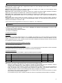
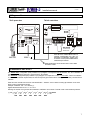
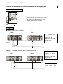
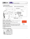
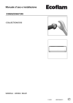
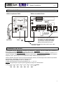
1) Schéma des boîtiers
Boîtier de puissance TAC2
Boîtier de contrôle TACn2
1
2
3
4
5
6
7
8
CONTROLE
PUISSANCE
00W_H
L
N
TO FAN BOX
1 2 GG 3 4 5 6 G 7 8
N
NN
RS485
D
DD
SOFTSTOP
RS485
NORMAL
TERMINATION
CLOSED=RUN
OPEN=STOP
MOTEUR
Si le boîtier N2 est installé en bout d’une
ligne physique de communication, placer
ce cavalier en position ‘termination’,
sinon le laisser sur la position ‘normal’.
Maximum 20 terminaisons par réseau.
230V +
Specifications du câble: UTP / Cat.5 / 8 wires / Lmax = 100m
Connecteurs : RJ45/8
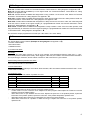
2) Installation: SAC ou NC?
La configuration de type “Stand alone” permet de (re-)configurer un ventilateur à la fois. La liaison PC , Interface ,
Boîtier TACn2 est temporaire. Utiliser le programme EOLe2_SA.
La configuration de type “Réseau permanent” permet de (re-)configurer un ensemble de ventilateurs. La liaison PC ,
Interface , Boîtiers TACn2 est généralement présente en permanence, mais peut être temporaire: “Réseau permanent
temporaire” (TNC – par exemple lors de l’utilisation de modem). Utiliser le programme EOLe2.
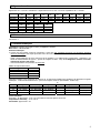
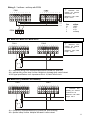
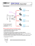
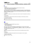
Chaque ventilateur du réseau doit avoir sa propre identification (adresse). Cet adressage se fait à l’aide des dip-switches
2 à 8 du boîtier. L’identification se fait par un système binaire.
Exemple: l’adresse du ventilateur ‘100’ = ’X-1100100’ (*).
Le chiffre décimal maximum ne peut jamais dépasser 127 = x – 1111111.
Attention: tout doublon dans un même réseau engendre des erreurs de communications.
6
5
4
3
2
1
0
(*) 100 = (1 x 2 + 1 x 2 + 0 x 2 + 0 x 2 + 1 x 2 + 0 x 2 + 0 x 2 ) = 01100100
= ( 64 + 32 + 0 + 0 + 4 + 0 + 0 ) = 100
DS2
DS3 DS4
DS5
DS6 DS7
DS8
1
3) Modes de fonctionnement
Mode CA: Débit constant. Détail: voir ″Fiche technique TACn2 Mode CA″. Schémas de raccordement: voir annexe 1- .
Mode LS: Débit constant modulé par un signal 0-10V. Détail: voir ″Fiche technique TACn2 Mode LS″. Schéma de
raccordement: voir annexe 1- .
Mode CS: Débit constant modulé pour maintenir constante une consigne 0-10V. Détail: voir ″Fiche technique TACn2
Mode CS″. Schéma de raccordement: voir annexe 1- .
Mode CFP: Débit constant modulé pour maintenir constante une consigne de pression statique calculée du ventilateur.
Détail: voir ″Fiche technique TACn2 Mode CFP″. Schéma de raccordement: voir annexe 1- .
Mode VCS: Débit constant modulé pour maintenir constante une consigne 0-10V variable, asservie à un autre signal 010V selon un lien paramétrisable. Détail: voir ″Fiche technique TACn2 Mode VCS″. Schéma de raccordement: voir
annexe 1- .
Mode VCFP: Débit constant modulé pour maintenir constante une consigne variable de pression statique calculée du
ventilateur, asservie à un signal 0-10V selon un lien paramétrisable. Détail: voir ″Fiche technique TACn2 Mode VCS″.
Schéma de raccordement: voir annexe 1- .
Les CB TACn2 sont pré-programmées en mode LS (0V = Débit min., 10V = Débit max.)
4) Alarmes
Le boîtier de contrôle TACn2 comprend 3 types d’alarme: (Exemples de schémas de raccordement: voir annexe 1- une alarme sur la variation de pression
- une alarme signalant une panne du ventilateur
- des alarmes d’ initialisation
).
4.1 Alarme sur la pression.
a) Principe:
Signaler quand la pression statique effective sur le ventilateur (Pa) dépasse une valeur de référence pré-mémorisée
(Paréf) + une variation admise (dPa - offset). Lors de l’enclenchement de cette alarme, le “status” de l’alarme 2 est “ON”
dans le programme EOLe2 / 2_SA, la LED2 du circuit de contrôle est allumée et le transistor branché entre les bornes G
et 2 du boîtier de contrôle est conducteur.
b) Comment mémoriser la pression de référence et l’offset:
voir ″Fiche technique TACn2 Alarmes″.
4.2 Alarme sur le fonctionnement du ventilateur.
Cette alarme signale un disfonctionnement du ventilateur. Lors de l’enclenchement de cette alarme, la LED1 est allumée
et le transistor branché entre les bornes G et 1 du boîtier de contrôle est conducteur.
4.3 Alarmes d’initialisation
Lors de la mise sous tension du ventilateur, 5 types de problèmes peuvent se produire :
Type
INIT1
INIT2
INIT3
INIT4
INIT5
Descriptif
Ventilateur de génération 2 non « reconnu » par le boîtier de contrôle
Ventilateur de génération 1
Pas de signal “vitesse de rotation” venant du moteur
Altération des données du circuit N2
Problème de détection du type de ventilateur
LED 1
6x
4x
5x
1 2,3,9 x
10 x
LED 2
1x
1x
1x
1x
1x
Dans tous les cas, retirer le câble de liaison RJ45 et le remettre. Si le problème persiste :
Dans les 2 premiers cas (INIT1 et 2), le boîtier de contrôle n’est pas adapté au type de ventilateur. Veillez à
remplacer soit le ventilateur par un modèle adéquat, soit le type de boîtier de contrôle.
Une alarme de type “INIT3” signale un manque de signal de vitesse de rotation venant du moteur. Remplacez le
boîtier de puissance TAC2. Si le problème persiste remplacer le câble RJ45. Si le problème persiste encore,
remplacer le boîtier de contrôle. Si le problème persiste toujours, remplacer le ventilateur.
Une alarme de type “INIT4” signale une altération des données inclues dans la mémoire du boîtier de contrôle.
Dans un tel cas, ce dernier doit être remplacé.
En cas d’alarme de type “INIT5”, remplacer le boîtier de contrôle. Si le problème persiste remplacer le ventilateur.
2
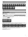
5) Signaux de sortie
Signal entre G-7: 0-4,5 Vdc = 0-débit max. Signal entre G-8: 0-4,5 Vdc = 0-Pa max. Impédance min. = 100 MΩ.
Débit max.
Pres. max.
DD 9-7TH
1/2
720054
2000
630
DD 9-9
1/2
720055
2900
780
DD 10-10
3/4
720056
3800
1050
DD 11-11
1/1
720057
4400
1070
DP 6-6
1/2
720058
2200
450
Débit max.
Pres. max.
DS 11-4
1/2
720062
1900
950
DS 12-5 (K)DF 280-114 (K)DF 280-114
3/4
1/3
1/2
720063
720077
720078
2600
1300
1700
1310
525
575
DP 9-7TH DP 9-7TH
1/1
1/2
720059
720011
3600
3000
630
575
DP 9-9
DS 10-4 TH DS 10-4
1/1
1/3
1/2
720060
720071
720061
5700
1000
1500
900
585
750
6) Schémas de raccordement
Voir annexe 1.
7) Données techniques
Alimentation: 230VAC (entre 208V et 240V) - Frequence : 50/60Hz
Mise à terre: ! OBLIGATOIRE !
Protection éléctrique:
Le moteur est auto-protégé contre les surcharges. Il n'est donc pas nécessaire de prévoir une protection électrique
contre les surcharges. Une simple protection contre les court-circuits suffit et doit être sélectionnée en respectant les
spécifications suivantes :
- pointe à l'enclenchement de 150 A (20A avec PB S) pendant 2 à 4 millisecondes (si disjoncteur : sélectionner une
courbe de déclenchement de type D – pouvoir de coupure 10.000A - AC3). Il est obligatoire d'utiliser la fonction
softstop afin d'éviter cette pointe.
- nous recommandons une protection de classe AM.
Calibre de la protection/moteur
Type
1/3 HP
1/2 HP
3/4 HP
1/1 HP
Calibre
4A
4A
8A
10A
Exemples indicatifs et non exhaustifs de sélection de : a) cartouches fusibles AM (10x38mm), b) disjoncteurs magnétothermiques : courbes de déclenchement D – pouvoir de coupure 10.000 A. (8A inexistant : mettre 10A)
a)
b)
Calibre
Vynckier
Merlin Gérin
Calibre
Legrand
Télémécanique
Huppertz
2A
réf : 099/37202-000
réf : 25111
2A
réf. :130.02
réf. : DF2-CA02
réf. : D440102
4A
réf : 099/37204-000
réf : 25113
4A
réf. :130.04
réf. : DF2-CA04
réf. : D440104
8A
n'existe pas
n'existe pas
8A
réf. :130.08
réf. : DF2-CA08
réf. : D440108
réf : 099/37210-000
réf : 25115
10A
réf. :130.10
réf. : DF2-CA10
réf. : D440110
10A
Classe d'isolation
Thermique : B / Mécanique : IP44 - les connecteurs doivent être placés vers le bas.
Températures ambiantes: -10°C / +55°C
Conformités: approuvé CE – UL
3
n2
Installatie handleiding
(v.01/03)
1) Schema van de kastjes
Vermogensbox TAC2
Controlebox TACn2
1
2
3
4
5
6
7
8
CONTROLE
VERMOGEN
00W_H
MOTOR
L
N
TO FAN BOX
1 2 GG 3 4 5 6 G 7 8
N
NN
RS485
D
DD
SOFTSTOP
RS485
NORMAL
TERMINATION
CLOSED=RUN
OPEN=STOP
230V +
Als de N2 box is op het einde van een
fysische communicatie lijn geinstalleerd,
zet deze jumper in ‘termination’ positie,
anders op ‘normal’ positie laten. Maximum
20 ‘terminations’ per netwerk.
Kabel specificaties : UTP / Cat.5 / 8 wires / Lmax = 100m
Connectors : RJ45
2) Installatie: SAC of NC?
Met de "Stand alone" configuratie kan u ventilator per ventilator instellen. De link PC ↔ Interface ↔ TACn2 box is
slechts tijdelijk. Gebruik het EOLe2_SA programma.
Met de "Permanent netwerk" configuratie kan u een geheel van ventilatoren instellen. De link PC ↔ Interface ↔
TACn2 boxen is meestal permanent, maar kan ook tijdelijk zijn ("Tijdelijk permanent netwerk" - TNC - bijvoorbeeld bij het
gebruik van een modem). Gebruik het EOLe2 programma.
Iedere ventilator in het netwerk moet zijn eigen adres hebben. Dit doet u met de dip-switches 2 tot 8 van de controlebox
(binair systeem).
Bijvoorbeeld: het adres van ventilator ‘100’ = ’X-1100100’ (*).
Het maximale decimale cijfer dat zo kan verkregen worden is 127 = x – 1111111.
Opgelet: in het netwerk mag er geen adres tweemaal gebruikt worden. Dit leidt tot foutmeldingen.
6
5
4
3
2
1
0
(*) 100 = (1 x 2 + 1 x 2 + 0 x 2 + 0 x 2 + 1 x 2 + 0 x 2 + 0 x 2 ) = 01100100
= ( 64 + 32 + 0 + 0 + 4 + 0 + 0 ) = 100
DS2
DS3 DS4
DS5
DS6 DS7
DS8
4
3) Werkingsmode
Mode CA: Constant debiet. Detail: zie Technische informatie ″TACn2 Mode CA″. Aansluitschema: zie bijlage 1- .
Mode LS: Constant debiet aangehouden in functie van een 0/10V signaal. Detail: zie Technische informatie ″TACn2
Mode LS″. Aansluitschema: zie bijlage 1- .
Mode CS: Constant debiet aangehouden om een gegeven 0/10V signaal constant te houden. Detail: zie Technische
informatie ″TACn2 Mode CS″. Aansluitschema: zie bijlage 1- .
Mode CFP: Constant debiet aangehouden om een berekende opgegeven statische druk van de ventilator aan te houden.
Detail: zie Technische informatie ″TACn2 Mode CFP″. Aansluitschema: zie bijlage 1- .
Mode VCS: Constant debiet aangehouden om een opgegeven variabel 0/10V signaal aan te houden, dat op haar beurt
afhankelijk is van een ander 0/10V signaal, en dit volgens een met parameters vastgelegde relatie. Detail: zie Technische
informatie ″TACn2 Mode VCS″. Aansluitschema: zie bijlage 1- .
Mode VCFP: Constant debiet dat fluctueert om een variabele, berekende drukwaarde van de ventilator aan te houden,
waarbij deze zelf afhankelijk is van een 0-10V signaal en dit volgens een parametriseerbare link. Detail: zie Technische
informatie ″TACn2 Mode VCFP″. Aansluitschema: zie bijlage 1- .
De CB TACn2 zijn voor-geprogrammerd in LS mode (0V = Min. debiet, 10V = Max. debiet)
4) Alarm
De TACn2 kast bevat 3 alarm types : (Voorbeelden aansluitingsschema : zie bijlage 1- alarm op drukwijziging
- ventilator-pech alarm
- initialisatie alarmen
).
4.1 Alarm op drukwijziging:
a) Principe:
Waarschuwt wanneer de effectieve statische druk op de ventilator (Pa) een referentiewaarde in het geheugen overschrijdt
(Paref) + een toegelaten afwijking (dPa). Als dit alarm in werking is, dan staat de status van alarm 2 in het programma
EOLe2 / 2_SA op "ON". Het LED2 lampje in de conttrolebox brandt waarbij de transistor die aangesloten is tussen G en 2
als geleider optreedt.
b) Hoe de referentiedruk in het geheugen zetten::
Zie Technische informatie ″TACn2 Alarmen″.
4.2 Ventilator pechalarm:
Dit alarm signaleert een pech van de ventilator. Bij alarm licht LED1 op en geleidt de transistor van de controlekast
tussen de klemmen G en 1.
4.3 Initialisatie alarmen:
Bij het inschakelen van de ventilator kunnen 5 types problemen optreden :
Type
Beschrijving
INIT1
Ventilator van generatie 2 wordt niet herkend door de controlebox
INIT2
Ventilator van generatie 1
INIT3
Er komt geen toerentalsignaal door van de motor
INIT4
Verandering van de gegevens van het N2 circuit
INIT5
Probleem in detectie van de type ventilator
LED 1
6x
4x
5x
1,2,3,9 x
10 x
LED 2
1x
1x
1x
1x
1x
Probeer altijd eerst om de RJ45 kabel opnieuw te bevestigen. Indien het probleem aanhoudt :
In de eerste 2 gevallen (INIT1 en 2) is de controlebox niet aangepast aan het type ventilato. U dient ofwel de
ventilator ofwel de controlebox te vervangen.
Een alarm type INIT3 geeft aan dat er geen toerentalsignaal van de motor komt. Vervang de TAC2 vermogensbox.
Indien het probleem aanhoudt, vervang de RJ45 kabel. Indien het probleem aanhoudt, vervang de controlebox.
Indien het probleem nog steeds aanhoudt, vervang de ventilator.
Een alarm type INIT4 geeft aan dat er zich een wijziging heeft voorgedaan in het geheugen van de controlebox. In
een dergelijk geval moet de controlebox vervangen worden.
Een alarm type INIT5 geeft aan dat er een probleem in de detectie van het type ventilator is. Vervang de
controlebox. Indien het probleem aanhoudt, vervang de ventilator.
5
5) Uitgangssignalen
Signaal tussen G-7: 0-4,5 Vdc = 0–max. debiet. Signaal tussen G-8: 0-4,5 Vdc = 0-Pa max. Min. impedance = 100 MΩ.
Max. debiet
Max. druk
DD 9-7TH
1/2
720054
2000
630
DD 9-9
1/2
720055
2900
780
DD 10-10
3/4
720056
3800
1050
DD 11-11
1/1
720057
4400
1070
DP 6-6
1/2
720058
2200
450
Max. debiet
Max. druk
DS 11-4
1/2
720062
1900
950
DS 12-5 (K)DF 280-114 (K)DF 280-114
3/4
1/3
1/2
720063
720077
720078
2600
1300
1700
1310
525
575
DP 9-7TH DP 9-7TH
1/1
1/2
720059
720011
3600
3000
630
575
DP 9-9
DS 10-4 TH DS 10-4
1/1
1/3
1/2
720060
720071
720061
5700
1000
1500
900
585
750
6) Aansluitingsschema's
Zie bijlage 1.
7) Technische gegevens
Voeding: 230VAC (tussen 208V en 240V) - Frequency : 50/60Hz
Aarding: ! VERPLICHT !
Electrische beveiliging:
De motor is intern beveiligd tegen overbelasting.Het is dus niet nodig een electrische beveiliging tegen overbelasting te
monteren. Een eenvoudige beveiliging tegen kortsluiting is voldoende en deze moet rekening houden met :
- piekstroom van 150 A (20A met PB S) gedurende 2 à 4 milliseconden bij het starten (indien met schakelaar : een
uitschakelcaracteristiek van het type D selecteren - kortsluitvermogen 10.000A - AC3). Het is verplicht de softstop
functie te gebruiken om deze piekstroom te vermijden;
- wij raden een beveiliging classe AM aan.
Kaliber van de beveiliging/motor
Type
1/3 HP
1/2 HP
3/4 HP
1/1 HP
Kaliber
4A
4A
8A
10A
Indicatieve voorbeelden van de selectie van : a) zekeringspatronen AM (10x38mm), b) magneto-thermische schakelaars :
uitschakelcaracteristiek van het type D - kortsluitvermogen 10.000 A (8A bestaat niet : 10A gebruiken).
a)
b)
Kaliber
Legrand
Télémécanique
Huppertz
Kaliber
Vynckier
Merlin Gérin
2A
2A
réf. :130.02
réf. : DF2-CA02
réf. : D440102
réf : 099/37202-000
réf : 25111
réf. :130.04
réf. : DF2-CA04
réf. : D440104
réf : 099/37204-000
réf : 25113
4A
4A
réf. :130.08
réf. : DF2-CA08
réf. : D440108
bestaat niet
bestaat niet
8A
8A
10A
réf. :130.10
réf. : DF2-CA10
réf. : D440110
10A
réf : 099/37210-000
réf : 25115
Isolatieklasse
Thermisch : B / Mechanisch : IP44 - de connectoren moeten naar beneden geplaatst worden.
Omgevingstemperatuur: -10°C / +55°C
Gelijkvormigheid: goedgekeurd CE - UL
6
n2
Installation manual
(v.01/03)
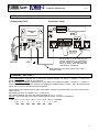
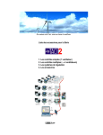
1) Diagram of boxes
TAC2 power box
TACn2 control box
1
2
3
4
5
6
7
8
CONTROL
POWER
00W_H
L
N
TO FAN BOX
1 2 GG 3 4 5 6 G 7 8
NN
N
RS485
DD
D
SOFTSTOP
RS485
NORMAL
TERMINATION
CLOSED=RUN
OPEN=STOP
MOTOR
If the N2 box is installed at the end of a
physical communication line, then put
this jumper in ‘termination’ position, else
let it in the ‘normal’ position. Maximum 20
terminations per network.
230V +
Cable specifications : UTP / Cat.5 / 8 wires / Lmax = 100m
Connectors : RJ45
2) Installation: SAC or NC?
The “Stand alone” configuration (SAC) enables to (re-)configure or to supervise one fan at a time. The PC , Interface ,
TACn2 control box link is temporary. Use the EOLe2_SA software.
The “Network” configuration (NC) enables to (re-)configure or to supervise « on-line » a set of fans. The PC , Interface
, TACn2 control box link is permanent, but can be temporary (for instance when working with a modem). Use the EOLe2
software.
Each fan in the network has to have its own identification – address – this is carried out using dip-switches 2 to 8 and a
binary coding of the desired number.
Example: if address ‘100’ = ’X-1100100’ (*).
Highest allowed number is 127 = ‘x-11111111’
Warning: Be careful not to give the same address to 2 different control boxes. This will create communication problems.
6
5
4
3
2
1
0
(*) 100 = (1 x 2 + 1 x 2 + 0 x 2 + 0 x 2 + 1 x 2 + 0 x 2 + 0 x 2 ) = 01100100
= ( 64 + 32 + 0 + 0 + 4 + 0 + 0 ) = 100
DS2
DS3 DS4
DS5
DS6 DS7
DS8
7
3) Working modes
Mode CA: Constant airflow. Detail: see Technical information ″TACn2 Mode CA″. Wiring diagrams: see appendix 1- .
Mode LS: Constant airflow modulated by a 0-10V signal. Detail: see Technical information ″TACn2 Mode LS″. Wiring
diagrams: see appendix 1- .
Mode CS: Constant airflow modulated with assignement to keep constant a 0-10V sensor value. Detail: see Technical
information ″TACn2 Mode CS″. Wiring diagrams: see appendix 1- .
Mode CFP: Constant airflow modulated with assignement to keep constant a value of the fan’s static pressure. Detail: see
Technical information ″TACn2 Mode CFP″. Wiring diagrams: see appendix 1- .
Mode VCS: Constant airflow modulated with assignement to keep constant a 0-10V sensor value, this value being itself
under the control of another 0-10V signal according to a programmable link. Detail: see Technical information ″TACn2
Mode VCS″. Wiring diagrams: see appendix 1- .
Mode VCFP: Constant airflow modulated with assignement to keep constant a value of the fan’s static pressure, itself
being determined by an external 0-10V sensor signal according to a programmable link. Detail: zie Technische informatie
″TACn2 Mode VCFP″. Wiring diagrams: see appendix 1- .
The CB TACn2 are pre-programmed in LS mode (0V = Min. airflow, 10V = Max. airflow).
4) Alarm
The TACn2 allows 3 types of alarms: (Examples of wiring diagram: see appendix 1- Pressure variation alarm
- Motor failure alarm
- Initialization alarms
).
4.1 Pressure rise alarm:
a) Principle:
Warn when the actual static pressure on the fan (Pa) overrides a pre-determined reference value (Paref) + a predetermined pressure variation (dPa=’offset’). When triggered, LED2 is lit, the transistor connected between terminals G
and 2 (see wiring) is conductive, and the ‘status’ of ‘alarm2’ is ‘ON’ in the EOLe2 / 2_SA software.
b) Memorizing ‘reference pressure’ and ‘offset’:
see Technical information ″TACn2 alarms″.
4.2 Motor failure alarm:
This warning signals automatically a motor failure. When activated, LED1 is lit and the transistor between G and 1 on the
control board is conductive.
4.3 Initialization alarm:
When you set the power ON, 5 kinds of problem can occur :
Type
Description
INIT1
Generation2 fan not recognized by TAC2 control box
INIT2
First generation motor program
INIT3
No RPM feedback from the motor
INIT4
Data damage in N2 control box
INIT5
Problem in detection of the fan type
LED 1
6x
4x
5x
1,2,3,9 x
10 x
LED 2
1x
1x
1x
1x
1x
First, always unplug/replug the RJ45 connector. And if the problem persists :
In case of INIT 1 or 2, the control box is not adapted to the motor program. Either replace the control box or the fan
whatever is the most suitable solution.
INIT3 alarm means no rpm feedback from the motor. Replace the power box. If the problem persists, replace the
RJ45 cable. If the problem persists, replace the control box. If the problem still persists, replace the fan.
INIT4 alarm means data in the memory is damaged. The control box must be replaced.
INIT5 alarm means there is a problem to detect the fan type. Replace the control box. If the problem persists,
replace the fan.
8
5) Feedback signals
Signal between G-7: 0 - 4,5 Vdc = 0-max. airflow. Between G-8: 0 - 4,5 Vdc = 0-Pa max. Min. impedance = 100 MΩ.
Max. airflow
Max. pres.
DD 9-7TH
1/2
720054
2000
630
DD 9-9
1/2
720055
2900
780
DD 10-10
3/4
720056
3800
1050
DD 11-11
1/1
720057
4400
1070
DP 6-6
1/2
720058
2200
450
Max. airflow
Max. pres.
DS 11-4
1/2
720062
1900
950
DS 12-5 (K)DF 280-114 (K)DF 280-114
3/4
1/3
1/2
720063
720077
720078
2600
1300
1700
1310
525
575
DP 9-7TH DP 9-7TH
1/1
1/2
720059
720011
3600
3000
630
575
DP 9-9
DS 10-4 TH DS 10-4
1/1
1/3
1/2
720060
720071
720061
5700
1000
1500
900
585
750
6) Wiring diagrams
See appendix 1.
7) Technical data
Supply : 230VAC (between 208V and 240V) - Frequency : 50/60Hz
Grounding : ! COMPULSORY !
Electrical protection :
The motor is self-protected against overloading. It is thus NOT necessary to install an electrical overload protection
device. We advise using a short circuit protection device with the following specifications :
- Starting peak of 150 A (20A using a PB S) for 2 to 4 milliseconds. The “softstop” function has to be used to avoid
this peak.
- We recommend a class AM protection device.
Recommended protection calibre/motor type
Type
1/3 HP
1/2 HP
3/4 HP
1/1 HP
Calibre
4A
4A
8A
10A
Indicative non exhaustive list of : a) AM (10x38mm) fuses with manufacturers references, b) references of thermo
magnetic circuit breakers (disjoncteur): select it with D type “slow” reaction curve – cutting power of 10.000A - AC3.
a)
b)
Calibre
Legrand
Télémécanique
Huppertz
Calibre
Vynckier
Merlin Gérin
2A
réf. :130.02
réf. : DF2-CA02
réf. : D440102
2A
réf : 099/37202-000
réf : 25111
4A
réf. :130.04
réf. : DF2-CA04
réf. : D440104
4A
réf : 099/37204-000
réf : 25113
8A
réf. :130.08
réf. : DF2-CA08
réf. : D440108
8A
does not exist
does not exist
réf. :130.10
réf. : DF2-CA10
réf. : D440110
réf : 099/37210-000
réf : 25115
10A
10A
Insulation class
Thermal : B / Mechanical : IP44 - the connectors must be oriented downwards.
Ambiant temperatures : -10°C / +55°C
Conformities : CE – UL approved
9
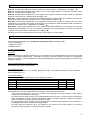
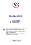
ANNEXE 1 – BIJLAGE 1 – APPENDIX 1
Schémas de raccordement / Aansluitingsschema's / Wiring diagrams
Puissance/Vermogen/Power .
CONTROL
POWER
La borne de terre doit toujours être raccordée.
L
De aarding moet altijd aangesloten worden.
N
The fan must always be grounded.
MOTOR
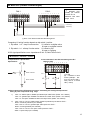
Mode CA .
Wiring 1 : one airflow + softstop
FAN 2
FAN 1
1
2
G
G
3
4
5
6
G
7
8
1
2
G
G
3
4
5
6
G
7
8
Maximum fans
quantity per external
contacts set : 20
Maximum total cable
length: 100 m.
Closed = ON
Open = softstop
Wiring 2 : 3 airflows + softstop with 2 external contacts
FAN 2
FAN 1
1
2
G
G
3
4
5
6
G
7
8
1
2
G
G
3
4
5
6
G
7
8
Maximum fans
quantity per external
contacts set : 20
Maximum total cable
length: 100 m.
K1
K2
K1
K2
M
Closed Open
100%
Closed Closed
X2%
Open
Closed
X1%
Open
Open Softstop
10
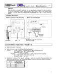
Wiring 3 : 3 airflows + softstop with EDS4
FAN 1
1
2
G
G
3
4
5
6
G
7
8
1
2
G
G
3
4
5
6
G
7
8
Maximum fans
quantity per external
contacts set : 20
Maximum total cable
length: 100 m.
Pos
III
II
I
0
EDS4
K2
A
airflow
100%
X2%
X1%
softstop
K1 24V
B C
Mode LS / Mode CS / Mode VCFP
FAN 2
FAN 1
1
2
G
G
3
4
5
6
G
7
8
1
2
G
G
3
4
5
6
G
7
8
Maximum fans
quantity per external
contacts set : 20
Maximum total cable
length: 100 m.
0-10V IN
K3
K1
- K1 = compulsory wiring of the softstop/softstart feature (closed=on, open=off )
- K3 = optional wiring of the ‘sleep’ function. Multiplier is activated when contact closed.
- 0/10V signal specifications: max. Impedance=30 kΩ - 0,03mA/TACn2 circuit.
Mode CFP (Constant Fan Pressure)
FAN 2
FAN 1
1
2
G
G
3
4
5
6
G
7
8
1
2
G
G
3
4
5
6
G
7
8
Maximum fans
quantity per external
contacts set : 20
Maximum total cable
length: 100 m.
K1
K3
- K1 = Compulsory softstop/softstart wiring (closed=ON, open=softstop)
- K3 = Optional ‘sleep’ function. Multiplier activated if contact closed.
11
Mode VCS (Variable Constant Signal)
FAN 2
FAN 1
1
2
G
G
3
4
5
6
G
7
8
1
2
G
G
3
4
5
6
G
7
Maximum fans
quantity per external
contacts set : 20
8
Maximum total cable
length: 100 m.
0-10V IN (*)
0-10V IN (*)
K1
(*) the 2 0-10V sensors must have the same ground
Compulsory K1 wiring function depends on dip-switch 1 position :
1. Dip-switch 1 = 0 : ‘sleep’ function active:
K1 closed " multiplier active
K1 open " multiplier inactive
2. Dip-switch 1 = 1 ‘softstop’ function active: K1 closed " ON
K1 open " Softstop
0/10V signal specifications: max. Impedance=30 kΩ - 0,03mA/TACn2 circuit.
Alarmes / Alarmen / Alarms .
6.1 Spécifications / Specificaties /
Specifications
6.2 Raccordement à des LED / Aansluiting aan LED /
Wiring to LED
1
1 or 2
Vmax = 25 Vdc
Imax = 50 mA
2
G
G
3
4
5
6
G
7
8
Alarm 2
Alarm 1
(4 )= LED
(5) = resistance to limit
current (example : 4K7
for a low current LED (≈
2mA) 1K0 for a normal
LED (≈ 10mA)
G
6.3 Raccordement à des éléments de puissance / Aansluiting aan vermogenscomponenten /
Wiring to power components using relays
1)
Imax = 1A: utiliser l’option ‘’Satellite pour alarmes par relais TAC2’’ (SAR2 - cid = 005012)
Imax = 1A: gebruikt optie ‘’Satelliet voor alarmen door relais TAC2’’ (SAR2 - cid = 005012)
Imax = 1A: use option ‘’Satellite for alarms via relays TAC2’’ (SAR2 - cid = 005012)
2)
Imax = 10A AC1 / 5A AC3: utiliser l’option ‘’Boîtier de puissance pour alarmes TAC2’’ :
APB2 = 2 relais de puissance (cid = 005065)
Imax = 10A AC1 / 5A AC3: gebruikt optie ‘’Alarm power box TAC2’’ :
APB2 = 2 vermogensrelais (cid = 005065)
Imax = 10A AC1 / 5A AC3: use option ‘’Alarm power box TAC2’’ :
APB2 = 2 power relays (cid = 005065)
12