1
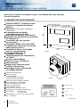
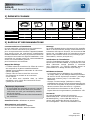
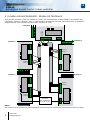
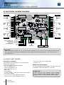
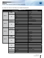
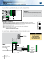
FR FRANCAIS
* Voir conditions de garantie à vie limitée. / Refer to Limited Lifetime Warranty.
EN ENGLISH
DGM4D
KIT DGM4D
TDG4D
Centrale Mifare® 4 portes
4-Door contactless smart card unit
Range: Integrated Access Control / Gamme: Contrôle d’accès intégré
INSTALLATION MANUAL
MANUEL D’INSTALLATION
Group Products
INSTALLATION MANUAL
FR
DGM4D
Smart Card Access Control 4 door controller
Merci pour l’achat de ce produit et pour la confiance que vous accordez
à notre entreprise.
1] PRESENTATION DU PRODUIT
Conforme Mifare® (système ouvert
à toutes les marques de badges Mifare®).
Tête TDG4 : Très haute résistance
à la flamme.
Programmation de badge
sans déplacement sur site.
Historique de passage (Résidents).
Système autonome (pas de connexion PC nécessaire).
5 centrales par site (gestion
de 20 portes).
Compatible DGM1 via le PCV123D
(uniquement à partir de la centrale
DGM1 Version 3.0.0.).
Possibilité d’effacer les badges
pour les reprogrammer.
Programmation sans fil
de badges résidents.
Téléchargement des informations
via TDG4.
Borniers débrochables.
Gestion horaire (résidents).
Anti-passback.
Badges avec indice de perte
et accès hiérarchisés.
80 badges passes (240 portes
par badges passes).
Centrale lecture/Ecriture.
Gestion 4 portes :
- 4 relais NO/NF,
- 4 entrées bouton poussoir,
- jusqu’à 4 têtes de lecture.
Gestion de 20000 badges résidents.
Droits utilisateurs sur le badge.
3000 évènements mémorisés.
Fonction anti-passback.
1 sortie NO/NF alarme :
Porte forcée ou restée ouverte.
Remplacement du badge automatique.
Free voltage* : - 12 à 40 V DC
- 12 à 28 V AC.
Consommation : En 12 V DC, 500 mA max. (Têtes + centrale).
140
180
DGM4D
65
61
41
TDG4D
Alimentations
préconisées
49
DEEE & RoHS
Certification CE
IP52
ARD12
BS60
-20°C à +70°C
* Tension libre
22
cdvi.com
cdvigroup.com
INSTALLATION MANUAL
FR
DGM4D
Smart Card Access Control 4 door controller
2] éléments fournis
Ecrou T25
Cable DGM4D
Varistance
DGM4D
TDG4D
DGM4D
-
-
1
1
-
Kit DGM4D
1
1
1
1
1
TDG4D
1
-
1
-
1
3] RAPPELS ET RECOMMANDATIONS
recommandations d’installation
Un soin particulier a été pris avec les instructions
afin de le rendre aussi facile que possible
pour vous permettre de connecter l’appareil DGM4D.
Vous devez suivre les instructions complètement
DGM4D installation de l’unité, en particulier toutes les
remarques concernant les règles d’installation. C’est
seulement en suivant toutes les recommandations
citées est l’unité DGM4D garantie
pour fonctionner correctement.
Rappel de câblage
- Le câble reliant la Centrale et les Têtes de Lecture est composé de 2 paires torsadées blindées 24AWG d’une Impédance Nominale de 120 ohms (Norme EIA-485).
- Chaque Tête de Lecture doit être au moins
à 2 mètres de la centrale et au maximum
à 100 mètres.
- Si les têtes sont montées dans un boîtier
métallique, celui-ci doit être raccordé à l’écran (masse) de la centrale.
Remarque importante :
- Si votre câble est composé de plus de 2 paires,
ne pas laissez les fils du câble sans potentiel,
c’est à dire non relié, par conséquent, doublez
les fils de la paire.
- Le sens de branchement des 2 fils d’alimentation
est indifférent.
Contrôle d’accès : Résidents et passes.
Montage
La centrale DGM4D doit exclusivement être installée
dans un environnement protégé conformément aux
indications décrivant le niveau 2, de la norme NF EN
61000-4-4. Les câbles reliés à la centrale ne doivent
pas être à proximité d’autres sources d’énergie (Ex. :
alimentation, secteur principal etc.).
Vérification de l’installation
Une fois l’installation terminée, lors de la mise sous
tension de la centrale DGM4D, le voyant de la ou des
têtes s’allument orange pendant 5 secondes
puis s’éteignent. La centrale DGM4D attend la
présentation d’un badge devant la/les tête(s).
Résidents et Passes
- La Centrale gère les Résidents (qui possèdent
un badge CDVI) et des badges Passes permettant
de donner l’accès à plusieurs centrales. (Un badge
Passe peut contenir jusqu’ à 12 codes sites différents).
- Chaque nouveau Badge (Résident ou Passe),
préalablement chargé, est ajouté automatiquement
à la liste de la Centrale à sa première présentation
devant une des Têtes de Lecture. La gestion
des Résidents et des Passes se fait à l’aide du
logiciel PC et du Programmateur portable PCV 123.
Norme CE
La centrale DGM4D répond à la directive
R&TTE1999/5/CE : norme de sécurité électrique
EN 60950(2000), norme CEM EN 50130-4,
norme radio appliquée EN 300 330-2(2001).
N° homologation : 22033-0 RGV-SP5907-V2.0
Alimentations préconisées
Il existe deux alimentations adaptées
pour la centrale DGM4D: ARD12 et BS60.
cdvi.com
cdvigroup.com
33
INSTALLATION MANUAL
FR
DGM4D
Smart Card Access Control 4 door controller
4] SCHÉMA DE RACCORDEMENTS
1
RS232 link
(to programmer)
J7
1
1
J8
J2
JP5
J4
J10
1
1
JP4
JP7
1
+
J11
JP2
1
JP1
JP1
-
+
J3
1
J9
1
RS 485 A
RS 485 B
RS 232 TX
RS 232 RX
GND
Ecran
J13
J12
+
Door 2
Inter-controller link
(Networking)
BP
Door contact
GND
Tx/Rx A
Reader
Tx/Rx B
head
+12V
link
GND
Screen
JP6
1
BP
Door contact
GND
Tx/Rx A
Reader
Tx/Rx B
head
+12V
link
GND
Screen
NO
C
NF
JP3
J5
NO
C
RL2
1
1
RL3
BP
Door contact
GND
Tx/Rx A
Reader
Tx/Rx B
head
+12V
link
GND
Screen
1
Door contact
GND
Tx/Rx A
Reader
Tx/Rx B
head
+12V
link
GND
Screen
NO
C
NF
1
1
RL1
Door 3
J1
NO
C
NF
J6
1
Door 1
RL4
Door 4
NO
C
NF
Alarm exit
Input voltage
Ground
Important :
- Les connecteurs J1, J2, J4 et J5 ainsi que les connecteurs J7, J8, J10 et J11 ont un câblage indépendant.
- Il est conseillé de connecter les têtes TDG4 à la centrale DGM4D progressivement de la porte 1 à 4.
A] Câblage de la centrale DGM4D
Connecteurs de la centrale
Pour mettre en service la centrale vous devez
au minimum relier les connecteurs :
- Bouton Poussoir de Sortie et Contact
de Porte (J2, J5, J8 et J11),
- Liaison vers Programmateur : J3,
- Alarme : J9,
- Consommation :
(70 mA / tête) – (100 mA / tête + relais collé).
- J12 : Alimentation
- J1 ou J4 ou J7 ou J10 : Commande d’ouverture
(gâche électrique, ventouse, …)
- J2 ou J5 ou J8 ou J11 : Tête de Lecture
44
cdvi.com
cdvigroup.com
- Terre : J13
Alimentation de la centrale DGM4D
La tension d’alimentation peut être comprise entre
12 et 40 Volts DC ou entre 12 et 28 Volts AC / 500
mA.
Important :
L’alimentation des commandes d’ouverture (gâches
électriques, ventouses…) et l’alimentation de la
centrale doivent avoir des alimentations séparées.
INSTALLATION MANUAL
FR
DGM4D
Smart Card Access Control 4 door controller
B] Tableaux de correspondance de la centrale DGM4D
DGM4D Porte de 1 à 4
Bornier
J1
[Relay 1]
Door 1
J2
J4
[ Relay 2]
Door 2
J5
J7
[Relay 3]
Door 3
J8
J10
[Relay 4]
Door 4
J11
J3
J9
J12
J13
Correspondance
NO
C
NF
BP
Contact de porte
GND
Tx/Rx A
Tx/Rx B
+12V
GND
Ecran
Contact relais normalement ouvert
Commun relais
Contact relais normalement fermé
Bouton poussoir
NO
C
NF
BP
Contact de porte
GND
Tx/Rx A
Tx/Rx B
+12V
GND
Ecran
Contact relais normalement ouvert
Commun relais
Contact relais normalement fermé
Bouton poussoir
NO
C
NF
BP
Contact de porte
GND
Tx/Rx A
Tx/Rx B
+12V
GND
Ecran
Contact relais normalement ouvert
Commun relais
Contact relais normalement fermé
Bouton poussoir
NO
C
NF
BP
Contact de porte
GND
Tx/Rx A
Tx/Rx B
+12V
GND
Ecran
Contact relais normalement ouvert
Commun relais
Contact relais normalement fermé
Bouton poussoir
RS 485 A
RS 485 B
RS 232 TX
RS 232 RX
GND
Ecran
NO
C
NF
Alimentation
Alimentation
Terre
Terre
Liaison inter-centrale (Réseau)
Liaison inter-centrale (Réseau)
Liaison RS232 (vers programmateur)
Liaison RS232 (vers programmateur)
Masse
Ecran
Contact relais normalement ouvert
Commun relais
Contact relais normalement fermé
12-40V DC - 12-28V AC
12-40V DC - 12-28V AC
Masse
Liaison
Liaison
Liaison
Liaison
Ecran
Masse
Liaison
Liaison
Liaison
Liaison
Ecran
Masse
Liaison
Liaison
Liaison
Liaison
Ecran
Liaison
Liaison
Liaison
Liaison
Masse
Ecran
tête
tête
tête
tête
tête
tête
tête
tête
tête
tête
tête
tête
tête
tête
tête
tête
de
de
de
de
de
de
de
de
de
de
de
de
de
de
de
de
lecture
lecture
lecture
lecture
lecture
lecture
lecture
lecture
lecture
lecture
lecture
lecture
lecture
lecture
lecture
lecture
cdvi.com
cdvigroup.com
55
INSTALLATION MANUAL
FR
1
J10
1
DGM4D
Smart Card Access Control 4 door controller
C ] ELECTRICAL WIRING DIAGRAM: EARTH CONNECTION
JP7
1
1
GND
Important :
Si vous n’êtes pas certain de la qualité de
votre terre ou si vous ne disposez pas d’un
fil de terre, reliez directement le connecteur
terre au GND via un fil électrique comme
illustré dans le schéma suivant.
J11
Tx/Rx A
Tx/Rx B
+12V
Ground
1
Ecran
J13
J12
1
1
Terre
Description des Jumpers :
- JP1/JP2 > Activation des résistances terminales de la liaison RS485 (Inter centrales).
- JP3 > Jumper d’autorisation de mise à jour logicielle.
- JP4 > NC
- JP5 > Réservé pour une utilisation future.
- JP6 > Active la liaison RS232 et permet la modification du Code Site de la centrale.
- JP7 > Choix de la tension d’alimentation des relais :
- Position 1 (Plus de 18 V AC/DC),
- Position 2 (Moins de 18 V AC/DC).
Position 1
Position 2
J1
J2 or J5
J8 or J11
Paire torsadée
Ecran à raccorder
au boîtier métallique
Tx/Rx A
Tx/Rx B
+12V
Ground (Masse)
Ecran
Paire torsadée
cdvi.com
cdvigroup.com
Les connecteurs de droites
(J1, J2, J4, J5) et les
connecteurs de gauche
(J7, J8, J10, J11) n’ont
pas pas les mêmes
raccordements
1
TDG4D
6
Connecteur
de raccordement
de l’antenne
Tx/Rx A
Tx/Rx B
+12V
Ground
J2
1
D] SCHÉMA DE RACCORDEMENTS DE LA TÊTE DE LECTURE TDG4D
DGM4D
INSTALLATION MANUAL
FR
DGM4D
Smart Card Access Control 4 door controller
E ] SCHÉMA DE RACCORDEMENTS DES boutons poussoirS
Les boutons poussoir de sortie sont connectés aux bornes de la centrale sur les connecteurs J2, J5, J8 et J11.
Boutons poussoirs
Ground
J2 ou J5
J8 ou J11
Raccordement de la commande d’ouverture :
- La commande de porte se fait par contact sec aux bornes du relais de la centrale
sur les connecteurs J1, J4, J7 et J10.
- La commande d’ouverture est maintenue pendant 5 secondes par défaut.
- La temporisation de porte est modifiable de 2 à 20 secondes à l’aide du programmateur.
- La temporisation est la même pour toutes les portes de la centrale.
Ce produit est livré avec une varistance :
Celle-ci doit être montée directement sur les bornes de la gâche (ventouse, moteur, …)
commandée par l’équipement. La varistance limite les surtensions provoquées
par le bobinage de la gâche – effet de self.
F ] SCHÉMA DE RACCORDEMENTS DES CONTACTS DE PORTE
Les contacts de porte sont connectés aux bornes de la centrale sur les connecteurs J2, J5, J8 et J11.
Ils permettent de déterminer si la porte est ouverte ou fermée.
Contacts de porte
Ground
J2 ou J5
J8 ou J11
cdvi.com
cdvigroup.com
77
INSTALLATION MANUAL
FR
DGM4D
Smart Card Access Control 4 door controller
G ] Schéma de raccordement : Réseau de centrales
Vous pouvez connecter jusqu’à 5 centrale en réseau par l’intermédiaire du BUS RS485. Les centrales sont
connectées, comme ci-dessous, avec un cable blindé et torsadé de 120 ohm (Norm EIS-485). la distance à
respectée entre deux centrales se situe entre 2 mètres et 1 km.
Centrale 3
JP2
RS485 A
RS485 B
JP1
Centrale 3
Centrale 2
RS485 A
JP2
RS485 B
JP1
JP1
JP2
RS485 B
RS485 A
Centrale 1
Centrale 4
JP2
RS485 A
RS485 B
JP1
JP1
RS485 B
RS485 A
Activation
des résistances
de fin de boucle
Notes :
Les cavaliers JP1 et JP2 doivent être positionnés exclusivement sur la première et dernière centrale du réseau.
88
cdvi.com
cdvigroup.com
INSTALLATION MANUAL
FR
DGM4D
Smart Card Access Control 4 door controller
Journal des évènements
- Chaque centrale enregistre l’ensemble
des évènements de ses portes. Vous pouvez ainsi
récupérer vos rapports d’évènements à partir de
l’une des 4 têtes de lecture TDG4D de la centrale.
- Lorsque vous entrer un « Nouveau code site »,
vos évènements sont effacés ainsi que la totalité
des indices de perte (résidents et passes).
- Pour que les évènements soient de nouveau pris
en compte, il faut reconfigurer la centrale
ou le site de centrales.
Mise à la l’heure de la centrale
- La mise à l’heure de la centrale DGM4D est réalisée
en usine.
- Si vous enlevez ou remplacez la pile, il faut le faire
centrale sous tension (Référence de la pile
au lithium : CR2032). Vérifier et ou remettre
l’heure et la date à l’aide du programmateur
portable PCV123D.
- La date par défaut est 01/01/1998.
- L’heure par défaut est 00:00.
Notes : Si vous enlevez ou remplacez la pile,
centrale hors tension, l’heure et la date sont
perdues. Il faut alors remettre l’heure et la date
à l’aide du programmateur portable : PCV123D
(centrale sous tension).
Mise à jour de la centrale DGM4D
- Se reporter à la Notice de mise à jour du logiciel
de la Centrale DGM4D.
- Mise en garde spéciale :
les gestionnaires d’immeubles doivent
s’assurer que la personne intervenant pour la mise
à jour du logiciel est autorisée à le faire.
Que faire en cas de perte du code site
et/ou du mot de passe de votre centrale
DGM4D ?
1 - Mettez la DGM4D hors tension,
2 - Otez la pile,
3 - Attendez quelques secondes (la date s’initialise
au 01/01/98),
4 - Connectez la DGM4D au PCV123D avec la liaison
RS232,
5 - Replacez la pile,
6 - Sur le PCV123D, entrez le code site “0”
et le mot de passe “0 0 0 0”,
7 - Le PCV123D affiche alors” Code site incorrect”
ou “Mot de passe incorrect”, suivi d’une chaîne
de décryptage,
8 - Communiquez cette chaîne de décryptage
à votre fournisseur en lui spécifiant que la date
a été initialisée au 01/01/1998.
9 - Votre fournisseur vous fournira en retour le code
site et le mot de passe de votre centrale.
NB : N’oubliez pas de remettre votre DGM4D à
l’heure avec le PCV123D.
Mise sous tension et vérification
de l’installation DGM4D
- A la mise sous tension de la centrale : la led
de la DGM4D reste allumée pendant toute sa
phase d’initialisation. Il est impératif d’avoir
au moins une tête TDG4D reliée à la centrale
pour que l’étape d’initialisation se passe
correctement. Dans le cas contraire, le relais
de l’alarme est activé et désactivé 4 fois de suite
et la centrale reste en phase d’initialisation.
Le relais de l’alarme continue d’être activé
et désactivé 4 fois de suite tant que la centrale
DGM4D ne détecte pas la présence d’au moins
une tête TDG4D.
- Lorsque la centrale est correctement initialisée,
c’est à dire lorsqu’elle a détecté la présence
d’une tête TDG4D, l’étape d’initialisation
est terminée.
- La led de la centrale clignote lentement
(environ toutes les secondes).
- A la mise sous tension de la centrale DGM4D,
le voyant de chaque tête TDG4D s’allume en
orange.
- Si la TDG4D affiche un voyant rouge, l’initialisation
est incorrecte.
- Une fois que la tête TDG4D a été reconnue
et correctement initialisée, le voyant s’éteint.
Notes : Si le voyant ne s’allume pas ou si il est
toujours allumé après plus de 10 secondes,
la tête TDG4D est en défaut. (Vérifier le câblage
à nouveau).
- Lorsque la centrale fonctionne et qu’elle détecte
une non cohérence de l’un des paramètres
programmés dans le badge résident ou passe,
le voyant de la tête TDG4D envoie un signal lumineux
correspondant au problème détecté :
Clignotement vert rapide
Lecture du badge
Vert fixe 10 secs
Ouverture de la porte
Clignotement rouge rapide
10 secs
Code site erroné ou paramètre*
incorrect dans le badge
Clignotement rouge lent
10 secs
Badge non compatible
DGM4D ou badge vierge
*Paramètres incorrects dans le badge :
- Début de validité non valide - Fin de validité non valide
- Indice de perte non valide - Plages horaires non valides
- Jours autorisés non valides - Mois autorisés non valides
- Portes autorisées non valides - Mode anti-passback activé
cdvi.com
cdvigroup.com
99
INSTALLATION MANUAL
DGM4D
Smart Card Access Control 4 door controller
FR
5] GARANTIE À VIE [EXTRAIT]*
Les sociétés CDVI garantissent que ce produit est dépourvu de tout vice caché, tant dans les matériaux
que dans sa fabrication, à la condition, qu’il soit installé conformément aux préconisations du fabricant
et qu’il n’y ait pas eu d’interventions ou de modifications sur le produit. La responsabilité de CDVI se limite
à la réparation ou à l’échange du produit. CDVI n’assume aucune responsabilité concernant les dommages sur
les biens ou les personnes. Un produit reconnu défectueux par CDVI doit être retourné au service-après-vente
de CDVI, après l’obtention du numéro d’autorisation de Retour de Produit(s) Défectueux (RMA). La responsabilité
de CDVI se limite à la réparation ou au remplacement d’un produit ou pièces défectueuses, en ses ateliers.
L’une ou l’autre de ces interventions sont définis par le service-après-vente de CDVI. Le préjudice imputable
à CDVI ne saurait en aucun cas dépasser la valeur du produit. La responsabilité de CDVI ne peut être engagée
auprès de l’acheteur, installateur, client final ou qui que ce soit, lors de dommages consécutifs à des imperfections
ou mauvais fonctionnement du produit. Cette garantie prend effet à la date d’enregistrement du produit
auprès de CDVI, à partir de l’instant ou la date d’enregistrement est dûment complétée, dans la limite
d’un mois, après la date de livraison au client final. Pour obtenir les détails complets de cette garantie
et enregistrer votre/vos produit(s) pour bénéficier de cette « Garantie à Vie limitée ». Veuillez compléter
la carte d’enregistrement présente dans la boite du produit et nous la retourner, par email ou par courrier,
à l’adresse de l’entité CDVI la plus proche ou vous enregistrer en ligne à l’adresse www.cdvigroup.com.
Les contacts des entités CDVI sont accessibles en ligne à l’adresse www.cdvigroup.com ou au dos de la notice
d’installation.
EXCLUSIONS DE LA GARANTIE : A l’EXCEPTION DES POINTS EVOQUES PRECEDEMMENT, CDVI
N’APPLIQUE AUCUNE GARANTIE, NI DELIBEREE NI TACITE, A TOUS LES PROBLEMES INCLUANT
LE CONDITIONNEMENT, LE TRANSPORT, LEUR COMMERCIALISATION OU LES CONDITIONS D’UTILISATIONS
PARTICULIÈRES.
6] NOTES
* Voir les conditions de garantie à vie limitée complètes sur le site cdvigroup.com.
10
10
cdvi.com
cdvigroup.com
INSTALLATION MANUAL
FR
DGM4D
Smart Card Access Control 4 door controller
cdvi.com
cdvigroup.com
11
11
INSTALLATION MANUAL
EN
DGM4D
Smart Card Access Control 4 door controller
Thank you for buying our products and for the confidence you placed
in our company.
1] PRODUCT PRESENTATION
Mifare® compliant (system open
to all brands of Mifare® tags.).
TDG4D reader: Very highly flame-resistant.
Tag programming without changing
location on site.
Residents passage log.
Stand alone system
140
(no PC connection necessary).
5-controller network (manages
20 doors) on one RS485 bus.
DGM4D compatible via the PCV123D.
Tags can be erased for reprogramming.
Wireless programming of resident tags.
Information downloadable via TDG4D reader.
Snap-off terminal blocks.
Schedules.
Anti-passback.
Badges with loss index and level access.
80 pass tags (240 doors per pass tag).
Read/write unit.
4-door controller:
- 4 NO/NC outputs,
- 4 exit button inputs,
- Up to 4 reader.
Management of 20000 resident tags.
User rights on the tag.
3000 events in buffer memory.
Anti-passback feature.
1 NO/NC alarm exit: door forced
or stayed open.
Held open tag replacement.
Free voltage: 12 to 40V dc or 12 to 28V ac.
Consumption: at 12V dc, 500 mA max.
(reader + controller).
180
DGM4D
65
61
41
TDG4D
49
Recommended
power supplies
WEEE & RoHS
CE Certification
IP52
ARD12
12
12
cdvi.com
cdvigroup.com
BS60
-20°C to +70°C
INSTALLATION MANUAL
EN
DGM4D
Smart Card Access Control 4 door controller
2] MOUNTING KIT
T25 lock-nut
DGM4D Cable
Varistor
DGM4D
TDG4D
DGM4D
-
-
1
1
-
Kit DGM4D
1
1
1
1
1
TDG4D
1
-
1
-
1
3] REMINDERS AND RECOMMENDATIONS
Installation recommendations
Particular care was taken with the instructions
in order to make it as easy as possible
for you to connect the DGM4D unit. You must
completely follow the DGM4D unit installation
instructions, in particular all remarks concerning
installation rules. Only by following all the cited
recommendations is the DGM4D unit guaranteed
to function properly.
Cabling
Notes : The 2 power cables can be connected
in either direction.
-The cable connecting the Controller and the Reader
heads has two 24AWG shielded twisted pairs with
a Nominal Impedance of 120 ohms (Norm EIA-485).
-Each Reader Head must be a minimum of 2 meters
and a maximum of 100 meters from the controller
(in compliance with general smart card access
control regulations).
- If the heads are mounted in a metal box, it must
be connected to the controller screen (earth).
- Not respecting this distance or the connection
means it will not be compliant with the smart card
access control standard.
Important:
- If your cable has more than 2 pairs,
do not leave the wires of the cable without potential,
in other words unconnected («in cut ends»).
- To avoid this, double up on the connections.
Recommended input voltage
There are two input voltages adapted for the
DGM4D: ARD12, BS60 or PSU12.
Mounting
The DGM4D controller must only be installed in a
protected environment in accordance with the instructions
describing level 2, of the NF EN 61000-4-4 norm. The
cables connected to the controller must not carry other
sources of energy (e.g.: input voltage, mains, etc.).
Verifying the installation
Once the installation has been completed, when
the DGM4D controller is turned on, the indicator
light for the heads turns orange for 5 seconds then
goes off The DGM4D controller waits for a tag to be
presented to the reader head(s).
Smart Card Access Control
This system equally manages residents and/or
groups (clubs & associations) with the use of the
PCV123 (not included with the DGM4D).
Residents and Master badge
-The Controller manages the Residents (who have
a CDVI tag) and Pass tags for access to several
controllers, even when not connected to the
network. A Pass tag can contain up to 12 different
site codes).
-Each new Tag (Resident or Master badge), previously
loaded, is automatically added to the Controller
list the first time it is presented to one of the Read
Heads. Residents and Passes are managed using the
PC software and the PCV 123 handheld terminal unit.
CE standard
The DGM4D controller is compliant with directive
R&TTE1999/5/CE: electrical safety norm EN
60950(2000), norm CEM EN 50130-4, applied RF
norm EN 300 330-2(2001).
cdvi.com
cdvigroup.com
13
13
INSTALLATION MANUAL
EN
DGM4D
Smart Card Access Control 4 door controller
4] ELECTRICAL WIRING DIAGRAM
1
1
NO
C
NC
RS232 link
(to programmer)
1
1
1
1
J8
J2
J4
J10
1
JP4
JP7
1
J11
1
+
JP2
-
+
J3
1
J9
1
RS 485 A
RS 485 B
RS 232 TX
RS 232 RX
GND
Ecran
J13
J12
+
Door 2
Inter-controller link
(Networking)
BP
Door contact
GND
Tx/Rx A
Reader
Tx/Rx B
head
+12V
link
GND
Screen
JP5
JP1
JP1
1
RL3
NO
C
NC
JP6
1
BP
Door contact
GND
Tx/Rx A
Reader
Tx/Rx B
head
+12V
link
GND
Screen
NO
C
NC
BP
Door contact
GND
Tx/Rx A
Reader
Tx/Rx B
head
+12V
link
GND
Screen
JP3
J5
RL2
Door 3
J7
1
BP
Door contact
GND
Tx/Rx A
Reader
Tx/Rx B
head
+12V
link
GND
Screen
RL1
J6
J1
NO
C
NC
1
Door 1
1
RL4
Door 4
NO
C
NF
Alarm exit
Input voltage
Ground
Important:
- Note! The right connectors (J1, J2, J4, J5) and left connectors (J7, J8, J10, J11) do not have the same wiring.
- We recommend connecting the TDG4 heads to the DGM4 unit by starting with Door 1, then Door 2, Door 3
and finally Door 4.
A] DGM4D unit wiring
Controller connectors
To commission the controller you must at least
connect the following:
- Exit Push Button and Door Contact
(J2, J5, J8 and J11),
- Link to Programmer: J3,
- Inter-controller link: J3,
- Alarm: J9,
- Consumption:
(70 mA / head) – (100 mA / head + stuck relay).
- J12: Input voltage
- J1 or J4 or J7 or J10: Opening control
(electric strike, electromagnetic lock, …)
14
14
cdvi.com
cdvigroup.com
- J2 or J5 or J8 or J11: Read Head
- Ground: J13
DGM4 unit input voltage
The input voltage can be between 12 and 40 Volts dc
or between 12 and 28 Volts ac / 500 mA.
Important :
There must be two separate input voltages
for for locking devices (electric strikes, electromagnetic locks…) and controller input voltage.
INSTALLATION MANUAL
EN
DGM4D
Smart Card Access Control 4 door controller
B] Table of DGM4D controller correspondences
DGM4D Door 1 to 4
Terminal block
J1
[Relay 1]
Door 1
J2
J4
[ Relay 2]
Door 2
J5
J7
[Relay 3]
Door 3
J8
J10
[Relay 4]
Door 4
J11
J3
J9
J12
J13
Correspondence
NO
C
NC
BP
Door contact
GND
Tx/Rx A
Tx/Rx B
+12V
GND
Screen
Relay contact normally open
Common relay
Relay contact normally closed
Push button
NO
C
NC
BP
Door contact
GND
Tx/Rx A
Tx/Rx B
+12V
GND
Screen
Relay contact normally open
Common relay
Relay contact normally closed
Push button
NO
C
NC
BP
Door contact
GND
Tx/Rx A
Tx/Rx B
+12V
GND
Screen
Relay contact normally open
Common relay
Relay contact normally closed
Push button
NO
C
NC
BP
Door contact
GND
Tx/Rx A
Tx/Rx B
+12V
GND
Screen
Relay contact normally open
Common relay
Relay contact normally closed
Push button
RS 485 A
RS 485 B
RS 232 TX
RS 232 RX
GND
Screen
NO
C
NC
Input voltage
Input voltage
Earth
Earth
Inter-controller link (networking)
Inter-controller link (networking)
RS232 link (to programmer)
RS232 link (to programmer)
Ground
Screen
Relay contact normally open
Common relay
Relay contact normally closed
12-40V dc - 12-28V ac
12-40V dc - 12-28V ac
Ground
Read head
Read head
Read head
Read head
Screen
Ground
Read head
Read head
Read head
Read head
Screen
Ground
Read head
Read head
Read head
Read head
Screen
Read head
Read head
Read head
Read head
Ground
Screen
link
link
link
link
link
link
link
link
link
link
link
link
link
link
link
link
cdvi.com
cdvigroup.com
15
15
INSTALLATION MANUAL
EN
1
J10
1
DGM4D
Smart Card Access Control 4 door controller
C ] ELECTRICAL WIRING DIAGRAM: EARTH CONNECTION
JP7
1
1
GND
J11
Tx/Rx A
Tx/Rx B
+12V
Ground (Masse)
1
Screen
Important :
If you are not sure of the quality of your earth
or if you do not have an earth wire, connect
the earth directly to the GND via an electric
wire as shown in the following diagram.
J13
J12
1
1
Earth
Description of Jumpers
JP1/JP2 > Activation of terminal resistances of the RS485 link (Inter-controllers).
These jumpers must be positioned for the first and last controllers connected to the RS485 bus.
JP3 > Jumper authorising software update.
JP4 > Activation of smart card access control event record.
JP5 > Reserved for future use.
JP6 > Activates the RS232 link and controller Site Code modification.
JP7 > Choice of relay input voltage:
- Position 1: More than 18V (ac/dc),
- Position 2: Less than 18V (ac/dc).
Position 1
Position 2
1
D] ELECTRICAL WIRING DIAGRAM: TDG4D READER HEAD
J8 ou J11
J2
Twisted pair
Screen to be connected
to the metal box
Tx/Rx A
Tx/Rx B
+12V
Ground (Masse)
Screen
Twisted pair
cdvi.com
cdvigroup.com
1
J2 ou J5
TDG4D
16
16
Tx/Rx A
Tx/Rx B
+12V
Ground
J1
The right connectors
(J1, J2, J4, J5)
and left connectors
(J7, J8, J10, J11)do not
have the same wiring.
Antenna
connection
connector
DGM4D
INSTALLATION MANUAL
EN
DGM4D
Smart Card Access Control 4 door controller
E ] ELECTRICAL WIRING DIAGRAM: PUSH BUTTONS
The exit push buttons are connected to the controller terminals at connectors J2, J5, J8 and J11.
Push Buttons
Ground
J2 ou J5
J8 ou J11
Connecting the opening control:
- The door is controlled by dry contact with the relay terminals of the controller
on connectors J1, J4, J7 and J10.
- The lock relay time is set for 5 seconds by default.
- The door timing can be changed from 2 to 20 seconds using the programmer.
- The timing is the same for all the controller (or network of controllers) doors.
This product is delivered with a varistor.
It must be mounted directly on the (electromagnetic lock, motor) strike terminals
controlled by the equipment. The varistor limits the excessive voltage caused by strike
winding – inductance.
F ] ELECTRICAL WIRING DIAGRAM: DOOR SWITCHES
The door switches are connected to the controller terminals at connectors J2, J5, J8 and J11.
They determine if the door is open or closed.
Door switch
Ground
J2 ou J5
J8 ou J11
cdvi.com
cdvigroup.com
17
17
INSTALLATION MANUAL
EN
DGM4D
Smart Card Access Control 4 door controller
G ] ELECTRICAL WIRING DIAGRAM: NETWORKED CONTROLLERS
You can connect up to 5 controllers on the same RS485 bus so they function in network. They are connected
as shown below, with one 120 ohm shielded twisted pair (Norm EIS-485). Each controller must be
minimum 2 meters from another controller and at maximum total length 1 kilometre.
Controller 3
JP2
RS485 A
RS485 B
JP1
Controller 3
Controller 2
RS485 A
JP2
RS485 B
JP1
JP1
JP2
RS485 B
RS485 A
Controller 1
Controller 4
JP2
RS485 A
RS485 B
JP1
JP1
JP2
RS485 B
RS485 A
Activation
of terminal
resistances
Notes:
Jumpers JP1 and JP2 must only be positioned on the first and last controller of the network.
18
18
cdvi.com
cdvigroup.com
INSTALLATION MANUAL
EN
DGM4D
Smart Card Access Control 4 door controller
Event log
- Each controller records all events. This means that
with a network of 5 controllers, if an event occurs
on controller 1, controllers 2, 3, 4 and 5 record
the type of event on controller 1. Thus, when you
recover the events, you can recover them from
any controller and read head called TDG4D.
-When you enter a “New site code”, your events are erased, as are all indices of loss (Residents and Passes).
- So the events are taken into account, the controller
or network of controllers must be re-configured.
Setting the controller time
- The time on the DGM4D controller was set in the factory, so you can use your smart access control controller immediately without having to configure it.
- If you remove or replace the battery, you must
do it with the controller on (Lithium battery reference:
CR2032 - To be placed with the controller on).
You must then check and/or reset the time and date
using the portable programmer PCV123D.
-The date by default is 01/01/98.
-The time by default is 00:00.
Notes :
If you remove or replace the battery, with the controller
off, the time and date are lost. You must then reset
the time and date using the portable programmer:
PCV123D (controller on).
Updating the smart card access control
DGM4D controller
-Refer to the Updating instructions for the smart
access control DGM4D Controller software.
-Be particularly careful: in compliance with the smart
access control standard, the building managers
must make sure that the person updating
the software is authorised to do so.
What to do if you lose the site code and/or the
password of the DGM4D controller?
1 – Remove power to the power input terminals
on the DGM4D,
2 – Remove the battery from the DGM4D controller,
3 – Wait a few seconds (the date is set back
to 01/01/98),
4 – Connect the DGM4D controller to the PCV123D terminal,
5 – Put back the battery,
6 – On the PCV123D, enter the site code “0 0 0 0”
and then the password “0 0 0 0”,
7 – This message appears on the display ”Wrong site code” or “Incorrect password”, followed
by an encrypted number,
8 – Send the encrypted number to CDVI Technical
Support and specify that the date was reset
to 01/01/1998.
9 – Technical Support from CDVI will send you
the site code and the password.
Important: Remember to set the time on the
DGM4D using the PCV123D
Turning the DGM4D on and verifying
the installation
- When the controller is turned on: the LED on the
DGM4D blinks very rapidly during the initialisation
phase. There must be at least one TDG4D head
connected to the controller so the controller is
initialised properly. If this is not the case, the
alarm relay is activated and deactivated 4 times
in a row and the controller stays in the initialisation
phase. The alarm relay continues to activate and
deactivate 4 times in a row as long as the DGM4D
controller does not detect at least one TDG4D head.
- When the controller is properly initialised,
meaning when it detects at least one TDG4D
head, the initialisation phase comes to an end.
The LED of the controller blinks slowly (about once
per second).
- When the DGM4D controller is turned on,
the indicator light for each TDG4D head is orange.
- Once the TDG4D head has been recognised
and properly initialised, the indicator light goes off.
Notes :
If the indicator light does not come on or if it stays
on after more than 10 seconds, there is a fault with the
TDG4D reader head. (Check the wiring again).
- When the controller is functioning and it detects
a problem with one of the programmed parameters
in the resident or pass tag, the indicator light
for the TDG4D head sends a luminous signal corresponding to the problem detected:
Green, blinking fast
Tag reading
Solid green for 10 seconds
Door opening
Red, blinking fast
for 10 seconds
Wrong site code or incorrect
parameter* in the tag
Red, blinking slowly
for 10 seconds
Tag not DGM4 compatible
or blank tag
* Incorrect tag parameters:
- Invalid start of validity
- Invalid end of validity
- Loss index invalid
- Time slot invalid
- Authorised days invalid - Authorised month invalid
- Authorised doors invalid - Anti-passback mode activated
cdvi.com
cdvigroup.com
19
19
INSTALLATION MANUAL
DGM4D
Smart Card Access Control 4 door controller
EN
5] LIMITED LIFETIME WARRANTY [EXTRACT]*
CDVI warrants this product to be free from defects in material and workmanship, when it has been installed
in accordance with the manufacturer’s instructions and has not been modified or tampered with. Only product
recognized by CDVI to be defective should be returned under these warranty terms if accompanied
by an RMA (Return Material Authorization Number) provided by CDVI. CDVI, at its option, shall repair
or replace the defective product at CDVI premises or at any CDVI approved service center. This warranty
does not cover any damage due to accident, misuse, abuse or negligence. This warranty is valid only
if the product is registered, within 1 month from delivery to the final costumer. To obtain full details of this
warranty and to register the product to commence the “Limited Lifetime Warranty”, complete the enclosed
registration card and return it, either by e-mail or post, to the relevant CDVI address or completion of the
on line registration at www.cdvigroup.com. Repair or replacement of the defective product is the exclusive
remedy. CDVI shall not be liable for any incidental or consequential damages arising from any defect in, or
malfunction of, its product. In no event the entire liability can not exceed the purchase price of the product.
The CDVI local country contact details can be found on line by visiting www.cdvigroup.com or on the back
cover of the installation manual.
DISCLAIMER OF WARRANTY: EXCEPT AS STATED ABOVE, CDVI MAKES NO WARRANTIES, EITHER
EXPRESS OR IMPLIED, AS TO ANY MATTER WHATSOEVER, INCLUDING THE CONDITION OF ITS PRODUCTS,
THE TRANSPORTATION, THEIR MERCHANTABILITY OR FITNESS FOR ANY PARTICULAR PURPOSE.
6 ] NOTES
* Refer to complete limited lifetime warranty on cdvigroup website.
20
20
cdvi.com
cdvigroup.com
INSTALLATION MANUAL
EN
DGM4D
Smart Card Access Control 4 door controller
cdvi.com
cdvigroup.com
21
21
INSTALLATION MANUAL
DGM4D
Smart Card Access Control 4 door controller
22
22
cdvi.com
cdvigroup.com
EN
INSTALLATION MANUAL
EN
DGM4D
Smart Card Access Control 4 door controller
cdvi.com
cdvigroup.com
23
23
Reference : G0301FR0432V02
Extranet : EXE-CDVI_IM DGM4D CMYK A5 EN-FR 02
Creator of electronic access solutions
CDVI Group
FRANCE (Headquarter/Siège social)
Phone: +33 (0)1 48 91 01 02
Fax: +33 (0)1 48 91 21 21
CDVI
FRANCE + EXPORT
Phone: +33 (0)1 48 91 01 02
Fax: +33 (0)1 48 91 21 21
CDVI
SUISSE
Phone: +41 (0)21 882 18 41
Fax: +41 (0)21 882 18 42
CDVI
ITALIA
Phone: +39 0321 90573
Fax: +39 0321 908018
CDVI AMERICAS
CDVI
CHINA
Phone: +86 (0)10 84606132
Fax: +86 (0)10 84606182
CDVI
MAROC
Phone: +212 (0)5 22 48 09 40
Fax: +212 (0)5 22 48 34 69
[CANADA - USA]
Phone: +1 (450) 682 7945
Fax: +1 (450) 682 9590
CDVI BENELUX
CDVI IBÉRICA
[BELGIUM - NETHERLAND - LUXEMBOURG]
[SPAIN - PORTUGAL]
Phone: +32 (0) 56 73 93 00
Fax: +32 (0) 56 73 93 05
Phone: +34 (0)935 390 966
Fax: +34 (0)935 390 970
CDVI SWEDEN
[SWEDEN - DENMARK - NORWAY - FINLAND]
Phone: +46 (0)31 760 19 30
Fax: +46 (0)31 748 09 30
cdvigroup.com
CDVI UK
[UNITED KINGDOM - IRELAND]
Phone: +44 (0)1628 531300
Fax: +44 (0)1628 531003
DIGIT
FRANCE
Phone: +33 (0)1 41 71 06 85
Fax: +33 (0)1 41 71 06 86
Toutes les informations mentionnées à titre indicatif sur le présent document (photos, dessins, caractéristiques
techniques et dimensions) peuvent varier et sont susceptibles de modifications sans notification préalable.
All the information contained within this document (photos, drawing, features, specifications and dimensions)
could be perceptibly different and can be changed without prior notice.
*G0301FR0432V02*


![PCV123-DGM4 [FR]](http://vs1.manualzilla.com/store/data/006327455_1-28d0ba70c6a655e4bced88a052bdb76f-150x150.png)