1
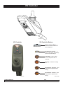
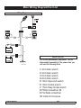
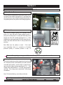
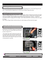
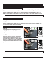
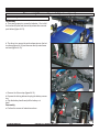
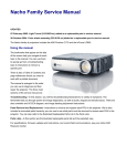
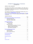
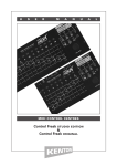
Quickie S-11 Service Manual
©2005 Sunrise Medical Inc.
100740 Rev A
Quickie S-11 Troubleshooting Guide
INTRODUCTION ...................................................... 0.1
Specifications
VSI Controller ........................................................... 0.2
Plugs/Connectors ..................................................... 0.3
Main Wiring Diagram/Tool List ................................. 0.4
Troubleshooting - No Power .......................Section 1
Step
Step
Step
Step
Step
Step
Step
Step
Step
Step
1.0
1.1
1.2
1.3
1.4
1.5
1.6
1.7
1.8
1.9
Circuit Breaker Reset .................................. 1
Test Joystick ................................................ 1
Battery Test .................................................. 1
Recharging the Batteries ............................. 2
Not Charging................................................ 2
Battery Connection Check ........................... 2
Battery Wire Harness.................................... 3
Battery Fuse ................................................ 3
Circuit Breaker Test ..................................... 3
Main Harness............................................... 3
Understanding Controller Display ..............Section 2
2.1
2.2
2.3
2.4
2.5
2.6
2.7
Maximum Speed Indicator Ripples ...................... 4
Maximum Speed Indicator Flashes...................... 4
Battery Gauge is Steady ...................................... 4
Battery Gauge Flashes Slowly ............................. 4
Battery Gauge Steps Up ...................................... 4
Battery Gauge Blinks Every 2.5 Seconds ............ 4
Battery Gauge Flashes Rapily ............................. 4
Understanding VSI Controller Diagnostics Codes
........................................................................Section 3
3.1 1 Bar (1 Red) Low Battery Voltage ..................... 5
3.2 2 Bars (2 Red) - Left Motor Disconnected .......... 5
3.3 3 Bars (3 Red) - Left Motor Wiring Trip .............. 6
3.4 4 Bars (3 Red,1 Yellow)
Right Motor Disconnected ........................................... 7
3.5 5 Bars (3 Red, 2 Yellow)
Right Motor Wiring Trip ............................................... 8
3.6 7 Bars (3 Red, 4 Yellow)
Possible Joystick Trip .................................................. 9
3.7 8 Bars (3 Red, 4 Yellow, 1 Green)
Possible Control System Trip ...................................... 9
3.8 9 Bars (3 Red, 4 Yellow, 2 Green)
Solenoid Brake Trip ..................................................... 9
3.9 10 Bars (3 Red, 4 Yellow, 3 Green)
High Battery Voltage.................................................. 10
Disassembly/Reassembly,
Adjustment/Maintenence .............................Section 4
Step
Step
Step
Step
Step
Step
Step
Step
Step
1
2
3
4
5
6
7
8
9
(Controller and Seat) ..................................... 11
(Seat Posts) ................................................... 12
(Shroud) ......................................................... 13
(Caster Arm) .................................................. 13
(Charger)........................................................ 14
(Battery) ......................................................... 15
(Motor/Wheel) ................................................ 16
(Check/replace Motor Brushes) ..................... 17
(Wire Harnesses) ........................................... 18
INTRODUCTION
Please read and follow instructions in this service manual before attempting to troubleshoot
or repair this product for the first time.If there is anything in this Service Manual that is not
clear, or if you require additional Technical assistance, contact Sunrise Medical at: (800)
333-4000 option 2, then option 1.
Safely troubleshooting and/or repair of this product depends on your diligence in following
the instructions within this manual. Sunrise Medical is not responsible for injuries or damage resulting from a person’s failure to exercise good judgement and/or common sense.
There are warning symbols used in this document to focus attention on any hazard that could effect the safety of the individual troubleshooting the chairs covered in this Service Manual.
This Service Manual has been compiled as a troubleshooting guide for the Quickie S-11.
Photographs and content may differ from the actual products in some cases due to changes
in specifications and other factors.
This Service Manual is intended for use by persons with a basic working knowledge and the
skills required in servicing and maintaining Power Wheelchairs. Persons without a General
Working knowledge and expertise in the servicing of this product should not carry out troubleshooting procedures. This can result in problems with future servicing, and/or damage
to the unit.
Parts and configuration or specifications of Products included in this Service Manual
are subject to change without prior notice.
SUNRISE MEDICAL
QUICKIE S-11 SERVICE MANUAL
2005
PAGE 0.1
VSI Controller
SMASP0X01
VSI Controller Buttons
VSI Controller
Battery Condition Meter- A
series of ten LED’s, which indicate charge level.
Speed/Profile indicator- A
series of five LED’s, whichdisplay
speed and profile settings
On/Off Key- Press to power
on or off the power chair or
Controller.
Horn Key- Activates a warning
horn.
Speed/ Profile Decrease. Used
to decrease the Speed/ Profile
setting.
Speed/ Profile Increase. Used
to Increase the Speed/ Profile
setting.
CNTRLLR BTNS
SMASP0P01
SUNRISE MEDICAL
QUICKIE S-11 SERVICE MANUAL
2005
PAGE 0.2
Plugs/Connectors
1 = 0 Vdc
1
3
2
1 = 24 Vdc
1
2
3
2 = 0 Vdc
2 = Inhibit 3
3 = Inhibit 1/ Programmer
3 = 24 Vdc
Charger port
Outside View
3-pin connect
Outside View
3pin
charger port
9pin
Controller and Harness
+24 Vdc Solenoid Brake Input
Motor Plug
0 Vdc
0 Vdc
24 Vdc
24 Vdc
9
LH Motor +
LH Motor -
1
2
3
4
4-pin connect
1 = Brake Solenoid
RH Motor -
RH Motor +
2 = Brake Solenoid
3 = Motor
4 = Motor
9-pin Connect Harness Socket Face
SUNRISE MEDICAL
QUICKIE S-11 SERVICE MANUAL
2005
PAGE 0.3
Main Wiring Diagram/Tool List
Wiring Diagram
Indicator
Light
AC INPUT
CHARGER
24v BRAKE
SOLENOID
24v BRAKE
SOLENOID
LEFT
MOTOR
RIGHT
MOTOR
BLACK
FUSE
BLACK
RED
RED
Front Battery
ORANGE
BLACK
Basic Tool List
FUSE RED
ORANGE
Rear Battery
Circuit Breaker
WIRE_DGM1
For correct maintenence, adjustment, and for
disassembly/reassembly of the power chair you
will need the following tools:
1. 3mm Allen wrench
2. 4mm Allen wrench
3. 5mm Allen wrench
4. 6mm Allen wrench
5. 13mm Open-end wrench
6. 13mm Socket wrench
7. 17mm Deep Socket wrench
8. Phillips screwdriver #2
9. Flat blade screwdriver
10. Cutter for the zip-tie
SUNRISE MEDICAL
QUICKIE S-11 SERVICE MANUAL
2005
PAGE 0.4
Section 1
Troubleshooting: No Power
1.0 Circuit Breaker Reset
If On/off button is pressed and no light or bar is shown, check
for tripped circuit breaker (see figure A1.0.1) and make sure
all connections are clean and tight (including the batteries). If
the problem persists, then perform the following diagnostics.
A1.0.1
1.1 Test Joystick
Check that the voltage is going to the controller, set the
meter to dc volts and take a voltage reading from pin 1
(using the red lead) and pin 2 (using the black lead) to the
charger port of the VSI controller (see figure A1.1.1) If the
voltage meter reads approximately 24 volts, replace the controller, if the meter reads less than 12 volts, proceed to the
next step.
V DC 200
1000
OFF
750
20
200 V AC
200u
2000m
2000u
200m
20m
20M
200m
2000K
10A
200K
OHM
20K 2000
V
mA COM
200
A DC
10A
DIGITAL MULTIMETER
A1.1.1
Note: Make sure the polarity is correct. If the reading is intermittent, there is a connection or Controller
problem.If polarity is reversed proceed to step 1.6
1
2
3
If the total Battery Voltage reads approx. 24 V, and the Polarity is correct, replace the controller.
1.2 Battery Test
Check that the batteries are fully charged and in good condition. Remove the seat, and the battery cover, with controller
connected and turned on, use the meter to check the voltage across the battery terminals (see figure A1.2.1). If the
voltage meter reads between 12 -13.5 volts, then proceed to
next step. If the voltage meter reads below 12volts,charge
the batteries.
Note: To find a bad battery, use a battery load tester.
A1.2.1
If the voltage meter reads below 12 volts, charge the batteries.
SUNRISE MEDICAL
QUICKIE S-11 SERVICE MANUAL
2005
PAGE 1
1.3 Re-Charging the Batteries
If the total Battery voltage is less than 18 Volts, charge each Battery separately with a 12 Volt Trickle Charger for a few
hours. This should bring the voltage back up to the level that the On-Board Charger will activate.
1.4 Not Charging
Check the charger indicator light in the front shroud. If it is not lighted, check the connection from the light to the charger.
Check the Circuit Breaker Box and make sure it is not tripped. Make sure the 3 pin Charger plug is connected properly
and is in good condition. Check all batteries and harness connections following steps 1.2 and 1.5 - 1.9 Check the
connection from the A/C charging outlet to the charger. If none of these actions have corrected the problem, then replace
the charger.
Note: On Board Charger Indicator Light shows Amber color when charging, and Green when fully charged.
1.5 Battery Connection Check
Check that the female Beau plug on the chair has voltage.
Set the meter to dc volts and measure pins 5 (using the red
lead of the meter) and 7 (using the black lead of the meter)
as shown in (figure A1.5.1).
If the voltage meter reads full voltage, then measure pins
6 (using the red lead of the meter) and 8 (using the black
lead of the meter) as shown in (figure A1.5.2). If both the
measurements read full voltage, then replace the controller,
or else proceed to the next step.
V DC 200
1000
OFF
750
20
200 V AC
200u
2000m
2000u
200m
20m
20M
200m
2000K
10A
200K
A1.5.1
1
3
2
4
5
7
6
8
OHM
20K 2000
V
mA COM
A DC
200
10A
DIGITAL MULTIMETER
9
V DC 200
1000
OFF
750
20
200 V AC
200u
2000m
2000u
200m
20m
20M
200m
2000K
10A
200K
A1.5.2
1
3
2
4
5
7
6
8
OHM
20K 2000
V
mA COM
A DC
200
10A
DIGITAL MULTIMETER
9
If both of the measurements read full voltage, then replace the controller.
SUNRISE MEDICAL
QUICKIE S-11 SERVICE MANUAL
2005
PAGE 2
1.6 Battery Wire Harness
Check that the battery wire harness has the polarity correct.
Set the meter to dc volts and measure the connector with
the red lead on the red wire contact (top of the connector)
and the black lead on the black wire contact (bottom of the
connector) as shown in (figure A1.6.1). If both battery wire
harnesses have full voltage and correct polarity, then proceed to step 1.8. If voltage is absent proceed to step 1.7. If
polarity is reversed correct battery wiring.
V DC 200
1000
OFF
750
20
200 V AC
200u
2000m
2000u
200m
20m
20M
200m
2000K
10A
200K
A1.6.1
OHM
20K 2000
V
mA COM
A DC
200
10A
DIGITAL MULTIMETER
If polarity is reversed correct battery wiring.
1.7 Battery Fuse
Check that the battery fuse is in good condition. With the
batteries disconnected remove the fuse cap, inspect the
fuse to see if the fuse is blown. To make sure the fuse is
not blown, set the meter to ohms and measure the resistance across the fuse. see (figure A1.7.1). If the meter
reads more than one ohm, change the fuse, or else proceed to the next step.
V DC 200
1000
OFF
750
20
200 V AC
200u
2000m
2000u
200m
20m
20M
200m
2000K
10A
200K
A1.7.1
OHM
20K 2000
V
mA COM
A DC
200
10A
DIGITAL MULTIMETER
If the meter reads more than one ohm, change the Battery fuse.
1.8 Circuit Breaker Test
V DC 200
To check the circuit breaker set the meter to ohms and
measure the resistance across the circuit breaker as shown
in (figure A1.8.1). If the meter reads more than 1 ohm,
then change the circuit breaker, otherwise proceed to next
step.
1000
OFF
750
20
200 V AC
200u
2000m
2000u
200m
20m
20M
200m
2000K
10A
200K
OHM
20K 2000
V
mA COM
A DC
200
10A
DIGITAL MULTIMETER
A1.8.1
If the meter reads more than 1 ohm, then change the circuit breaker.
1.9 Main Harness
If the above steps did not correct the problem, change the
main harness.
If the previous steps did not correct the problem, change the main harness.
SUNRISE MEDICAL
QUICKIE S-11 SERVICE MANUAL
2005
PAGE 3
Section 2
Understanding Controller Display
2.1 The Maximum Speed Indicator Ripples
The wheelchair is locked. To unlock the wheelchair, deflect the joystick forwards until the control system
chirps. Then deflect the joystick in reverse until the control system chirps. Release the joystick, there
will be a long beep. The wheelchair is now unlocked.
To lock the wheelchair, while the control system is switched on, depress and hold the on/off button. After
1 second, the control system will chirp. Now release the on/off button, deflect the joystick forwards
until the control system chirps, and deflect the joystick in reverse until the control system chirps. Release
the joystick, there will be a long beep. The wheelchair is now locked.
2.2 The Maximum Speed Indicator Flashes
This indicates that the chair is charging via on-board charger. The chair will be ready to drive as soon as
the charger is unplugged.
2.3 Battery Gauge is Steady
This indicates that all is well.
2.4 Battery Gauge Flashes Slowly
The control system is functioning correctly, but you should charge the battery as soon as possible.
2.5 Battery Gauge Steps Up.
the wheelchair batteries are being charged with the offboard charger. You will not be able to drive the
wheelchair until the charger is disconnected and you have reset the control system by switching off the
power and then powering up again.
2.6 Battery Gauge Blinks Once Every 2.5 Seconds
The control system has "gone to sleep" because the wheelchair has not been driven for a period of time.
The time period depends on the programming of the system. To re-start, reset the system by switching
off the power and then powering up again.
2.7 Battery Gauge Flashes Rapidly (even with the joystick released)
The control system safety circuits have been activated and the control system hasbeen prevented from
moving the wheelchair. This indicates a system trip, i.e. the VSI has detected a problem somewhere in
the wheelchair's electrical system. Please refer to Section 3 (VSI Controller Diagnostics).
SUNRISE MEDICAL
QUICKIE S-11 SERVICE MANUAL
2005
PAGE 4
Section 3
Understanding VSI Controller Diagnostics Codes
3.1 One Bar - Low Battery Voltage
This code could indicate discharged batteries, failed batteries, or poor battery connections. Begin by recharging the batteries and then refer to Section 1 to check batteries and connections.
3.2 Two Bars - Left Motor Disconnected
The left hand motor has a bad connection. Check the connections to the left hand motor.
Test Left Motor Open
Check that the batteries are fully charged and in good
condition; and check all cables and connections. Check
the connections to the left motor, look for a loose or damaged connector. Remove the 9-pin Beau plug and check
the resistance across pin 3 and pin 4 as shown in (figure
A3.2.1). If the meter reads between 0 to 1.5 ohms, then
replace the controller.
V DC 200
1000
OFF
750
20
200 V AC
200u
2000m
2000u
200m
20m
20M
200m
2000K
10A
200K
1
5
3
4
6
20K 2000
V
mA COM
A DC
200
7
9
2
OHM
A3.2.1
8
10A
DIGITAL MULTIMETER
If the meter reads between 0 to 1.5 ohms, then replace the controller.
Otherwise, check both brushes on the left motor. (Refer to
Section 4 Step 9 of this Service Manual for easiest access).
Ensure that the brushes are not excessively worn, (replace
as required). Top access for Motor brush shown in (figure
A3.2.2)(requires shroud removal).
A3.2.2
Use the meter to check the resistance across the two bottom contacts (thicker wires) on the 4-pin motor connector
as shown in (figure A3.2.3). If the meter reads between 0
to 1.5 ohms, then replace the main harness. If none of the
above corrects the problem, replace the left motor.
V DC 200
1000
OFF
750
20
200 V AC
200u
2000m
2000u
200m
20m
20M
200m
2000K
10A
200K
A3.2.3
OHM
20K 2000
V
mA COM
A DC
200
10A
DIGITAL MULTIMETER
If the meter reads between 0 to 1.5 ohms, then replace the main harness.
If none of the above corrects the problem, replace the left motor.
SUNRISE MEDICAL
QUICKIE S-11 SERVICE MANUAL
2005
PAGE 5
Understanding VSI Controller Diagnostics Codes (cont.)
3.3 Three Bars - Left Motor Wiring Trip
The left hand motor has a short circuit to a battery connection.
V DC 200
1000
OFF
750
20
Test Left Motor Short
Check that the batteries are fully charged and in good condition; and check all cables and connections. Check the
connections to the left motor, look for a loose or damaged
connector. Take a resistance reading from pin 3 to pin 9
and pin 3 to pin 7 or pin 8, see (figure A3.3.1) and (A3.3.2),
if the all the circuits are open (resistance is greater than 10
K ohm), then replace the controller. If the reading is short
(resistance is less than 10 K ohm), proceed to check the
4-pin motor connector.
200 V AC
200u
2000m
2000u
200m
20m
20M
200m
2000K
10A
200K
1
6
4
V
mA COM
200
A DC
10A
DIGITAL MULTIMETER
9
2
20K 2000
7
5
3
OHM
A3.3.1
8
V DC 200
1000
OFF
750
20
200 V AC
200u
2000m
2000u
200m
20m
20M
200m
2000K
10A
200K
1
5
3
OHM
20K 2000
V
mA COM
4
6
A DC
7
9
2
200
A3.3.2
8
10A
DIGITAL MULTIMETER
If the all the circuits are open (resistance is greater than 10 K ohm), then replace the controller.
Measure the resistance from the bottom contact of the red
thick wire on the 4-pin left motor connector to each of the
top contacts of the connector see (figure A3.3.3). Measure
the resistance from the bottom contact of the black thick
wire on the 4-pin left motor connector to each of the top
contacts of the connector see (below right). If all of the
readings are open, then replace the main harness. If any
of the readings are short, then replace the left motor.
V DC 200
1000
OFF
750
20
200 V AC
200u
2000m
2000u
200m
20m
20M
200m
2000K
10A
200K
OHM
20K 2000
V
mA COM
200
A DC
10A
DIGITAL MULTIMETER
A3.3.3
Test 1
Test 2
Test 3
Test 4
If all of the readings are open, then replace the main harness.
If any of the readings are short, then replace the left motor.
SUNRISE MEDICAL
QUICKIE S-11 SERVICE MANUAL
2005
PAGE 6
Understanding VSI Controller Diagnostics Codes (cont.)
3.4 Four Bars- Right Motor Disconnected
The right hand motor has a bad connection. Check the connections to the right hand module.
Test Right Motor Open
Check that the batteries are fully charged and in good
condition, and check all cables and connections. Check
the connections to the right motor, look for a loose or damaged connector. Remove the 9-pin Beau plug and check
the resistance across pin 1 and pin 2 as shown on (figure
A3.4.1). If the meter reads between 0 to 1.5 ohms, then
replace the controller.
V DC 200
1000
OFF
750
20
200 V AC
200u
2000m
2000u
200m
20m
20M
200m
2000K
10A
200K
1
5
3
7
4
20K 2000
V
mA COM
200
A DC
10A
DIGITAL MULTIMETER
9
2
OHM
6
A3.4.1
8
If the meter reads between 0 and 1.5 ohms, then replace the controller.
Otherwise, check both brushes on the right motor. (Refer to
Section 4 Step 9 of this Service Manual for easiest access).
Ensure that the brushes are not excessively worn, (replace
as required). Top access for Motor brush shown in (figure
A3.4.2) (requires shroud removal).
A3.4.2
Use the meter to check the resistance across the two
bottom contacts of the thicker wires on the 4-pin motor
connector as shown in (figure A3.4.3). If the meter reads
between 0 to 1.5 ohms, then replace the main harness. If
none of the above corrects the problem, replace the right
motor.
V DC 200
1000
OFF
750
20
200 V AC
200u
2000m
2000u
200m
20m
20M
200m
2000K
10A
200K
A3.4.3
OHM
20K 2000
V
mA COM
200
A DC
10A
DIGITAL MULTIMETER
If the meter reads between 0 and 1.5 ohms, then replace the main harness. If this does not correct the problem, then replace the right motor.
SUNRISE MEDICAL
QUICKIE S-11 SERVICE MANUAL
2005
PAGE 7
Understanding VSI Controller Diagnostics Codes (cont.)
3.5 Five Bars - Right Motor Wiring Trip
The right hand motor has a short circuit to a battery connection.
V DC 200
1000
OFF
750
20
200 V AC
200u
2000m
Test Right Motor Short
Check that the batteries are fully charged and in good condition, and check all cables and connections. Check the
connections to the right motor, look for a loose or damaged
connector. Take a resistance reading from pin 2 to pin 9
see (figure A3.5.1). Take a resistance reading from pin 2
to pin 7 or pin 8 see (figure A3.5.2), if the all the circuits are
open (resistance is greater than 10K ohms), then replace
the controller.
2000u
200m
20m
20M
200m
2000K
10A
200K
1
5
3
OHM
20K 2000
V
mA COM
9
2
6
4
A DC
200
7
A3.5.1
8
10A
DIGITAL MULTIMETER
V DC 200
1000
OFF
750
20
200 V AC
200u
2000m
2000u
200m
20m
20M
200m
2000K
10A
200K
1
5
3
OHM
20K 2000
V
mA COM
9
2
4
6
A DC
200
7
A3.5.2
8
10A
DIGITAL MULTIMETER
If the all the circuits are open (resistance is greater than 10K ohms), then replace the controller.
If the reading is short (resistance is less than 10 K ohms)
on any of the readings, proceed to check the 4-pin motor
connector. Measure the resistance from the bottom contact
of the red thick wire on the 4-pin right motor connector
to each of the top contacts of the connectors see (figure
A3.5.3). Measure the resistance from the bottom contact
of the black thick wire on the 4-pin right motor connector to
each the top contacts of the connector (below right). If all
of the readings are open, then replace the main harness. If
any of the readings are short, then replace the right motor.
V DC 200
1000
OFF
750
20
200 V AC
200u
2000m
2000u
200m
20m
20M
200m
2000K
10A
200K
OHM
20K 2000
V
mA COM
200
A DC
10A
DIGITAL MULTIMETER
A3.5.3
Test 1
Test 2
Test 3
Test 4
If all of the readings are open, then replace the main harness.
If any of the readings are short, then replace the right motor.
SUNRISE MEDICAL
QUICKIE S-11 SERVICE MANUAL
2005
PAGE 8
Understanding VSI Controller Diagnostics Codes (cont.)
3.6
Seven Bars - Possible Joystick Trip
A joystick trip is indicated. Make sure that the joystick is in the center position before switching on the control system.
Check that the batteries are fully charged and in good condition, examine the joystick for damage. This fault can be
caused by a joystick that fails to center itself due to being dirty, bent or broken. If this is the case, replace the controller.
If the joystick fails to center because it is bent or broken, replace the controller
3.7
Eight Bars - Possible Control System Trip
A control system trip is indicated. Make sure that all connections are secure.
Controller Fault
Check that the batteries are fully charged and in good condition, and check all joystick connections and cables. If this
does not correct the problem, then replace the controller.
3.8 Nine Bars - Solenoid Brake Trip
1
Brake Fault
The parking brakes have a bad connection. Check the
parking brake and motor connections. Make sure the control system connections are secure.
5
7
6
8
3
9
2
4
V DC 200
1000
OFF
750
20
2000u
200m
20m
20M
200m
2000K
10A
200K
Brake Fault
Check battery connections and cables. Set the meter to
ohms and measure the resistances from pin 9 to pin 7 of
the 9-pin beau plug see (figure A3.8.1.) Measure the resistance from pin 9 to pin 8 of the 9 pin Beau connector see
(figure A3.8.2).If both readings are approximately 30 ohms,
replace the controller.
200 V AC
200u
2000m
OHM
20K 2000
V
mA COM
A DC
200
10A
DIGITAL MULTIMETER
A3.8.2
1
3
5
7
6
8
9
2
4
V DC 200
1000
OFF
750
20
200 V AC
200u
2000m
2000u
200m
20m
20M
200m
2000K
10A
200K
A3.8.2
OHM
20K 2000
V
mA COM
200
A DC
10A
DIGITAL MULTIMETER
If both readings are approximately 30 ohms then replace the controller
SUNRISE MEDICAL
QUICKIE S-11 SERVICE MANUAL
2005
PAGE 9
Understanding VSI Controller Diagnostics Codes (cont.)
3.8 Nine Bars - Solenoid Brake Trip (cont.)
Test Motor Connections
V DC 200
If either or both readings are incorrect, then measure the
resistance on the two small contacts on the 4-pin motor
connector see (figure A3.8.3). If both motor connectors
read approximately 60 ohms, then replace the main harness. Otherwise, replace the motor that does not read
approximately 60 ohms.
1000
OFF
750
20
200 V AC
200u
2000m
2000u
200m
20m
20M
200m
2000K
10A
200K
A3.8.3
OHM
20K 2000
V
mA COM
200
A DC
10A
DIGITAL MULTIMETER
If both motor connectors read approximately 60 ohms, then replace the main harness. Otherwise, replace
the motor that does not read approximately 60 ohms.
3.9 Ten Bars - High Battery Voltage
An excessive voltage has been applied to the control
system. This is usually caused by a poor battery connection. Check the battery connections.
V DC 200
1000
OFF
750
20
Battery Fault
Check that the batteries are fully charged, the correct voltage and in good condition. Take a voltage reading from
pin 1 and pin 2 of the charger port of the VSI controller, see
(figure A3.9.1) If the meter reads more than 30 volts, then
check the charger. Otherwise, replace your controller.
200 V AC
200u
2000m
2000u
200m
20m
20M
200m
2000K
10A
200K
A3.9.1
OHM
20K 2000
V
mA COM
200
A DC
10A
DIGITAL MULTIMETER
1
2
3
If the meter reads more than 30 volts replace the charger,
If the Batteries, connections, and voltage level are correct replace the controller.
SUNRISE MEDICAL
QUICKIE S-11 SERVICE MANUAL
2005
PAGE 10
Section 4
Disassembly/Reassembly, and Adjustment
Step 1 - Controller and Seat
Note: When using the terms “Right Hand, Left Hand” this is referenced as if seated in the chair.
Disassembly
a. Squeeze down the locking legs of the 3 pin charger plug
and unplug it from the rear of the chair. (figure A4.1).
b. Rock the controller plug back and forth until it is loose
and then unplug it.
Note: Remember to lay cables on the seat otherwise they
may become tangled when taking off the seat.
c. Remove the Front Seat Post Knobs (figure A4.3).
d. Lift up the rear seat post latching levers and push the
seat forward. (figure A4.2).
e. Remove the front seat post knobs and slide the seat
backward and lift it off of the base.
A4.1
Reassembly
a. Line up the front seat frame with the front seat posts,
slide the seat forward to the stops and let the seat frame
rotate down in to the rear seat post latching brackets.
b. Make sure the latching levers are locked flat against the
seat post brackets.
c. Plug the controller plugs into the plug receptacles at the
rear of the chair.
d. Install the Front Seat Post Knobs (figure A4.3).
A4..2
A4.3
SUNRISE MEDICAL
QUICKIE S-11 SERVICE MANUAL
2005
PAGE 11
Disassembly/Reassembly, and Adjustment (cont)
Adjustment
Note: There is a setscrew in each “saddle” of the front
seat post brackets that can adjust the free play of the
seat frame in the bracket. Adjustment of this part is
accomplished by using a 3 mm Hex wrench. After
adjustment, ensure that the latching levers are fully
seated and the locking pin can be installed see
(figure A4.4).
A4.4
Step 2 - Seat Posts
Disassembly
a. Pull the left spring loaded release pin to disengage
post (figure A4.5). While holding the left spring loaded
release pin, remove the seat post.
d. Pull out the three remaining quick release pins, remove
all other seat posts (figure A4.6).
A4.5
Reassembly
a. perform the reverse of instructions above.
A4.6
SUNRISE MEDICAL
QUICKIE S-11 SERVICE MANUAL
2005
PAGE 12
Disassembly/Reassembly, and Adjustment (cont)
Step 3 - Shroud
Disassembly
a. Lift the center shroud from the main frame (figure A4.7).
Note: Center shroud is attached using a hook and loop fastener system.
b. Use 4mm allen wrench to remove the fenders (figure
A4.8).
Reassembly
a. perform the reverse of instructions above.
A4.7
A4.8
Step 4 - Caster Arm
Disassembly
a. Use 6mm allen wrench and 17mm deep socket wrench to
remove the mounting bolt (figure A4.9).
Reassembly
a. perform the reverse of instructions above.
Adjustment
A4.9
Note: The front caster arm can be adjusted from pivoting
slowly (figure A4.10).
a. Use a 4mm Allen wrench to back off the set screw and
use a 8mm bolt head (13mm Allen wrench) to loosen or
tighten the socket head bolt and make the proper adjustment (operator preference).
Set Screw
Socket Head Bolt
A4.10
SUNRISE MEDICAL
QUICKIE S-11 SERVICE MANUAL
2005
PAGE 13
Disassembly/Reassembly, and Adjustment (cont)
Step 5 - Charger
Disassembly
a. Peel the velcro strip apart, and remove the on-board
charger (figure A4.11).
b. Slide the female charger plug out of the beau plug
bracket (figure A4.12)
c. Depress the locking tabs and unplug the A/C plug and
charger light indicator plug.
Reassembly
a. Perform the reverse of instructions above.
A4.11
A4.12
SUNRISE MEDICAL
QUICKIE S-11 SERVICE MANUAL
2005
PAGE 14
Disassembly/Reassembly, and Adjustment (cont)
Step 6 - Battery
Disassembly
a. There are two ways to access the batteries. One is fold
the back and flip the seat forward by release the rear seat
post latches (figure A4.13).
A4.13
b. The other is to remove the quick release pins on the bottom frame (figure A4.14) and removes the top main frame
and seat (figure A4.15).
A4.14
A4.15
c. Remove the Velcro strap (figure A4.16).
d. Depress the locking tabs and unplug the battery connectors.
e. Grip the battery handle and pull the battery out
base.
Reassembly
a. Perform the reverse of instructions above.
A4.16
SUNRISE MEDICAL
QUICKIE S-11 SERVICE MANUAL
2005
PAGE 15
Disassembly/Reassembly, and Adjustment (cont)
Step 7 - Motor/Wheel
Disassembly
Note: For ease of disassembly, set the base frame on a
block where all four wheels are at least 1 inch above the
ground.
a. Unwrap the wire looms from the motor and pull the
motor connector out (figure A4.17).
b. Depress the motor connector locking tab and unplug it.
c. Straighten the lock washer tab of the drive wheel.
d. Use a 13mm socket wrench to remove the drive
wheel retention bolt, then pull the drive wheel out from the
motor shaft (figure A4.18).
e. Use a 5mm Allen wrench to remove the 4 mounting
screws
(figure A4.19).
f. Pull the motor-wheel assembly out .
Note: If the drive wheel is difficult to remove, then remove
the wheel plate screws (5mm Allen head)
A4.17
A4.18
Reassembly
a. Perform the reverse of instructions above.
Note: Torque specifications
* Motor mounting screws 15-20 ft-lbs
* Wheel retention bolt 15-20 ft-lbs
* Wheel plate screw 15-20 ft-lbs
Adjustment
Note: There is a suspension bumper on the frame that limits
the top frame’s movement (figure A4.20).
a. Use a 13mm open wrench to loosen or tighten the jam
nut and make the proper adjustment (operator preference).
A4.19
A4.20
SUNRISE MEDICAL
QUICKIE S-11 SERVICE MANUAL
2005
PAGE 16
Disassembly/Reassembly, and Adjustment (cont)
Step 8 - Check / Replace Motor Brushes
Disassembly
Access to Motor Brushes
a. For quick access to Motor Brushes, perform steps 6b of
this section.
b. Use a flat blade screwdriver to remove the
motor brush cap and then remove the brushes for inspection.
(figure A4.21).
c. Inspect Motor brushes for excessive wear, uneven wear,
and/or severe discoloration.
d. If any of these conditions exist, replace/install both
brushes for the motor in question.
Hint: Make sure that the brushes are seated properly
before re-installing the brush caps.
Reassembly
a. Reassemble your S11, by performing the Reverse of
steps 6b.
SUNRISE MEDICAL
QUICKIE S-11 SERVICE MANUAL
A4.21
2005
PAGE 17
Disassembly/Reassembly, and Adjustment (cont)
Step 9 - Wire Harness
Disassembly
a. Remove all the zip ties on the base frame.
b. Unwrap all the wire loom ties securing the harness to the
frame.
c. For the main harness, remove the two screws that holding
the female beau plug (figure A4.22).
d. Remove the circuit breaker locking nut and push it
through the bracket (figure A4.23), then remove the main
wire harness.
e. For the light and A/C harness, remove the rear shroud
(figure A4.24)
and then remove the mounting screws on the A/C plug
bracket.(figure A4.23).
f. Push the light harness through the bracket.
g. Pull the A/C harness through the bracket.
A4.22
Reassembly
a. Reverse above instructions.
Adjustment
Note: The circuit breaker can be removed without removing
the main harness.
a. Pull the quick disconnect terminal out from the bottom of
the circuit breaker, then remove the circuit breaker locking
nut.
A4.23
A4.24
SUNRISE MEDICAL
QUICKIE S-11 SERVICE MANUAL
2005
PAGE 18