1
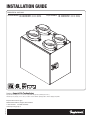
InstallatIon GuIde
RESIDENTIAl uSE oNly
Greentek Models SS 3.80 FSD HRV
SS 3.80 FSD ERV
(Item No. 102208)
(Item No. 102210)
Imperial Models SS 3.80 FSD HRV
SS 3.80 FSD ERV
Product of Imperial Air Technologies
Imperial Air technologies Inc. reserves the rights to modify a product, without prior notice,
whether in price, design, color or codes, in order to offer at all times quality products that are highly competitive.
Item# 102337
Imperial Air Technologies
480 Ferdinand Blvd., Dieppe, NB E1A 6V9
1-888-724-5211 Fax 506 388-4633
www.imperialgroup.ca
(Item No. 102257)
(Item No. 102259)
ImPorTAnT - PleAse reAd mAnuAl before InsTAllATIon
CAuTIon: Do not install in a cooking area or connect directly to any appliance. Turn off all integral disconnects before servicing.
noTICe: Prior to installing, serious consideration must be taken to insure this ventilation system will operate properly if integrated to any other type
of mechanical system, i.e. a forced air system, or an air handling unit. To insure proper operation & compatibilities of both system, it is required that the
airflow’s of the Heat Recovery Ventilator (HRV) or Energy Recovery Ventilator (ERV) be balanced, by following the procedures found in this manual.
lImITATIons: The product is for residential applications only. Must be installed in accordance with all national and local regulations, building and
safety codes.
To reduCe or AvoId The hAzArds of eleCTrIC shoCk And fIre:
CAuTIons ConCernIng The oPerATIon And full effICIenCy of ThIs ProduCT:
• Before servicing or cleaning the HRV system, always remove the
power cord from the AC wall outlet.
• To reduce the hazards of electric shock or fire, do not perform any
service to the HRV system other than those stated in the operating
manual instructions.
• Toreducetheriskofelectricshock,thisventilationsystem(HRV/ERV)
comes equipped with a 3-prong plug-in. This plug will fit in a polarized
outlet only one way.
• Donotuseventilationsystemforoutdoorapplication.
• Do not pull or twist power cord when disconnecting it from the
ventilation system. Grasp the plug firmly, not the cord.
• Donotmodifythepowerpluginanyway;ifmodified,riskofelectric
shock fire or even damage to the unit may occur.
• Do not use the ventilation system for removal of flammable fumes,
gases or connect directly to any appliances.
• UseadedicatedAC120Voutletonly.
• Donotobstructorcovertheairintakeorairoutletoftheventilation
system.
• Donotmodify,repairordisassemblethissystem.Thesetasksareto
be performed by authorized serviced personnel only. Fire, electrical
shock and/or bodily injury may occur if these warnings are not
followed.
• To prevent injuries, do not operate the ventilation system, while
servicing or maintaining. There are impeller wheels turning at a very
high speed that must fully stop rotating prior to accessing the inside of
the unit.
• Alwaysassesstheoperationoftheventilationsystemonhowitmay
interact with vented combustion equipment (ie. Gas Furnace, Oil
Furnace, Combustion, Appliances, etc.)
• Donotuseforswimmingpool/spaapplications.
AbouT us
Imperial Air Technologies Inc. is the only manufacturer that offers you a complete range of products designed to improve indoor air quality, and that
provides a wide selection of accessories to facilitate installation.
Our vision – To offer a complete range of products that satisfies environmental concerns.
Whether your needs involve ventilation or filtration, we have the customized solution for you, with its range of quality products backed by the best
warranty in the industry.
ConTenTs
seCTIon
1. Ventilation requirements . . . . . . . . . . . . . . . .
2. Fitting equivalent lengths . . . . . . . . . . . . . . . .
3. Types of Installations . . . . . . . . . . . . . . . . . .
4. Installation Kit. . . . . . . . . . . . . . . . . . . . . . .
5. Finding a suitable installation area for HRV or ERV .
6. Installation of the HRV / ERV . . . . . . . . . . . . . .
7. Insulated Flex from Unit to Outside Wall . . . . . . .
8. Condensation Drain Line . . . . . . . . . . . . . . . .
9. Dedicated Electric Receptacle . . . . . . . . . . . . .
10. Outside Fresh Air and Exhaust Air Hoods . . . . . .
11. The matrix™ High Performance Ventilation Hood .
12. Benefits of the Duotrol™ System. . . . . . . . . . .
13. Balancing the unit . . . . . . . . . . . . . . . . . . . .
14. Controls Connection . . . . . . . . . . . . . . . . . .
15. Wiring Diagrams for furnace interlock systems . .
16. Troubleshooting . . . . . . . . . . . . . . . . . . . . .
17. Maintenance . . . . . . . . . . . . . . . . . . . . . . .
Page 2
.
.
.
.
.
.
.
.
.
.
.
.
.
.
.
.
.
.
.
.
.
.
.
.
.
.
.
.
.
.
.
.
.
.
.
.
.
.
.
.
.
.
.
.
.
.
.
.
.
.
.
.
.
.
.
.
.
.
.
.
.
.
.
.
.
.
.
.
.
.
.
.
.
.
.
.
.
.
.
.
.
.
.
.
.
.
.
.
.
.
.
.
.
.
.
.
.
.
.
.
.
.
.
.
.
.
.
.
.
.
.
.
.
.
.
.
.
.
.
PAge
. . 3
. . 4
. . 5
. . 7
. . 7
. . 7
. . 8
. . 8
. . 8
. . 9
. . 9
. . 10
. . 10
. . 12
. . 13
. . 14
. . 15
1. venTIlATIon requIremenTs
deTermIne your
venTIlATIon needs
InsTAllATIon
A. room Count Calculation
lIvIng sPACe
Master Bedroom
number of rooms
Cfm (l/s)
Cfm requIred
————
x 20 cfm (10 L/s)
=
————
How much fresh air do I need?
Good air quality is based in part
on the capacity of the home’s
ventilation system.
With Basement
————
x 20 cfm (10 L/s)
=
————
Single Bedroom
————
x 10 cfm (5 L/s)
=
————
Living Room
————
x 10 cfm (5 L/s)
=
————
Usually, the HRV’s/ERV’s capacity
is measured in CFM (Cubic Feet per
Minutes) or L/s (Liters per Seconds)
of fresh air being distributed in the
living space. The Room Count
Calculation or the Air Change per
Hour Method shows you how to
determine your ventilation needs.
(see chart on right)
Dinning Room
————
x 10 cfm (5 L/s)
=
————
Family Room
————
x 10 cfm (5 L/s)
=
————
Recreation Room
————
x 10 cfm (5 L/s)
=
————
Other
————
x 10 cfm (5 L/s)
=
————
Kitchen
————
x 10 cfm (5 L/s)
=
————
Bathroom
————
x 10 cfm (5 L/s)
=
————
Laundry Room
————
x 10 cfm (5 L/s)
=
————
Utility Room
————
x 10 cfm (5 L/s)
=
————
ToTAl ventilation requirement (add last column)
=
————
1 CFM = 0.47189 L/s
1 L/s = 3.6 m3/hr
b. Air Change per hour method
TOTAL cu ft X 0.35 per hr = total
Take total and divide by 60 to get CFM
example: A 25’x 40’ house with basement
1,000 Sq. ft. x 8’ high x 2(1st floor + basement) = 16,000 cu. ft.
16,000 cu. ft. x 0.35 ACH = 5,600 cu. ft.
5,600 cu. ft. / 60 Minutes = 93.3 CFM
93.3 Cfm Is your venTIlATIon need
Page 3
2. fITTIng equIvAlenT lengThs
- Flex pipe equivalent length is
smooth pipe x2
- Flex fitting equivalent length is
smooth fitting x2
- 90º perimeter pipe elbow
equivalent length = 10 ft. (3.0 m)
noTe: Where flex duct is used
to make 90º elbow
equivalent length = 20 ft. (6.1 m)
noTe: Where flex duct is used
to make 45º elbow
equivalent length =
10 ft. (3.0 m)
- Round wall cap spring
damper or screen
equivalent lengths =
60 ft. (18.29 m)
- Y-equal sides
equivalent length = 10 ft. (3.0 m)
- Y-Side branch
equivalent length =
35 ft. (10.7 m)
- Angle boot
equivalent length = 30 ft. (9.14 m)
- Tee take-off
equivalent length =
50 ft. (15.24 m)
- Wall grill 50% free area
equivalent length = 15 ft. (4.6 m)
- Increaser/Reducer
equivalent length
= 8 ft. (2.43 m)
- Round plastic diffuser
equivalent length = 100 ft. (30.5 m)
noTe: Maximum airflow assumes
diffuser is in full open position.
Page 4
- 45º perimeter pipe elbow
equivalent length = 5 ft. (1.52 m)
3. TyPes of InsTAllATIons
IndePendenT sysTem
InsTAllATIon
figure 3.1
This application uses a devoted
duct system for the supply
and the exhausting of stale air
accumulated in the home.
It is recommended to install fresh
air grilles in all bedrooms and living
areas. Exhaust the stale air from
the bathroom, kitchen and laundry
room. (see figure 3.1)
ImPorTAnT: For optimal performance
of your HRV or ERV, the installation of an
optional 6” round galvanized backdraft
damper is required on the fresh air to
home duct work.
exhAusT AT The
sourCe And suPPly In
The reTurn
This application uses a devoted
duct system for the exhausting of
stale air accumulated in the home.
The fresh air is dumped into the
return air duct and is distributed
thru the home by the existing
supply air ductwork of the forced
air system. (see figure 3.2)
Make sure when using this application
that your fresh air duct connection to
the forced air system return air duct
is not less than 10ft (3 m) upstream of
the return plenum connection to the
forced air system. Check with your
local code or the forced air system’s
manufacturer. The HRV and forced air
system must be in continuous mode,
to achieve maximum comfort and to
avoid cross-contamination.
noTe To InsTAller: Dwellings
with multiple forced air systems
requires one HRV/ERV per system.
figure 3.2
From Bathroom
or Kitchen
To living space
A
6'
(1.83 m)
b
18" (457 mm)
HRV / ERV
Forced Air System
A+b=noT less ThAn 10fT (3 m)*
ImPorTAnT: The duct bringing outdoor air to the return air
plenum must be equipped with a manual dumper to balance
the outdoor airflow.
* For minimum distance between return and forced
air system, check with your local building codes and
forced air system manufacturer.
Insure the unit runs in conjunction
with forced air system (Ref. wiring
diagram for furnace interlock)
ImPorTAnT: For optimal performance of your HRV or ERV, the installation of an optional 6" round galvanized backdraft damper is required on the fresh air to home duct
work. When performing duct connections, always use approved tools and material. Also use steel duct connections for these type of installs.
Page 5
3. TyPes of InsTAllATIons (COnTInUED)
exhAusT And suPPly
In The reTurn
figure 3.3
A
When using this application make
sure that there is minimum 3 feet
(0.9 m)between the fresh air and
exhaust air connections of the
HRV/ERV in the return air duct.
(see figure 3.3)
Make sure when using this application
that your fresh air duct connection to
the forced air system return air duct
is not less than 10ft (3 m) upstream of
the return plenum connection to the
forced air system. Check with your
local code or the forced air system’s
manufacturer. The HRV and forced air
system must be in continuous mode,
to achieve maximum comfort and to
avoid cross-contamination.
noTe To InsTAller: Dwellings
with multiple forced air systems
requires one HRV/ERV per system.
Insure the unit runs in conjunction
with forced air system (Ref. wiring
diagram for furnace interlock)
6'
(1.83 m)
To living space
b
18" (457 mm)
3ft (0.9 m)
mInImum
dIsTAnCe
HRV / ERV
Forced
Air System
A+b=noT less ThAn 10fT (3 m)*
* For minimum distance between return and forced
air system, check with your local building codes and
forced air system manufacturer.
ImPorTAnT: The duct bringing outdoor air to the return air
plenum must be equipped with a manual dumper to balance
the outdoor airflow.
Simplified Connection
ImPorTAnT: Building and combustion appliance
installation codes do not allow return air grilles or
openings such as "breather tee" or indirect connections
in an enclosed room that is susceptible to spillage of
combustion appliances.
Indirect Connection
Breather Tee
2"
(51 cm)
ImPorTAnT: For optimal performance of your HRV or ERV, the installation of an optional 6" round galvanized backdraft damper is required on the fresh air to home duct
work. When performing duct connections, always use approved tools and material. Also use steel duct connections for these type of installs.
Page 6
4. InsTAllATIon kIT
InCluded In The
InsTAllATIon kIT:
figure 4.1
•4Collars
•4Caps,PressureTaps(9753K74)
•1CondensationDrainLine
•1DrainAdapterwithNut
•12screws(#10x11/4”)
•2screws(#8x3/8”)
•AC120Vpowercord
•WallMountingBracket
5. fIndIng A suITAble InsTAllATIon AreA for hrv or erv
The HRV/ERV unit should be installed in a mechanical room or as close to an outside wall as possible. This
would assure a short run of insulated flexible duct.
The HRV/ERV unit must always be installed in an area where the air is tempered to avoid freezing of the
condensate line. The contractor should install the unit in an area that is very accessible to allow the homeowner
easy access for maintenance.
It is very important to install an electric receptacle (115v) near the HRV / ERV, a separate circuit breaker is
also recommended. You should have access to a condensate drain near the HRV/ERV to avoid the use of
condensate pump.
6. InsTAllATIon of The hrv / erv
ImPorTAnT Minimum installation
requirements
A) Minimum two 2"x 4" (50.8 mm
x 101.6 mm) wood wall studs
and minimum 3⁄8 " (9.5 mm) thick
drywall is required to secure
the HRV/ERV wall bracket.
b) Support for weight of 80 lbs,
which includes HRV/ERV, duct
connections and accessories.
Proper installation requires that
the unit be secure to the wall. If
there is no wall studs available,
please secure a 3 ⁄4" plywood
to wall studs then fasten wall
mounting bracket to plywood.
figure 6.1 Installation of the wall bracket. Secure with two #10 x 11⁄4" screws.
TIP To InsTAller: If the unit is not
level, improper drainage will occur
and could lead to moisture and
leakage problems.
It is recommended to use
approximately 16 inches of flexible
duct between the HRV/ERV and
your rigid duct. The flex duct is
mounted the same way to the HRV/
ERV as the insulated flex.
figure 6.2 Hang HRV/ERV to wall mounting
bracket.
figure 6.3 When completing the procedure
make sure that the HRV/ERV is leveled.
figure 6.4 Proceed to secure HRV/ERV to
bracket with the two #8 x 3⁄8 " screws.
Page 7
7. InsulATed flex from unIT To ouTsIde WAll
TIP To InsTAller: To ensure a
better installation and to avoid an
undesired bend in the duct, align
the duct with the collar before
securing over the four hooks.
WArnIng: Always fix and secure
the 5" collars with the screws supplied.
Avoiding this critical step the unit will
figure 7.1 Insert vinyl duct over the hooks
accumulate condensation.
and seal with a Tie wrap.
figure 7.2 Insert insulation inside the collar.
figure 7.3 Finish by taping the duct on the
collar.
Once insulated flex is attached to the collar, slide collar in keeper section, fixed collar to the unit with four
screws supplied in installation kit.
figure 7.4 Slide collar on the unit.
Figure 7.5 Fix and secure the collars to the HRV/
ERV with the #10 x 11⁄4" screws, supplied in kit.
8. CondensATIon drAIn lIne
Insert the threaded drain adapter
thru the bottom of the HRV/ERV and
hand tighten the plastic nut, and with
a wrench tighten the nut another half
turn to assure a better seal.
Install the condensate line
(included in drain kit). Insert
condensate tubing by pushing
clear plastic line over drain
adapter. Make condensate trap
by looping the clear plastic tubing.
This procedure is to avoid foul odor
to enter the HRV or ERV.
figure 8.1 Make a loop in condensate line, not be subject to
freezing temperatures.
9. dedICATed eleCTrIC reCePTACle
ImPorTAnT: Always consult
a certified technician to insure
proper installation of main power.
noTe: If LED light on the Duotrol
remains green, motors not
energized controls do not operate.
Polarization in main AC outlet are
inverted.
It is recommended that the HRV/
ERV have a dedicated receptacle
with 115v. It is not recommended to
connect unit with an extension cord.
Page 8
figure 9.1 Insert the power cord on top of the unit. Press firmly to
make sure the power cord is secure.
figure 8.2 Use a condensate pump if you don’t have access to a drain.
10. ouTsIde fresh AIr And exhAusT AIr hoods
TIP To InsTAller: We recommend
and it is good practice to have a
minimum of 6ft (1.83 m) between
the supply and exhaust vents,
unless using a concentric vent
design to prevent contamination of
intake air.
6ft (1.83 m)
noTe: Outdoor air intake hoods shall
be located to avoid contamination
from sources such as:
•Exhaustairopenings
•Driveways(autoexhaust)
18" (457 mm)
•Combustionappliances
•Gasmeters,oilfillpipes
•Garbagecontainers
•Atticsorcrawlspaces
•Under deck or other areas of
questionable air quality
figure 10.1 Locating Outside Hoods
ImPorTAnT: Always consult your national and
local regulations, building and safety codes.
11. The mATrIx™ HIGH PERFORMAnCE VEnTILATIOn HOOD
AIrfloW &
InsTAllATIon
Exterior wall
Exhaust air from home
“TOP”
ImPorTAnT: Install ventilation hood
a minimum of 18” (457mm) above grade.
Do not install under a deck, enclose
porch, patio, garages, crawl spaces or
attics.
Fresh air to home
“BOTTOM”
WArnIng: Insure the ventilation
hood is at a minimum clearance of 6 ft
(1.83 m) away from the exhaust vents of
a combustion source and contaminants.
Exhaust air
to outside
Ex: Gas furnace, dryer, gas boilers,
range hoods, barbecue, garbage bin,
driveway or garage.
Ventilation
cap
Uniquely design individual
insulated transition duct (UL 94 Rated)
Transition
connector plate
ImPorTAnT: Always consult national and your
local regulations, building and safety codes.
lImITATIon: This product is for residential
applications only.
Fresh air from outside
Airflow Performance Data
Supply Air Flow Performance
0.25
External Static Pressure
in wg (Pa = n x 248.36)
lImITATIons: This product is for
residential applications only. Must be
installed in accordance with all current
national and local regulation building
and safety codes.
Exhaust Air Flow Performance
0.25
External Static Pressure
in wg (Pa = n x 248.36)
AIrfloW
PerformAnCe dATA
0.2
0.15
0.1
0.05
0
30
45
60
75
90
CFM (L/s = n x 0.4719)
105
120
0.2
0.15
0.1
0.05
0
30
45
60
75
90
105
120
CFM (L/s = n x 0.4719)
Limitations: This product is for residential applications only. Must be installed in accordance with all current national and local regulation building and safetyPage
codes.
9
12. benefITs of The duoTrol™ sysTem
mode seleCTor
ACTs As A mode seleCTor
•Intermittent
InTermITTenT: When the selector switch is in the intermittent position
the HRV/ERV will only run when there is a call for ventilation by any
control. At that time the unit will run on high speed until the condition
is satisfied.
•Continuous
•Off
ConTInuous: When the selector switch is in the continuous position
the HRV/ERV will run continuously on pre set speed except when there
is a call for override by any control.
off: When the selector switch is in the off position the HRV/ERV will not
come on even if there’s a call for ventilation by any control.
sPeed AdjusTmenT
+ buTTon: Increase the speed of the selected motor.
•IncreaseSpeed(+)
– buTTon: Decrease the speed of the selected motor.
•DecreaseSpeed( – )
13. bAlAnCIng The unIT
WITh The duoTrol™
sysTem
GREEn LIGHT
MODE SELECTOR
usIng The seleCTor sWITCh
TIP To InsTAller: When on Balancing Mode, the
Selector Switch allows you to choose the motor you
want to set.
A) Closed duoTrol Cover
b) oPen duoTrol Cover
1. InTer (Exhaust Motor)
1. uP (Exhaust Motor)
2. ConT (Both Motors)
2. mIddle (Both Motors)
3. off (Supply Motor)
3. doWn (Supply Motor)
duoTrolTm bAlAnCIng sysTem
YELLOW LIGHT
BALAnCInG MODE ProCedures, sTePs 1 Through 8.
Page 10
step 1: Press the (+) and (–) buttons simultaneously
until you see the yellow light. Once the indicator light
turns yellow you are in balancing mode.
step 5: Then perform the same operation on the stale
air side by selecting the «InTER» position on the
DuotrolTM.
step 2: When in balancing mode the selector switch
becomes the motor selector switch. InTER (Right
Motor), COnT (Both Motors) and OFF (Left Motor)
step 6: The «COnT» position will allow you to
adjust the cfm on both motors proportionately (if
necessary).
step 3: Once the total cfm needed is determined,
you can start balancing the HRV/ERV. Set your fresh
air supply by selecting the «OFF» position on the
Duotrol TM. Install your magnehelic gauge and air flow
grid in the fresh air duct.
step 7: Once this is completed, you have set the high
speed on your HRV/ERV. To lock balancing mode you
must press (+) and (–) buttons simultaneously and
release. The indicator light will turn green to indicate
normal operation mode.
step 4: Press the (–) button to decrease the cfm or
press the (+) button to increase the cfm.
step 8: Once high speed is set and locked, switch
to continuous on the Duotrol TM. By using (+) and (-)
buttons set low speed on the HRV/ERV.
13 bAlAnCIng The unIT (COnTInUED)
WITh The duoTrol
sysTem And
The InTegrATed
bAlAnCIng TAPs And
mAgnehelIC gAuge.
HIGH (Exhaust Air to Outside)
LOW (Exhaust Air from Home)
Magnehelic gauge
Balancing Tap Connection*
Magnehelic gauge
HIGH (Fresh Air to home)
LOW (Fresh Air from Outside)
Connecting the Magnehelic gauge to the collar balacing taps, then proceed to section 13 (on page 10) Duotrol TM
Balancing System Procedures and follow the Steps 1 through Step 8.
bAlAnCIng ChArT
The balancing chart is based on a
Delta P (DP) measurement (also
located on the access panel of the
ventilation system)
noTe: To perform a proper install,
the External Static Pressure (ESP)
needs to be measured at each
of the 4 stations. Then proceed
to measure the Delta P(DP) to
determine the corresponding
airflow (e.g. 50 CFM), then do the
iteration until the unit is balanced
both the (ESP and airflows).
Balancing Chart when using collar pressure taps.
Pressure
Pa
50
62
75
87
100
112
125
137
150
162
175
187
199
Fresh Air
in. wg
0.20
0.25
0.30
0.35
0.40
0.45
0.50
0.55
0.60
0.65
0.70
0.75
0.80
L/s
44
41
39
37
35
33
30
29
26
24
22
19
17
Exhaust Air
CFM
93
87
83
79
74
69
65
61
56
50
46
41
36
L/s
43
40
37
36
36
34
32
28
24
22
19
17
15
CFM
90
85
79
77
76
71
67
60
51
47
41
36
31
*ImPorTAnT: Once balancing is complete, insure all four pressure taps are sealed with the rubber caps. Pressure taps
(9753K74) supplied in the installation kit.
WITh An AIrfloW grId
& mAgnehelIC gAuge
Magnehelic Gauge with Air Flow Grid
Inserting Air flow grid in duct
Seal Air flow grid in duct with duct tape.
Page 11
14. ConTrols ConneCTIon
rd-1 (2 wires)
G
G
R
R
rd-2, rd-3P, rd-4P (4 wires)
R
R
G
G
B
B
W
W
B
B G
G R
R
Jumper
Jumper
JP-4*
JP-4*
LVC
LVC Version
Version 1
1
2
2 Relays
Relays
R
RW
W B
B G
G
To
To Casing
Casing
Screw
Screw
for Ground
Ground
for
Jumper
Jumper
JP-4*
JP-4*
LVC
LVC Version
Version 2
2
CAuTIon: Minimum wire requirements is LVT18 CSA/UL 4 strain to insure proper connection.
Page 12
1
1 Relay
Relay
15. WIrIng dIAgrAms for furnACe InTerloCk sysTems
sTAndArd forCed AIr
InTerloCkIng WIrIng
A relay is normally used when tying
a ventilation system to the forced air
distribution system. Our Duotrol System
is equipped with an internal relay that
will activate the forced air system’
ventilator when there is a demand from
the HRV /ERV. The Duotrol System will
activate the InTERLOCK relay during
the following modes: Continuous,
Override,Recirculation and Defrost.
See wiring diagram.
Low Voltage HRV Controller
Force Air System
legend: -------- Field Installed Low Voltage
Figure 15.1 Standard forced air wiring diagram
AlTernATe forCed AIr
InTerloCkIng WIrIng
Some forced air system thermostat
will activate the cooling system when
tied using the «Standard forced air
interlocking wiring».
If you have identify this type of
thermostat you must proceed with the
«Alternate Forced Air Wiring».
loCATIng The
WIrIng dIAgrAm
noTe To InsTAller: Wiring
Diagram for the entire line of HRV/ERV
Models are placed on the back of each
Exhaust motor bracket.
CAuTIon: Thermostat that control
A/C system must use the Alternate
Interlock Wiring Diagram.
Force Air System
Low Voltage HRV Controller
*Before tying the HRV/ERV to
a forced air system, always
refer to system’s manual or
manufacturer.
Thermostat
legend: -------- Field Installed Low Voltage
Figure 15.2 Alternate forced air wiring diagram
WArnIng: Always disconnect the unit prior to making any connections. Failure to disconnecting the power could result in electrical shock or can
damage the electronic boards, wall controls and/or unit.
CAuTIon: Minimum wire requirements is LVT18 CSA/UL 4 strain to insure proper connection.
Page 13
16. TroubleshooTIng
quesTIon / ITem
dIAgnosIs / soluTIon
•HRV/ERVnotrunning
• Verifybreakerinmainelectricalpanel
• VerifytheHRVorERVisintheONposition
• VerifytheallwallcontrolsswitchontheHRVorERVareactivatedtosupplypowertotheunit
• UnplugHRVorERVverifyifthecontrolleriswiredcorrectlytotheconnectionboxonthesideoftheunit
• Verifymainoutletpolarization
•Airistoodry
• Reducethehumiditylevelonthecontroller
• Reducecontinuousairflowrate
• Switchventilationmodefromcontinuoustointermittent
• Humidifierrecommendedifheatingsourceisaforcedairsystem
•Airtoohumid
• SuggestcontinuousoperationofHRVorERV
• Increasehumiditylevelondehumidistat
• Increasecontinuousairflowrate
• Insufficientventilation,checkcapacity
• Internalsourceofmoisture,e.g.heatingwoodstoreinbasement,possibleleaksorpoorinsulationR-valueandor
dryer is venting in basement
•Vibrationornoise
• Verifythatvibrationmountingstraps,hangingchainsorwallbracketisusedforhangingtheunits.
• VerifythatflexibleductconnectionsareusebetweentheHRVorERVandtherigidduct.
• Verifythatthemotorsareoperatingandarenotobscuredbyanydebris
• Insuremotormovesfreelywithturningbyhand.
•Coldair
• Misplacedsupplyoutlets
• Defrostnooperatingcorrectly
• TheHRVorERVnotproperlybalanced
• Highairflowonfurnacecontinuousmode
• InsureHRVorERVisinterlockwhenintegratedwithforcedairsystem
•ContaminationorPollutants
• Insureproperclearanceofventilationhoodsfromsourceofcontaminants
Refer to section 10. Outside Fresh Air and Exhaust Air Hoods.
•Condensation
• VerifythattheHRVorERVisleveltoinsureproperdrainage
• VerifythattheductconnectionarefixandsecuredwithscrewstotheHRVorERV.
• Verifythecoldsideductconnectionsarefullyinsulatedandthatvaporbarrieristapedtoinsureaproperseal.
• Lookforsignsofcrushedsection,failingductstraps,puncturevaporbarrier,missinginsulation.
• Insurepropersealofvaporbarriertooutsidewall.
• Lookforsignofwateraccumulation/leakage/dripping
• Verifythatthedrainconnectionisnotkinked;the“P”trapisnottoclosetounitorobscuredwithdebris.
Page 14
17. mAInTenAnCe
rouTIne mAInTenAnCe
seven-sTeP mAInTenAnCe
sChedule
With routine preventative maintenance,
you can avoid unnecessary problems,
ensure the effectiveness of your HRV,
and prolong its life. For additional
specific instructions, refer to your HRV
operating manual or ask the contractor
who installed or services the HRV to
demonstrate the proper maintenance
procedures.
WArnIng:
BE SURE TO DISCOnnECT THE
ELECTRICAL POWER BEFORE
SERVICInG YOUR SYSTEM
1. Clean or replace air filters. Filters,
which are located within the HRV
should be cleaned every two to three
months. Filters should be vacuumed
first, then washed with a mild soap
and water. Most washable filters will
last several years before needing to
be replaced.
2. Clean the exterior intake and
exhaust vents of obstructions.Check
the outside vents regularly to ensure
that the screen openings are not
obstructed by grass, bushes, leaves,
snow or other debris.
3. Clean and inspect the heat-exchange
core and aluminum louvers (Ref. Fig.
17.1 for proper orientation of louvers).
Twice a year and clean it as required
(consult your owner’s manual
for instructions on inspecting and
cleaning the core). A build-up of dust
and dirt can restrict airflow and reduce
the efficiency of your HRV/ERV. After
inspection and cleaning, make sure the
core is replaced right-side-up.
4. Clean the condensate drain and pan.
Twice a year, check the condensate
drain and tubing to ensure that
they are open and free-flowing.
The tubing can be disconnected for
cleaning. The condensate drain must
havea“trap”inthetubingthattraps
a quantity of water – to prevent air
from entering the HRV/ERV via this
tubing
5. Service the fans. The fans on the
HRV/ERV’s are designed to operate
continuously without lubrication.
Inspect the blower fans periodically
for dirt on the blades, and remove
it by gently brushing the blades or
using a vacuum cleaner.
6. Clean the grilles and inspect the
ductwork. Clean the grilles when
they are dusty. At least once a year,
visually inspect the ductwork leading
to and from the HRV. Damaged ducts
can lead to condensation problems,
including wet insulation, water on
the floor and, ice build-up. If the
insulation itself is damaged.
7. Arrange for an annual servicing.
Your HRV/ERV should undergo
annual general servicing by a
certified contractor and who is
familiar with your HRV. If possible,
have your furnace and HRV serviced
atthesametime;thiswillresultin
less inconvenience and cost than
two separate visits.
All Imperial Air Technologies products are backed by the best limited warranty on the market.
Imperial Air technologies Inc. reserves the rights to modify a product, without prior notice, whether in price, design, color or codes, in order to offer at all times quality
products that are highly competitive.
AlWAys ConsulT your nATIonAl And loCAl regulATIons buIldIng And sAfeTy Codes.
Page 15
Item# 102337
Imperial Air Technologies
480 Ferdinand Blvd., Dieppe, NB E1A 6V9
1-888-724-5211 Fax 506 388-4633
www.imperialgroup.ca
Item# 102337
Imperial Air Technologies
480 Ferdinand Blvd., Dieppe, NB E1A 6V9
1-888-724-5211 Fax 506 388-4633
www.imperialgroup.ca
17. ENTRETIEN
HORAIRE D'ENTRETIEN
Avec un entretien préventif régulier,
vous pouvez éviter les problèmes
inutiles, assurer l'efficacité de votre
VRC/VRE et prolonger sa durée de
vie. Pour obtenir des instructions
supplémentaires, consultez le manuel
d'installation de votre système ou
demandez à l'entrepreneur qu’il vous
démontre les procédures d'entretien.
AVERTISSEMENT:
TOUJOURSDEBRANCHERTOUT
APPAREIL ELECTRIQUE AVANT
L’ENTRETIEN.
1. Nettoyez ou remplacez les filtres.
Les filtres, qui sont situés dans le
VRC/VRE doivent être nettoyés.
Nettoyer les filtres régulièrement
soit tous les deux à trois mois
ou selon le besoin à l'aide d'un
aspirateur en premier et rincé a l’eau
tiède. Remplacer selon le besoin.
2. Vérifiez les évents muraux à
l'extérieur régulièrement pour
s'assurer que les ouvertures sont
pas obstruées par l'herbe, feuilles,
neige ou autres déchets quel
compte.
3. Nettoyer le noyau d'échange.
Inspecter le noyau d'échange et les
plaques de distribution d’air (Fig 17.1)
deux fois par ans. Nettoyer selon
le besoin (consultez votre manuel
d’installation et les instructions
qui sont identifiés sur le noyau
d’échange suivre les étapes de
nettoyage) Une accumulation de
poussière et la saleté peut réduire
la circulation de l'air et réduire
l'efficacité de votre VRC/VRE. Après
l'inspection et le nettoyage, assurezvous que le noyau est remplacé
selon les instructions.
4. Nettoyer le drain de condensation
et le bac. Deux fois ans, vérifiez
le drain de condensation pour
s'assurer qu'il n’est pas obstrué
et que la condensation écoule
librement. Le conduit du drain peut
être débranché pour le nettoyage.
Le drain de condensation doit avoir
un « siphon » pour empêcher les
odeurs de pénétrer dans le
VRC/VRE.
5. Les ventilateurs sont lubrifiés à
vie et nécessitent aucun entretien.
Inspecter les lames du ventilateur
périodiquement à l'aide d'un
aspirateur ou une brosse supprimer
la saleté doucement.
6. Nettoyer les grilles et inspectez
les conduits. Nettoyer les grilles
lorsqu'ils sont poussiéreuse. Au
moins une fois par an, inspecter
visuellement les conduits menant
vers et à partir du VRC/VRE. Des
conduits endommagés peuvent
entraîner des problèmes de
condensation ou des fuites d’eau.
7. Un entretien annuel de votre
VRC/VRE et autres systèmes de
CVAC par un technicien certifié
est suggéré.
Produit de Imperial Air Technologies
Imperial Air Technologies Inc se réserve le droit de modifier un produit, sans pré-avis, soit en prix,
conception, couleur ou code pour offrir en tout temps des produits compétitifs de qualité supérieure.
CONSULTEZ TOUJOURS AUPRÈS DES CODES NATIONAUX, LOCAUX ET LES CODES DE SÉCURITÉ.
Page 15
16. DÉPANNAGE
• Assurerquelaconnexiondudrainn'estpasdéforméeetquelesiphonn’estpasobstruédedéchetsquelcompte.
• Assurerlesconnectionsaumurextérieursontentièrementisoléesetquelacoupevapeurestbienenvelopper
et sceller afin d'assurer une bonne étanchéité.
• Vérifiezlesconduitsducôtéfroiddel’appareiletassurerqu’ilssontentièrementisolésetquelacoupevapeur
est bien envelopper et sceller afin d'assurer une bonne étanchéité.
• Vérifierquelesconnexionsdesconduitssontsécuriséesàl’aidedevisauVRC/VRE.
• VérifiezqueleVRC/VREestniveau.
•Condensationoufuitesd‘eau
• Référenceàsection10.Installationdeséventsextérieurs.
• Assurerquelesbonnespratiquessontrespectéesselonlesnormesducodedebâtimentlocaux,
national et de sécurité en ce qui concerne les sources de contamination.
•Contaminationoupolluants
• Sondededégivragedéfectueux.
• Connexionsàunsystèmeairpulsé,assurerqueleVRC/VREestintégréenconjonctionausystèmeàairpulsé.
• Lebalancementdesdébitsd’airnon-conformeduVRC/VRE.
• Vérifierl’emplacementdesgrillesdedistributiond’airfrais.
•Airfroid
• Assurerquelesmoteurssedéplacentlibremententournantàlamain.
• Vérifierquelesmoteursfonctionnentetnesontpasobscurésdedéchetquelcompte.
• Assurerquelesconnexionsdeconduitflexiblesourceantivribrationsontutilisésentrele
VRC ou ERV et le conduit rigide.
• Vérifiezletypedesuspensiondemontagequiestutilisépoursuspendrel’appareil.
•Vibrationsoubruit
• Sourceinterned'humidité,parexempleboisdechauffageentreposerausous-sol,
les fuites possibles ou sécheuse qui évacue au sous-sol.
• Aérationinsuffisante,vérifierlacapacitédel’appareil.
• Augmenterlavitessedudébitd'air.
• Augmenterleniveaud'humiditésurlecontrôleprincipale.
• SélectionnerlemodeventilationcontinuduVRC/VRE.
•Airesttrophumide
• Humidificateurrecommandélorsquelasourcedechauffageestunsystèmeàairpulsé.
• Changerlemodedeventilationàintermittent.
• Réduireledébitd'aircontinu.
• Réduireleniveaud'humiditésurledéshumidistat.
•Airesttropsec
• Vérifierlapolarisationdelasortieprincipale.
• DébrancherleVRCouVRE,vérifiersilescontrôlessontbranchéscorrectementauxconnexions.
• AssurerquelecontrôlemuralspricincipaletleVRCouVREsontactivésafindefournirducourant.
• VérifierleVRCouVREestdanslapositionON.
• Vérifierledisjoncteurdanslepanneauélectrique.
VRCouERVn'exécutenepas
DIAGNOSTIC / SOLUTION
QUESTION / POINT
Page 14
15. DIAGRAMME DE RACCORDEMENT AVEC SYSTÈME À AIR FORCÉ
RACCORD STANDARD AVEC UN
SYSTÈME À AIR FORCÉ
Un relais est normalement utilisé pour
raccorder un système de ventilation
à un système à air forcé. Notre
système DuotrolMD est doté d’un relais
intégral qui permet de commander le
démarrage du ventilateur du système
à air forcé lors d’une demande
provenant du VRC/VRE. Le système
DuotrolMD du VRC/VRE active le
relais INTERLOCK pendant les modes
d’opérations suivants : continu,
demande, recirculation et dégivrage.
Voir diagramme de branchement cicontre.
Contrôle à voltage bas de VRC/VRE
Systèmeàairforcé
Légende : -------- Ligne installée à voltage bas
Figure 15.1 Raccord standard avec un système à air forcé
RACCORD AUXILIAIRE AVEC UN
SYSTÈME À AIR FORCÉ
Certains thermostats du système à air
forcé branché avec le raccord standard
ci-dessus vont activer le système de
climatisation. Lorsque vous identifiez
ce type de thermostat, veuiller procéder
avec l’installation à raccord auxiliaire
avec un système à air forcé.
LOCALISER L’EMPLACEMENT DU
DIAGRAMME DE BRANCHEMENT
NOTE À L’INSTALLATEUR : Le
diagramme de branchement pour tous
les modèles Professionnel, De Luxe ,
séries SS3,12 et SS3,80 sont localisés
à l’intérieur du bras de support sur le
moteur d’évacuation.
Contrôle à voltage bas de VRC/VRE
*Toujours ce référer aux
spécifications du manufacturier
avant de raccorder un VRC/VRE
à un système à air forcé..
Systèmeàairforcé
Thermostat
Legend: -------- Ligne installée à voltage bas
Figure 15.2 Raccord auxiliaire avec un système à air forcé
AVERTISSEMENT: Avantd'effectuertousraccordements,toujoursdébrancherl'appareil,sansdébrancherpourraitcréerlesrisquesdechoc
électrique, endommager les plaques électronique, les contôles mural ou l'appareil.
Page 13
14. CONTRÔLES ET BRANCHEMENT
RD-1 (2 fils)
L’installation d’un contrôle murale
série RD et accessible aux utilisateurs
sur le produit améliore le confort et
pourrait considérablement réduire la
consommation d’énergie du produit
G
G
G
R
R
R
RD-2, RD-3P, RD-4P (4 fils)
R
R
G
G
B
B
W
W
R
G
B
W
MINUTERIE T3 (3 fils)
B
B G
G R
R
B G R
Jumper
JP-4*
Jumper
Jumper
LVC Version
Version 1
1
LVC
JP-4*
JP-4*
LVC Version 1
2 Relays
Relays
2
2 Relays
R
RW
W B
B G
G
RW B G
To Casing
Casing
To
Screw
Screw
To Casing for
for Ground
Ground
Screw
for Ground
Jumper
JP-4*
Jumper
Jumper
JP-4*
LVC
JP-4*
LVC Version
Version 2
2
LVC Version 2
AVIS:UnfilminimumdeLVT18CSA/ULà4brinsestrequipourleraccordement.
Page 12
1 Relay
Relay
1
13 BALANCEMENT DE L’APPAREIL (SUITE)
LE SYSTÈME DE
BALANCEMENT
DUOTROL AVEC PRISES
DE PRESSION INTÉGRER
DE COLLETS
HIGH (Évacuation d'air vicié)
LOW (Aspiration d'air vicié)
Cadran Magnehelic
Prise de pression*
Cadran Magnehelic
HIGH (Distribution d'air frais)
LOW (Aspiration d'air frais)
En reliant le cadran Magnehelic aux prises de pression des collets, procédez alors à la section 13 utilisation du
Duotrol en mode de balancement (page 10) Duotrol et suivent les étapes 1 à l'étape 8.
TABLEAU DE VALEURS
Le tableau de valeurs d’équilibrage
est basé sur une measure de Delta
P (DP) aussi situé sur la panneau
d’accès du VRC/VRE.
NOTE:
Pour
exécuter
un
balancement approprié, la pression
statique externe, doit être mesuré
à chacun des 4 stations. Procèdez
alors pour mesurer le Delta P (DP)
pour determinez la correspondence
des debits d’air, (example 50 PCM)
faitealorsl’itérationjusqu’àceque
le VRC/VRE soit équilibré.(Pression
StatiqueExterneetDébitd’Air)
Tableau de valeurs pour l’équilibrage du VRC/VRE
Pression
Pa
50
62
75
87
100
112
125
137
150
162
175
187
199
Air frais
po d'eau
0.20
0.25
0.30
0.35
0.40
0.45
0.50
0.55
0.60
0.65
0.70
0.75
0.80
L/s
44
41
39
37
35
33
30
29
26
24
22
19
17
PCM
93
87
83
79
74
69
65
61
56
50
46
41
36
Air vicié
L/s
43
40
37
36
36
34
32
28
24
22
19
17
15
PCM
90
85
79
77
76
71
67
60
51
47
41
36
31
*IMPORTANT : Une fois que l'équilibrage est completé, sceller l'extrémité des prises de pressions à l'aide des capuchons
en caouchouc (No. 9753K74), fournis dans la trousse d'installation.
AVEC CADRAN
MAGNEHELIC ET
GRILLE DE LECTURE
DE DÉBIT D’AIR.
Cadran magnehelic avec grille de lecture
de débit d’air.
Insérer la grille dans le conduit.
Sceller la grille avec du ruban adhésif à
conduits.
Page 11
12. BÉNÉFICES DU SYSTÈME DE BALANCEMENT DUOTROL™
INTERMITTENT : Le VRC/VRE s’activera seulement lorsqu’il y aura une
demande de ventilation.
•Intermittent
AGIT DE SÉLECTEUR DE MODE
SELECTEUR DE MODES
•Continu
•Arrêt
CONTINU : Le VRC/VRE fonctionne continuellement en basse vitesse,
excepté lorsqu’il y a une demande de ventilation ou l’unité changera à
haute vitesse.
ARRÊT : La fonction «off» empêche le VRC/VRE de s’activer lors d’une
demande de ventilation.
CONTÔLE DE
BALANCEMENT
+ SÉLECTEUR : Augmente la vitesse.
– SÉLECTEUR : Diminue la vitesse.
•Augmentationdevitesse(+)
•Diminutiondevitesse( – )
13. BALANCEMENT DE L’APPAREIL
WITH THE DUOTROL™
SYSTEM
LUMIÈRE VERTE
SÉLECTEURDEMODE
UTILISATION DU DUOTROL EN MODE
DE BALANCEMENT
CONSEILS IMPERIAL À L’INSTALLATEUR: Le bouton
glissoir vous permet de sélectionner le moteur désiré.
Étape 5 : Ensuite, en sélectionnant le moteur de
droite, répéter les mêmes étapes pour votre débit
d’air vicié.
Étape 1 : Appuyer simultanément sur les boutons +
et – pendant 5 secondes. Une fois que l’indicateur
lumineux devient jaune, vous êtes en mode de
balancement.
3. BAS (moteur d’alimentation)
3. OFF (moteur d’alimentation)
2. MILIEU (les deux moteurs simultanément)
2. CONT (les deux moteurs simultanément)
1. HAUT (moteur d’évacuation)
1. INTER (moteur d’évacuation)
B) PORTE OUVERTE
A) PORTE FERMÉE
PROCÈDURES MODE DE
LUMIÈRE JAUNE
MODE DE BALANCEMENT BALANCEMENT ÉTAPES 1 À 8.
Étape 2 : En mode de balancement, l’interrupteur
de sélection devient le sélecteur de moteur (droit,
ensemble ou gauche)
Étape 3 : Vous pouvez débuter le balancement
des moteurs une fois que les débits de PCM sont
déterminés. Sélectionner le débit d’air frais à l’aide
du sélecteur de moteur gauche sur le système
DuotrolMD.
Étape 6 : En appuyant simultanément sur les boutons,
vous sécuriser le débit. Vous ne pouvez changer le
débit qu’en recommençant les étapes 1 et 2.
Étape 7 : Les étapes 1 à 6 vous permettent de régler le
mode haute vitesse de votre VRC/VRE.
Étape 8 : Maintenant, vous pouvez ajuster le mode
basse vitesse en appuyant sur les boutons (+) et (-).
Étape 4 : En appuyant sur le bouton (-) vous allez
diminuer le montant de PCM et en appuyant sur le
bouton (+), vous allez augmenter le montant de PCM.
Page 10
10. INSTALLATION DES ÉVENT EXTÉRIEURS
CONSEILS À L’INSTALLATEUR :
Nous recommandons un minimum
de 6 pi (1.83 m) entre les évents
d’air frais et de l’air vicié. À moins
d’utilisé un évent concentrique
conçu
pour
empêcher
la
contamination d'air .
6 pi (1.83 m)
NOTE: Les évents extérieurs d'air
frais doivent êtres localisés pour
éviter la contamination à partir des
sources comme :
•Ouverturesd’airvicié
18 po (457 mm)
•Entrée,Garage
(Échappement de véhicule)
•Échappementd’appareilsde
combustion
•Compteursàgaz,pipesdepétrole
•Contenantd'ordures
•Greniersousous-sol
•Sousuneplate-formeoud'autres
secteurs où la qualité de l'air est en
question.
figure 10.1 Localiser l’emplacement des évents sur la maison.
IMPORTANT : Veuillez vérifier auprès des codes
de construction national et locaux.
11. THE MATRIX™ ÉVENT DE VENTILATION HAUTE PERFORMANCE
CIRCULATION D’AIR ET
INSTALLATION
Mur extérieur
Évacuation de l’air vicié
vers l’extérieur.
IMPORTANT: Installez évent de
ventilation à un minimum de 18 po
(457mm) du sol.
Air frais distribué
vers l’intérieur
Ne pas l’installer sous une terrasse,
ni dans un porche fermé, un
garage, grenier ou toutes espaces
non-conditionnés.
AVERTISSEMENT : S’assurez que
l’évent de ventilation matrix tm est à une
distance minimale de 6 pi (1,83 m) des
conduits d’évacuation de toute source
de combustion ou de contaminants : Ex
: Fournaise au gaz, sécheuse, chauffaux
au gaz, barbecue, compteur de gaz,
hôtte de cuisine, poubelle, allée ou
garage.
Air vicié
évacué à
l’extérieur
Conduit simple de transition isolé.
(R4.0 / classé UL 94)
Plaque
de transition
Capuchon de
ventilation
IMPORTANT : Veuillez vérifier auprès des codes
de construction national et locaux.
Air frais provenant de l’extérieur
Rendement de ventilation
RENDEMENT DE
VENTILATION
LIMITATIONS: Ce produit est conçu
pour des applications résidentielles
seulement. Il doit être installé
confomément de tout code national et
local du bâtiment en vigueur.
Évacuation
Alimentation
0.25
Pression statique externe
wg (Pa = n x 248.36)
0.25
Pression statique externe
wg (Pa = n x 248.36)
0.2
0.15
0.1
0.05
0
30
45
60
75
90
105
0.2
0.15
0.1
0.05
0
120
30
45
60
75
90
105
120
PCM (L/s = n x 0.4719)
PCM (L/s = n x 0.4719)
LIMITATIONS : Ce produit est conçu pour des applications résidentielles seulement. Il doit être installé confomément de tout code national et local du bâtiment en vigueur.
Page 9
7. CONDUIT FLEXIBLE ISOLÉS
CONSEILS À L’INSTALLATEUR:
Pour assurer une installation
optimale et pour ne pas nuire à la
trajectoireduconduitflexible,nous
vous recommandons d’aligner le
conduit à l’unité avant de l’installer
par-dessus les quatres agraffes de
fixation.
AVERTISSEMENT: Toujours utiliser figure 7.1 Insérer le conduit en vinyl pardessus les quatres agraffes de fixation.
les écrous fournient dans la trousse
d’installation afin de fixer le système
de collet. Ceci pour assurer un
fonctionnement optimal du système de
ventilation et éliminer les chances de
condensation du cabinet du système de
ventilation.
figure 7.4 Glisser le collet à l’appareil.
figure 7.2 Insérer la gaine isolante à
l’intérieur de la double paroie du collet
amovible.
figure 7.3 Terminer par sceller le coupe
vapeur au collet avec du ruban.
Figure 7.5 Attacher les collets avec l’aide
d’écrous (#10 x 1 1⁄4 po de longueur).
8. DRAIN ET CONDUIT DE CONDENSATION
Une longueur de tuyau de drain de
10 pi est fournie avec l’unité. Installer
tout d’abord l’adapteur de drain dans
le trou au fond de l’appareil puis fixer
enutilisantl’écrou.Serrerl’adapteur
de drain à la main, ensuite avec une
clé anglaise faite un demi tour pour
assurer l’étenchité.
Installer du tuyau de drain. Former
un siphon avec le conduit pour éviter
que les odeurs ne remontent dans
le système. (Mauvaises odeurs peu
probables à l’intérieur du cabinet car
l’appareil fonctionnera en pression figure 8.1 Former un siphon dans le conduit.
positive.)
figure 8.2 Ensuite, raccorder au renvoi ou à la pompe de condensation
si vous n’avez pas accès au drain du plancher.
9. ALIMENTATION ÉLECTRIQUE
IMPORTANT: Toujours consulter
un technicien certifié pour assurer
une installation adéquate d'une
prise électrique.
NOTE: La lumière LED du Duotrol
est verte et aucun des moteurs ou
contrôle ne s'active. Ceci est que
la polarization de la sortie 120V/AC
est inversé.
figure 9.1 Insérez le cordon électrique fermement dans l’orifice sur
le dessus de l’unité.
Page 8
4. TROUSSE D’INSTALATIONS
TROUSSE D’INSTALLATION
INCLU DANS LA TROUSSE
D’INSTALLATION:
figure 4.1
•4collets
•4 Capuchons pour prise de pression
•2conduitflexibleenvinyl
•1conduitdedrain
•1adapteurdedrainavecnoix
•12écrous(#10x1-1/4po)
•2écrous(#8x3/8po)
•Cordond’alimentation120VAC
•1supportmural
5. CHOISIR L’EMPLACEMENT DE L’UNITÉ VRC
En tous temps, l’unité de ventilation doit être installée dans un endroit chauffé pour éviter le gel de l’unité et du
drain de condensation. On installe habituellement l’unité dans une salle mécanique le plus près possible d’un
mur extérieur où sont installés les évents extérieurs
d’alimentation et d’évacuation, afin de minimiser les longueurs de tuyaux flexibles isolés utilisés pour aller vers
l’extérieur. Il faut prendre en considération il est requi d’avoir une prise consacré de 120 V/AC pour brancher
l’appareil sans avoir besoin une rallonge électrique.Un accès à un drain est requi pour évacuer la condensation
produit par l’unité si on ne veut pas avoir à utiliser une pompe à condensation. Lorsque vous choisirez un
emplacement pour l’unité, pensez qu’il faudra avoir un accès facile pour faciliter l’entretien.
6. INSTALLATION DU VRC / VRE
IMPORTANT Installation minimum
requis.
A) Un Minimum de deux goujons
de 2po ; X 4po ; (50.8 mm X 101.6
mm) est requi pour fixer le
support mural.
B) Un minimum soutien de 80
Lbs. (36.3 Kg), ceci inclut le
VRC/VRE, les conduits de
raccordement et accessoires.
L'installation appropriée exige que
le VRC/VRE soit fixé solidement au
mur.S’iln'yaaucun2x4(50.8mm
x 101.6mm) de disponible, veuillez figure6.1Installationdusupportmural.Sécuriseravecdeuxécrousde#10x1-1/4po.
fixer un morceau de contre-plaqué
minimum3 ⁄4"d’épaisauxgoujons,
ensuite fixer le support mural du
VRC/VRE.
IMPORTANT:Sil’unitén’estpasau
niveau, ceci pourrait augmenter les
chances de causer des problèmes
tel ques des fuites d’eau.
figure 6.2 Fixer l’appareil au support mural.
figure 6.3 La prochaine étape assurezvous que le VRC/VRE est au niveau.
figure 6.4 Terminer l’installation en vous
assurant de sécuriser l’appareil au support
mural.
Page 7
3. TYPE D’INSTALLATIONS (SUITE)
ÉVACUATION ET
DISTRIBUTION DANS
LE RETOUR
figure 3.3
A
Lorsque vous utilisez cette méthode,
assurez-vous qu’il a une distance
minimale de 3 pied (0.9 m) entre les
deux connexions (l’air frais et l’air
vicié) provenant du VRC/VRE dans
le retour d’air du système à air forcé.
(Réf. figure 3.3)
6 pi
(1.83 m)
vers les pièces
habités
B
18 po (457 mm)
Lorsque vous utilisez cette méthode,
assurez-vous qu’il y aie pas moins de
10 pied (3 m) entre la connection du
retour d’air frais provenant du VRC/
VRE et du système à air forcé. Assurer
que le fonctionnement du ventilateur
du système central soit synchronisé
avec le système de ventilation (VRC/
VRE).
NOTE: Les habitations dotté de
plusieurs systèmes à air forcé, nous
recommandons un VRC/VRE par
système. Pour que le ventilateur du
système à air forcé fonctionne au
moment d’une demande de ventilation,
vous devez raccorder votre système
à air forcé à votre VRC/VRE. (Voir
diagramme de branchement)
3 pi (0,9 m)
DISTANCE
MINIMUM
VRC / VRE
Système
à air forcé
A+B=PAS MOINS DE 10pi (3 m)*
* Pour obtenir la distance minimale entre le conduit
dans le retour et le système à air forcé. Veuillez vérifier
auprès des codes de construction locaux et votre
manufacturier de système à air forcé.
IMPORTANT: Le conduit de distribution d'air frais dans
le retour d'air du système à air forcé, doit être équipé d'un
clapet manuel pour équilibrer le débit d'air provenant de
l'extérieur.
Connexion simplifiée
IMPORTANT: Veuillez véfifier auprès des codes
de construction national et locaux en ce qui
concernes les appareils de combustion.Les codes
d'installation ne permettent pas les grilles d'aération
ou des raccordements indirects, dans une salle qui est
susceptible à des fuites de combustion.
Connexion indirecte
"T" d'aspiration
2"
(51 cm)
IMPORTANT: Pour une performance optimale de votre VRC/VRE, l'installation d'un clapet anti-retour galvanisé de 6 po. est exigé sur le conduit d'air frais provenant
del'extérieur.Lorsderaccordementauxconduits,toujoursutiliserdesoutilsetmatériauxapprouvées.Ainsiutiliserdesconduitsetraccordsenacierpourcestypes
d'installation.
Page 6
3. TYPE D’INSTALLATIONS
SYSTÈME INDÉPENDANT
INSTALLATION
figure 3.1
Cette application utilise un
système de conduits uniquement
conçu pour la distribution d’air
frais et pour l’évacuation d’air vicié
accumulé dans la maison.
Il est recommandé d’installer les
grilles de distribution d’air frais
dans toutes chambres à coucher
et pièces utilisées sauf s’il y a
une grille d’évacuation.Les grilles
d’aspiration d’air vicié devraient
être installées dans les salles de
bain, cuisine et salle de lavage.
(telle qu’illustré fig 3.1)
IMPORTANT : Pour une performance
optimale de votre VRC ou VRE,
l'installation d'un clapet anti-retour
galvanisé de 6 po. est exigé sur
le conduit d'air frais provenant de
l'extérieur.
ÉVACUATION À LA SOURCE
ET DISTRIBUTION DANS LE
RETOUR
figure 3.2
Provenant de la salle
de bain ou cuisine
Cette application utilise un système
de conduits uniquement conçu pour
l’aspiration d’air vicié accumulé dans
la maison. (Réf. figure 3.2)
vers les pièces
habités
A
6 pi
(1.83 m)
L’air frais est dirigé dans le retour du
système d’air forcé et est distribué
dans la maison avec l’aide du système
de conduits existant.
B
18 po (457 mm)
Lorsque vous utilisez cette méthode,
assurez-vous qu’il y aie pas moins de
10 pied (3 m) entre la connection du
retour d’air frais provenant du VRC/
VRE et du système à air forcé. Assurer
que le fonctionnement du ventilateur du
système central soit synchronisé avec
le système de ventilation (VRC/VRE).
VRC / VRE
Systèmeàairforcé
A+B=PAS MOINS DE 10pi (3 m)*
NOTE: Les habitations dotté de
plusieurs systèmes à air forcé, nous
recommandons un VRC/VRE par
système. Pour que le ventilateur du
système à air forcé fonctionne au
moment d’une demande de ventilation,
vous devez raccorder votre système
à air forcé à votre VRC/VRE. (Voir
diagramme de branchement)
IMPORTANT: Le conduit de distribution d'air frais dans
le retour d'air du système à air forcé, doit être équipé d'un
clapet manuel pour équilibrer le débit d'air provenant de
l'extérieur.
* Pour obtenir la distance minimale entre le conduit
dans le retour et le système à air forcé. Veuillez vérifier
auprès des codes de construction locaux et votre
manufacturier de système à air forcé.
IMPORTANT: Pour une performance optimale de votre VRC/VRE, l'installation d'un clapet anti-retour galvanisé de 6 po. est exigé sur le conduit d'air frais provenant
del'extérieur.Lorsderaccordementauxconduits,toujoursutiliserdesoutilsetmatériauxapprouvées.Ainsiutiliserdesconduitsetraccordsenacierpourcestypes
d'installation.
Page 5
2. TABLEAU LONGUEUR ÉQUIVALENTE DE DIVERS RACCORD DE TUYAUX
- Conduit flexibles longueur
équivalente de 2x (fois) le
conduit rigide
- Coude plissé 90º longueur
équivalente = 10 pi (3,0 m)
NOTE: Lorsque le conduit
flexible est utilisé comme
raccord de 90º longueur
équivalente = 20 pi (6,1 m)
- Coude plissé 45º longueur
équivalente = 5 pi (1,52 m)
NOTE: Lorsque le conduit
flexible est utilisé comme
raccord de 45º longueur
équivalente = 10 pi (3,0 m)
- Évent mural avec clapet
ou mèche longueur
équivalente = 60 pi (18,29 m)
- Augmenteur/Réducteur
longueur équivalente
= 8 pi (2,43 m)
- Grille mural
longueur équivalente = 15 pi (4,6 m)
- Conduit en "T" longueur
équivalente = 50 pi (15,24 m)
- Sortiedesous-solsansgrille
longueur équivalente =
30 pi (9,14 m)
- Conduit en "Y" 45º longueur
équivalente = 35 pi (10,7 m)
- Conduit en "Y" longueur
équivalente = 10 pi (3,0 m)
- Diffuseur rond en plastique
longueur équivalente =
100 pi (30,5 m)
NOTE: La distribution maximum
du débit d'air est atteint lorsque
le diffuseur est en position
ouvert.
Page 4
1. BESOIN EN VENTILATION
DÉTERMINER
SES BESOINS EN
VENTILATION
Combien d’air frais ai-je besoin?
Une bonne qualité d’air intérieur
est en partie due à la capacité
du système de ventilation de la
maison.
Habituellemement, l’unité de
mesure utilisée pour évaluer un
VRC/VRE est le nombre de PCM
(pieds cubique par minute) ou le
l/s (litres par seconde) d’air frais
distribué dans les pieces d’une
maison.
Nous vous suggérons deux
methods de calcul (présentées cicontre) pour évaluer vos besoins:
La méthode du calcul du nombre
de pièces et la méthode de
changement d’air par heure.
A. Calcul du nombre de pièces
ESPACE
chambre des maîtres
NOMBRE DE PIECES
PCM (L/S)
x 10 PCM (5 L/s)
————
salle de rangement
x 10 PCM (5 L/s)
————
salle de lavage
x 10 PCM (5 L/s)
————
salle de bain
x 10 PCM (5 L/s)
————
cuisine
x 10 PCM (5 L/s)
————
autres
x 10 PCM (5 L/s)
————
salle de recreation
x 10 PCM (5 L/s)
————
pièce familliale
x 10 PCM (5 L/s)
————
salle à dinner
x 10 PCM (5 L/s)
————
salon
x 10 PCM (5 L/s)
————
chambre à coucher
x 20 PCM (10 L/s)
————
avec sous-sol
x 20 PCM (10 L/s)
————
=
=
=
=
=
=
=
=
=
=
=
=
Ventilation totale nécessaire (additionner les colonnes) =
PCM NÉCESSAIRE
————
————
————
————
————
————
————
————
————
————
————
————
————
1 PCM = 0.47189 L/s
1 L/s = 3.6 m 3 /hr
B. Changement d’air par heure
TOTAL pieds cubique X 0.35 par heure = total
Prendre le total et le diviser par 60 pour obtenir le PCM.
Example: Prenons une maison avec un sous-sol de 25 pi x 40 pi
1 000 pi carré x 8 pi de hauteur x 2 (1 rez-de-chaussé + sous-sol) = 16 000 pi cubes
16 000 pi cubes x 0.35 ACH = 5,600 pi. cubes
5,600 pi. cubes / 60 minutes = 93.3 PCM
93.3 PCM EST NÉCESSAIRE
Page 3
IMPORTANT - LIRE LE MANUEL AVANT L’INSTALLATION
ATTENTION : Ne pas installer près d’un appareil de cuisson ni raccorder directement à un appareil.Mettre hors tension tous les sectionneurs
integers avant d’entreprendre le d’épannage.
A NOTER : Avant l’installation, s’assurer que le système de ventilation soit fonctionel s’il est intégré avec un système à air pulsé (Ex: Thermopompe,
Founaise) afin d’assurer le fonctionnement et la compabilité des deux systèmes. Il est requi de balancé les débits d’air du système de ventilation soit
le VRC ou VRE.
ATTENTION : Ce produit est pour application résidentielle seulement. L’installation doit être conforme aux normes nationaux, locaux de construction
et de sécurité.
AVERTISSEMENT: POUR REDUIRE ET ÉVITER LES RISQUES DE CHOC ÉLECTRIQUE ET D’INCENDIE,
D’ÉLECTROCUTION ET DE SÉCURITÉ.
• Ne pas utiliser pour des applications de ventilation humides. (Ex:
piscines ou des bains tourbillons.)
• Ne pas utiliser le système de ventilation (VRC/VRE) pour une
application externe.
• Nepasmodifier,répareroudémonterlesystèmesdeventilation(VRC/
VRE).Ces tâches doivent être faites par un technicien certifié.
• Pourvotreprotection,cetappareilestmunid’uncordond’alimentation
à trois brin.Il s’adapte à une sortie électrique polarisé seulement.
• Ne pas obstruer les sorties ou les entrées d’air du système de
ventilation (VRC/VRE).
• Ne pas modifier ou faire l’entretien à l’appareil de ventilation (VRC/
VRE) seulement à ceux mentionner dans ce manuel d’instruction.
• Seulementutiliserunesortieconsacréeà120VAC.
• Toujourdébranchertoutappareilélectriqueavantl’entretien.
• Ne pas tirer ou tortiller le cordon d’alimentation, pour débrancher
prendre la prise fermement et non le cordon.
• Ne pas utiliser votre système de ventilation (VRC/VRE) pour
l’évacuation de vapeur et de gaz inflammables, explosives ou brancher
directement à aucun appareil ménager.
A PROPOS DE NOUS
Imperial Air Technologies Inc. est le seul fabricant pouvant vous offrir une gamme complète de produits conçus pour améliorer la qualité d'air
intérieur et une multitude d'accessoires pour en faciliter l'installation.
Notre vision - Offrir une gamme complète de produits qui correspondent à la vision environnementale et qui sont en harmonie avec elle.
Que vos besoins soient en matière de ventilation ou de filtration, nous possedont la solution sur mesure pour vous grâce à notre gamme de produits
de qualité appuyée par la meilleure garantie limitée de l'industrie.
TABLE DES MATIÈRES
1. Besoin en ventilation . . . . . . . . . . . . . . . . . . . . . . . . . . . . . . . . . . . . . . . . .3
2. Tableau longueur équivalente de divers raccord de tuyaux . . . . . .4
3. Types d’installations . . . . . . . . . . . . . . . . . . . . . . . . . . . . . . . . . . . . . . . . .5
4. Trousse d’installation . . . . . . . . . . . . . . . . . . . . . . . . . . . . . . . . . . . . . . . .7
5. Choisir l’emplacement du VRC/VRE . . . . . . . . . . . . . . . . . . . . . . . . . . . .7
6. Installation du VRC/VRE . . . . . . . . . . . . . . . . . . . . . . . . . . . . . . . . . . . . . .7
7. Conduits flexibles isolés . . . . . . . . . . . . . . . . . . . . . . . . . . . . . . . . . . . . . .8
8. Drain et conduit de condensation . . . . . . . . . . . . . . . . . . . . . . . . . . . . .8
9. Alimentation électrique . . . . . . . . . . . . . . . . . . . . . . . . . . . . . . . . . . . . . .8
10. Installation des évents extérieurs . . . . . . . . . . . . . . . . . . . . . . . . . . . .9
11. Matrix évent de ventilation . . . . . . . . . . . . . . . . . . . . . . . . . . . . . . . . . .9
12. Bénéfices du système DuotrolMD . . . . . . . . . . . . . . . . . . . . . . . . . . .10
13. Balancement de l’appareil . . . . . . . . . . . . . . . . . . . . . . . . . . . . . . . . . .10
14. Contrôles et branchement . . . . . . . . . . . . . . . . . . . . . . . . . . . . . . . . . .12
15.Diagramme de branchement . . . . . . . . . . . . . . . . . . . . . . . . . . . . . . . 13
16. Dépannage . . . . . . . . . . . . . . . . . . . . . . . . . . . . . . . . . . . . . . . . . . . . . . . 14
17. Entretien . . . . . . . . . . . . . . . . . . . . . . . . . . . . . . . . . . . . . . . . . . . . . . . . . .15
Page 2
MANUEL D’INSTALLATION
UTILISATION RÉSIDENTIELLE SEULEMENT
Greentek - Modèle
SS 3.80 VRC FSD
SS 3.80 VRE FSD
(No. pièce 102209)
(No. pièce 102210)
Imperial - Modèle
SS 3.80 VRC FSD
SS 3.80 VRE FSD
(No. pièce 102257)
(No. pièce 102259)
Produit de Imperial Air Technologies
Imperial Air technologies Inc se réserve le droit de modifier un produit, sans pré-avis, soit en prix,
conception, couleur ou code pour offrir en tout temps des produits compétitifs de qualité supérieure.
Imperial Air Technologies
480 Ferdinand Blvd., Dieppe, NB E1A 6V9
1-888-724-5211 Fax 506 388-4633
www.imperialgroup.ca
Item# 102337