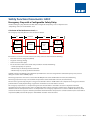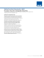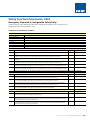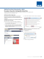
1
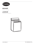
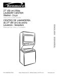
NHP SAFETY REFERENCE GUIDE
440C
SAFETY FUNCTION
DOCUMENTS
Emergency Stop with
a Configurable Safety
Relay
Application Technique
Safety Function Documents: 440C
Safety Function:Emergency
Emergency
a Configurable
Safety
StopStop
with awith
Configurable
Safety Relay
Relay
Products: Emergency Stop, Guardmaster 440C-CR30 Configurable Safety Relay,
100S-C Safety Contactors
Safety Rating: CAT. 4, PLe to ISO 13849-1: 2008
Products: Emergency Stop, Guardmaster 440C-CR30 Configurable Safety Relay, 100S-C Safety Contactors
Safety Rating: CAT. 4, PLe to ISO 13849-1: 2008
Topic
Page
Important User Information
2
General Safety Information
3
Introduction
3
Safety Function Realization: Risk Assessment
Emergency Stop Safety Function
Safety Function Requirements
Functional Safety Description
Bill of Material
Setup and Wiring
Table of Contents:
Introduction
Verification and Validation Plan
Verification of the Configuration
Additional Resources
4
4
4
Important User Information 4
Safety Function Realization
Configuration
Calculation of the Performance Level
3
5
6-3
6-3
6-4
8
General Safety Information
Setup and Wiring
Configuration
18
20
22
24
6-5
6-7
6-10
Calculation of the Performance Level
6-18
Verification and Validation Plan
6-20
Additional Resources
6-23
NHP Safety Reference Guide > Safety Function Documents: 440C
6A-2
Safety Function Documents: 440C
Emergency Stop with a Configurable Safety Relay
Products: Emergency Stop, Guardmaster 440C-CR30 Configurable Safety Relay, 100S-C Safety Contactors
Safety Rating: CAT. 4, PLe to ISO 13849-1: 2008
Introduction
Important User Information
This safety function application example explains how to wire
and configure a Guardmaster® 440C-CR30 configurable safety
relay to monitor a dual channel emergency stop (E-stop) device.
If the E-stop is actuated, or a fault is detected in the monitoring
circuit, the 440C-CR30 relay de-energizes the final control
device, in this case, a redundant pair of 100S-C contactors.
Read this document and the documents listed in the additional
resources section about installation, configuration, and
operation of this equipment before you install, configure,
operate, or maintain this product. Users are required to
familiarize themselves with installation and wiring instructions
in addition to requirements of all applicable codes, laws,
and standards.
Activities including installation, adjustments, putting into
service, use, assembly, disassembly, and maintenance are
required to be carried out by suitably trained personnel in
accordance with applicable code of practice.
If this equipment is used in a manner not specified by the
manufacturer, the protection provided by the equipment may
be impaired.
In no event will Rockwell Automation, Inc. be responsible or
liable for indirect or consequential damages resulting from the
use or application of this equipment.
The examples and diagrams in this manual are included solely
for illustrative purposes. Because of the many variables and
requirements associated with any particular installation,
Rockwell Automation, Inc. cannot assume responsibility or
liability for actual use based on the examples and diagrams.
No patent liability is assumed by Rockwell Automation, Inc. with
respect to use of information, circuits, equipment, or software
described in this manual.
Reproduction of the contents of this manual, in whole or in part,
without written permission of NHP is prohibited.
NHP Safety Reference Guide > Safety Function Documents: 440C
6A-3
l Safety Information
ockwell Automation to find out more about our safety risk assessment services.
ANT
This application example is for advanced users and assumes that you are trained and experienced in safety system requirements.
ATTENTION: Perform a risk assessment to make sure all task and hazard combinations have been identified and addressed. The risk
assessment can require additional circuitry to reduce the risk to a tolerable level. Safety circuits must take into consideration safety
distance calculations, which are not part of the scope of this document.
uction
Safety Function Documents: 440C
Emergency Stop with a Configurable Safety Relay
Products: Emergency Stop, Guardmaster 440C-CR30 Configurable Safety Relay, 100S-C Safety Contactors
Safetyexample
Rating: CAT.
4, PLe
to ISO
13849-1:
2008
y function application
explains
how
to wire
and configure
a Guardmaster® 440C-CR30 configurable
y to monitor a dual channel emergency stop (E-stop) device. If the E-stop is actuated, or a fault is detected in the
g circuit, the 440C-CR30
relay de-energizes
the finalRisk
control
device, in this case, a redundant
pair of 100S-C
Safety Function
Realization:
Assessment
Emergency
Stop Safety Function
.
The required performance level is the result of a risk assessment
This application includes the safety function: Emergency stop by
and refers to the amount of the risk reduction to be carried out
actuation of an emergency stop push button.
by the safety-related parts of the control system. Part of the risk
Safety Function Requirements
reduction process is to determine the safety functions of the
machine. In this application, the performance level required
Pressing the emergency stop (E-stop) stops and prevents
(PLr) by the risk assessment is Category 3, Performance Level
hazardous motion by removal of power to the motor. When
(CAT.is3,the
PLd),
forof
each
safety
function.
A refers
safetyto
system
that of the risk the
ed performancedlevel
result
a risk
assessment
and
the amount
reduction
to be carried
Estop button
is reset, hazardous motion and power to the
achieves
3, PLd,
or higher,
considered
do not
resumeofuntil a secondary action (start button
safety-related parts
of theCAT.
control
system.
Part ofcan
thebe
risk
reductioncontrol
process is to determinemotor
the safety
functions
reliable.
Each
safety product
has its own
rating
andrisk
canassessment
be
depressed)
occurs. Faults at the E-stop button, wiring terminals,
ne. In this application,
the
performance
level required
(PLr)
by the
is Category
3, Performance
combined to create a safety function that meets or exceeds the
or 440C-CR30
relay are detected before the next safety
AT. 3, PLd), for each safety function. A safety system that achieves CAT. 3, PLd, or higher,
can be considered
PLr.
demand. This emergency stop function is complementary to
Function Realization: Risk Assessment
iable. Each safety product has its own rating and can be combined to create a safety function that meets or
any other safeguards on the machine and does not reduce
e PLr.
From: Risk Assessment (ISO 12100)
the performance of other safety-related functions. The
safety function in this example is capable of connecting and
interrupting power to motors rated up to 12 A, 600V AC.
1. Identification of safety functions
The safety function in this application technique meets or
exceeds the requirements for Category 3, Performance Level d
(CAT. 3, PLd), per ISO 13849-1 and control reliable operation per
ANSI B11.19.
2. Specification of characteristics of each function
3. Determination of required PL (PLr) for each safety function
To: Realization and PL Evaluation
Rockwell Automation Publication SAFETY-AT132B-EN-P - August 2014
3
NHP Safety Reference Guide > Safety Function Documents: 440C
6A-4
familiarize themselves with installation and wiring instructions in addition to requirements of all applicable codes, laws,
and standards.
Activities including installation, adjustments, putting into service, use, assembly, disassembly, and maintenance are required
to be carried out by suitably trained personnel in accordance with applicable code of practice.
If this equipment is used in a manner not specified by the manufacturer, the protection provided by the equipment may be
impaired.
In no event will Rockwell Automation, Inc. be responsible or liable for indirect or consequential damages resulting from the
use or application of this equipment.
The examples and
diagrams in this manual
are included solely for
illustrative purposes. Because of the many variables and
Safety
Function
Documents:
440C
requirements associated with any particular installation, Rockwell Automation, Inc. cannot assume responsibility or
liability for actual useStop
based on
the examples
and diagrams.
Emergency
with
a Configurable
Safety Relay
Products: Emergency Stop, Guardmaster 440C-CR30 Configurable Safety Relay, 100S-C Safety Contactors
No patent liability is assumed by Rockwell Automation, Inc. with respect to use of information, circuits, equipment, or
Safety Rating: CAT. 4, PLe to ISO 13849-1: 2008
software described in this manual.
General
Safety
Information
Reproduction
of the
contents of this manual, in whole or in part, without written permission of Rockwell Automation,
Inc., is prohibited.
Throughout this manual, when necessary, we use notes to make you aware of safety considerations.
Throughout this manual, when necessary, we use notes to make you aware of safety considerations.
WARNING: Identifies information about practices or circumstances that can cause an explosion in a hazardous environment,
which may lead to personal injury or death, property damage, or economic loss.
ATTENTION: Identifies information about practices or circumstances that can lead to personal injury or death, property
damage, or economic loss. Attentions help you identify a hazard, avoid a hazard, and recognize the consequence.
IMPORTANT
Identifies information that is critical for successful application and understanding of the product.
Labels may also be on or inside the equipment to provide specific precautions.
SHOCK HAZARD: Labels may be on or inside the equipment, for example, a drive or motor, to alert people that dangerous
voltage may be present.
BURN HAZARD: Labels may be on or inside the equipment, for example, a drive or motor, to alert people that surfaces may
reach dangerous temperatures.
ARC FLASH HAZARD: Labels may be on or inside the equipment, for example, a motor control center, to alert people to
Function:
Emergency
Stop with (PPE).
a Configurable
potential Arc Flash. Arc Flash will cause severe injury or death. Wear proper Safety
Personal
Protective
Equipment
FollowSafety
ALL Relay
Regulatory requirements for safe work practices and for Personal Protective Equipment (PPE).
General Safety Information
2
Rockwell
Automation
Publication SAFETY-AT132B-EN-P
Contact
NHP to find out more about our
safety
risk assessment
services. - August 2014
Contact Rockwell Automation to find out more about our safety risk assessment services.
IMPORTANT
This application example is for advanced users and assumes that you are trained and experienced in safety system requirements.
ATTENTION: Perform a risk assessment to make sure all task and hazard combinations have been identified and addressed. The risk
assessment can require additional circuitry to reduce the risk to a tolerable level. Safety circuits must take into consideration safety
distance calculations, which are not part of the scope of this document.
Introduction
This safety function application example explains how to wire and configure a Guardmaster® 440C-CR30 configurable
safety relay to monitor a dual channel emergency stop (E-stop) device. If the E-stop is actuated, or a fault is detected in the
monitoring circuit, the 440C-CR30 relay de-energizes the final control device, in this case, a redundant pair of 100S-C
contactors.
Safety Function Realization: Risk Assessment
NHP Safety Reference Guide > Safety Function Documents: 440C
The required performance level is the result of a risk assessment and refers to the amount of the risk reduction to be carried
6A-5
Safety Function Documents: 440C
Emergency Stop with a Configurable Safety Relay
Products: Emergency Stop, Guardmaster 440C-CR30 Configurable Safety Relay, 100S-C Safety Contactors
Safety Rating: CAT. 4, PLe to ISO 13849-1: 2008
Functional Safety Description
Hazardous motion is interrupted or prevented by actuation
of the emergency stop button. Each E-stop is considered
a separate safety function. The E-stop button is connected
to a pair of safety inputs on the 440C-CR30 relay. The safety
contactors (K1 and K2) are connected to a pair of safety outputs.
The safety code in the 440C-CR30 relay monitors the status of
the E-stop button by using a predefined function block named
Safety Monitoring Function (SMF).
When all conditions are satisfied, no faults are detected on
the inputs, and the reset push button is pressed, a second
predefined function block called Safety Output Function (SOF)
checks the status of the final control devices, a pair of 100S
-C redundant contactors. The 440C-CR30 relay then issues an
output signal to switch ON a pair of outputs to energize the
safety contactors.
Bill of Material
Catalog
Number
Description
Quantity
1606-XLP72E
Compact power supply, 24…28V DC,
72 W, 120/240V AC / 85…375V DC
input voltage
1
800F-1YP3
800F 1-hole enclosure E-stop station,
plastic, PG, twist-to-release 40 mm,
non-illuminated, 2 N.C.
1
1761-CBL-PM02
Cable: MicroLogix™ 1000 controller
to personal computer
1
440C-CR30-22BBB
Guardmaster 440C-CR30 software
configured safety relay, PLe SIL 3, 22
safety I/O embedded serial port, USB
programming port, 2 plug-in slots,
24V DC
1
800FP-R611PQ10V
800F reset, round plastic (type
4/4X/13, IP66), blue, R, plastic latch
mount, 1 N.O. contact, 0 N.C. contact,
low voltage, standard pack (Qty.1)
1
100S-C12EJ23BC
MCS 100S-C safety contactor, 12 A,
24V DC (with electric coil), bifurcated
contact
2
2080-IQ4OB4
4-channel digital input/output
combination module
1
NHP Safety Reference Guide > Safety Function Documents: 440C
6A-6
Safety Function Documents: 440C
Emergency Stop with a Configurable Safety Relay
Products: Emergency Stop, Guardmaster 440C-CR30 Configurable Safety Relay, 100S-C Safety Contactors
Safety Rating: CAT. 4, PLe to ISO 13849-1: 2008
Setup and Wiring
For detailed information on installing and wiring, refer to the
publications listed in the Additional Resources on the back cover.
System Overview
The 440C-CR30 relay monitors the inputs from the E-stop.
Typically, E-stops are not operated as often as a safety gate, and
are considered to be a complementary safety device.
EN 12100-2 5.5.1 provides details on complementary protective
measures. These are measures which are neither inherently safe
design nor safeguarding, but are required due to intended use or
reasonably foreseeable misuse of the machine. The circuit is tested
by using test pulses (MP_12 and MP_13) on the inputs, EI_00
and EI_01. These test pulses source the 24V DC for the circuit. By
periodically dropping the 24V DC to 0V DC, it is possible to detect
cross-channel faults and shorts to an external 24V DC. Shorts to
0V DC are seen as an open circuit by the input and are detected by
the appropriate safety function block in the application code.
The final control device in this case is a pair of 100S-C safety
contactors, K1 and K2. The contactors are wired in a redundant
configuration and are tested on startup for faults. The start-up test
is accomplished by using a Safety Output Function (SOF) function
block to monitor the feedback circuit wired into standard inputs
P1_00 and P1_01 before the contactors are energized. The system
is reset by means of the momentary push button, PB1.
NHP Safety Reference Guide > Safety Function Documents: 440C
6A-7
Safety Function Documents: 440C
Emergency Stop with a Configurable Safety Relay
Products: Emergency Stop, Guardmaster 440C-CR30 Configurable Safety Relay, 100S-C Safety Contactors
Safety Rating: CAT. 4, PLe to ISO 13849-1: 2008
Safety Function: Emergency Stop with a Configurable Safety Relay
Electrical Schematic
Electrical Schematic
DC COM
24V DC
440C-CR30-22BBB
A1
A2
MP_12
E-stop
MP_13
440C-CR30
Configurable Safety
Relay
MP_12
EI_00
MP_13
EI_01
EO_00
800F-1YP3
EO_01
EO_02
EO_03
2080-IQ4OB4
K1 Feedback
K2 Feedback
P1_00
P1_00
P1_01
P1_01
Plug-In I/O
Reset
P1_02
P1_02
800FP-R611PQ10V
P1_03
A3
B4
6
B3
Rockwell Automation Publication SAFETY-AT132B-EN-P - August 2014
NHP Safety Reference Guide > Safety Function Documents: 440C
6A-8
Safety Function Documents: 440C
Emergency Stop with a Configurable Safety Relay
Products: Emergency Stop, Guardmaster 440C-CR30 Configurable Safety Relay, 100S-C Safety Contactors
Safety Rating: CAT. 4, PLe to ISO 13849-1: 2008
Safety Function: Emergency Stop with a Configurable Safety Relay
Electrical Schematic
24V DC
DC COM
440C-CR30-22BBB
A1
A2
MP_12
E-stop
MP_13
E-stop
EI_00
440C-CR30
Configurable Safety
EI_01 Relay
EO_00
K1
100S-C23EJ23BC*
EI_02
EI_03
K2
EO_01
100S-C23EJ23BC*
EO_02
L1 L2 L3
EO_03
K1
K2
M
2080-IQ4OB4
P1_00
P1_00
P1_01
P1_01
Plug-In I/O
P1_02
P1_02
P1_03
A3
B4
B3
*ISO 13849-2 requires transient suppression across the load as a Basic Safety Principal. The 'EJ' electronic coil provides suitable suppression.
*ISO 13849-2 requires transient suppression across the load as a Basic Safety Principal.
The ‘EJ’ electronic coil provides suitable suppression.
Rockwell Automation Publication SAFETY-AT132B-EN-P - August 2014
7
NHP Safety Reference Guide > Safety Function Documents: 440C
6A-9
Safety Function Documents: 440C
Stop with a Configurable Safety Relay
Emergency Stop with a Configurable Safety Relay
Stop with a Configurable Safety Relay
Products: Emergency Stop, Guardmaster 440C-CR30 Configurable Safety Relay, 100S-C Safety Contactors
Safety Rating: CAT. 4, PLe to ISO 13849-1: 2008
on
on
Configuration
relay is configured
by using Connected Components Workbench™ software, release 6.01 or later. A
n of each step is
beyond
the scope
this document.
Knowledge
The
440C-CR30
relay isofconfigured
by using
Connected of the Connected Components
relay is configured
by using Connected
Components
Workbench™
software, release 6.01 or later. A
are is assumed. Components Workbench™ software, release 6.01 or later. A
n of each step is
beyond
the
scope
of
this
document.
Knowledge
of
the Connected Components
detailed description of each step is beyond the scope of this
are is assumed. document. Knowledge of the Connected Components Workbench
software is assumed.
40C-CR30 Relay
Configure the 440C-CR30 Relay
40C-CR30 Relay
Follow these steps to configure the Guardmaster 440C-CR30 relay
to configure the Guardmaster 440C-CR30 relay by using the Connected Components Workbench
by using the Connected Components Workbench software.
to configure the
440C-CR30
relay by using
thechoose
Connected
1. IGuardmaster
n Connected Components
Workbench
software,
View Components Workbench
and then Device Toolbox.
ed Components Workbench software, choose View and then Device Toolbox.
ed Components Workbench software, choose View and then Device Toolbox.
-CR30-22BBB.
2. Select 440C-CR30-22BBB.
-CR30-22BBB.
NHP Safety Reference Guide > Safety Function Documents: 440C
6A-10
Safety Function Documents: 440C
Emergency Stop with a Configurable Safety Relay
Products: Emergency Stop, Guardmaster 440C-CR30 Configurable Safety Relay, 100S-C Safety Contactors
Safety Rating: CAT. 4, PLe to ISO 13849-1: 2008
Configure the 440C-CR30 Relay cont
Safety Function: Emergency Stop with a Configurable Safety Relay
5.Click the Edit Logic button to open the Connected
3.In the Project Organizer, double-click
the Emergency
Guardmaster_440C_
Safety Function:
Stop with aSafety
Configurable
SafetyStop
Relay
Components
Workbench
Workspace.
Function: Emergency
with a Configurable Safety
Relay
CR30 relay.
In the Project Organizer, double-click the Guardmaster_440C_CR30 relay.
6. From the View pull-down menu, choose Toolbox.
zer, double-click the Guardmaster_440C_CR30 relay.
6. From the View pull-down menu, choose Toolbox.
Configure the Inputs
Follow these steps to configure the inputs.
1. Select Emergency Stop.
To add the plug-in
module
called for
the schematic,
the left plug-in module space and choose the
4.I/O
To add
the plug-in
I/O in
module
called forright-click
in the schematic,
right-click the left plug-in module space and choose the
2080-IQ4OB4 module.
2. Drag
it to the
green rectangle under Safety Monitoring and release it.
O module called for 2080-IQ4OB4
in the schematic,
right-click the left plug-in module space and
choose
the
module.
e.
Connected Components Workbench software has assigned input terminals EI_00 and EI_01 on the left side of t
block. The software automatically assigns the next unused terminal for a newly-added device. The terminals can b
The I/O module is shown in standard gray because it is not a safety I/O module. That is permissible
inunused
this application
because
IP
changed to any
input terminal,
but inthe
this case, leave the default. Because an E-stop is an electro-mechanic
device,
the
software
has
automatically
added
terminals 12 and 13 as test sources. Numbers 12 and 13 refer to mult
standard
I/O
module
is
not
used
to
connect
safety
signals.
Inputs
such
as
Feedback
and
Reset
button
are
not
considered
strict,
T
IP:
The
I/O
module
is
shown
in
standard
gray
because
it
is
not
a
safety
I/O
e is shown in standard gray because it is not a safety I/O module. That is permissible in this application
because
the 12 and 13 (MP_12 and MP_13).
purpose
terminals
safety signals.
Using
standard I/Oinmodule
for these non-safety
signals
can reserve
module.
Thatthe
is permissible
this application
because the
standard
I/O the limited number of safety inputs and
module is not used to connect
safety
signals.
Inputs
such
as
Feedback
and
Reset
button
are
not
considered
strict,
is not used
to connect safety signals. Inputs such as Feedback and
outputs module
for true safety
signals.
Using the standard I/O
module
for are
these
non-safety
signals
reserve
the limited
number
of10safety
Rockwell Automation Publication SAFETY-AT132B-EN-P - August 2014
Reset
button
not
considered
strict,can
safety
signals.
Using the
standard
I/O inputs and
e safety signals. module for these non-safety signals can reserve the limited number of safety
Click the Edit Logic button to open the Connected Components Workbench Workspace.
inputs and outputs for true safety signals.
utton to open the Connected Components Workbench Workspace.
NHP Safety Reference Guide > Safety Function Documents: 440C
6A-11
om the View pull-down menu, choose Toolbox.
-down menu, choose Toolbox.
Safety Function Documents: 440C
Emergency Stop with
a Configurable Safety Relay
3. Add a Feedback Monitoring input.
Safety Function: Emergency Stop with a Configurable Saf
Safety Function: Emergency Stop with a Configurable Safety Re
Safety Function: Emergency Stop with a Configurable Saf
Products: Emergency Stop, Guardmaster
440C-CR30
Configurable
3. Add a Feedback
Monitoring
input.Safety Relay, 100S-C Safety Contactors
Safety Rating: CAT. 4, PLe to ISO 13849-1: 2008
re the Inputs
3. Add a Feedback Monitoring input.
Configure the Inputs
Notice that the software assigns it to the next available input terminal, which in this case is EI_02.
4.Change the number of inputs to 2, and use the Input pullhese steps to configure
inputs.
Follow the
these
steps to configure the
inputs.
Notice
that the
assigns
it to
to 2,
the
next
input
terminal,
which
in thisplug-in
case is EI_02.
4. Change
the software
number of
inputs
and
useavailable
the
Input
menu
to select
inputs 00 and 01 instea
down
menu
topull-down
select plug-in
inputs
00 and 01 instead.
igure the inputs.
1. Select Emergency Stop. 4. Change the number of inputs to 2, and use the Input pull-down menu to select plug-in inputs 00 and 01 instead.
Notice that the software assigns it to the next available input terminal, which in this case is EI_02.
lect Emergency Stop.
top.
4. Change the number of inputs to 2, and use the Input pull-down menu to select plug-in inputs 00 and 01 instea
rag it to the green rectangle under Safety Monitoring and release it.
DragMonitoring
it to the green
rectangle under2.
Safety
andrectangle
release it. under Safety Monitoring and
release it.
5. Add a Reset.
5.Add a Reset.
onnected Components Workbench software5.hasAdd
assigned
input terminals EI_00 and EI_01 on the left side of the
a Reset.
nentsThe
Workbench
software has assigned
input
EI_00 and
on the leftdevice.
side ofThe
the terminals can be
ock.
software automatically
assigns the
nextterminals
unused terminal
forEI_01
a newly-added
Connected
Components
Workbench
software
has assigned
eanged
automatically
assigns
the
next
unused
terminal
for
a
newly-added
device.
The
terminals
can
5. Add
to any unused input terminal, but in this case,
leavea Reset.
the default. Because an E-stop is anbe
electro-mechanical
input
terminals
EI_00
andthe
EI_01
on the
left side
of the block.
sed
input
terminal,
but
in
this
case,
leave
default.
Because
is an electro-mechanical
vice, the software has automatically added terminals 12 and 13anasE-stop
test sources.
Numbers 12 and 13 refer to multiTheadded
software
automatically
assigns
next unused
terminal
has automatically
13
as 6.
testthe
sources.
Numbers
12 and
refer to
multirpose
terminalsfor
12 aand
13terminals
(MP_1212
andand
MP_13).
Change
Reset input
to 13
Plug-In
input
02 to complete the configuration of the inputs.
newly-added device. The terminals
can the
be changed
to any
12 and 13 (MP_12 and MP_13).
Change
the Reset
input toBecause
Plug-In input 02 to complete the configuration of the inputs.
unused input terminal, but in6.this
case, leave
the default.
oring input.
6.Change the Reset input to Plug-In input 02 to complete the
an E-stop is an electro-mechanical device, the software has
configuration
of the
Rockwell Automation Publication
SAFETY-AT132B-EN-P
- August
2014to Plug-In input
6. Change
the Reset
input
02 to complete
theinputs.
configuration of the inputs.
automatically
added
terminals 12-and
as test sources. Numbers
Rockwell
Automation Publication
SAFETY-AT132B-EN-P
August13
2014
Safety
Function:
Emergency
Stop
with
a
Configurable
Safety
Relay
12 and 13 refer to multipurpose terminals 12 and 13 (MP_12 and
MP_13).
3. Add a Feedback Monitoring input.
e assigns it to theNotice
next available
input terminal,
in this
is EI_02.
that the software
assignswhich
it to the
nextcase
available
input
which
in this case
is EI_02.
inputs to 2, andterminal,
use the Input
pull-down
menu
to select plug-in inputs 00 and 01 instead.
Rockwell Automation Publication SAFETY-AT132B-EN-P - August 2014
Rockwell Automation Publication SAFETY-AT132B-EN-P - August 2014
Rockwell Automation Publication
SAFETY-AT132B-EN-P
NHP Safety
Reference Guide->August
Safety2014
Function Documents: 440C
6A-12
The software automatically assigns two outputs to the next available safety outputs, which in this case are E
E0_01, and leaves one blank, unassigned output. One, two, or three outputs may be configured. Because w
E0_00 and E0_01 as our outputs, no I/O changes are required.
2. Change the Feedback input to SMF 2.
Safety Function Documents: 440C
Emergency Stop with a Configurable Safety Relay
Products: Emergency Stop, Guardmaster 440C-CR30 Configurable Safety Relay, 100S-C Safety Contactors
with a Configurable Safety
Relay Rating: CAT. 4, PLe to ISO 13849-1: 2008
Safety
op with a Configurable Safety Relay
uts
tputs
3. Change the Reset Input to SMF
3. 3.
Change the Reset Input to SMF 3.
Configure the Outputs
Follow these steps to configure the safety and diagnostic outputs.
onfigure the safety
diagnostic
1.and
Select
and dragoutputs.
the Immediate OFF Safety Output function
block to the top position in the Safety Output column of the
configure the safety and diagnostic outputs.
the Immediate OFFWorkspace.
Safety Output function block to the top position in the Safety Output column
ce.
g the Immediate OFF Safety Output function block to the top position in the Safety Output column
pace.
Configuration of the safety outputs is complete.
Configuration of the safety outputs is complete.
12
Rockwell Automation Publication SAFETY-AT132B-EN-P - August 2014
Thetwo
software
automatically
assigns two
outputs
to the
next
utomatically assigns
outputs
to the next available
safety
outputs,
which
in this case are E0_00, and
available output.
safety outputs,
which
in this
case are
E0_00,
and E0_01,
es one blank, unassigned
One, two,
or three
outputs
may
be configured.
Because we are using
automatically assigns
two outputs
to the
next available safety outputs, which in this case are E0_00, and
andnoleaves
one blank,
01 as our outputs,
I/O changes
are unassigned
required. output. One, two, or three
aves one blank, unassigned
output.
One, two,Because
or threewe
outputs
may E0_00
be configured.
Because we are using
outputs may
be configured.
are using
and
dbackasinput
to SMF
2.asI/O
E0_01
ourchanges
outputs,are
norequired.
I/O changes are required.
0_01
our outputs,
no
Change
eedback input to2.SMF
2. the Feedback input to SMF 2.
et Input to SMF 3.
eset Input to SMF 3.
of the safety outputs is complete.
n of the safety outputs is complete.
NHP Safety Reference Guide > Safety Function Documents: 440C
Rockwell Automation Publication SAFETY-AT132B-EN-P - August 2014
6A-13
Safety Function Documents: 440C
Safety Function: Emergency Stop with a Configurable Safety Relay
Emergency Stop with a Configurable Safety Relay
Safety Function: Emergency Stop with a Configurable Safety Relay
Products: Emergency Stop, Guardmaster 440C-CR30 Configurable Safety Relay, 100S-C Safety Contactors
Safety Rating: CAT. 4, PLe to ISO 13849-1: 2008
Configure the Logic
Configure the Logic
Configure
the
Logic
The
logic ties the
inputs
to the outputs, making the outputs respond to the inputs in the manner required.
The
totothe
outputs,
making
thethe
outputs
respond
to the
inputs
in the
manner
required.
Thelogic
logicties
tiesthe
theinputs
inputs
the
outputs,
making
outputs
respond
to the
inputs
in the
manner
required.
1. Click
Clickthe
theblue
bluedot
dotononthe
theE-stop
E-stopinput
inputblock,
block,and
andnotice
noticethat
thatit itturns
turnsgray.
gray.
1.
1.
Click
the
blue
dot
the
E-stop
input
block,
and
notice
that
it turns
gray.
2. Click
Clickthe
theblue
bluedot
dotonon
onthe
theImmediate
Immediate
OFF
output
block
connect
the
blocks.
2.
OFF
output
block
toto
connect
the
blocks.
2. software
Click
theautomatically
blueautomatically
dot on the
Immediate
OFF
output
block
tobecause
connect
theadditional
blocks.
The
adds
the Pass
Through
blocks
because
no additional
Logic
Functions
are being
used.
The software
adds
the Pass
Through
blocks
no
Logic
Functions
are being
used.
The software automatically adds the Pass Through blocks because no additional Logic Functions are being used.
The complete logic appears as follows.
The complete
logiclogic
appears
as follows.
The complete
appears
as follows.
Rockwell Automation Publication SAFETY-AT132B-EN-P - August 2014
Rockwell Automation Publication SAFETY-AT132B-EN-P - August 2014
13
NHP Safety Reference Guide > Safety Function Documents: 440C
13
6A-14
Safety Function Documents: 440C
Emergency Stop with a Configurable Safety Relay
Products: Emergency Stop, Guardmaster 440C-CR30 Configurable Safety Relay, 100S-C Safety Contactors
Safety Rating: CAT. 4, PLe to ISO 13849-1: 2008
cy Stop with a Configurable Safety Relay
Safety Function: Emergency Stop with a Configurable
Configure the Status Indicators
Safety Function:
Emergency Stop with a Configurable Safety Relay
Status
Indicators
The 440C-CR30 relay lets you configure ten input status indicators
4.Select Terminal 00 as the Value for LED 0.
4. Select Terminal 00 as the Value for LED 0.
Safety Function: Emergency Stop with a Configurable Safety Relay
and six output status indicators. These status
0Configure
relay lets you
configure
ten input status indicators and six output status indicators.
These
status00 as the Value for LED 0.
Select
Terminal
the Status
Indicators
indicators
can be very helpful while testing the system4.during
very helpful while testing the system during installation and commissioning. They are also useful for
Configure
the Status
Indicators
installation
and commissioning. They are also useful4.forSelect Terminal 00 as the Value for LED 0.
ystem
during operation.
The 440C-CR30
relay lets you configure ten input status indicators and six output status
indicators. These status
monitoring
the
system
during
operation.
indicators
can be very
testing
theinput
system
during
installation
andoutput
commissioning.
They are
alsostatus
useful for
The 440C-CR30
relayhelpful
lets youwhile
configure
ten
status
indicators
and six
status indicators.
These
monitoring
thebesystem
during
operation.
D
status indicators
showwhile
the status
of
E-stop
(Terminals
00and
andcommissioning.
01), follow
steps.
Toto
configure
LED status
indicators
to show
the
status
of thethese
E-stop
indicators
can
very
helpful
testing
thethe
system
during
installation
They
are also useful for
monitoring the system
during operation.
(Terminals
00 and 01), follow these steps.
To
configure LED status indicators to show the status of the E-stop (Terminals 00 and 01), follow these steps.
rdmaster_440C_CR30.
1.Click
Guardmaster_440C_CR30.
To configure LED status indicators to show the status of the E-stop (Terminals 00 and 01), follow these steps.
Safety Function: Emergency Stop with
Safety Function: Emergency Stop with a C
1. Click Guardmaster_440C_CR30.
1. Click Guardmaster_440C_CR30.
5. Configure the remaining Input LED status indicators as shown.
5. Configure the remaining Input LED status indicators as shown.
5. Configure the remaining Input LED status indicators as shown.
5. Configure the remaining Input LED status indicators as shown.E-Stop Channel 1
E-Stop Channel 2
E-Stop Status E-Stop Channel 1
E-Stop Channel 2
E-Stop
Channel
E-Stop
Status1
E-Stop Channel 2
E-Stop Status
2. Select LED configuration.
D configuration.
2. Select LED configuration.
6. Configure the Output LED status indicators as shown.
2. Select LED configuration.
6. Configure the Output LED status indicators as shown.
6. Configure the Output LED status indicators as shown.
K1 Coil
6. Configure the Output LED status indicators as shown.
K2 Coil
E-Stop SOF
K1 Coil
K2 Coil
K1 Coil
E-Stop SOF
K2 Coil
E-Stop SOF
3. Choose Terminal Status as the Type Filter for LED 0.
3. Choose Terminal Status as the Type Filter for LED 0.
3. Choose Terminal Status as the Type Filter for LED 0.
erminal Status as the Type Filter for LED 0.
14
Rockwell Automation Publication SAFETY-AT132B-EN-P - August 2014
14
Rockwell Automation Publication SAFETY-AT132B-EN-P - August 2014
Rockwell Automation Publication SAFETY-AT132B-EN-P - August 2014
Rockwell Automation Publication SAFETY-AT132B-EN-P - August 2014
Rockwell
Automation
Publication
- August 2014
NHP
Safety
Reference
Guide > SAFETY-AT132B-EN-P
Safety Function Documents:
440C
Rockwell Automation Publication SAFETY-AT132B-EN-P - August 2014
6A-15
Safety Function Documents: 440C
Emergency Stop with a Configurable Safety Relay
Products: Emergency Stop, Guardmaster 440C-CR30 Configurable Safety Relay, 100S-C Safety Contactors
Safety Rating: CAT. 4, PLe to ISO 13849-1: 2008
unction: Emergency Stop with a Configurable Safety Relay
Confirm the Validity of the Build
Save and Download the Project
unction: Emergency Stop with a Configurable Safety Relay
rm the Validity ofFollow
the Build
these steps to confirm the validity of the logic by using the
Follow these steps to save and download the project.
feature in Connected Components Workbench
1. From the File menu, choose Save as to save the project.
thesteps
Validity
ofBuild
thetheBuild
wrm
these
to confirm
validity of the logic by using the Build feature in Connected Components Workbench
software.
are.
IMPORTANT Saving the project with a new name closes the
w these steps to confirm the validity of the logic by using the Build feature in Connected Components Workbench
1.Click Guardmaster_440C_CR30 in the bar above the
workspace window(s).
are.
Click Guardmaster_440C_CR30 in the bar above the Workspace.
Workspace.
Click
Build.
Click Guardmaster_440C_CR30
in the bar above the Workspace.
2. Click Build.
2.In the Project Organizer window, double click
Guardmaster_440C_CR30 to open the workspace.
Click Build.
3. Power up the 440C-CR30 safety relay.
Safety Function: Emergency Stop with a Configurable Safety Rel
4. Connect the USB cable to the 440C-CR30 relay.
5. Click Download.
5. Click Download
Safety Function: Emergency Stop with a Configurable Safety
Safety Function: Emergency Stop with a Configurable Safety Relay
5. Click Download.
5. Click Download.
Build Succeeded message confirms that the configuration is valid
A Build Succeeded message confirms that the configuration is valid.
A Build Succeeded message confirms that the configuration is valid.
6. In the Connection Browser, expand the AB_VBP-1 Virtual Chassis and select the Guardmaster 440C-CR30-
If an error or omission is discovered during a build, a message is displayed which details22BBB.
the error so that it may
beIn the Connection Browser, expand the AB_VBP-1 Virtual
6.
corrected. After you
theor
error,
you needistodiscovered
perform the build
again.
If correct
an error
omission
during
a build, a message is
Chassis
and
the Guardmaster
440C-CR30-22BBB.
6. the
In error
the Connection
Browser,
expand
theselect
AB_VBP-1
Virtual Chassis and
select the Guardmaster 440C-CR30If an error or omission is discovered during a build, a message is displayed which details
so that it may
be
displayed which details the error so that it may be corrected.
22BBB.After
corrected. After you correct the error, you need to perform the build again.
you correct the error, you need to perform the build again.
and Download the Project
Download
the
Project
wand
these
steps to save
and
download the project.
6. In the Connection Browser, expand the AB_VBP-1 Virtual Chassis and select the Guardmaster 440C-CR3022BBB.
wFrom
thesethe
steps
tomenu,
save and
download
File
choose
Save asthe
toproject.
save the project.
From the File menu, choose Save as to save the project.
ORTANT Saving the project with a new name closes the workspace window(s).
7. Click OK.
ORTANT Saving the project with a new name closes the workspace window(s).
In the Project Organizer window, double click Guardmaster_440C_CR30 to open 8.
theClick
workspace.
Yes to change from Run to Program mode.
Power
up the 440C-CR30
safety relay.
7.workspace.
Click OK.
In the Project
Organizer window,
double click Guardmaster_440C_CR30 to open the
Connect
the
USB
cable
to
the
440C-CR30
relay.
8. Click Yes to change7.Click
from RunOK.
to Program mode.
Power up the 440C-CR30 safety relay.
7. Click OK.
8.
Click Yes to change from Run to Program mode.
Connect the USB cable to the 440C-CR30 relay.
8. Click Yes to change from Run to Program mode.
Rockwell Automation Publication SAFETY-AT132B-EN-P - August 2014
Rockwell Automation Publication SAFETY-AT132B-EN-P - August 2014
9. When the download is complete, click Yes to change from Program to Run mode.
9. When the download is complete, click Yes to change from Program to Run mode.
9. When the download is complete, click Yes to change from Program to Run mode.
NHP Safety Reference Guide > Safety Function Documents: 440C
Rockwell Automation Publication SAFETY-AT132B-EN-P - August 2014
6A-16
e Connection Browser, expand the AB_VBP-1 Virtual Chassis and select the Guardmaster 440C-CR30B.
Safety Function Documents: 440C
OK.
Emergency Stop with a Configurable Safety Relay
Yes to change from Run to Program mode.
Products: Emergency Stop, Guardmaster 440C-CR30 Configurable Safety Relay, 100S-C Safety Contactors
Safety Rating: CAT. 4, PLe to ISO 13849-1: 2008
Save and Download the Project
cont
9.When the download is complete, click Yes to change from
Program to Run mode.
n the download is complete, click Yes to change from Program to Run mode.
Safety Function: Emergency Stop with a Configurable Safety Relay
10.Click Edit Logic to see the online diagnostics.
10. Click Edit Logic to see the online diagnostics.
Rockwell Automation Publication SAFETY-AT132B-EN-P - August 2014
17
Green indicates that a block is True or that an input or output terminal is ON. Flashing green indicates that a Safety
Output Function is ready to be Reset.
Green indicates that a block is True or that an input or output
The onlineterminal
diagnosticsismode
the 440C-CR30
relay can bethat
very helpful
during the verification process.
ON. of
Flashing
green indicates
a Safety
11. Review theOutput
information
in Calculation
of the
Function
is ready
toPerformance
be Reset. Level on page 18 and Verification and Validation Plan on
page 20 before proceeding with Verification of the Configuration on page 22.
The online diagnostics mode of the 440C-CR30 relay can be very
helpful during the verification process.
11.Review the information in Calculation of the Performance
Calculation of the
LevelPerformance
on page 18 andLevel
Verification and Validation Plan on page
20 before proceeding with Verification of the Configuration on
When properly implemented,
the emergency stop safety function can achieve a safety rating of Category 4, Performance
page 22.
Level e (CAT. 4, PLe), according to ISO 13849-1: 2008, as calculated by using the SISTEMA software PL calculation tool.
The Performance Level required (PLr) from the risk assessment for the emergency stop safety function in this application is
PLd.
The Performance Level and Category achieved by each subsystem of the emergency stop safety function, as calculated by
SISTEMA, is shown below:
NHP Safety Reference Guide > Safety Function Documents: 440C
6A-17
Output Function
is ready to be Reset.
Safety
Function
Green indicates
that a block is True orDocuments:
that an input or output terminal is440C
ON. Flashing green indicates that a Safety
Green indicates that a block is True or that an input or output terminal is ON. Flashing green indicates that a Safety
The online
diagnostics
mode
ofReset.
the 440C-CR30 relay can be very helpful during the verification process.
Output
Function
is ready
to be
Emergency
Stop
with
Safety
Relay
11. The
Review
the information
in Calculation
ofatheConfigurable
Performance
page 18
and Verification
and Validation
online
diagnostics
mode
of the 440C-CR30
relay can Level
be veryonhelpful
during
the verification
process. Plan on
page 20 before proceeding with Verification of the Configuration on page 22.
11. Review
the information
in Calculation
of the440C-CR30
Performance Level
on page 18 and
Verification
Validation
Plan
on
Products:
Emergency
Stop,
Guardmaster
Configurable
Safety
Relay, and
100S-C
Safety
Contactors
20 before
the Configuration on page 22.
Safetypage
Rating:
CAT.proceeding
4, PLe towith
ISOVerification
13849-1: of
2008
Calculation of
Calculation
of the
the Performance
PerformanceLevel
Level
Calculation of the Performance Level
When
properly
implemented,
the emergency
stop safety
function
canrating
achieve
a safety
rating of Category 4, Performance
When properly
implemented,
the emergency
stop safety function
can achieve
a safety
of Category
4, Performance
Level e (CAT. 4, PLe), according to ISO 13849-1: 2008, as calculated by using the SISTEMA software PL calculation tool.
Level
(CAT. 4,
PLe), according
to ISOstop
13849-1:
2008, as
by rating
usingofthe
SISTEMA
software PL calculation tool.
Wheneproperly
implemented,
the emergency
safety function
cancalculated
achieve a safety
Category
4, Performance
Level e (CAT. 4, PLe), according to ISO 13849-1: 2008, as calculated by using the SISTEMA software PL calculation tool.
The
Level
required
(PLr)thefrom
the risk assessment
for stop
the safety
emergency
stop
function
in this application is PLd
The Performance
Performance Level
required
(PLr) from
risk assessment
for the emergency
function in
thissafety
application
is
PLd.
The Performance Level required (PLr) from the risk assessment for the emergency stop safety function in this application is
PLd.
The Performance
Performance Level
and Category
achievedachieved
by each subsystem
of subsystem
the emergencyof
stop
safety
function, asstop
calculated
byfunction, as calculated by
The
Level
and Category
by each
the
emergency
safety
SISTEMA, is shown below:
The Performance
Levelbelow:
and Category achieved by each subsystem of the emergency stop safety function, as calculated by
SISTEMA,
is shown
SISTEMA, is shown below:
18
Rockwell Automation Publication SAFETY-AT132B-EN-P - August 2014
18
Rockwell Automation Publication SAFETY-AT132B-EN-P - August 2014
NHP Safety Reference Guide > Safety Function Documents: 440C
6A-18
Safety Function Documents: 440C
Emergency Stop with a Configurable Safety Relay
Products: Emergency Stop, Guardmaster 440C-CR30 Configurable Safety Relay, 100S-C Safety Contactors
Safety Rating: CAT. 4, PLe to ISO 13849-1: 2008
Calculation of the Performance Level cont
Safety Function: Emergency Stop with a Configurable Safety Relay
The emergency stop safety function can be modeled as follows.
The emergency stop safety function can be modeled as follows.
FAULT EXCLUSION
INPUT
LOGIC
OUTPUT
100S
K1
E-stop
Fault Exclusion
440C-CR30
Relay
100S
K2
E-stop
Subsystem 2
Subsystem 1
Subsystem 3
Subsystem 4
Because these are electro-mechanical devices, the safety contactors data includes the following:
Because
these
aretoelectro-mechanical
devices, the safety contactors data includes the following:
• Mean
Time
Failure, dangerous (MTTFd)
• Diagnostic
• Mean
Time toCoverage
Failure,(DCavg)
dangerous (MTTFd)
• CommonCoverage
Cause Failure
(CCF)
• Diagnostic
(DCavg)
• Electro-mechanical devices' functional safety evaluations include the following:
• How frequently they are operated
• Electro-mechanical
safety
• Whether they aredevices’
effectivelyfunctional
monitored for
faultsevaluations include the following:
– How
frequently
they
are
operated
• Whether they are properly specified and installed
• Common Cause Failure (CCF)
– Whether they are effectively monitored for faults
SISTEMA calculates the MTTFd by using B10d data provided for the contactors along with the estimated frequency of
use,
– Whether
theytheare
properly
installed
entered during
creation
of thespecified
SISTEMA and
project.
SISTEMA
calculates
data
provided
contactors
alongE,with
the estimated frequency of use, entered
The DCavg
(99%) forthe
the MTTFd
contactorsbyis using
selectedB10d
from the
Output
Devicefor
tablethe
of ISO
13849-1 Annex
Direct
during
the
creation
of
the
SISTEMA
project.
Monitoring.
The
DCavg
theE-stop
contactors
is from
selected
from
the table
Output
Device
table
of E,
ISO
13849-1
Annex E, Direct Monitoring.
The
DCavg(99%)
(99%) for
for the
is selected
the Input
Device
of ISO
13849-1
Annex
Cross
Monitoring.
The DCavg (99%) for the E-stop is selected from the Input Device table of ISO 13849-1 Annex E, Cross Monitoring.
The CCF value is generated by using the scoring process outlined in Annex F of ISO 13849-1. The complete CCF scoring
process
must beisperformed
when
application.
A minimum
score ofF 65
be achieved.The complete CCF scoring process must be
The
CCF value
generated
byactually
usingimplementing
the scoringanprocess
outlined
in Annex
of must
ISO 13849-1.
performed when actually implementing an application. A minimum score of 65 must be achieved.
The emergency stop function is a complementary protective measure which is intended to be used in conjunction with
other
safeguarding
measures
and protective
devices to sufficiently
reduce risk.
The emergency
function isto
designed
not in conjunction with other
The
emergency
stop
function
is a complementary
protective
measure
which stop
is intended
be used
to impair the effectiveness
theprotective
other protective
devicesto
orsufficiently
safety functions.
For emergency
devices in accordance
safeguarding
measures of
and
devices
reduce
risk. Thestop
emergency
stop function is designed not to impair the
with IEC 60947-5-5, a fault exclusion for mechanical aspects is allowed up to PLd if the maximum number of operations is
effectiveness
of the other protective devices or safety functions. For emergency stop devices in accordance with IEC 60947-5-5, a fault
considered. However, the actual number of operations (NOP) is used for the purposes of the MTTFd calculation in this
exclusion
for
mechanical
aspects is allowed up to PLd if the maximum number of operations is considered. However, the actual number
document.
of operations (NOP) is used for the purposes of the MTTFd calculation in this document.
Rockwell Automation Publication SAFETY-AT132B-EN-P - August 2014
19
NHP Safety Reference Guide > Safety Function Documents: 440C
6A-19
Safety Function Documents: 440C
Emergency Stop with a Configurable Safety Relay
Products: Emergency Stop, Guardmaster 440C-CR30 Configurable Safety Relay, 100S-C Safety Contactors
Safety Rating: CAT. 4, PLe to ISO 13849-1: 2008
Verification and Validation Plan
Verification and validation play important roles in the avoidance
of faults throughout the safety system design and development
process. ISO 13849-2 sets the requirements for verification and
validation. The standard calls for a documented plan to confirm all
of the safety functional requirements have been met.
Verification is an analysis of the resulting safety control system.
The Performance Level (PL) of the safety control system is
calculated to confirm that the system meets the required
Performance Level (PLr) specified. The SISTEMA software is
typically used to perform the calculations and assist with
satisfying the requirements of ISO 13849-1.
Validation is a functional test of the safety control system to
demonstrate that the system meets the specified requirements
of the safety function. The safety control system is tested to
confirm that all of the safety-related outputs respond
appropriately to their corresponding safety-related inputs. The
functional test includes normal operating conditions in addition
to potential fault injection of failure modes. A checklist is typically
used to document the validation of the safety control system.
Before validating the system, confirm that the Guardmaster
440C-CR30 configurable safety relay is wired and configured in
accordance with the installation instructions.
NHP Safety Reference Guide > Safety Function Documents: 440C
6A-20
Safety Function Documents: 440C
Emergency Stop with a Configurable Safety Relay
Products: Emergency Stop, Guardmaster 440C-CR30 Configurable Safety Relay, 100S-C Safety Contactors
Safety Rating: CAT. 4, PLe to ISO 13849-1: 2008
Verification and Validation Checklist
GENERAL MACHINERY INFORMATION
Machine Name / Model Number
Machine Serial Number
Customer Name
Test Date
Tester Name(s)
Schematic Drawing Number
Configurable Relay Name
Safety Verification ID
Guardmaster 440C-CR30 Safety System Configuration and Wiring Verification
Test Step
Verification
1
Verify that the safety system has been designed in accordance with the Guardmaster 440C-CR30 User Manual. Refer to Additional Resources on
page 24.
Pass/Fail
2
Visually inspect the safety system connection and I/O module to make sure they are wired as documented in the schematics.
3
Visually inspect the Connected Components Workbench program to verify that the safety system connection and I/O module are configured as
documented.
4
Visually inspect the Connected Components Workbench application program to verify that suitable safety instructions are used.
5
All input devices are qualified by cycling their respective actuators. Monitor their status in the Connected Components Workbench software.
6
All output devices are qualified by cycling their respective actuators. Monitor their status in the Connected Components Workbench software.
Changes/Modifications
Normal Operation Verification - The Guardmaster 440C-CR30 safety system properly responds to all normal Start, Stop, E-stop and Reset commands.
E-stop Input Tests
Test Step
Verification
1
While the system is running, remove the channel 1 wire. Both contactors should deenergize. Verify proper machine status indication and
Connected Components Workbench safety application program indication. Restore channel 1 and repeat for channel 2.
2
While the system is running, short channel 1 to 24V DC. Both contactors should deenergize. Verify proper machine status indication and
Connected Components Workbench safety application program indication. Restore channel 1 and repeat for channel 2.
3
While the system is running, short channel 1 to 0V DC. Both contactors should deenergize. Verify proper machine status indication and
Connected Components Workbench safety application program indication. Restore channel 1 and repeat for channel 2.
4
While the system is running, short channels 1 and 2. Both contactors should de-energize. Verify proper machine status indication and
Connected Components Workbench safety application program indication. Restore channel 1 and 2 wiring
Pass/Fail
Changes/Modifications
Pass/Fail
Changes/Modifications
Safety Contactor Output Tests
Test Step
Verification
1
Initiate a Start command. Both contactors should energize for a normal machine run condition. Verify proper machine status indication and
Connected Components Workbench safety application program indication.
2
While the system is running, remove the contactor feedback from the safety I/O module. All contactors should remain energized. Initiate a
Stop command and attempt a Reset command. The system should not restart or reset. Verify proper machine status indication and Connected
Components Workbench safety application program indication.
3
While the system is running, short the contactor feedback to the safety I/O module. All contactors should remain energized. Initiate a Stop
command and attempt a Reset command. The system should not restart or reset. Verify proper machine status indication and Connected
Components Workbench safety application program indication.
NHP Safety Reference Guide > Safety Function Documents: 440C
6A-21
Safety Function Documents: 440C
Emergency Stop with a Configurable Safety Relay
Products: Emergency Stop, Guardmaster 440C-CR30 Configurable Safety Relay, 100S-C Safety Contactors
Safety Rating: CAT. 4, PLe to ISO 13849-1: 2008
Verification of the Configuration
Safety Function: Emergency Stop with a Configurable S
4. Answer all the questions and check each box, if completed.
The system must verify the configuration of each individual
Safety Function: Emergency Stop with a Configurable Safety Relay
application by using the Verify command. If the 440C-CR30 4. Answer all the questions and check each box, if completed.
nction: Emergency Stop with aconfiguration
Configurable Safety Relaysafety relay is not verified, it will fault after 24 hours
4. Answer all the questions and check each box, if completed.
of operation.
Safety Function: Emergency Stop with a Configurable Safety Relay
fication of theATTENTION:
Configuration
The verification process should be documented in
the safety
system’s
technical file.
Verification
of the
Configuration
stem must verify the configuration of each individual application by using the Verify command. If the 440C-CR30
these
steps
toafter
download
and
verifyby the
configuration.
uration safety relay
isFollow
notmust
verified,
it configuration
will fault
24individual
hours of
operation.
The system
verify
the
of each
application
using the
Verify command. If the 440C-CR30
configuration safety relay is not verified, it will fault after 24 hours of operation.
1.Make sure the 440C-CR30 relay is powered up and connected
to your workstation via the USB cable.
ATTENTION: The verification process should be documented in the safety system's technical file.
ATTENTION: The verification process should be documented in the safety system's technical file.
2.Confirm that the upper right-hand corner of the Connected
Workbench
Project tab shows that the 440CFollow these Components
steps to download and
verify the configuration.
these steps to download and verify the configuration.
CR30 relay is connected. If it is not, click Connect to Device to
1. Make sure the 440C-CR30 relay is powered up and connected to your workstation via the USB cable.
establish
the software
connection
Make sure the 440C-CR30
relay is powered
up and connected
to your workstation via the USB cable.
2. Confirm that the upper right-hand corner of the Connected Components Workbench Project tab shows that the
440C-CR30 relay is connected. If it is not, click Connect to Device to establish the software connection.
Confirm that the upper
right-hand corner of the Connected Components Workbench Project tab shows that the
440C-CR30 relay is connected. If it is not, click Connect to Device to establish the software connection.
IMPORTANT:
All
of the
boxes
must
be marked
in order to
of the boxes must be
marked
in order
to Generate
the Verification
ID.
IMPORTANT All
Generate the Verification ID.
IMPORTANT
All ofClick
the boxes
must be marked in order to Generate the Verification ID.
5.
Generate.
5. Click Generate.
6. Click Yes to proceed with the verification.
5. Click Generate.
6. Click Yes to proceed with the verification.
3. Click Verify.
6. Click Yes to proceed with the verification.
3. Click Verify.
Click Verify.
7. Click Yes to change to Run mode.
7. Click Yes to change to Run mode.
7. Click Yes to change to Run mode.
22
Rockwell Automation Publication SAFETY-AT132B-EN-P - August 2014
Rockwell Automation Publication SAFETY-AT132B-EN-P - August 2014
23
Rockwell Automation Publication SAFETY-AT132B-EN-P - August 2014
Rockwell Automation Publication SAFETY-AT132B-EN-P - August 2014
NHP Safety Reference Guide > Safety Function Documents: 440C
6A-22
Safety Function Documents: 440C
Emergency Stop with a Configurable Safety Relay
Products: Emergency Stop, Guardmaster 440C-CR30 Configurable Safety Relay, 100S-C Safety Contactors
Safety Rating: CAT. 4, PLe to ISO 13849-1: 2008
Verification of the Configuration
Safety Function: Emergency
Stop
with a Configurable
Safety Relay
8.R
ecord
the Safety
Verification
ID in the machine’s
documentation.
8. Record the Safety Verification ID in the machine's documentation.
Additional Resources
These documents contain additional information concerning
related products from Rockwell Automation.
Resource
Description
Guardmaster 440C-CR30
Configurable Safety Relay
User Manual, publication
440C-UM001
Provides detailed information on how to
install, configure, operate, and troubleshoot
a Guardmaster 440C-CR30 configurable
safety relay.
Provides information on how to configure
Guardmaster 440C-CR30
a Guardmaster 440C-CR30 configurable
Software Configurable Safety
safety relay to communicate with a
Relay Quick Start Guide,
Panelview™ Component terminal via Modbus
publication 440C-QS001
communication protocol.
Industrial Automation Wiring
Provides general guidelines for installing a
and Grounding Guidelines,
Rockwell Automation® industrial system.
publication
1770-4.1
This process is the feedback to the 440C-CR30 relay that the system verification and functional tests have
been
completed. The unique verification ID can be used to check if changes have been made to a configuration file. Any
Rockwell Automation Safety
process isremoves
the feedback
the 440C
relayVerify
thatactions
the generate a different
change to This
the configuration
the Safety to
Verification
ID.CR30
Subsequent
verification
ID. Theverification
Safety Verification
is displayed in
Connected
Components
Workbench
only when
system
andIDfunctional
tests
have been
completed.
ThesoftwareProducts
Catalog, available
you are connected
the 440C-CR30
uniquetoverification
ID relay.
can be used to check if changes have been
Provides information on safety products
from the Product Catalogs
available from Rockwell Automation.
link at http://www.ab.com
made to a configuration file. Any change to the configuration
removes the Safety Verification ID. Subsequent Verify actions
a different verification ID. The Safety Verification ID is
Product Certifications
Additional generate
Resources
displayed in Connected Components Workbench software only
website, http://www.
are connected
the 440C-CR30
relay.
These documentswhen
containyou
additional
information to
concerning
related products
from Rockwell Automation. ab.com
Resource
Description
Guardmaster 440C-CR30 Configurable Safety Relay User Manual, publication 440C-UM001
Provides detailed information on how to install, configure, operate, and troubleshoot
a Guardmaster 440C-CR30 configurable safety relay.
Guardmaster 440C-CR30 Software Configurable Safety Relay Quick Start Guide, publication
440C-QS001
Industrial Automation Wiring and Grounding Guidelines, publication 1770-4.1
Rockwell Automation Safety Products Catalog, available from the Product Catalogs link at
http://www.ab.com.
Product Certifications website, http://www.ab.com
The SISTEMA Cookbook 4, available at http://www.dguv.de/ifa/Praxishilfen/Software/
SISTEMA/SISTEMA-Kochb%C3%BCcher/index-2.jsp.
The SISTEMA Cookbook
4, available at http://
Provides information on how to configure a Guardmaster 440C-CR30 configurable
safety relay to communicate with a Panelview™ Component terminalwww.dguv.de/ifa/
via Modbus
communication protocol.
Praxishilfen/Software/
Provides general guidelines for installing a Rockwell Automation® industrial system.
SISTEMA/SISTEMAProvides information on safety products available from Rockwell Automation.
Kochb%C3%BCcher/
index-2.jsp.
Provides declarations of conformity, certificates, and other certification
details.
Provides declarations of conformity,
certificates, and other certification details.
Provides details on how to model safety
functions in the SISTEMA tool.
Provides details on how to model safety functions in the SISTEMA tool.
You can view or download publications at http://www.
rockwellautomation.com/literature/. To order paper copies
You can view or download publications at http://www.rockwellautomation.com/literature/. To order paper copies
of
of technical
documentation, contact your local Allen-Bradley
technical documentation, contact your local Allen-Bradley distributor or Rockwell Automation sales representative.
distributor or Rockwell Automation sales representative
24
Rockwell Automation Publication SAFETY-AT132B-EN-P - August 2014
NHP Safety Reference Guide > Safety Function Documents: 440C
6A-23