1
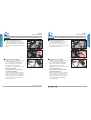
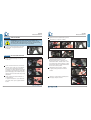
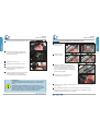
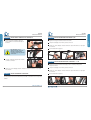
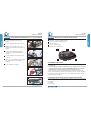
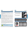
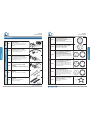
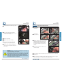
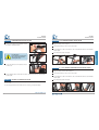
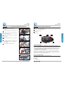
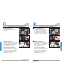
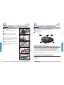
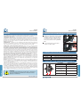
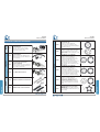
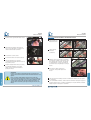
S03+ KIT
Manuale d’installazione
INDICE
ATTENZIONE
1. CONDIZIONI PER POTER MONTARE IL KIT S03+ SULLA BICICLETTA
5
Manuale d’installazione
Installation manual
Einbauanleitung
Manuel d’installation
2. CONDIZIONI PER POTER MONTARE LA BATTERIA
5
ITALIANO
ENGLISH
DEUTSCH
FRANÇAIS
3. COME VARIA LA LINEA CATENA DOPO IL MONTAGGIO DEL KIT S03+
5
4. ELENCO DEI COMPONENTI DISPONIBILI
6
5. INSTALLAZIONE DEL KIT S03+
STEP 1 - RIMOZIONE DELLE PARTI ORIGINALI
3-21
23-41
43-61
4
ITALIANO
S03+ KIT
10
10
STEP 2 - MISURARE E VERIFICARE IL MOZZO CENTRALE
11
STEP 2A - INSTALLAZIONE MOTORE PER MOZZI A PROFONDITÀ 70 mm
12
STEP 2B - INSTALLAZIONE MOTORE PER MOZZI A PROFONDITÀ 68 mm
13
STEP 3 - ANTI-ROTAZIONE
14
STEP 4 - FISSAGGIO DEL MOTORE
14
STEP 5 - INSTALLAZIONE DEL SENSORE VELOCITÀ
17
STEP 6 - INSTALLARE IL PANNELLO DI CONTROLLO
18
STEP 7 - INSTALLAZIONE DELLA BATTERIA
18
STEP 7A - INSTALLAZIONE DELLA BATTERIA 2,5 Ah
19
STEP 7B - INSTALLAZIONE BATTERIA CENTRALE 9 / 11 Ah
19
STEP 7C - INSTALLAZIONE DELLA BATTERIA DA 9 / 11 / 16 Ah POSTERIORE
20
STEP 8 - VERIFICATE LA CORRETTA INSTALLAZIONE
21
63-81
• Braking-Sunstar S.p.A. si riserva di modificare il contenuto del
presente manuale senza preavviso.
• La Versione aggiornata sarà eventualmente disponibile su
www.sunstaribike.com.
• Sul sito troverete inoltre informazioni sugli altri prodotti IBIKE ed
il catalogo ricambi.
www.sunstaribike.com
2
3
S03+ KIT
Manuale d’installazione
1. CONDIZIONI PER POTER MONTARE IL KIT S03+ SULLA BICICLETTA
ITALIANO
Leggete attentamente le istruzioni riportate nel presente manuale. Questo manuale è parte integrante
del prodotto e deve essere conservato in un luogo sicuro per future consultazioni.
COMPETENZE MECCANICHE - La maggior parte delle operazioni da effettuare sulle biciclette
per applicare il Kit S03+ richiedono formazione specifica, competenze sul prodotto, esperienza e
attrezzatura adeguata. La semplice attitudine alla meccanica potrebbe non essere sufficiente per operare
correttamente sulla bicicletta nelle operazioni di installazione del Kit S03+. Se avete dubbi sulla vostra
capacità di effettuare tali operazioni, rivolgetevi al personale specializzato BRAKING-SUNSTAR S.p.A.
USO DESIGNATO - Questo prodotto è stato progettato e fabbricato per essere usato sulla più ampia
tipologia di biciclette in commercio. È possibile che per particolari tipologie di telaio, molto differenti
dagli standard esistenti, non sia possibile montare il prodotto.
CICLO VITA - USURA - NECESSITÀ DI ISPEZIONE - Il ciclo vita dei componenti dipende da
molti fattori, quali ad esempio il peso dell’utilizzatore e le condizioni di utilizzo. Urti, Colpi, cadute
e più in generale un uso improprio, possono compromettere l’integrità strutturale dei componenti
riducendone enormemente il ciclo vitale; alcuni componenti sono soggetti ad usurarsi nel tempo. Vi
preghiamo di comunicare ai vostri clienti di far ispezionare regolarmente la bicicletta, per controllare
che vi siano cricche, deformazioni, indicazioni di fatica o usura. Se l’ispezione evidenziasse qualsiasi
deformazione, cricca o segni di usura, non importa quanto piccoli, sostituite immediatamente il
componente. Anche i componenti eccessivamente usurati devono essere immediatamente sostituiti.
Se l’utente pesa più di 80kg, dovete prevedere di ispezionare regolarmente la sua bicicletta per
controllare che non vi siano cricche, deformazioni, indicazioni di fatica o usura.
AVVISO IMPORTANTE SU PRESTAZIONI, SICUREZZA E GARANZIA - I componenti IBIKE
sono progettati per essere un unico sistema integrato. Per non compromettere la SICUREZZA,
le PRESTAZIONI, la LONGEVITÀ, la FUNZIONALITÀ e per non invalidare la GARANZIA, utilizzate
esclusivamente le parti ed i componenti forniti o specificati da BRAKING-SUNSTAR S.p.A. senza
interfacciarli o sostituirli con prodotti, parti o componenti fabbricati da altre aziende.
NOTA: Utensili forniti da altri produttori per componenti simili potrebbero non essere compatibili con i
componenti IBIKE. Verificate sempre con BRAKING-SUSNTAR S.p.A. o con il fabbricante dell’utensile la
corretta compatibilità prima di utilizzare gli utensili di un fabbricante sui componenti di un altro fabbricante.
È necessario evidenziare espressamente all’utilizzatore di questo prodotto BRAKING-SUNSTAR
S.p.A. che l’uso della bicicletta può comportare dei rischi che includono la rottura di un componente
della bicicletta, come pure altri rischi, dando luogo ad incidenti, lesioni fisiche o morte. Acquistando
e utilizzando questo prodotto BRAKING-SUNSTAR S.p.A. l’utilizzatore accetta espressamente,
volontariamente e coscientemente e/o assume tali rischi e accetta di non imputare alla BRAKINGSUNSTAR S.p.A. la colpa di qualsiasi danno che ne potrebbe derivare. Se avete qualsiasi domanda
vi preghiamo di contattare BRAKING-SUNSTAR S.p.A. per ottenere ulteriori informazioni.
1 Verificare che il supporto del movimento
centrale abbia un diametro compreso tra 33,8
e 34,2 mm.
Nel caso in cui l’interno del mozzo sia
deformato o siano presenti degli oggetti o
parti di telaio, non è possibile il montaggio
del power kit S03+.
1
ITALIANO
ATTENZIONE!
S03+ KIT
Manuale d’installazione
2
2 Il mozzo inferiore deve avere una larghezza
compresa tra 68 e 70 mm.
2. CONDIZIONI PER POTER MONTARE LA BATTERIA
MODELLO
CONDIZIONI
Sotto Sella
Dimensioni del canotto sella
Centrale
Predisposizione per il montaggio del supporto borraccia
Portapacchi Posteriore
Il telaio ha la predisposizione per montare il portapacchi posteriore
3. COME VARIA LA LINEA CATENA DOPO IL MONTAGGIO DEL KIT S03+
ATTENZIONE
La mancata osservanza delle istruzioni presenti in questo manuale
può causare danni al prodotto, incidenti, lesioni fisiche o morte.
A
CORONA
OFFSET A [mm]
Corona 41T
46.6
Corona 48T
53
Corona 41T
con ragno
48
Corona in AL 39T
con ragno
56.7
Corona in AL 52T
con ragno
56.7
www.sunstaribike.com
4
5
S03+ KIT
Manuale d’installazione
KB0001
Anti-rotazione
KB0002
KB0003
KB0044
KB0007
CORONA 41T STAMPATA CON VITI
(Sistema corona adatto a biciclette con ruote
maggiori di 22” con copricatena. Corona in
acciaio, paracatena in plastica, viti fissaggio
incluse)
KB0008
CORONA CNC 39T NERA
CON PROTEZIONE E VITI
(Sistema corona da utilizzare in abbinamento
al ragno KB0010 e raccomandato per
applicazioni con ruote maggiori di 22”
senza copricatena e con cambio interno al
mozzo ruota posteriore. Corona in alluminio
anodizzata nera FSA, paracatena in alluminio,
viti di fissaggio incluse)
KB0009
CORONA CNC 52T NERA
CON VITI E PROTEZIONE
(Sistema corona da utilizzare in abbinamento
al ragno KB0010 e raccomandato per
applicazioni con ruote fino a 20” senza
paracatena e con cambio interno al mozzo
ruota posteriore. Corona in alluminio
anodizzata nera FSA, paracatena in alluminio,
viti di fissaggio incluse)
KB0039
CORONA 41T STAMPATA CON VITI
(Sistema corona da utilizzare in abbinamento
al ragno KB0010 e raccomandato per
applicazioni con ruote maggiori di 22” senza
copricatena e con cambio esterno. Corona
in acciaio, paracatena in alluminio, viti di
fissaggio incluse)
KB0010
RAGNO DI FISSAGGIO CORONE NERO
CON VITI
(Da utilizzare con corone KB0039, KB0008,
KB0009. alluminio anodizzato nero FSA, viti di
fissaggio incluse)
S03+ KIT MOTORE
(Sono inclusi: pannello di comando, sensore
velocità, lamierini e minuteria per il corretto
montaggio)
ANTI ROTAZIONE PER IL CANOTTO
CENTRALE
(Adatto per applicazioni MTB perché
mantiene il motore in posizione anteriore con
la maggiore distanza dal terreno)
ANTI ROTAZIONE PER SUPPORTO
CAVALLETTO CENTRALE
(Adatto per applicazioni CITY; mantiene
il motore in posizione centrale/posteriore
fissandosi al carro posteriore)
KIT COMPLETO ANTIROTAZIONE
LEVE SX & DX CROMATE
Leve
KB0004
KB0006
CORONA 48T STAMPATA
CON PROTEZIONE E VITI
(Sistema corona adatto per biciclette con
ruote fino a 20” senza copricatena. Corona in
acciaio, paracatena in plastica, viti fissaggio
incluse)
Corone
Motore
ITALIANO
4. ELENCO DEI COMPONENTI DISPONIBILI
ITALIANO
S03+ KIT
Manuale d’installazione
KB0005
LEVE SX & DX NERE
www.sunstaribike.com
6
7
KB0051
KB0014
KB0015
Portabatteria
BATTERIA DA USARE IN
COMBINAZIONE CON
IL PORTABATTERIA KB0037
E IL CARICABATTERIA KB0036
(centrale a borraccia; 9 Ah;
percorrenza massima 54 km)
BATTERIA DA USARE IN
COMBINAZIONE CON
IL PORTABATTERIA KB0037
E IL CARICABATTERIA KB0036
(centrale a borraccia; 11 Ah;
percorrenza massima 60 km)
BATTERIA DA USARE IN
COMBINAZIONE CON
IL PORTABATTERIA KB0041
E IL CARICABATTERIA KB0036
(posteriore a portapacchi; 11 Ah;
percorrenza massima 60 km)
Caricabatteria
Batterie
Sistema batteria
KB0035
BATTERIA DA USARE IN
COMBINAZIONE CON
IL PORTABATTERIA KB0018
E IL CARICABATTERIA KB0016
(sottosella; 2,5 Ah;
percorrenza massima 20 km)
Sistema batteria
ITALIANO
KB0011
S03+ KIT
Manuale d’installazione
BATTERIA DA USARE IN
COMBINAZIONE CON
IL PORTABATTERIA KB0022
E IL CARICABATTERIA KB0017
(posteriore a portapacchi; 16 Ah;
percorrenza massima 95 km)
KB0018
ATTACCOBATTERIA
PER BATTERIA KB0011
(sottosella con cavo e chiave)
KB0037
ATTACCOBATTERIA PER
BATTERIA KB0035 E KB0051
(centrale a borraccia;
lunghezza 375mm)
KB0041
ATTACCOBATTERIA CON
PORTAPACCHI PER
BATTERIA KB0014
(posteriore a portapacchi)
KB0022
ATTACCOBATTERIA CON
PORTAPACCHI PER
BATTERIA KB0015
(posteriore a portapacchi)
KB0016
CARICA BATTERIA PER
BATTERIE KB0011 E KB0012
(110-240V - Uscita: 29V ÷ 1.75A)
KB0036
CARICA BATTERIA PER
BATTERIE KB0035, KB0051
E KB0014
(110-240V - Uscita: 29,4V ÷ 2A)
KB0017
CARICA BATTERIA PER
BATTERIA KB0015
(110-240V - Uscita: 29,4V ÷ 2A)
ITALIANO
S03+ KIT
Manuale d’installazione
www.sunstaribike.com
8
9
S03+ KIT
Manuale d’installazione
STEP 2
MISURARE E VERIFICARE IL MOZZO CENTRALE
ITALIANO
Misurare diametro e profondità del mozzo centrale.
1 DIAMETRO
Verificare che il supporto del movimento
centrale abbia un diametro compreso tra
33,8 e 34,2 mm.
Nel caso in cui l’interno del mozzo sia
deformato o siano presenti degli oggetti o
parti di telaio, non è possibile il montaggio del
power kit S03+.
Se sono presenti solamente delle bave del
telaio, è possibile effettuare la rimozione
utilizzando un alesatore o una lima.
STEP 1
1A
ITALIANO
5. INSTALLAZIONE DEL KIT S03+
S03+ KIT
Manuale d’installazione
1B
RIMOZIONE DELLE PARTI ORIGINALI
Sono necessarie chiavi e strumenti specifici per
rimuovere i componenti originali della bicicletta.
(estrattore, chiavi a tubo, chiave per smontare
movimento centrale specifico).
1
2 PROFONDITÀ
Il mozzo inferiore deve avere una larghezza
compresa tra 68 e 70 mm.
- Per una profondità di 70 mm
vedere le istruzioni al paragrafo 2A.
- Per una profondità di 68 mm
vedere le istruzioni al paragrafo 2B.
1 Rimuovere la pedivella sinistra.
2 Rimuovere la pedivella destra con la relativa
guarnitura. È possibile lasciare installato il
deragliatore anteriore per poter aver una
migliore posizione della catena.
2
3 Rimuovere il movimento centrale.
3
2
ATTENZIONE
Non utilizzate il martello per inserire il motore all’interno del mozzo
www.sunstaribike.com
10
11
S03+ KIT
Manuale d’installazione
INSTALLAZIONE MOTORE PER MOZZI A PROFONDITÀ 70 mm
ITALIANO
1 MOZZO A PROFONDITÀ 70 mm
In caso si utilizzi una bicicletta con mozzo
movimento centrale largo 70 mm non vi è
necessità di utilizzare lamierini aggiuntivi per
compensare le distanze ed allineare la linea
catena.
1A
STEP 2B
INSTALLAZIONE MOTORE PER MOZZI A PROFONDITÀ 68 mm
1 MOZZO A PROFONDITÀ 68 mm
In caso si utilizzi una bicicletta con mozzo
movimento centrale largo 68 mm è
necessario utilizzare i lamierini forniti.
Questi vanno posizionati in modo da adattare
correttamente la linea catena.
1B
2 MONTAGGIO COPRI-CATENA
Verificare lo spessore del supporto del copricatena che si aggancia sul mozzo.
Deve essere aggiunta una ranella di pari
spessore dietro l’attacco del lamierino
al motore (lato sx) per compensare
adeguatamente lo spessore del copri-catena.
1A
ITALIANO
STEP 2A
S03+ KIT
Manuale d’installazione
1B
2
2 MONTAGGIO COPRI-CATENA
Verificare lo spessore del supporto del copricatena che si aggancia sul mozzo.
Deve essere aggiunta una ranella di pari
spessore dietro l’attacco del lamierino
al motore (lato sx) per compensare
adeguatamente lo spessore del copri-catena.
2
NEL CASO IL MOTORE
SIA IN CONTATTO CON I BRACCETTI
POSTERIORI DEL TELAIO
Posizionare i lamierini forniti fino a quando il
motore non è più in contatto con il telaio.
Inserire lo stesso spessore dei lamierini tra
la piastra di fissaggio ed il motore (lato sx)
per compensare lo spazio utilizzato per
allontanarsi dal telaio.
www.sunstaribike.com
12
13
S03+ KIT
Manuale d’installazione
4 Agganciate il sistema di antirotazione previsto.
ANTI-ROTAZIONE
ITALIANO
ATTENZIONE - Il motore tende a ruotare con la rotazione dei
pedali. È obbligatorio fissare il motore al telaio con un accessorio
antirotazione! È possibile altrimenti prevedere una modifica al telaio
per predisporre un anti-rotazione meno ingombrante.
1 Scegliere il sistema antirotazione più adatto
alla bicicletta e alla posizione del motore
desiderata.
STEP 4
4A Antirotazione per supporto cavalletto.
ITALIANO
STEP 3
S03+ KIT
Manuale d’installazione
1
4B Antirotazione per canotto
FISSAGGIO DEL MOTORE
1 Inserite la piastra di fissaggio al telaio sul
movimento.
2 Inserite l’anello anti rotazione sul movimento
centrale. Questo anello può essere utilizzato
una sola volta a causa delle deformazioni
permanenti che subisce durante il montaggio.
Controllate la corretta posizione rispetto alla
piastra di fissaggio perché il dentino previsto
sull’anello deve incastrarsi nella sede prevista
sulla piastra.
3 Inserite la ghiera di chiusura verificando la
corretta direzione.
Lo spigolo stondato deve essere direzionato
verso il lato interno per accoppiarsi all’anelli
dentato.
1
5 Collegate provvisoriamente il motore alla
piastra di fissaggio attraverso le 2 viti
M6X20 date in dotazione e collegate anche
l’antirotazione definito. Chiudete le viti con una
pre-coppia in modo da poter stringere a coppia
le ghiere del movimento centrale mantenendo il
motore nella corretta posizione.
5
2
6 Utilizzando la chiave specifica, chiudete
a coppia (60Nm) la ghiera del movimento
centrale.
6
3
7 Chiudere a coppia (4 Nm) le viti della piastra
di fissaggio collegate al motore.
7
www.sunstaribike.com
14
15
S03+ KIT
Manuale d’installazione
STEP 5
9 Piegate l’aletta dell’anello antirotazione in
modo che possa incastrarsi sulla ghiera di
chiusura del movimento.
9
10 Agganciate la corona scelta.
12
11 Agganciate la catena alla nuova corona.
12 Fissate le pedivelle ed il relativo cappuccio
facendo attenzione al corretto verso e
corretta posizione.
13 Regolate il cambio (ove presente) per garantire
il corretto allineamento della catana ed il
corretto funzionamento nel passaggio marcia.
ATTENZIONE
La mancata regolazione del cambio posteriore (ove presente) può
causare il malfunzionamento del motore S03+ e la rottura dello
stesso.
Consigliamo, prima di utilizzare la bicicletta, di verificare che
l’escursione totale del cambio non faccia cadere la catena sopra
il pignone più grande, o sotto il pignone più piccolo. È necessario
inoltre regolare la tensione del cavo del cambio agendo sul
tensiometro, per regolare il corretto passaggio marcia.
INSTALLAZIONE DEL SENSORE VELOCITÀ
1 Fissate il magnete
sul raggio ruota.
1A
1B
2 Fissate il sensore
al carro posteriore.
2A
2B
ITALIANO
8
ITALIANO
8 Stringere le viti del sistema antirotazione scelto.
S03+ KIT
Manuale d’installazione
3 Adattate correttamente la posizione del
magnete e del sensore. La distanza tra i due
deve essere compresa tra 5 e 8 mm. In caso
il sensore sia mal posizionato, il motore non
riesce a rilevare la velocità e non sarà fornita
assistenza alla pedalata.
3
4 Collegate il sensore velocità al relativo
connettore previsto sul motore.
4
5 Legate con cura il cablaggio al telaio evitando che questo interferisca con gli organi
in movimento.
6 A fine installazione verificate il corretto posizionamento del sensore: provate la
bicicletta con una marcia bassa. Se la velocità massima raggiungibile è ridotta,
adattate la posizione del sensore e del magnete.
www.sunstaribike.com
16
17
S03+ KIT
Manuale d’installazione
INSTALLARE IL PANNELLO DI CONTROLLO
ITALIANO
1 Fissate il pannello al manubrio attraverso
le due viti M3x10 e la relativa staffa data in
dotazione.
1A
STEP 7A
INSTALLAZIONE DELLA BATTERIA 2,5 Ah
1 Agganciare il supporto batteria al canotto del sellino.
ITALIANO
STEP 6
S03+ KIT
Manuale d’installazione
2 Collegare il cablaggio al connettore previsto sul motore.
3 Legate con cura il cablaggio al telaio evitando che questo interferisca con gli organi
in movimento.
Fate attenzione a non
applicare troppa coppia che
potrebbe compromette il
corretto fissaggio del pannello
al manubrio.
2 Collegate il cablaggio del pannello al relativo
connettore sul motore.
4 Inserire la batteria nel supporto.
1B
1
2
4
2
STEP 7B
INSTALLAZIONE BATTERIA CENTRALE 9 / 11 Ah
1 Agganciare il supporto batteria al fissaggio previsto sul telaio per alloggiare il
supporto borraccia.
3 Legate con cura il cablaggio al telaio evitando che questo interferisca con gli organi
in movimento.
STEP 7
INSTALLAZIONE DELLA BATTERIA
2 Collegare il cablaggio al connettore previsto sul motore.
3 Legate con cura il cablaggio al telaio evitando che questo interferisca con gli organi
in movimento.
4 Inserire la batteria nel supporto.
Sono previste differenti tipologie di batteria.
Qui di seguito potete trovare le indicazioni per installare correttamente la vostra specifica
batteria.
1
2
4
www.sunstaribike.com
18
19
S03+ KIT
Manuale d’installazione
INSTALLAZIONE DELLA BATTERIA DA 9 / 11 / 16 Ah POSTERIORE
ITALIANO
1 Smontare il portapacchi posteriore ove
previsto.
2
VERIFICATE LA CORRETTA INSTALLAZIONE
1 Pulsante M - Selezione modalità assistenza
2 LED E, N, T di stato modalità impostata
3 LED stato di carica
4 Pulsante ON di accensione
2 Montare il supporto batteria al portapacchi.
3 Installare il nuovo portapacchi posteriore
sulla bicicletta ed avvitare le relative staffe di
aggancio.
STEP 8
ITALIANO
STEP 7C
S03+ KIT
Manuale d’installazione
5 Pulsante OFF di spegnimento 45
1
3
2
3
4 Montare gli eventuali fanalini già previsti
in dotazione ed agganciati al portapacchi
originale.
5 Collegare il cablaggio al connettore previsto
sul motore.
3
4
6 Legate con cura il cablaggio al telaio evitando
che questo interferisca con gli organi in
movimento.
5
AZIONAMENTO DEL SISTEMA
7 Inserire la batteria nel supporto.
• Solo per batteria 9 e 11 Ah centrale - Verificare che il tasto della batteria sia sulla
posizione ON.
• Solo per la batteria da 16Ah - Se la batteria non viene utilizzata per più di 7 giorni,
si imposta automaticamente la modalità RISPARMIO ENERGIA. Per riattivare la
batteria bisogna premere il pulsante posteriore per più di 2 secondi.
4
Premere Il tasto ON. Il sistema si avvia ed effettua l’autocontrollo per la verifica dello
stato di carica della batteria. Il sistema si trova sempre dopo l’avvio nel modo NORMAL.
Per spegnere il sistema premere il tasto OFF. Dopo 5 minuti senza comando il sistema si
spegne automaticamente da solo.
7
SCEGLIERE LA TIPOLOGIA DI SUPPORTO FORNITO DAL MOTORE
Premere il pulsante MODE per configurare il tipo di supporto che deve essere fornito dal
motore. Ci sono tre possibili modalità da impostare:
N = NORMAL
T = TURBO
E = ECONOMY
www.sunstaribike.com
20
21
S03+ KIT
Installation manual
INDEX
24
1. THE CONDITION TO INSTALL THE S03+ KIT ON THE BICYCLE
25
2. THE CONDITION FOR BATTERY INSTALLATION
25
3. HOW IS CHANGING CHAIN LINE AFTER S03+ KIT INSTALLATION
25
4. PARTS LIST
26
5. S03+ KIT INSTALLATION
30
STEP 1 - REMOVAL OF THE ORIGINAL BIKE PARTS
30
STEP 2 - MEASURE THE BOTTOM BRACKET SEAT
31
STEP 2A - MOTOR INSTALLATION FOR BOTTOM BRACKET WIDTH 70 mm
32
STEP 2B - MOTOR INSTALLATION FOR BOTTOM BRACKET WIDTH 68 mm
33
STEP 3 - ROTATION STOPPER
34
STEP 4 - MOTOR UNIT FIXING
34
STEP 5 - SPEED SENSOR INSTALLATION
37
STEP 6 - HUMAN INTERFACE INSTALLATION
38
STEP 7 - BATTERY SYSTEM INSTALLATION
38
STEP 7A - 2,5 Ah SADDLE BATTERY INSTALLATION
39
STEP 7B - 9 / 11 Ah CENTRAL DOWNPIPE BATTERY INSTALLATION
39
STEP 7C - 9 / 11 / 16 Ah REAR RACK BATTERY INSTALLATION
40
STEP 8 - VERIFY CORRECT INSTALLATION
41
ENGLISH
WARNING
• Braking-Sunstar S.p.A. reserves to modify the content of this
manual without notice.
• The updated version will always be available on
www.sunstaribike.com.
• On the website you will also find information on the other IBIKE
products and the spare parts catalogue.
23
S03+ KIT
Installation manual
1. THE CONDITION TO INSTALL THE S03+ KIT ON THE BICYCLE
Carefully read, follow and understand the instructions given in this manual. It is an essential part of
the prodcut, and you should keep it in a safe place for future reference.
MECHANIC QUALIFICATION - Please be advised that the installation of the S03+ Kit require
specialized knoledge, tools and experience. General mechanical attitude may not be sufficient to
properly install the S03+ Kit. If you have any doubt whatsoever regarding your service / ability, please
contact BRAKING-SUNSTAR S.p.A.
INTENDED USE - This product is designed and manufactured in order to be used on most number of
bicyles. In any case could be possible that special frames, different from standards, could not mount
correctly the S03+ Kit.
ENGLISH
LIFESPAN - WEAR - INSPECTION REQUIREMENT - The lifespan of the IBIKE components depends
on many factors, such as rider size and riding conditions. Impacts, falls, improper use or harsh use
in general may compromise the structural integrity of the components and significantly reduce their
lifespan. Some components are also subjected to wear over time. Please advice your final customers
that you have to regularly inspect the complete bicycle in order to check any cracks, deformation, signs
of fatigue or wear. If the inspection reveals any deformation, cracks, impact marks or stress marks, no
metter how slight, immediatly replace the component; components that have experienced excessive
wear also need immediate replacement. If the final user weigh more than 80 kg (100 kg user+bike), you
have to define a frequent and regular inspection schedule in order to check deformation, cracks,
impact marks or stress marks
IMPORTANT NOTICE: PERFORMANCE, SAFETY AND WARRANTY - The IBIKE components are
designed as a single integrated system. To avoid compromises in terms of SAFETY, PERFORMANCE,
DURABILITY, FUNCTION, and to prevent voiding the WARRANTY, use only parts and components
supplied or specified by BRAKING-SUNSTAR S.p.A. without interfacing them with or substituting
them with parts or components manufactured by other companies.
NOTE: Tools supplied by other manufacturers for components similar to IBIKE components may not
be compatible. Always check with BRAKING-SUNSTAR S.p.A. or the tool manufacturer to insure
compatibility before using tools supplied by one manufacturer on components supplied by another.
It’s important to highlight to the final user of the S03+ Kit that there are risks inherent in bibycle riding,
icluding but not limited to the risks that a component of the bicycle can fail, resulting in an accident,
personal injury or death. By his purchase and use of this BRAKING-SUNSTAR S.p.A. product, the
user expressly, voluntarily and knowingly accepts and assumes these risks, included but not limited
to the risk of passive or active neglicence of BRAKING-SUNSTAR S.p.A. or hidden, latent or obvious
defects in the product, and agrees to hold BRAKING-SUNSTAR S.p.A. harmless to the fullest extent
permitted by law against any resulting damages. If you have any questions, please contact BRAKINGSUNSTAR S.p.A. for additional information.
1 Verify that the bottom bracket diameter is
included between 33,8 and 34,2 mm.
In case the bottom bracket is deformed
or there are frame parts inside the bottom
bracket, it’s not possible to install the S03+ kit.
1
2 The bottom bracket must have a width
between 68 and 70 mm. Different cases
have to be carefully evaluated.
2
ENGLISH
WARNING!
S03+ KIT
Installation manual
2. THE CONDITION FOR BATTERY INSTALLATION
TYPE
CONDITION
Saddle
Saddle pipe diameter.
Central
Main frame arranged with bottle holder mounting ports.
Rear Rack
Frame with rear rack mounting ports.
3. HOW IS CHANGING CHAIN LINE AFTER S03+ KIT INSTALLATION
WARNING
Do not following these instruction may cause failure of the product,
accidents, personal injury or death.
A
FRONT SPROCKET
OFFSET A [mm]
41T RING
46.6
48T RING
53
41T RING
with spider
48
39T AL RING
with spider
56.7
52T AL RING
with spider
56.7
www.sunstaribike.com
24
25
S03+ KIT
Installation manual
S03+ KIT
Installation manual
Rotation Stopper
ENGLISH
KB0002
KB0003
KB0044
RING SYSTEM FOR BICYCLE
APPLICATIONS WITH WHEEL UP TO 20”
WITHOUT CHAIN COVER
(steel sprocket, plastic guard, includes bolts)
KB0007
RING SYSTEM FOR BICYCLE
APPLICATIONS WITH WHEEL LARGER
THAN 22” AND CHAIN COVER
(steel sprocket, includes bolts)
KB0008
RING SYSTEM USED IN COMBINATION
WITH THE SPIDER (KB0010) and
recommended for bicycle applications with
wheel larger than 24” without chain cover
and with internal hub gear system (fsa black
anodysed alumnium sprocket & chain guard,
includes bolts)
KB0009
RING SYSTEM USED IN COMBINATION
WITH THE SPIDER (KB0010) and
recommended for bicycle applications with
wheel up to 20” without chain cover (fsa
black anodysed alumnium sprocket & chain
guard, includes bolts)
KB0039
RING SYSTEM USED IN COMBINATION
WITH THE SPIDER (KB0010) and
recommended for bicycle applications with
wheel larger than 24” without chain cover and
with external gear system (steel sprocket,
fsa black anodysed alumnium chain guard,
includes bolts)
KB0010
SPIDER TO BE USED WITH CHAIN RING
KB0039, KB0008, KB0009
(Fsa Black Anodysed Aluminium,
Includes Bolts)
S03+ MOTOR KIT
(Included: control panel, speed sensor,
fixing plates & small parts for the correct
installation)
DOWNPIPE ROTATION STOPPER
(For mtb applications. motor is rotated
frontward in highest position)
CHAIN STAY ROTATION STOPPER
(For city applications. motor is in central or
backward position. to be used in frames
equipped with chain stay)
KIT OF BOTH ROTATION STOPPER
SOLUTIONS.
RECOMMENDED FOR FIRST APPROACH
CRANK SET
(Chrome steel, includes nuts and caps)
KB0005
CRANK SET
(Fsa black anodysed aluminium,
includes nuts and caps)
Crank
KB0004
ENGLISH
KB0001
KB0006
Ring
Motor Unit
4. PARTS LIST
www.sunstaribike.com
26
27
S03+ KIT
Installation manual
KB0051
KB0014
KB0015
BATTERY TO BE USED
IN COMBINATION WITH
HANGER KB0037
AND CHARGER KB0036
(bottle holder type; 11 Ah;
up to 60 km of range)
BATTERY TO BE USED
IN COMBINATION WITH
HANGER KB0041
AND CHARGER KB0036
(rear rack type; 11 Ah;
up to 54 km of range)
BATTERY TO BE USED
IN COMBINATION WITH
HANGER KB0022
AND CHARGER KB0017
(rear rack type; 16 Ah;
up to 95 km of range)
KB0018
HANGER FOR BATTERY KB0011
(saddle holder type)
KB0037
HANGER FOR BATTERY KB0035
(bottle holder type; 375 mm)
KB0041
HANGER FOR BATTERY KB0014
(rear rack type)
KB0022
HANGER FOR BATTERY KB0015
(rear rack type)
KB0016
CHARGER FOR BATTERIES
KB0011 AND KB0012
(110-240V - Output: 29V ÷ 1.75A)
KB0036
CHARGER FOR BATTERY
KB0035, KB0051
AND KB0014
(110-240V - Output: 29,4V ÷ 2A)
KB0017
CHARGER FOR BATTERIES
KB0013 AND KB0015
(110-240V - Output: 29,4V ÷ 2A)
ENGLISH
Hanger
BATTERY TO BE USED
IN COMBINATION WITH
HANGER KB0037
AND CHARGER KB0036
(bottle holder type; 9 Ah;
up to 54 km of range)
Charger
Batteries
Battery System
ENGLISH
KB0035
BATTERY TO BE USED
IN COMBINATION WITH
HANGER KB0018
AND CHARGER KB0016
(saddle holder type; 2,5 Ah;
up to 20 km of range)
Battery System
KB0011
S03+ KIT
Installation manual
www.sunstaribike.com
28
29
S03+ KIT
Installation manual
STEP 2
MEASURE THE BOTTOM BRACKET SEAT
Measure the bottom bracket diameter and width.
ENGLISH
1 DIAMETER
Verify that the bottom bracket diameter is
included between 33,8 and 34,2 mm.
In case the bottom bracket is deformed
or there are frame parts inside the bottom
bracket, it’s not possible to install the
S03+ Kit.
If inside bottom bracket there are only burrs,
it’s possible to remove them using an holesaw
or a reamer.
STEP 1
1A
1B
ENGLISH
5. S03+ KIT INSTALLATION
S03+ KIT
Installation manual
REMOVAL OF THE ORIGINAL BIKE PARTS
Special tools are required in order to remove
original bike components (puller, wrench,
spanner to remove the specific bottom bracket).
1
2 WIDTH
The bottom bracket must have a width
between 68 and 70 mm. Different cases have
to be carefully evaluated.
- If the bottom bracket width is 70 mm,
read information at paragraph 2A.
- If the bottom bracket width is 68 mm
read information at paragraph 2B.
1 Remove left cranck
2 Remove right cranckset. It’s possible to leave
mounted the front derailleurs in order to
mantain a more alligned chain position.
2
3 Remove original bottom bracket parts.
3
2
WARNING
Do not use hammer to insert motor inside bottom bracket.
www.sunstaribike.com
30
31
S03+ KIT
Installation manual
MOTOR INSTALLATION FOR BOTTOM BRACKET WIDTH 70 mm
1 BOTTOM BRACKET 70 mm
If the bike has a bottom bracket width of
70mm, no need to use the shims you can find
into the kit box.
1A
STEP 2B
MOTOR INSTALLATION FOR BOTTOM BRACKET WIDTH 68 mm
1 BOTTOM BRACKET 68 mm
If the bike has a bottom bracket width of
68mm,it’s important to use the shims that you
can find into the kit box. These parts need
to be placed between frame and fixing plate
in order to adjust bottom bracket width and
adjust correctly chian line.
ENGLISH
1B
2 CHAIN COVER MOUNTING
INSTRUCTIONS
Verify the thickness of the fixing plate of the
chain cover that fix on the bottom bracket.
Need to add a washer of the same thickness
on the back of the fixing plate (Left side) in
order to compensate correctly the thickness
of the chain cover.
1A
1B
2
2 CHAIN COVER MOUNTING
INSTRUCTIONS
Verify the thickness of the fixing plate of the
chain cover that fix on the bottom bracket.
Need to add a washer of the same thickness
on the back of the fixing plate (Left side) in
order to compensate correctly the thickness
of the chain cover.
ENGLISH
STEP 2A
S03+ KIT
Installation manual
2
IF THE ENGINE IS IN CONTACT WITH
CHAINSTAY
Install the shims till the motor is not going to
touch again the frame.
Insert the same thickness using washers on
the back side of the fixing plate (Left side) in
order to compensate correctly the gap gained
between motor and frame.
IF THE ENGINE IS IN CONTACT WITH
CHAINSTAY
Install the shims till the motor is not going to
touch again the frame.
Insert the same thickness using washers on
the back side of the fixing plate (Left side) in
order to compensate correctly the gap gained
between motor and frame.
www.sunstaribike.com
32
33
S03+ KIT
Installation manual
4 Attached the rotation stopper to the motor unit.
ROTATION STOPPER
WARNING - Motor unit tend to rotate with the rotation of the pedals.
For this reason is absolutely important to fix the unit to the frame
with a rotation stopper accessory! It’s also possible to study a frame
port in order to apply a smaller rotation stopper.
ENGLISH
1 Select the rotation stopper that fix properly
to the bike. The rotation stopper have to be
fixed externally respect fixing plate.
STEP 4
4A Chainstay rotation stopper.
1
4B Downpipe rotation stopper.
ENGLISH
STEP 3
S03+ KIT
Installation manual
MOTOR UNIT FIXING
1 Apply on the bottom bracket the fixing plate.
1
5 Make a temporary joint between fixing plate
and motor using n 2 M6x20 screw provided
and connect also the antirotation selected.
Tight the screws with low torque in order
to mantain the correct final position while
tightening the central bottom bracket.
5
2 Insert chassis ring rotation stopper on the
bottom bracket. This ring can be used only
one time due to the permanent deformation
that the installation cause to it.
Check the correct position respect the
fixing plate because the small teeth must fit
correctly in its seat on the plate.
2
6 Use the specific tool in order to apply correct
torque (60Nm) on the fixing ring.
6
3 Insert the chassis fixing ring verifying the
correct direction.
The rounded edge must be directed toward
the inner side to mate chassis ring rotation
stopper.
3
7 Tighten the fixing plate bolt with a 4 Nm
torque.
7
www.sunstaribike.com
34
35
S03+ KIT
Installation manual
8
9 Fix one teeth of the fixing ring rotation
stopper in order to bend it inside one of the
grooves on the fixing ring.
9
10 Add the selected Ring.
12
STEP 5
11 Apply the chain on the new Ring.
12 Fix the new cranck and the related cap
verifying the correct side and position.
13 Adjust the Rear Derailleurs (if available) in
order to verify correct chain line and correct
gear change.
SPEED SENSOR INSTALLATION
1 Fix the magnet
to the wheel.
1A
1B
2 Fix the sensor
to the chain stay
2A
2B
3 Adjust the position of the sensor and magnet.
The distance between them must be kept
between 5 and 8 mm. If the sensor is in
wrong position, the motor will not evaluate
the real speed and will not assist the user
pedeling.
3
4 Connect the speed sensor cable to the one
on the motor side.
4
ENGLISH
ENGLISH
8 Verify and tighten the rotation stopper bolts.
S03+ KIT
Installation manual
WARNING
Failure to adjust the rear derailleur (if available) can cause engine
malfunction and failure of the S03+ Kit.
Braking-Sunstar SPA suggest, before start using the S03+, to verify
that the maximum movement of the rear derailleur do not allow the
chain to fall over the biggest sprocket or under the smaller one.
Furthermore it’s important to adjust the tension of the shift cable
acting on the tensiometer, in order to define the correct movement
of the derailleur between each sprocket.
5 Fix accuratly the cable on the frame in order to avoid that the harness can fall inside
rotation parts.
6 At the end verify the installation, testing the bike with a small sprocket. If the speed
that you can reach is too low, adjust sensor and magnet position.
www.sunstaribike.com
36
37
S03+ KIT
Installation manual
STEP 6
HUMAN INTERFACE INSTALLATION
1 Fix the control panel on the handlebar using 2
bolt M3x10 and related fixture.
S03+ KIT
Installation manual
STEP 7A
1A
2,5 Ah SADDLE BATTERY INSTALLATION
1 Apply the hanger on the seatpost.
2 Connect the harness to the one on the motor side.
3 Fix accurately the cable on the frame in order to avoid that the harness can fall inside
rotation parts
2 Connect the harness to the related connector
on the motor.
4 Insert the battery inside the hanger.
1B
1
2
4
ENGLISH
ENGLISH
Pay attention!!
Do not apply too much torque
that could compromise the
control panel case.
2
STEP 7B
9 / 11 Ah CENTRAL DOWNPIPE BATTERY INSTALLATION
1 Apply the hanger on the bottle-holder port.
3 Fix accuratly the cable on the frame in order to avoid that the harness can fall inside
rotation parts.
STEP 7
BATTERY SYSTEM INSTALLATION
2 Connect the harness to the one on the motor side.
3 Fix accurately the cable on the frame in order to avoid that the harness can fall inside
rotation parts.
4 insert the battery inside the hanger.
The S03+ Kit can fit different dimension and position of S03+ batteries developed with
the motor unit.
On the next pages there are the instruction to fit correctly your specific battery.
1
2
4
www.sunstaribike.com
38
39
S03+ KIT
Installation manual
STEP 7C
9 / 11 / 16 Ah REAR RACK BATTERY INSTALLATION
1 Disassemble the original rear rack (if
available).
2
STEP 8
VERIFY CORRECT INSTALLATION
1 M Button: Select assisting mode
2 LED E, N, T: Selected assisting mode.
3 LED for charge status
4 ON button
2 Mount the battery hanger on the rear rack.
5 OFF button
3 Install the new rack on the bike and tight the
related fixing brackets.
4 Apply the lights available on the original rack
(if available).
S03+ KIT
Installation manual
1
3
2
3
6 Fix accuratly the cable on the frame in order
to avoid that the harness can fall inside
rotation parts.
3
4
ENGLISH
ENGLISH
5 Connect the harness to the one on the motor
side.
5
7 insert the battery inside the hanger.
START THE SYSTEM
• Only for central downpipe 9 / 11 Ah battery - Verify that the battery button is on
ON position.
• Only for 16Ah batteries - If the battery is stocked more than 7days, it goes into
Energy safety mode; in order to reactivate the battery it’s needed to press rear
reset button for more than 2 seconds.
4
Press ON button on the control panel. The system start and motor control unit check
the entire system functionality. At the start of the system, the controller is always set on
NORMAL mode. To shut down the system press OFF button. After 5 minutes without
using the unit, the system automatically shut down.
7
SELECT ASSISTING MODE
Press mode button in order to select motor support mode.
There are 3 assisting modes:
N = NORMAL
T = TURBO
E = ECONOMY
www.sunstaribike.com
40
41
S03+ KIT
Einbauanleitung
ACHTUNG
44
1. GRUNDVORAUSSETZUNGEN ZUR INSTALLATION DES S03+ KITS
45
2. VORAUSSETZUNGEN DER BATTERIE-MONTAGE
45
3. KETTENLINIE NACH MONTAGE DES S03+ KITS
45
4. KOMPONENTENÜBERSICHT
46
5. INSTALLATION DES S03+ KITS
50
SCHRITT 1 - DEMONTAGE DER VEBAUTEN KOMPONENTEN
50
SCHRITT 2 - VERMESSUNG DES TRETLAGERS
51
SCHRITT 2A - MOTORMONTAGE FÜR TRETLAGERBREITE 70 mm
52
SCHRITT 2B - MOTOR MONTAGE FÜR TRETLAGERBREITE 68 mm
53
SCHRITT 3 - DREHMOMENTABSTÜTZUNG
54
SCHRITT 4 - MOTOR MONTAGE
54
SCHRITT 5 - MONTAGE DES GESCHWINDIGKEITSSENSORS
57
SCHRITT 6 - MONTAGE DER BEDIENEINHEIT
58
SCHRITT 7 - MONTAGE DES AKKUS
58
SCHRITT 7A - 2,5 Ah SATTEL AKKU MONTAGE
59
SCHRITT 7B - MONTAGE DES RAHMENAKKUS 9 Ah / 11 Ah
59
SCHRITT 7C - MONTAGE DES 9 / 11/ 16 Ah GEPÄCKTRÄGER AKKUS
60
SCHRITT 8 - ÜBERPRÜFUNG DER KORREKTEN MONTAGE
61
DEUTSCH
INDEX
• Braking-Sunstar S.p.A. behält sich vor, den Inhalt dieser
Bedienungsanleitung zu ändern, ohne dies zu veröffentlichen
• Die aktuellste Version dieser Anleitung finden Sie auf
www.sunstaribike.com.
• Auf der iBike Webseite bekommen Sie weitere Informationen zu
Produkten und Ersatzteilen.
43
S03+ KIT
Einbauanleitung
1. GRUNDVORAUSSETZUNGEN ZUR INSTALLATION DES S03+ KITS
Bitte lesen Sie diese Anleitung aufmerksam und befolgen Sie die Anweisungen. Diese Einbauanleitung
ist ein wichtiger Bestandteil Ihres Produktes. Bitte bewahren Sie dies an einem sicheren Ort auf für
eine spätere Verwendung.
MECHANISCHE KENNTNISSE - Wir weisen Sie darauf hin, dass der Einbau des iBike Nachrüstsatzes
spezielles Wissen, Werkzeuge und Erfahrungen voraussetzt. Ein gründsätzliches technisches
Verständnis kann ggfs. nicht aussreichen, um das iBike Kit vorschriftsmäßig und korrekt zu installieren.
Falls Sie irgendwelche Zweifel oder Fragen haben, kontaktieren Sie bitte Braking Sunstar S.p.A.
ANWENDUNGSBEREICH - Das S03+ Kit ist konzipiert für den Einbau an Fahrräder mit einem
Standard-Tretlager (BSA). In besonderen Fällen kann es z.B. durch besondere Rahmenformen
vorkommen, dass sich das S03+ Kit nicht einwandfrei einbauen lässt.
LEBENSDAUER-VERSCHLEISS-INSPEKTIONSINTERVALLE - Die Lebensdauer des S03+ Systems
ist abhängig von vielen Faktoren. Hierzu gehören die Nutzungsintensität, Stürze, Umwelteinflüsse und die
generelle Belastungsintensität durch den Nutzer des Systems. Diese Faktoren können die Lebensdauer
erheblich reduzieren. Einige Komponenten sind Verschleißteile, die eine begrenzte Lebensdauer
haben. Bitte weisen Sie den Endkunden darauf hin, dass das komplette Fahrzeug regelmäßig auf
Rahmenbrüche, Risse oder Beschädigungen, bzw. Verschleißerscheinungen untersucht wird. Falls im
Zuge der Inspektion Auffälligkeiten oder Beschädigungen irgendeiner Art in deutlich werden sollten,
müssen die betreffenden Komponenten umgehend ausgetauscht werden. Verschleißteile müssen
ebenfalls regelmäßig überprüft und ggfs. ausgetauscht werden. Falls der Endkunde, bzw. Nutzer des
Fahrzeugs mehr als 80 KG wiegen sollte, muss ein regelmäßiger Inspektionsplan erstellt werden zur
Überprüfung des Fahrzeugs auf Brüche oder Deformationen.
WICHTIGE INFORMATION: LEISTUNG, SICHERHEIT UND GARANTIE - Die Komponenten des
S03+ Systems sind konzipiert als ein geschlossenes, integriertes System. Um negative Einflüsse
auf die Sicherheit, Leistung, Haltbarkeit und Funktion, sowie den Verlust der Garantie zu vermeiden,
dürfen nur Komponenten oder Bauteile verwendet werden, die von Braking Sunstar SpA freigegeben
oder geliefert wurden.
DEUTSCH
ANMERKUNG: Werkzeuge anderer Hersteller die für ähnliche Komponenten wie dem S03+ System
verwendet werden, sind ggfs. nicht kompatibel. Bitte wenden Sie sich an Braking Sunstar SpA um die
Verwendbarkeit bestätigen zu lassen, bevor Sie dieses Werkzeug oder diese Komponente verwenden.
Es ist sehr wichtig, dem Endkunden oder Nutzer des S03+ Kits darauf hinzuweisen, dass Fahrradfahren
Risiken birgt. Beim Versagen von Komponenten am Fahrrad können Unfälle, Personenschäden oder
auch der tödliche Verletzungen die Folge sein. Mit dem Kauf und der Verwendung dieses Produktes,
erklärt sich der Nutzer ausdrücklich, freiwillig und wissentlich dazu bereit, diese Risiken zu akzeptieren,
soweit diese nicht auf eine passive oder aktive Fahrlässigkeit oder einen versteckten, latenten oder
offensichtlichen Mangel des Produktes von Braking Sunstar SpA zurückzuführen sind. Weiter erklärt
sich der Kunde dazu bereit Braking Sunstar SpA schadlos zu halten, soweit dies mit den geltenden
gesetzlichen Regelungen konform geht. Wenn Sie dazu weitere Fragen haben, wenden Sie sich bitte an
Braking Sunstar SpA.
1 Überprüfen Sie den Durchmesser des
Tretlagers. Dieser muss zwischen 33,8 und
34,2mm sein.
Falls sich im Tretlager Beschädigungen oder
innenliegende Rahmenteile befinden, kann
das iBike Kit NICHT installiert werden.
2 Die Breite des Tretlagers muss zwischen
68mm und 70mm liegen. Abweichende
Breiten müssen sorgfältig überprüft
werden.
1
2
2. VORAUSSETZUNGEN DER BATTERIE-MONTAGE
MONTAGETYP
RAHMENBEDINGUNG
Sattel
Sattelrohrduchmesser
Zentral / Rahmen
Rahmenform und Position der Flaschenhaltergewinde
Gepäckträger
Rahmen / Bohrungen der Gepäckträgerstreben
DEUTSCH
ACHTUNG!
S03+ KIT
Einbauanleitung
3. KETTENLINIE NACH MONTAGE DES S03+ KITS
WARNUNG
Nichtbeachtung dieser Anleitung, kann zu Produktausfällen,
Unfällen, Personenschäden oder zum Tod führen.
A
KETTENBLATT
VERSATZ - A [MM]
41T RING
46.6
48T RING
53
41T RING mit separater
Kettenblattaufnahme
48
39T AL RING mit separater
Kettenblattaufnahme
56.7
52T AL RING mit separater
Kettenblattaufnahme
56.7
www.sunstaribike.com
44
45
S03+ KIT
Einbauanleitung
S03+ KIT
Einbauanleitung
Rotation Stopper
KB0002
KB0003
DEUTSCH
KB0044
KETTENBLATT 48 ZÄHNE, GESTANZT MIT
HOSENSCHUTZ, SCHRAUBEN
(Empfohlen für Raddurchmesser bis 20 Zoll)
KB0007
KETTENBLATT 41 ZÄHNE, GESTANZT,
INKL. SCHRAUBEN
(Empfohlen für Verwendung an
Raddurchmesser >22 Zoll)
KB0008
KETTENBLATT 39 ZÄHNE; KOMBINIERBAR
MIT SPIDER (KB0010); SCHWARZ, INKL.
SCHRAUBEN UND SCHUTZRING
(Empfohlen für Raddurchmesser >24 Zoll)
KB0009
KETTENBLATT 52 ZÄHNE; KOMBINIERBAR
MIT SPIDER KB0010; SCHWARZ INKL.
SCHRAUBEN UND SCHUTZRING
(Empfohlen für Raddurchmesser bis zu 20 Zoll)
KB0039
KETTENBLATT 41 ZÄHNE;
KOMBINIERBAR MIT SPIDER KB0010;
GESTANZT INKL. SCHRAUBEN UND
SCHUTZRING
(Empfohlen für Raddurchmesser >24 Zoll)
KB0010
SPIDER FÜR DIE KOMBINATION
MIT DEN KETTENBLÄTTERN
KB0039, KB0008, KB0009
(inkl. Schrauben)
S03+ MOTOR KIT
(Beinhaltet: Display, Geschwindigkeitssensor,
Montagezubehör, Kleinteile zur korrekten
Montage)
DREHMOMENTABSTZÜTZUNG
UNTERROHR
(Verwendung am Unterrohr, wenn der Motor
maximal nach vorne gerichtet wurde bei der
Montage)
DREHMOMENTABSTÜTZUNG ZENTRAL
(Drehmomentabstützung für den Bereich
Tretlager, Kettenstrebe; Verwendung, wenn
der Motor in rückwärtiger Position verbaut
werden soll)
SET BESTEHEND AUS BEIDEN
DREHMOMENTABSTÜTZUNGEN
(Zentral und Unterrohr)
VERCHROMTE STAHLKURBEL
(inkl. Schrauben und Abdeckung)
KB0005
KURBEL ALUMINIUM
(FSA, schwarz, inkl. Schrauben und
Abdeckungen)
Crank
KB0004
DEUTSCH
KB0001
KB0006
Kettenblatt
Motor
4. KOMPONENTENÜBERSICHT
www.sunstaribike.com
46
47
AKKU
KB0051
KB0014
KB0015
Halter
AKKU ZUR NUTZUNG
IN VERBINDUNG MIT
BEFESTIGUNG KB0037
UND LADEGERÄT KB0036
(9 Ah)
AKKU ZUR NUTZUNG
IN VERBINDUNG MIT
BEFESTIGUNG KB0037
UND LADEGERÄT KB0036
(11 Ah)
AKKU ZUR NUTZUNG
IN KOMBINATION MIT
GEPÄCKTRÄGER KB0041
UND LADEGERÄT KB0036
(Gepäckträgerakku; 11AH;
ca. 54KM max. Reichweite)
Ladegeräte
DEUTSCH
Batterie System
KB0035
BATTERIE ZUR NUTZUNG
IN VEBINDUNG MIT
BEFESTIGUNG KB0018
UND LADEGERÄT KB0016
(2,5 Ah)
Batterie System
KB0011
S03+ KIT
Einbauanleitung
AKKU ZUR NUTZUNG MIT
GEPÄCKTRÄGERBEFESTIGUNG
KB0022 UND
LADEGERÄT KB0017
(16 Ah)
KB0018
BATTERIEBEFESTIGUNG
für 2,5 Ah Sattel-Akku KB0011
KB0037
BEFESTIGUNG FÜR AKKU
KB0035 UND AKKU KB0051
(Flaschenhalterbefestigung; 375mm)
KB0041
GEPÄCKTRÄGER ZUR
BEFESTIGUNG AKKU KB0014
KB0022
GEPÄCKTRÄGER ZUR
BEFESTIGUNG AKKU KB0015
KB0016
LADEGERÄT FÜR BATTERIE
KB0011 UND KB0012
(110-240V - Output: 29V ÷ 1.75A)
KB0036
LADEGERÄT FÜR AKKU KB0035,
KB0051 UND KB0040
(110-240V - Output: 29,4V ÷ 2A)
KB0017
LADEGERÄT FÜR NUTZUNG
MIT AKKU KB0015
(110-240V - Output: 29,4V ÷ 2A)
DEUTSCH
S03+ KIT
Einbauanleitung
www.sunstaribike.com
48
49
S03+ KIT
Einbauanleitung
SCHRITT 2
VERMESSUNG DES TRETLAGERS
Messen Sie die Breite und den Durchmesser des
Tretlagers.
SCHRITT 1
DEMONTAGE DER VEBAUTEN KOMPONENTEN
Spezialwerkzeug wird benötigt zur Demontage
der verbauten Komponenten (Kurbelabzieher,
Tretlageradapter; Innensechskant).
1
2 TRETLAGERBREITE
Das Tretlagergehäuse muss eine Breite
zwischen 68 und 70mm haben.
- Falls das Tretlagergehäuse 70 mm Breite
hat, lesen Sie bitte Schritt 2A.
- Falls das Tretlagergehäuse 68 mm Breite
hat, lesen Sie bitte Schritt 2B.
DEUTSCH
1 Entfernen Sie den linken Kurbelarm.
2 Entfernen Sie die rechte Kurbelgarnitur, Den
Umwerfer können Sie belassen, um die neue
Kettenlinie besser justieren zu können.
2
3 Entfernen Sie das verbaute Tretlager.
3
1 DURCHMESSER
Vergewissern Sie sich, dass das Tretlager einen
Durchmesser. Zwischen 33,8mm und 34,2mm
hat.
Falls das Tretlager Beschädigungen oder
innenliegende Rahmenteile aufweist, darf das
S03+ Kit NICHT verbaut werden.
Falls im Tretlagergehäuse nur leicht
Erhöhungen festgestellt werden, können diese
entfernt werden und das Kit kann verbaut
werden.
1A
1B
2
DEUTSCH
5. INSTALLATION DES S03+ KITS
S03+ KIT
Einbauanleitung
ACHTUNG
In keinem Fall darf der Motor mit einem Hammer in das
Tretlagergehäuse geschlagen werden.
www.sunstaribike.com
50
51
S03+ KIT
Einbauanleitung
MOTORMONTAGE FÜR TRETLAGERBREITE 70 mm
1 TRETLAGERBREITE 70 mm
Bei einer Tretlagerbreite von 70mm können
Sie die beigelegten Unterlegscheiben
verwenden.
1A
DEUTSCH
MOTOR MONTAGE FÜR TRETLAGERBREITE 68 mm
1 TRETLAGERAUFNAHME 68 mm
Im Falle einer Tretlagerbreite von 68 mm
ist es sehr wichtig, die Distanzscheiben
zu verwenden, die dem Kit beigefügt sind.
Diese Scheiben müssen zwischen dem
Tretlager und der Montageplatte des Motors
positioniert werden, um eine bestmögliche
Kettenlinie zu erreichen.
1B
2 MONTAGE KETTENSCHUTZ
Überprüfen Sie die Dicke der Aufnahme des
Kettenschutzkastens. Sie müssen dann auf
der linken Tretlagerseite eine Unterlegscheibe
mit der selben Stärke verwenden, um den
Motor am Gehäuse zu zentrieren.
SCHRITT 2B
2
2 MONTAGE KETTENKASTEN
Überprüfen Sie die Dicke der Aufnahme des
Kettenschutzkastens. Sie müssen dann auf
der linken Tretlagerseite eine Unterlegscheibe
mit der selben Stärke verwenden, um den
Motor am Gehäuse zu zentrieren.
1A
1B
2
DEUTSCH
SCHRITT 2A
S03+ KIT
Einbauanleitung
FALLS DER MOTOR GEGEN EINE
KETTENSTREBE STÖSST
Benutzen Sie Unterlegscheiben, bis der Motor
keinen Kontakt mehr zur Kettenstrebe hat.
Gleichen Sie auf der anderen (linken) Seite
mit Unterlegscheiben aus mit der gleichen
Stärke, um den Motor wieder korrekt am
Tretlagergehäuse zu zentrieren.
FALLS DER MOTOR GEGEN EINE
KETTENSTREBE STÖSST
Benutzen Sie Unterlegscheiben, bis der Motor
keinen Kontakt mehr zur Kettenstrebe hat.
Gleichen Sie auf der anderen (linken) Seite
mit Unterlegscheiben aus mit der gleichen
Stärke, um den Motor wieder korrekt am
Tretlagergehäuse zu zentrieren.
www.sunstaribike.com
52
53
S03+ KIT
Einbauanleitung
4 Befestigen Sie die Drehmomentabstützung am Motor.
DREHMOMENTABSTÜTZUNG
ACHTUNG
Der Motor neigt zu einer Rotationsbewegung nach in Richtung der
Pedalbewegung. Deshalb ist es sehr wichtig den Motor mittels einer
der beiliegenden Drehmomentabstützung zu fixieren.
1 Wählen Sie die Drehmomentabstützung aus,
die am besten zu Ihrer Einbausituation passt.
Die Montage muss fest mit dem Rahmen
erfolgen.
SCHRITT 4
1
4B Drehmomentabstützung am Unterrohr.
MOTOR MONTAGE
1 Stecken Sie das Fixierungselement auf die
Tretlagerachse des Motors.
2 Stecken Sie den Fixierungsring auf die
Tretlagerachse. Dieser Ring kann nur
einmalig verwendet werden, da dieser bei der
Montage deformiert werden muss.
Prüfen Sie die korrekte Positionierung
des Rings. Dieser muss mit einem Zahn
exakt in die vorgegebene Vertiefung des
Montageelements fixiert werden.
DEUTSCH
4A Drehmomentabstützung an der Kettenstrebe.
3 Stecken Sie nun die Überwurfmutter für
die Befestigung der Motoreinheit auf das
Tretlager des Motors.
Die abgerundete Seite muss zur Seite des
Fixierungsringes zeigen, bzw. zum Tretlager.
1
5 Stellen Sie eine vorläufige Verbindung
zwischen dem Motorgehäuse und dem
Montageelement her mittels der beigefügten
2x M6x20mm Schrauben. Schrauben nur
leicht anziehen, um den Motor noch in die
Endposition ausrichten zu können.
5
2
6 Die Überwurfmutter muss nun mit dem
Spezialwerkzeug mit 60 Nm! angezogen
werden.
6
3
7 Ziehen Sie nun die M6 Schrauben der
Montageplatte mit 4 Nm an.
7
DEUTSCH
SCHRITT 3
S03+ KIT
Einbauanleitung
www.sunstaribike.com
54
55
S03+ KIT
Einbauanleitung
8 Überprüfen und fixieren Sie die Schrauben der
jeweiligen Drehmonentabstützung.
9 Wichtig! Biegen Sie nun einen Zahn
des Fixierungsringes in eine Kerbe der
Überwurfmutter!
8
S03+ KIT
Einbauanleitung
SCHRITT 5
MONTAGE DES GESCHWINDIGKEITSSENSORS
1 Befestigen Sie das
Magnet an einer
Speiche.
1A
1B
2 Befestigen Sie den
Sensor an einer
Kettenstrebe.
2A
2B
9
10 Wählen Sie das passende Kettenblatt aus.
12
12 Befestigen Sie die beiden neuen Kurbeln.
Beachten Sie, dass der rechte und linke
Kurbelarm unterscheiden.
DEUTSCH
13 Stellen Sie ggfs. den hinteren Umwerfer auf die
neue Kettenlinie ein (falls erforderlich). Prüfen
und korrigieren Sie die Schaltgenauigkeit.
3 Justieren Sie den Abstand zwischen
Sensor und dem Magneten. Der Abstand
muss zwischen 5 und 8 mm betragen.
Falls der Sensor falsch positioniert wird,
regelt der Motor nicht bei der vorgegeben
Geschwindigkeit ab. (Pedelec 25 Km/h).
3
4 Verbinden Sie das Kabel des Sensor mit dem
vorgesehenen Kabel am Motor.
4
DEUTSCH
11 Befestigen Sie das Kettenblatt (bzw. den
Spider) am rechten Motorgehäuse.
ACHTUNG
Falls der hintere Umwerfer nicht korrekt justiert wird, kann es zu
Fehlfunktionen und Defekten am Motor kommen.Wir empfehlen
dringend vor Nutzung des S03+ Kits den Schwenkbereich des
Schaltwerks zu überprüfen! Bitte synchronisieren Sie auch das
Schaltwerk nach Montage des Kits neu, da ggfs. eine neue
Kettenlinie entstanden ist.
5 Fixieren Sie das Kabel am Rahmen um Schäden am Kabel oder des Steckers zu
vermeiden.
6 Bitte überprüfen Sie vor Fahrbeginn die korrekte Funktionsweise des
Geschwindigkeitessensors.
www.sunstaribike.com
56
57
S03+ KIT
Einbauanleitung
SCHRITT 6
MONTAGE DER BEDIENEINHEIT
1 Befestigen Sie die Bedieneinheit Am Lenker
mit 2 Schrauben (M3x10).
S03+ KIT
Einbauanleitung
SCHRITT 7A
1A
2,5 Ah SATTEL AKKU MONTAGE
1 Befestigen Sie den Halter am Sattelrohr.
2 Verbinden Sie das Kabel mit dem Batteriekabel des Motors.
3 Befestigen Sie das Kabel sorgfältig am Rahmen um Beschädigungen zu vermeiden.
4 Stecken Sie den Akku in den Halter.
Achtung! Die Schrauben
nicht zu fest anziehen.
Dies kann das Gehäuse der
Bedieneinheit beschädigen.
2 Verbinden Sie das Kabel mit dem korrekten
Kabel am Motor.
1B
1
2
4
2
SCHRITT 7B
MONTAGE DES RAHMENAKKUS 9 Ah / 11 Ah
3 Befestigen Sie das Kabel sorgfältig am Rahmen um Beschädigungen des Kabels zu
vermeiden.
SCHRITT 7
DEUTSCH
DEUTSCH
1 Befestigen Sie den Halter an den Aufnahmen des Flaschenhalters
2 Verbinden Sie das Kabel mit dem Batteriekabel des Motors.
3 Befestigen Sie das Kabel sorgfältig am Rahmen um Beschädigungen zu vermeiden.
4 Setzen Sie den Akku vorsichtig in die Halterung ein.
MONTAGE DES AKKUS
Sie können für das S03+ Kit verschiedene Batterietypen wählen, die speziell für das
S03+ Kit entwickelt wurden.
Auf den nächsten Seiten finden Sie die Anbauanleitungen für den jeweiligen Batterietyp.
1
2
4
www.sunstaribike.com
58
59
S03+ KIT
Einbauanleitung
SCHRITT 7C
MONTAGE DES 9 / 11/ 16 Ah GEPÄCKTRÄGER AKKUS
1 Demontieren Sie den alten Gepäckträger
(falls vorhanden).
2
S03+ KIT
Einbauanleitung
SCHRITT 8
ÜBERPRÜFUNG DER KORREKTEN MONTAGE
1 M Button: Knopf für Wechsel des Unterstützungsmodus
2 LED E, N, T: Anzeige für den gewählten Unterstützungsmodus
3 LED Ladezustand Akku
4 ON: System aktivieren
2 Montieren Sie die Akkubefestigung am
Träger.
5 OFF: System ausschalten
3 Befestigen Sie den neuen Gepäckträger
am Rad und montieren Sie die jeweiligen
Streben.
1
3
2
3
4 Montieren Sie das Rücklicht (falls vorhanden).
5 Verbinden Sie das Kabel der Akkuaufnahme
mit dem Batteriekabel des Motors.
6 Befestigen Sie sorgfältig das Kabel am
Rahmen.
3
4
5
7 Stecken Sie den Akku vorsichtig in die AkkuAufnahme des Halters.
• Nur für 9 / 11 Ah Akku: Der Akku muss angeschaltet werden (grüne LED).
• Nur für 16 Ah Akku: Falls der Akku für mehr als 7 Tage nicht angeschaltet wurde,
wird dieser in den Energiesparmodus geschaltet. Um den Akku zu aktivieren,
muss der hintere Knopf am Akku für min. 2 Sekunden gedrückt werden.
4
DEUTSCH
DEUTSCH
STARTEN SIE DAS S03+ SYSTEM
Drücken Sie die Taste ON auf der Bedieneinheit. Das System überprüft dann
automatisch den Systemstatus. Das System immer im Unterstützungsmodus NORMAL.
Um das System auszuschalten, drücken Sie die OFF Taste.Nach 5 Minuten schaltet sich
das System automatisch aus.
7
WÄHLEN SIE EINEN UNTERSTÜTZUNGSMODUS AUS
Drücken Sie den Knopf M um den Unterstützungsmodus zu ändern.
Sie können zwischen 3 Unterstützungsmodi wählen:
N = NORMAL
T = TURBO
E = ECONOMY
www.sunstaribike.com
60
61
S03+ KIT
Manuel d’installation
TABLE DES MATIÈRES
ATTENTION
64
1. CONDITIONS POUR POUVOIR MONTER LE KIT S03+ SUR LA BICYCLETTE
65
2. CONDITIONS POUR POUVOIR MONTER LA BATTERIE
65
3. COMMENT VARIE LA LIGNE CHAINE APRES LE MONTAGE DU KIT S03+
65
4. LISTE DES COMPOSANTS DISPONIBLES
66
5. INSTALLATION DU KIT S03+
70
STEP 1 - ENLEVEMENT DES PIECES ORIGINALES
70
STEP 2 - MESURER ET VERIFIER LE MOYEU CENTRAL
71
STEP 2A - INSTALLATION DU MOTEUR POUR MOYEU DE PROFONDEUR 70 mm
72
STEP 2B - INSTALLATION DU MOTEUR POUR MOYEU DE PROFONDEUR 68 mm
73
STEP 3 - ANTI-ROTATION
74
STEP 4 - FIXATION DU MOTEUR
74
STEP 5 - INSTALLATION DU CAPTEUR DE VITESSE
77
STEP 6 - INSTALLER LE PANNEAU DE CONTROLE
78
STEP 7 - INSTALLATION DE LA BATTERIE
78
STEP 7A - INSTALLATION DE LA BATTERIE 2,5 Ah
79
STEP 7B - INSTALLATION DE LA BATTERIE CENTRALE 9 / 11 Ah
79
STEP 7C - INSTALLATION DE LA BATTERIE DE 9 / 11 / 16 Ah POSTERIEURE
80
STEP 8 - VERIFIEZ QUE L’INSTALLATION EST CORRECTE
81
FRANÇAIS
• Braking-Sunstar S.p.A. se réserve le droit de modifier le contenu
du présent manuel sans préavis.
• La Version mise à jour sera éventuellement disponible sur
www.sunstaribike.com.
• Sur le site vous trouverez en outre des informations sur les
autres produits IBIKE et le catalogue des pièces de rechange.
63
S03+ KIT
Manuel d’installation
1. CONDITIONS POUR POUVOIR MONTER LE KIT S03+ SUR LA BICYCLETTE
Lisez attentivement les instructions contenues dans le présent manuel. Ce manuel fait partie
intégrante du produit et doit être conservé dans un lieu sûr pour de futures consultations.
COMPÉTENCES MÉCANIQUES - La majeure partie des opérations à effectuer sur les bicyclettes
pour appliquer le Kit S03+ nécessitent une formation spécifique, des compétences sur le produit, de
l’expérience et un outillage adéquat. La simple aptitude à la mécanique pourrait ne pas être suffisante
pour opérer correctement sur la bicyclette dans les opérations d’installation du Kit S03+. Si vous avez
des doutes sur votre capacité à effectuer ces opérations, adressez-vous au personnel spécialisé
BRAKING-SUNSTAR S.p.A.
USAGE INDIQUÉ - Ce produit a été conçu et fabriqué pour être utilisé sur la plus vaste typologie de
bicyclettes se trouvant dans le commerce. Il est possible que pour des typologies particulières de
cadre, très différentes des standards existants, il ne soit pas possible de monter le produit.
DURÉE DE VIE - USURE – NÉCESSITÉ D’INSPECTION - La durée de vie des composants dépend
de nombreux facteurs, tels que par exemple le poids de l’utilisateur et les conditions d’utilisation. Des
chocs, coups, chutes et plus généralement un usage non approprié, peuvent compromettre l’intégrité
structurelle des composants et en réduire considérablement la durée de vie ; certains composants
sont sujets à usure dans le temps. Nous vous prions de communiquer à vos clients qu’ils doivent faire
inspecter régulièrement la bicyclette, pour vérifier s’il y a des fissures, déformations, signes de fatigue
ou d’usure. Si l’inspection révèle une quelconque déformation, fissure ou signe d’usure, même de
faible importance, remplacez immédiatement le composant. Les composants excessivement usés
doivent aussi être remplacés. Si l’utilisateur pèse plus de 80 kg, vous devez inspecter régulièrement
sa bicyclette pour contrôler qu’il n’y a pas de fissures, déformations, signes de fatigue ou d’usure.
AVIS IMPORTANT SUR LES PRESTATIONS, LA SÉCURITÉ ET LA GARANTIE - Les composants
IBIKE sont conçus pour être utilisés dans un système unique intégré. Pour ne pas compromettre
la SÉCURITÉ, LES PRESTATIONS, LA LONGÉVITÉ, LE BON FONCTIONNEMENT et pour ne pas
invalider la GARANTIE, utilisez exclusivement les pièces et les composants fournis ou spécifiés par
BRAKING-SUNSTAR sans les interfacer ou les remplacer avec des produits, pièces ou composants
fabriqués par d’autres entreprises.
NOTE: Des outils fournis par d’autres producteurs pour des composants similaires pourraient ne
pas être compatibles avec les composants IBIKE. Vérifier toujours avec BRAKING-SUNSTAR S.p.A.
ou avec le fabricant de l’outil la compatibilité correcte avant d’utiliser les outils d’un fabricant sur les
composants d’un autre fabricant.
Il faut faire noter expressément à l’utilisateur de ce produit BRAKING-SUNSTAR S.p.A. que l’utilisation
de la bicyclette peut entraîner des risques comprenant la rupture d’un composant de la bicyclette,
ainsi que d’autres risques, provoquant des accidents, lésions physiques ou mortelles. En achetant et
en utilisant ce produit BRAKING-SUNSTAR S.p.A. l’utilisateur accepte expressément, volontairement
et consciemment et/ou assume ces risques et accepte de ne pas imputer à BRAKING-SUNSTAR
S.p.A. la faute pour tout dommage qui pourrait en dériver. Pour toute demande nous vous prions de
contacter BRAKING-SUNSTAR S.p.A. pour obtenir de plus amples informations.
FRANÇAIS
ATTENTION
Le non-respect des instructions présentes dans ce manuel peut
causer des dommages au produit, des accidents, des lésions
physiques ou la mortelles.
1 Vérifier que le support du mouvement central
a un diamètre compris entre 33,8 et 34,2 mm.
Si l’intérieur du moyeu est déformé ou que
s’y trouvent des objets ou parties de châssis,
il n’est pas possible de monter le power kit
S03+.
2 Le moyeu inférieur doit avoir une largeur
comprise entre 68 et 70 mm.
1
2
2. CONDITIONS POUR POUVOIR MONTER LA BATTERIE
MODELE
CONDITIONS
Sous la Selle
Dimensions de la tige de la selle
Centrale
Prédisposition pour le montage du support gourde
Porte-bagages
Le châssis est prédisposé pour monter le porte-bagages postérieur
3. COMMENT VARIE LA LIGNE CHAINE APRES LE MONTAGE DU KIT S03+
A
COURONNE
OFFSET A [mm]
Couronne 41T
46.6
Couronne 48T
53
Couronne 41T
avec araignée
48
Couronne en AL 39T
avec araignée
56.7
Couronne en AL 52T
avec araignée
56.7
FRANÇAIS
ATTENTION!
S03+ KIT
Manuel d’installation
www.sunstaribike.com
64
65
S03+ KIT
Manuel d’installation
KB0001
Anti-rotation
KB0002
KB0003
KB0044
KB0006
COURONNE 48T ESTAMPÉE AVEC
PROTECTION ET VIS
(Système de couronne adapté pour
bicyclettes avec roues jusqu’à 20” sans
carter. Couronne en acier, carter en plastique,
vis de fixation incluses)
KB0007
COURONNE 41T ESTAMPÉE AVEC VIS
(Système de couronne adapté à bicyclettes
avec roues supérieures à 22” avec carter.
Couronne en acier, carter en plastique, vis de
fixation incluses)
KB0008
COURONNE CNC 39T NOIRE AVEC
PROTECTION ET VIS
(Système de couronne à utiliser en
combinaison avec l’ araignée KB0010 et
recommandé pour applications avec roues
supérieures à 22” sans carter et avec
changement de vitesse à l’intérieur du moyeu
roue postérieure. Couronne en aluminium
anodisé noir FSA, carter en aluminium, vis de
fixation incluses)
KB0009
COURONNE CNC 52T NOIRE AVEC
VIS ET PROTECTION
(Système de couronne à utiliser en
combinaison avec l’araignée KB0010 et
recommandé pour applications avec roues
jusqu’à 20” sans carter et avec changement de
vitesse à l’intérieur du moyeu roue postérieure.
Couronne en aluminium anodisé noir FSA,
carter en aluminium, vis de fixation incluses)
KB0039
COURONNE 41T ESTAMPÉE AVEC VIS
(Système de couronne à utiliser en
combinaison avec l’araignée KB0010 et
recommandé pour applications avec roues
supérieures à 22” sans carter et avec
changement de vitesse externe. Couronne
en acier, carter en aluminium, vis de fixation
incluses)
KB0010
ARAIGNÉE DE FIXATION COURONNES
NOIR AVEC VIS
(à utiliser avec couronnes KB0039, KB0008,
KB0009. Aluminium anodisé noir FSA, vis de
fixation incluses)
S03+ KIT MOTEUR
(Sont inclus : panneau de commande,
capteur de vitesse, tôles fines et petites
pièces pour le montage correct)
ANTI-ROTATION POUR
LE TUBE CENTRAL
(Adapté pour applications MTB parce qu’il
maintient le moteur en position antérieure le
plus loin du terrain)
ANTI-ROTATION POUR SUPPORT
BÉQUILLE CENTRALE
(Adapté pour applications CITY; maintient le
moteur en position centrale/postérieure en se
fixant aux bases postérieures)
Couronne
Moteur
4. LISTE DES COMPOSANTS DISPONIBLES
KIT COMPLET ANTI-ROTATION
MANIVELLE CHROME GAUCHE & DROITE
KB0005
MANIVELLE NOIRS GAUCHE & DROITE
FRANÇAIS
Manivelle
KB0004
FRANÇAIS
S03+ KIT
Manuel d’installation
www.sunstaribike.com
66
67
KB0051
KB0014
FRANÇAIS
KB0015
Porte-batterie
BATTERIE À UTILISER EN
COMBINAISON AVEC LE
PORTE-BATTERIE KB0037
ET LE CHARGEUR
DE BATTERIE KB0036
(central type gourde; 9 Ah;
parcours maximum 54 km)
BATTERIE À UTILISER EN
COMBINAISON AVEC LE
PORTE-BATTERIE KB0037
ET LE CHARGEUR
DE BATTERIE KB0036
(central type gourde; 11 Ah;
parcours maximum 60 km)
BATTERIE À UTILISER EN
COMBINAISON AVEC LE
PORTE-BATTERIE KB0041
ET LE CHARGEUR
DE BATTERIE KB0036
(sur le porte-bagages postérieur;
11 Ah; parcours maximum 60 km)
Chargeur de batterie
Batteries
Système batteries
KB0035
BATTERIE À UTILISER EN
COMBINAISON AVEC LE
PORTE-BATTERIE KB0018
ET LE CHARGEUR
DE BATTERIE KB0016
(sous la selle ; 2,5 Ah;
parcours maximum 20 km)
Système batteries
KB0011
S03+ KIT
Manuel d’installation
BATTERIE À UTILISER EN
COMBINAISON AVEC LE
PORTE-BATTERIE KB0022
ET LE CHARGEUR
DE BATTERIE KB0017
(sur le porte-bagages postérieur;
16 Ah; parcours maximum 95 km)
KB0018
PORTE-BATTERIE POUR
BATTERIE KB0011
(sous la selle avec câble et clé)
KB0037
PORTE-BATTERIE POUR
BATTERIES KB0035 ET KB0051
(central type gourde)
KB0041
PORTE-BATTERIE AVEC
PORTE-BAGAGES POUR
BATTERIE KB0014
(sur le porte-bagages postérieur)
KB0022
PORTE-BATTERIE AVEC
PORTE-BAGAGES POUR
BATTERIE KB0015
(sur le porte-bagages postérieur)
KB0016
CHARGEUR DE BATTERIE POUR
BATTERIES KB0011 ET KB0012
(110-240V - Sortie: 29V ÷ 1.75A)
KB0036
CHARGEUR DE BATTERIE
POUR BATTERIES
KB0035, KB0051 ET KB0014
(110-240V - Sortie: 29,4V ÷ 2A)
KB0017
CHARGEUR DE BATTERIE POUR
BATTERIE KB0015
(110-240V - Sortie: 29,4V ÷ 2A)
FRANÇAIS
S03+ KIT
Manuel d’installation
www.sunstaribike.com
68
69
S03+ KIT
Manuel d’installation
5. INSTALLATION DU KIT S03+
S03+ KIT
Manuel d’installation
STEP 2
MESURER ET VERIFIER LE MOYEU CENTRAL
Mesurer le diamètre et la profondeur du moyeu
central.
1 DIAMÈTRE
Vérifier que le support du mouvement central
ait un diamètre compris entre 33,8 et 34,2 mm.
Si l’intérieur du moyeu est déformé ou que
s’y trouvent des objets ou des pièces de
châssis, il n’est pas possible de monter le
power kit S03+.
S’il y a seulement des ébarbures sur le cadre,
il est possible de les enlever en utilisant un
alésoir ou une lime.
STEP 1
1A
1B
ENLEVEMENT DES PIECES ORIGINALES
Il faut des clefs et des instruments spécifiques
pour enlever les composants originaux de la
bicyclette. (extracteur, clef à tube, clef pour
démonter le mouvement central spécifique).
1
2 PROFONDEUR
Le moyeu inférieur doit avoir une largeur
comprise entre 68 et 70 mm.
- Pour une profondeur de 70 mm
Voir les instructions au paragraphe 2A.
- Pour une profondeur de 68 mm
Voir les instructions au paragraphe 2B.
1 Retirer la manivelle gauche.
3 Retirer le mouvement central.
3
ATTENTION
N’utilisez pas le marteau pour insérer le moteur à l’intérieur
du moyeu.
FRANÇAIS
2
FRANÇAIS
2 Retirer la manivelle droite avec la garniture
correspondante. On peut laisser installé le
dérailleur antérieur pour pouvoir avoir une
meilleure position de la chaîne.
2
www.sunstaribike.com
70
71
S03+ KIT
Manuel d’installation
INSTALLATION DU MOTEUR POUR MOYEU DE PROFONDEUR 70 mm
1 MOYEU DE PROFONDEUR 70 mm
Au cas où l’on utilise une bicyclette avec
moyeu de mouvement central large de 70
mm il n’est pas nécessaire d’utiliser des tôles
fines supplémentaires pour compenser les
distances et aligner la ligne chaîne.
1A
STEP 2B
INSTALLATION DU MOTEUR POUR MOYEU DE PROFONDEUR 68 mm
1 MOYEU DE PROFONDEUR 68 mm
Au cas où l’on utilise une bicyclette avec
moyeu de mouvement central large de 68
mm il faut utiliser les tôles fines fournies.
Celles-ci doivent être placées de façon à
adapter correctement la ligne chaîne.
1B
2 MONTAGE DU CARTER
Vérifier l’épaisseur du support du carter qui
se fixe sur le moyeu.
Il faut ajouter une rondelle d’épaisseur
égale à l’arrière de l’attache de la tôle fine
au moteur (côté gauche) pour compenser
suffisamment l’épaisseur du carter.
1B
2
2 MONTAGE DU CARTER
Vérifier l’épaisseur du support du carter qui
s’accroche sur le moyeu.
Il faut ajouter une rondelle d’épaisseur
égale à l’arrière de l’attache de la tôle fine
au moteur (côté gauche) pour compenser
suffisamment l’épaisseur du carter.
2
SI LE MOTEUR EST EN CONTACT
AVEC LES SUPPORTS POSTÉRIEURS
DU CADRE
Positionner les tôles fines fournies jusqu’à ce
que le moteur ne soit plus en contact avec le
cadre.
Insérer la même épaisseur des tôles fines
entre la plaque de fixation et le moteur (côté
gauche) pour compenser l’espace utilisé pour
s’éloigner du cadre.
FRANÇAIS
1A
FRANÇAIS
STEP 2A
S03+ KIT
Manuel d’installation
www.sunstaribike.com
72
73
S03+ KIT
Manuel d’installation
STEP 3
4 Accrochez le système anti-rotation prévu.
ANTI-ROTATION
ATTENTION - Le moteur tend à tourner avec la rotation des pédales.
Il est obligatoire de fixer le moteur au cadre avec un accessoire antirotation ! Sinon, il est possible de prévoir une modification du cadre
pour prédisposer un système anti-rotation moins encombrant.
1 Choisir le système anti-rotation le plus adapté
à la bicyclette et à la position désirée du
moteur.
1
4B Anti-rotation pour le tube.
FIXATION DU MOTEUR
1 Insérez la plaque de fixation au cadre sur le
mouvement central.
2 Insérez la bague anti-rotation sur le
mouvement central. Cette bague peut
être utilisée une seule fois en raison des
déformations permanentes qu’elle subit
pendant le montage.
Contrôlez la position correcte par rapport à la
plaque de fixation parce que le cliquet prévu
sur la bague doit s’encastrer dans le siège
prévu sur la plaque.
3 Insérez le collier de fermeture et vérifier qu’il
est dans la bonne direction.
L’arête arrondie doit être dirigée vers le côté
interne pour coller à la bague dentée.
FRANÇAIS
4A Anti-rotation pour support de la béquille.
1
5 Raccordez provisoirement le moteur à la
plaque de fixation avec les 2 vis M6X20
fournies en dotation et raccordez aussi le
système anti-rotation défini. Serrez les vis d’un
pré-couple de façon à pouvoir serrer d’un
couple les colliers du mouvement central en
maintenant le moteur dans la position correcte.
5
2
6 En utilisant la cadre spécifique, fermez d’un
couple (60 Nm) le collier du mouvement
central.
6
3
7 Serrer d’un couple (4 Nm) les vis de la plaque
de fixation connectées au moteur.
7
FRANÇAIS
STEP 4
S03+ KIT
Manuel d’installation
www.sunstaribike.com
74
75
S03+ KIT
Manuel d’installation
8 Serrer les vis du système anti-rotation choisi.
9 Pliez l’ailette de la bague anti-rotation de
façon à ce qu’elle puisse s’encastrer sur le
collier de fermeture du mouvement.
8
S03+ KIT
Manuel d’installation
STEP 5
INSTALLATION DU CAPTEUR DE VITESSE
1 Fixez l’aimant sur le
araignée de la roue.
1A
1B
2 Fixez le capteur
aux bases
postérieures.
2A
2B
9
10 Accrochez la couronne choisie.
12
11 Accrochez la chaîne à la nouvelle couronne.
12 Fixez les manivelles et le capuchon
correspondant en faisant attention au sens et
à la position correcte.
13 Réglez le changement de vitesse (s’il existe)
pour garantir l’alignement correct de la
chaîne et le bon fonctionnement dans le
passage de vitesse.
3 Adaptez correctement la position de l’aimant
et du capteur. La distance entre les deux doit
être comprise entre 5 et 8 mm. Si le capteur
est mal positionné, le moteur ne réussit pas
à relever la vitesse et le pédalage ne sera pas
assisté.
3
4 Raccordez le capteur de vitesse au
connecteur correspondant prévu sur le
moteur.
4
ATTENTION
L’absence de réglage du changement de vitesse postérieur (s’il
existe) peut causer le mauvais fonctionnement du moteur S03+ et sa
rupture.
5 Liez soigneusement le câblage au cadre en évitant qu’il n’interfère avec les organes
en mouvement.
6 Une fois l’installation terminée, vérifiez le bon fonctionnement du capteur: essayez la
bicyclette à basse vitesse. Si la vitesse maximum que l’on peut atteindre est réduite,
adaptez la position du capteur et de l’aimant.
FRANÇAIS
FRANÇAIS
Nous conseillons, avant d’utiliser la bicyclette, de vérifier que
l’excursion totale du changement de vitesse ne fasse pas tomber la
chaîne sur le plus grand pignon, ou sous le plus petit pignon. Il faut
en outre régler la tension du câble du changement de vitesse en
agissant sur le tensiomètre, pour régler le changement correct de
vitesse.
www.sunstaribike.com
76
77
S03+ KIT
Manuel d’installation
STEP 6
INSTALLER LE PANNEAU DE CONTROLE
1 Fixez le panneau de contrôle au guidon avec
les deux vis M3x10 et l’étrier correspondant
fourni en dotation.
S03+ KIT
Manuel d’installation
STEP 7A
1A
INSTALLATION DE LA BATTERIE 2,5 Ah
1 Accrochez le support de la batterie au tube de la selle.
2 Raccordez le câblage au connecteur prévu sur le moteur.
3 Liez soigneusement le câblage au cadre en évitant qu’il n’interfère avec les organes
en mouvement.
Faites attention à ne pas
appliquer une force excessive
qui pourrait compromettre le
fixation correct du panneau
au guidon.
2 Raccordez le câblage du panneau au
connecteur correspondant sur le moteur.
4 Insérez la batterie dans le support.
1B
1
2
4
2
STEP 7B
INSTALLATION DE LA BATTERIE CENTRALE 9 / 11 Ah
1 Accrochez le support de la batterie au dispositif de fixation prévu sur le cadre pour
loger le support de la gourde.
3 Liez soigneusement le câblage au cadre en évitant qu’il n’interfère avec les organes
en mouvement.
STEP 7
INSTALLATION DE LA BATTERIE
2 Raccordez le câblage au connecteur prévu sur le moteur.
3 Liez soigneusement le câblage au cadre en évitant qu’il n’interfère avec les organes
en mouvement.
4 Insérez la batterie dans le support.
2
4
FRANÇAIS
1
FRANÇAIS
Différents types de batterie sont prévus.
Vous trouverez ci-dessous les indications pour installer correctement votre batterie
spécifique.
www.sunstaribike.com
78
79
S03+ KIT
Manuel d’installation
STEP 7C
INSTALLATION DE LA BATTERIE DE 9 / 11 / 16 Ah POSTERIEURE
1 Démontez le porte-bagages postérieur s’il est
prévu.
2
S03+ KIT
Manuel d’installation
STEP 8
VERIFIEZ QUE L’INSTALLATION EST CORRECTE
1 Bouton-poussoir M - Sélection du mode d’assistance
2 LED E, N, T d’état du mode sélectionné
3 LED état de charge
4 Bouton-poussoir ON d’allumage
2 Montez le support de la batterie sur le portebagages.
5 Bouton-poussoir OFF d’extinction 45
3 Installez le nouveau porte-bagages
postérieur sur la bicyclette et visser les étriers
d’accrochage correspondants.
1
2
3
3
4 Montez les éventuels phares déjà prévus
en dotation et accrochés au porte-bagages
original.
5 Raccordez le câblage au connecteur prévu
sur le moteur.
4
3
6 Liez soigneusement le câblage au cadre en
évitant qu’il n’interfère avec les organes en
mouvement.
5
MISE EN ACTION DU SYSTEME
• Seulement pour batterie 9 et 11 Ah centrale - Vérifier que la touche de la batterie
est sur la position ON.
• Seulement pour la batterie de 16Ah - Si la batterie n’est pas utilisée pendant plus
de 7 jours, le mode ÉCONOMIE ÉNERGIE se prédispose automatiquement. Pour
réactiver la batterie il faut enfoncer le bouton-poussoir postérieur pendant plus de 2
secondes.
Enfoncer la touche ON. Le système se met en route et effectue le contrôle automatique
pour vérifier l’état de charge de la batterie. Le système se trouve toujours en mode
NORMAL après la mise en route. Pour éteindre le système enfoncer la touche OFF.
Après 5 minutes, sans commande, le système s’éteint tout seul automatiquement.
7 Insérez la batterie dans le support.
4
7
CHOISIR LE TYPE DE SUPPORT FOURNI PAR LE MOTEUR
FRANÇAIS
FRANÇAIS
Enfoncer le bouton-poussoir MODE pour configurer le type de support qui doit être
fourni par le moteur. Trois modes peuvent être programmés:
N = NORMAL
T = TURBO
E = ECONOMY
www.sunstaribike.com
80
81
S03+ KIT
S03+ KIT
NOTE
www.sunstaribike.com
82
83