1
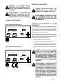
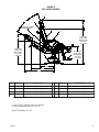
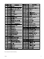
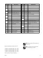
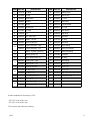
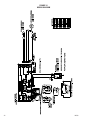
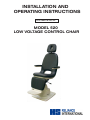
INSTALLATION AND OPERATING INSTRUCTIONS OWNERS MANUAL MODEL 520 LOW VOLTAGE CONTROL CHAIR SERIAL NUMBER For your future reference, mark the serial number in the space provided. QUALITY MANAGEMENT SYSTEM REGISTERED TO ISO 9001:2008 ISO 13485:2003 MADE I N A M E R I C A Reliance® Medical Products • 3535 Kings Mills Road • Mason, Ohio 45040-2303 • 1-800-735-0357 • www.reliance-medical.com TABLE OF CONTENTS IMPORTANT INFORMATION.............................................4 1. INTRODUCTION.........................................................5 TECHNICAL SPECIFICATIONS.........................................6 2. INSTALLATION...........................................................7 2.1. Unpacking.......................................................7 Chair......................................................................7 2.2. Assembly.........................................................7 Headrest......................................................................7 Power Receptacle...................................................7 3. OPERATION..............................................................8 3.1. Chair Lift........................................................8 Raising & Lowering the Chair Lift from the Footswitch...............................................................8 3.2. Chair Top........................................................8 Posistioning the Chair Back.....................................8 3.3. Revolving/Rotation..........................................9 3.4. Armrest Movement..........................................9 3.5. Footrest..........................................................9 3.6. Headrest.........................................................9 4. LOCATING AND REPLACING FUSES............................9 4.1. Fuse Replacement............................................9 TROUBLESHOOTING GUIDE..........................................11 CLEANING AND MAINTENANCE ....................................12 PARTS LIST.................................................................14 Model 520 Chair Assembly....................................15 Chair Top Assembly...............................................16 Chair Base Assembly.............................................18 Lift Assembly.........................................................20 Headrest Assembly................................................22 Wiring Diagram - 520............................................24 LIMITED WARRANTY.....................................................27 IMPORTANT INFORMATION SAFETY SYMBOLS Type B, Applied Part “DANGER”, “WARNING”, or “CAUTION” The exclamation point within an equilateral triangle is intended to alert the user to the presence of important operating and maintenance (servicing) instructions in this Installation and Operating Instructions. Dangerous Voltage / Shock Hazard Fuse Rating Specification « DANGER », « AVERTISSEMENT », ou « PRÉCAUTION » Le point d’exclamation à l’intérieur d’un triangle équilatéral vise à alerter l’utilisateur à la présence d’importantes instructions de fonctionnement et de maintenance (service) dans ce manuel d’installation et d’instructions de fonctionnement. Protective Earth Ground Alternating Current-AC “NOTE” Amplifies a procedure, practice, or condition. Safe Working Load « REMARQUE » Amplifie une procédure, pratique ou condition. ! “Attention, Consult Accompanying Documents” TRANSPORTATION / STORAGE CONDITIONS Temperature: Operating: 59 to 104º F 15 to 40º C Storage: -22 to +140º F -30 to +60º C Relative Humidity: Operating: 5 to 95% without condensation Storage: 10 to 100% including condensation Atmospheric Pressure: Operating: 700hPa - 1060hPa Storage: 500hPa - 1060hPa 4 IN-520 1. INTRODUCTION 1.1. This manual contains information applicable only to the Reliance® Model 520 Chair. 1.2. Whenever you see the symbols shown below, heed their instructions! Always follow safe operating and maintenance practices. “DANGER”- THE DANGER SYMBOL IDENTIFIES SPECIAL INSTRUCTIONS OR PROCEDURES WHICH, IF NOT CORRECTLY FOLLOWED, COULD RESULT IN LOSS OF LIFE OR PERSONAL INJURY. « DANGER » : LE SYMBOLE DANGER IDENTIFIE DES INSTRUCTIONS OU PROCÉDURES SPÉCIALES QUI, SI ELLES NE SONT PAS SUIVIES CORRECTEMENT, POURRAIENT CAUSER UNE PERTE DE VIE OU UNE BLESSURE. “WARNING”- THE WARNING SYMBOL IDENTIFIES SPECIAL INSTRUCTIONS OR PROCEDURES WHICH, IF NOT CORRECTLY FOLLOWED, COULD RESULT IN PERSONAL INJURY. « AVERTISSEMENT » : LE SYMBOLE AV E R T I S S E M E N T I D E N T I F I E D E S INSTRUCTIONS OU PROCÉDURES SPÉCIALES QUI, SI ELLES NE SONT PAS SUIVIES CORRECTEMENT, POURRAIENT CAUSER UNE BLESSURE. “CAUTION”- This caution symbol identifies special instructions or procedures which, if not strictly observed, could result in damage to or destruction of equipment. “NOTE”- Note indicates points of particular or additional information. « REMARQUE » : Remarque indique des points d’intérêt particulier ou des renseignements additionnels. 1.3 Should your product not perform properly, or if you have any questions concerning the use and care of any Reliance® product, contact the Reliance® Distributor, where you purchased this product or contact the Technical Service Department, Reliance® Medical Products, Inc., 3535 Kings Mills Road, Mason, Ohio 45040-2303, or call (800) 735-0358. NOTE: Always have the model number and serial number available before contacting Reliance® or your authorized Reliance® Distributor. REMARQUE : Ayez toujours le numéro de modèle et le numéro de série à portée de la main avant de contacter Reliance® ou votre distributeur Reliance® autorisé. “CLASSIFIED BY CANADIAN STANDARDS ASSOCIATION® WITH RESPECT TO ELECTRIC SHOCK, FIRE AND MECHANICAL HAZARDS ONLY IN ACCORDANCE WITH UL 60601-1.” According to Clause 5 in IEC 60601-1, sec 6.8.1, this unit is classified by the following: • The type of protection against electric shock: EQUIPMENT energized from an external electrical power source: CLASS I EQUIPMENT • The degree of protection against electric shock: TYPE B EQUIPMENT • The degree of protection against harmful ingress of « PRÉCAUTION » : Ce symbole de précaution identifie des instructions ou procédures spéciales qui, si elles ne sont pas strictement suivies, pourraient causer un dommage ou la destruction de l’équipement. water: ORDINARY DEGREE • The degree of safety of application in the presence of a FLAMMABLE ANAESTHETIC MIXTURE WITH AIR or WITH OXYGEN OR NITROUS OXIDE: EQUIPMENT not suitable for use in the presence of a FLAMMABLE ANAESTHETIC MIXTURE WITH AIR or WITH OXYGEN OR NITROUS OXIDE • The mode of operation: CONTINUOUS OPERATION IN-520 5 WARNING: TO PREVENT FIRE OR ELECTRICAL SHOCK HAZARD, DO NOT EXPOSE THIS EQUIPMENT TO RAIN OR MOISTURE. IMPORTANT USER WARNINGS WARNING: EXPLOSION HAZARD. THIS EQUIPMENT MUST NOT BE USED IN THE PRESENCE OF FLAMMABLE ANESTHETICS. AVERTISSEMENT : POUR ÉVITER UN INCENDIE OU UN RISQUE DE CHOC ÉLECTRIQUE, N’EXPOSEZ PAS CET ÉQUIPEMENT À LA PLUIE OU À L’HUMIDITÉ. AVERTISSEMENT : RISQUE D’EXPLOSION. CET ÉQUIPEMENT NE DOIT PAS ÊTRE UTILISÉ EN PRÉSENCE D’ANESTHÉSIQUES INFLAMMABLES. TECHNICAL SPECIFICATIONS Rating for 120V Low Voltage Chair This equipment is rated Class I, Type B Equipment Model Low Voltage Chair 520 Volts Hertz Amps 120V 50/60 5.5 Class I Rating for 230V Low Voltage Chair This equipment is rated Class I, Type B Equipment Model Hertz Amps 230V 50 3.0 6 520 Volts Class I Type B This equipment generates, uses and can radiate radio frequency energy and, if not installed and used in accordance with the instructions, may cause harmful interference to other devices in the vicinity. However, there is no guarantee that interference will not occur in a particular installation. If this equipment does cause harmful interference to other devices, which can be determined by turning the equipment off and on, the user is encouraged to try to correct the interference by one or more of the following measures: Type B Low Voltage Chair POTENTIAL ELECTROMAGNETIC or OTHER INTERFERENCE • Reorient or relocate the receiving device. • Increase the separation between the equipment. • Connect the equipment into an outlet on a circuit different from that to which the other device(s) are connected. • Consult the manufacturer or field service technician for help. WARNING - STORAGE OF THIS EQUIPMENT BELOW 40°F (4.4ºC) WILL CAUSE THE HYDRAULIC OIL TO BECOME THICK. THIS MAY CAUSE UNUSUAL NOISES WHEN THE BASE MOTOR IS OPERATED. IT IS RECOMMENDED THAT THE EQUIPMENT STAY AT A TEMPERATURE OF 60°F (15.6ºC) OR ABOVE FOR AT LEAST 8 HOURS BEFORE OPERATING. AVERTISSEMENT : L’ENTREPOSAGE DE CET ÉQUIPEMENT À MOINS DE 4,4°C (40°F) FERA EN SORTE QUE L’HUILE HYDRAULIQUE DEVIENDRA ÉPAISSE. CECI POURRAIT CAUSER DES BRUITS INHABITUELS LORSQUE LE MOTEUR DE LA BASE FONCTIONNE. ON RECOMMANDE QUE L’ÉQUIPEMENT DEMEURE À UNE TEMPÉRATURE DE 15,6°C (60°F) OU PLUS DURANT AU MOINS 8 HEURES AVANT DE L’UTILISER. IN-520 2. INSTALLATION 2.2.2. Power Receptacle 2.1. Unpacking 2.1.1. Chair 2.1.1.1. Cut the shipping bands, open the top of the shipping carton, and remove all packing material and boxes that can be easily reached. Remove (4) nuts and remove both base clamping boards. 2.1.1.2. It is recommended that the skid be positioned as close as possible to the desired Chair location. 2.1.1.3. Remove at least two small shipping blocks stapled to the top of the skid. The Chair can now be slid and/or tipped from the skid onto the floor. 2.2.2.1. Locate the Footswitch assembly, Chair Control Cable, and the Power Cord Assembly. Refer to figure 1 for receptacle location and attach all cables. Footswitch Cable Power Cord & Fusedrawer Chair Control Cable 2.1.1.4. Do not lift the Chair by the upper structure. However, the Chair may be tipped or slid into position by pushing or pulling on the upper structure. 2.1.1.5. With the Chair in positon, remove all remaining paper pads, plastic, tape, strings, etc. 2.2. Assembly FIGURE 1 BASE 2.2.2.2. To disconnect power to Chair unplug Power Cord from Instrument Stand or from wall receptacle. 2.2.1. Headrest 2.2.1.1. Remove the Headrest from its carton. Remove seat upholstery by pulling the top away from Chair structure. Attach Headrest to Chair frame using two 5/16 x 5/8 hex head cap screws supplied with Chair. Replace seat upholstery. Insert the two locating screws on seat frame into the two holes in bottom of seat upholstery. Press back to frame so the hook and loop fabric fasteners engage. IN-520 7 NOTE: If this Chair is purchased in conjunction with a Reliance® Instrument Stand, the Chair Control Cable supplied will provide proper operation. Refer to the Instrument Stand Manual for connection to the Stand. REMARQUE : Si cette chaise est achetée avec un support à instruments Reliance®, le câble de commande de la chaise fourni permettra un fonctionnement adéquat. Se référer au manuel du support d’instrument pour savoir comment faire la connexion au support. 3. OPERATION CAUTION- Caution should be taken to ensure there are no obstructions (instruments, trays, tables) impeding movement of the Chair PRÉCAUTION : On devrait faire attention pour s’assurer qu’il n’y a pas d’obstructions (instruments, plateaux, tables) empêchant le mouvement de la chaise. Each time main power is applied to the Chair, the circuit board inside the Chair will respond with a one second beep. The beep indicates the electronics are functioning properly. 3.1. Chair Lift 3.1.1. Raising & Lowering the Chair Lift from the Footswitch • For operation from the Footswitch (Figure 2), depress the right side of the pedal to raise the Chair lift. • Depress the left side of the pedal to lower the Chair lift. NOTE: The RAISE and LOWER BASE switches on the Footswitch are programmable. By design, the motion of the Chair will STOP when either of these switches is released. If you want the motion of the Chair to CONTINUE after either of these switches is released, then see Section 4 for programming instructions. LIFT DOWN LIFT UP FIGURE 2 FOOTSWITCH OPERATION 3.2. Chair Top 3.2.1. Positioning The Chair Top •The Chair top may be manually tilted. To do so, release the lock by squeezing the Release Lever and the Grab Bar on the back of the Chair together. Push back to recline. Release two bars to lock top in desired position. (Figure 3). WARNING- FIRM CONTROL OF THE CHAIR TOP MUST BE MAINTAINED DURING THE RECLINING OPERATION. THIS IS ESPECIALLY IMPORTANT WITH HEAVIER OR LIGHTER THAN AVERAGE PATIENTS. “AVERTISSANT” - LE CONTRÔLE FERME DU SOMMET DE PRÉSIDENCE DOIT ÊTRE MIS À JOUR PENDANT L’EXÉCUTION ÉTENDUE. C’EST PARTICULIÈREMENT IMPORTANT AVEC PLUS LOURD OU LE CHALAND QUE LES PATIENTS MOYENS. REMARQUE : Les interrupteurs RAISE (LEVER) et LOWER (BAISSER) la base sur l’interrupteur au pied sont programmables. Selon la conception initiale, le mouvement de la chaise S’ARRÊTE lorsque l’un ou l’autre de ces interrupteurs est relâché. Si vous désirez que le mouvement de la chaise CONTINUE, après que l’un ou l’autre de ces interrupteurs est relâché, consultez la section 4 pour connaître les instructions de programmation. 8 IN-520 PRÉCAUTION : Cette chaise d’examen est conçue pour utilisation dans une position spécifique appelée la position d’utilisation prévue. Avant d’incliner un patient, assurez-vous que le dossier de la chaise est aligné avec le réceptacle d’alimentation de la chaise et que le pivot de la chaise est verrouillé. La charge de travail sécuritaire est réduite si la chaise est tournée hors de sa position d’utilisation prévue et cela pourrait causer une stabilité insuffisante. RELEASE LEVER GRAB BAR FIGURE 3 RELEASE LEVER 3.3. Revolving/Rotation 3.3.1. The Chair upper structure may be revolved 350°, with a built-in stop to prevent continuous rotation. The lock for revolving is controlled by a hand lever with black knob located below the seat at the center and on either side. Push the lever backward to release the lock and pull upward to apply the lock. 3.4. Armrest Movement 3.4.1. The Chair Armrests may be raised to provide better access to the patient or to permit entrance to or exit from the Chair. 3.4.2. The movements of both Armrest are identical and completely independent of each other. 3.4.3. To raise the Armrest simply lift Armrest to the stop parallel to Chair back. CAUTION: This exam Chair is designed for use in a specific position called the Intended Use Position. Prior to reclining a patient, ensure the Chair Back is aligned with the Chair’s power receptacle and that the Chair Swivel is locked. The safe working load is reduced if the Chair is swiveled away from this Intended Use Position, and may result in insufficient stability. IN-520 CAUTION-This exam Chair is designed for use with a specific maximum patient weight as a static (non-moving) load. Sudden weight shifts or impact loads can exceed the safe static load rating of this Chair, and may result in insufficient stability. PRÉCAUTION : Cette chaise d’examen est conçue pour utilisation avec un poids de patient maximum spécifique comme charge statique (sans mouvement). Les déplacements de poids soudains ou les charges dynamiques peuvent excéder la norme de charge statique sécuritaire de la chaise, ce qui pourrait causer une stabilité insuffisante. CAUTION-This exam Chair is designed for use with a patient properly positioned in the Chair. Prior to reclining the Chair, ensure that the patient is seated in the Chair and that the patient position does not move to an extreme position either toward the head of the Chair or toward the foot of the Chair, since this may result in insufficient stability. PRÉCAUTION : Cette chaise d’examen est conçue pour utilisation avec un patient correctement positionné dans la chaise. Avant d’incliner la chaise, assurez-vous que le patient est assis dans la chaise et que la position du patient ne se déplace pas vers une position extrême soit vers la tête, soit vers le pied de la chaise, puisque cela pourrait causer une stabilité insuffisante. 9 4.1. Fuse Replacement (AC Input Module) 3.5. Footrest 3.5.1. The Footrest may be retracted by lifting near its outer edge. When retracted, the Footrest stays in place. 3.6. Headrest 3.6.1. A fixed, non-articulating Headrest is the only Headrest available on the 520 Chair. This Headrest is ergonamically designed for patients of a wide range of heights. 4.1.1 Unplug the power cord from the AC power Input Module. Referring to Figure 4, locate tab. With a tool similar to a small common screwdriver placed under tab, pry Fuse Drawer out. Remove the Fuse Drawer by pulling it out with your fingers. 4.1.2 To remove fuses from Fuse Drawer, tilt fuses in direction of arrows as shown in Figure 4. Examine the fuses, replace as necessary. 4.0 LOCATING AND REPLACING FUSES WARNING: DISCONNECT EQUIPMENT FROM MAIN INPUT POWER BEFORE PROCEEDING WITH ELECTRICAL INSPECTIONS OR MAINTENANCE. FIGURE 4 AC INPUT MODULE AVERTISSEMENT : DÉCONNECTEZ L’ É Q U I P E M E N T D E L’ A L I M E N TAT I O N É L E C T R I Q U E P R I N C I PA L E AV A N T D E PROCÉDER À DES INSPECTIONS ÉLECTRIQUES OU À DE L’ENTRETIEN. CAUTION - Replace fuse(s) as marked. All fuses must be replaced with a fuse of the same size and rating. Refer to the Wire Diagrams at the end of this Manual. PRÉCAUTION : Remplacez le(s) fusible(s) comme indiqué. Tous les fusibles doivent être remplacés par un fusible de la même dimension et de la même valeur. Se référer aux schémas de câblage à la fin de ce manuel. The Chair contain two fuses located inside the AC Input Module in the Base Assembly. 10 IN-520 TROUBLESHOOTING GUIDE PROBLEM PROBLEM CAUSE SOLUTION CHAIR WILL NOT OPERATE. 1) POWER CORD NOT PLUGGED IN. 2) NO AC POWER AT WALL RECEPTACLE. 3) BLOWN LINE FUSE. 1) CHECK ALL WIRING CONNECTIONS. 2) RESTORE OUTLET POWER. 3) REPLACE FUSE. OUTLET POWER OK, BUT NO BEEP IS HEARD WHEN POWER IS APPLIED. 1) BLOWN LINE FUSE. 2) LOOSE WIRING IN BASE. 3) OTHER. 1) REPLACE FUSE. 2) CHECK ALL WIRING CONNECTIONS. 3) CONTACT FACTORY FOOTSWITCH FUNCTIONS NOT OPERATING. 1) FOOTSWITCH CORD NOT CONNECTED. 1) CHECK ALL INTERNAL AND EXTERNAL FOOTSWITCH WIRING CHAIR BASE WILL NOT STAY UP 1) SOLENOID VALVE NOT CLOSED. (DIRT IN VALVE.) 2) CONSTANT POWER APPLIED TO SOLENOID. 3) OTHER 1) REPAIR OR REPLACE SOLENOID VALVE. 2) CHECK FOR SWITCHES STUCK "CLOSED" . 3) CONTACT FACTORY. CHAIR BASE WILL NOT LOWER. 1) NO POWER TO SOLENOID ASS'Y. 2) SOLENOID COIL BURNED-OUT 3) OTHER 1) CHECK FOR VOLTAGE. 2) REPLACE SOLENOID COIL. 3) CONTACT FACTORY. CHAIR BASE WILL NOT RAISE. PUMP MOTOR DOES NOT RUN. 1) 2) 3) 4) 1) 2) 3) 4) CHAIR BASE WILL NOT RAISE. PUMP MOTOR RUNS. 1) SOLENOID VALVE NOT CLOSED. (DIRT IN VALVE.) 2) CONSTANT POWER APPLIED TO SOLENOID. 3) OTHER. 1) REPAIR OR REPLACE SOLENOID VALVE. 2) CHECK FOR SWITCHES STUCK "CLOSED". 3) CONTACT FACTORY. BASE "STUTTERS" DURING ASCENT. 1) HYDRAULIC FLUID LEVEL IS LOW. 1) CONTACT DEALER OR FACTORY FOR INFORMATION ON ADDING OIL. CHAIR BASE WILL NOT RAISE OR LOWER FROM FLOOR UNIT. 1) CHAIR CONTROL CABLE NOT PLUGGED IN. 2) BLOWN FUSE IN CHAIR BASE. 1) CHECK CABLE CONNECTIONS AT STAND CHAIR 2) REPLACE FUSE. CHAIR TOP "WOBBLES" ON CHAIR BASE 1) LOCK NUT IS LOOSE. (UNDER SEAT BOARD.) 1) TIGHTEN LOCK NUT. CHAIR BACK RECLINES FULLY WITHOUT HANDLE BEING ACTIVATED. 1) GAS SPRING IN NEED OF ADJUSTMENT 2) GAS SPRING FAILURE 1) ADJUST GAS SPRING 2) REPLACE GAS SPRING IN-520 NO POWER TO MOTOR PUMP ASS'Y UP-LIMIT SWITCH STUCK "OPEN". PUMP MOTOR BURNED-OUT. OTHER CHECK FOR VOLTAGE. RE-ADJUST OR REPLACE SWITCH. REPLACE MOTOR-PUMP ASS'Y. CONTACT FACTORY. 11 CLEANING AND MAINTENANCE Cleaning the Upholstery When cleaning upholstery, it is suggested that you use all recommended commercial cleaning agents in an inconspicuous spot to check for potential damage to the upholstery material before applying to the entire area to be cleaned. Day to Day soil: Remove ordinary dirt and smudges with a mild soap and warm water solution. Dry with a soft, lint-free cloth or towel. For more difficult stains, use of a stronger detergent is recommended; however, follow the detergent manufacturer’s instructions closely. Disinfecting Material: In order to disinfect, use a 1:9 solution of bleach and water (1 part bleach to 9 parts water). Wipe surface with damp cloth then rinse with water immediately, using a damp cloth. PRÉCAUTION : Ces solvants sont extrêmement inflammables. Faites très attention lors du nettoyage et avisez le personnel dans la zone de tout danger. Portez des gants de caoutchouc durant toute activité de nettoyage. Faites attention en nettoyant autour des boutons, des coutures et autres finitions de bois ou décoratives, puisque ces solvants pourraient endommager sérieusement ces endroits. Cleaning Painted Surfaces The painted metal surfaces are covered in durable, powdercoated paint which is resistant to scratching and scuffing. It may be cleaned with a clean cloth dampened with mild, soapy water or equivalent household product that uses spray application. Special cleaning problems: The following methods are recommended to clean stains on PreFixx-protected vinyl upholstery. Most stains will be removed when these cleaning agents are used in the following order. Type 1 Cleaners: Nonabrasive household cleaners to be used with water and a soft cloth. Recommended Infection Control Products The disinfectant/cleaner products that we have tested and recommend for our upholstery, painted items and plastic covers are as follows. •Formula 409®~ All-Purpose Spray Cleaner •Cavicide® Hospital Disinfectant •Fantastik® Spray Cleaner •Precise® Hospital Foam Cleaner Disinfectant •Other similar household cleaners and bleaches Type 2 Cleaners: Solvent-type cleaner to be liberally applied with a soft cloth. Dry area with another cloth, rinse with clean water and dry. •Rubbing alcohol (isopropyl alcohol) •Lighter fluid (naptha) Type 3 Cleaners: Strong, active solvent cleaners such as nail polish remover (acetone/water) to be applied with a soft cloth. Stain should be removed with less than six (6) rubs; if stain persists after six rubs, contact manufacturer. Dry area with another cloth, rinse with clean water and dry. CAUTION- These solvents are highly CAUTION : Follow manufacturer’s directions for concentration and application of disinfecting cleaner. Avoid prolonged application of any disinfectant/cleaner products, because they may cause staining or discoloration of material. PRÉCAUTION : Suivez les instructions du fabricant pour la concentration et l’application de nettoyeurs désinfectants. Évitez une application prolongée de tout produit désinfectant/nettoyant, parce que ceux-ci pourraient causer des taches ou une décoloration du matériel. flammable. Exercise proper care in cleaning and notify personnel in area of danger. Wear rubber gloves during all cleaning activity. Use caution in cleaning around buttons, stitching and wooden or other decorative trim, since these solvents could seriously damage such areas. 12 IN-520 (NOTES) IN-520 13 PARTS LIST RELIANCE® MODEL 520 EXAMINATION AND TREATMENT CHAIR Note: When ordering parts, please: 1. Advise dealer or factory of model and serial number of unit. These numbers are on the plate that is located at rear, near bottom, of Chair back. 2. Specify color of painted parts. Painted parts have an asterisk(*) behind the part description. REMARQUE : Lorsque vous commandez des pièces, veuillez : 1. Informez le distributeur ou l’usine du modèle et du numéro de série de l’ensemble. Ces numéros sont de la plaque qui est située à l’arrière, près du bas, de l’arriére de présidence. 2. Spécifier la couleur des pièces peintes. Les pièces peintes ont un astérisque (*) derrière la description de pièce. Should your Chair not perform properly, or if replacement parts are needed, contact the Reliance® Distributor, where you purchased this product or contact the Technical Service Department, Reliance® Medical Products, Inc., 3535 Kings Mills Road, Mason, Ohio 45040-2303, or call (800) 735-0358. 14 IN-520 FIGURE 5 520 CHAIR ASSEMBLY 3 40° 1 11.12" MODEL AND SERIAL NUMBER PLATE 5 7, 8 44.00" LOW 46.50" HIGH BASE TRAVEL 8.75" LOW 11.25" HIGH 7.55" 28.88" LOW 31.38" HIGH BASE TRAVEL 8.75" LOW 11.25 HIGH 6 2 4 21.00" LOW 23.50 HIGH BASE TRAVEL 8.75" LOW 11.25 HIGH BASE 19.09" 30.94" 38.96" ITEM PART NO. DESCRIPTION ITEM PART NO. DESCRIPTION 1 Chair Top Assembly* (See Figure 6) 5 2723973 Upholstered Seat Assembly** 2 Chair Base Assembly* (See Figure 7) 6 2346773 Upholstered Apron Assembly** 3 Headrest Assembly* (See Figure 9) 7 2347373 Upholstered Armrest Assembly - RH** Footrest 8 2347473 Upholstered Armrest Assembly - LH** 4 2342203 ** Please specify upholstery color when ordering. To order complete Upholstery Set use P/N. 2349373 Upholstery Set - 520 IN-520 15 FIGURE 6 520 CHAIR TOP ASSEMBLY 24 27 32 17 16 41 (2) 40 (4) 31 15 11 18 42(2) 6 46 (2) 33 (6) 4 38(4) 22 54(2) 10 (4) 15 29 19 45 (2) 44 49 (2) 15 7 43(2) 36(2) 15 5 26 48 30 (2) 47 (2) 15 20 12 52 (2) 3 28 (2) 34(4) 14 25 55 21 37 50 13(2) 23(2) 39 1 53 51(2) 56 9 16 2 8 35(2) IN-520 Z *Please specify paint color when ordering. IN-520 17 FIGURE 7 CHAIR BASE ASSEMBLY 3, 4 9 11 20 10 18 19 7 5 32 8 12 28, 17 6 21 28, 17 13 16, 17 29 30 31, 30 15 23 33 14 30 24 1 27 25 2 22 18 IN-520 ITEM PART NO. Base 16 0458999 Tubing-5-1/2 in 2065599 Base Cover 17 1081999 Tubing Insert 2065199 Base Housing - Low - RH 18 0559999 Thrust Bearing 2065399 Base Housing - High - RH 19 0560099 Thrust Washer 2065299 Base Housing - Low - LH 20 0123885 Lock Nut 2065499 Base Housing - High - LH 21 1127599 Union Tee Lift Assembly (See Figure 8) 22 1659299 Power Cord Assembly 1707792 Solenoid Valve Assembly-120V 23 1550599 Chair Control Cable-LV To LV 1707892 Solenoid Valve Assembly-230V 24 2346492 Footswitch Assembly 1702892 Keyshield Assembly-Low* 1634299 Fuse, 6.3 A / 250V-120V 1702992 Keyshield Assembly-High* 1634999 Fuse, 4 A / 250V-230V 2720092 Pump/Motor Assembly-120V 26 1976799 Power Entry Module W/ Filter 2720192 Pump/Motor Assembly-230V 27 9 1547899 Piston Rod Bolt 28 10 1525899 Set Screw-#10-24 x 1/4 11 0607299 Washer 12 2721092 Hose Assembly 13 1596292 14 15 ITEM PART NO. 1 2081203 2 3 4 5 6 7 8 DESCRIPTION 25 DESCRIPTION Fusedrawer, 2 Pole (In Item 26) 0458999 Tubing-5 in 1597299 Capacitor, Starting-120V 2002199 Capacitor, Starting-230V 30 1720399 PH Phil w/Lock Washer-#10-24 x 1/2 Pressure Tube Assembly 31 2081099 Housing Mount Bracket 2025599 P.C. Board Assembly 32 0708599 HHCS 3/8-16 x 1.5 2720892 AC Input Assembly 33 1569999 Circuit Board Support 29 NOTE- Power cord for 230V base does not include a plug. To order complete Base Assembly use P/N’s. 2724092 2724192 2724292 2724392 NOTE- Le cordon de secteur pour la base 230V ne comprend pas une fiche. Chair Base Assembly - Low - 120V* Chair Base Assembly - High - 120V* Chair Base Assembly - Low - 230V* Chair Base Assembly - High - 230V* *Please specify paint color when ordering. IN-520 19 FIGURE 8 LIFT ASSEMBLY 6 7 21 5 4 3 8 9 10 2 22 23 17 24 25 14 15 13 16 18 12 19 36 35 34 33 & 37 18 43 29 32 27 28 31 30 38 26 20 42 41 11 40 1 20 IN-520 39 DESCRIPTION ITEM PART NO. Lift Base 22 0733299 Retaining Ring 1019095 Lift Top 23 0512599 Backup Ring 3 0439979 Switch Plate 24 0730899 U - Pack 4 0929699 Insulator 25 0512499 Piston Ring 5 1011399 Switch 26 0353199 Cylinder Gasket 6 0727599 Drive Screw 27 0569299 Pin - Roll 7 0731499 "O" Ring 28 0466399 Filter Screen 8 1454699 Pin 29 0446099 Snap Ring 9 0485199 Nut - Acorn 5/16 30 0741799 Valve Ball 10 0365799 Gasket - Tie Rod 31 0731199 "O" Ring 11 0432599 Base Column Seal 32 0441999 Valve Seat 0903292 Cylinder Assembly - High 33 1012499 Valve Housing 0526792 Cylinder Assembly - Low 34 0363299 Relief Valve Plunger 13 Spacer - Cylinder (in Item 12) 35 0784699 Relief Valve Spring 14 Bushing (in Item 12) 36 1012399 Set Screw 15 Ring - Quad (in Item 12) 37 0731299 "O" Ring 0902285 Base Column - High 38 0442499 Valve Spring 0563885 Base Column - Low 39 2720799 Elbow - 45° 0432599 Base Column Seal 40 1081899 Elbow - 90° 0901999 Tie Rod - High 41 0447199 Elbow - 90° 0563699 Tie Rod - Low 42 0303699 Plug - Pipe 1/8-27 Sckt Head Pin - Roll (in Item 12) 43 1060392 Tubing Assembly ITEM PART NO. 1 1012795 2 12 16 17 18 19 20 21 DESCRIPTION 0422899 Disc - Valve 1183592 Piston Rod - High 1183692 Piston Rod - Low To order complete Base Assembly use P/N’s. 2721192 Lift Assembly - Low* 2721292 Lift Assembly - High* *Please specify paint color when ordering. IN-520 21 FIGURE 9 HEADREST ASSEMBLY 1 5 4 3 6 7 2 22 IN-520 ITEM PART NO. DESCRIPTION 1 2059499 Headrest Cover * 2 2057103 Headrest Support Bracket* 3 2059673 Upholstery Headrest ** 4 0713199 R.H.M.S. 1/4-20 x 3/4 5 0728299 1/4 Split Washer 6 2728099 Standoff, Hex Male/Female-#10-32 x 1.50 7 0593799 B.H.C.S #10-32 x .50 Sck't To order complete Headrest Assembly use P/N. 2059592 Headrest Assembly** *Please specify paint color when ordering. ** Please specify upholstery color when ordering. IN-520 23 FIGURE 10 WIRING DIAGRAM 24 IN-520 (NOTES) IN-520 25 (NOTES) 26 IN-520 LIMITED WARRANTY The Reliance® product must be used only for the purposes and in the manner described in the literature distributed with the product. The products are warranted against defective materials and workmanship for the period set forth in the warranty provided with each product. Products or parts thereof will be repaired or replaced as required at Reliance® Medical Products, Inc. Such repair or replacement shall be the sole remedy under this warranty. This warranty extends only to the original purchaser from an authorized Reliance® dealer and is subject to the following conditions: 1. The warranty card must be completed and returned to Reliance® Medical Products, Inc. within two(2) weeks from the date of installation. 2. Installation and servicing of the products must be performed by trained Reliance® equipment dealer service personnel in accordance with the appropriate instructions manual for the products. 3. The products have not sustained breakage or other type damage due to accident or misuse. 4. This warranty will not apply to Reliance® products which have had the serial number removed, altered or effaced. EXCEPT FOR THE EXPRESS WARRANTY SET FORTH ABOVE, RELIANCE® DOES NOT GRANT ANY WARRANTIES, EITHER EXPRESS OR IMPLIED, INCLUDING IMPLIED WARRANTIES OF MERCHANTABILTY OR FITNESS FOR A PARTICULAR USE. Reliance® Medical Products neither assumes nor authorizes any person to assume for it, any other liability in connection with the sale and use of its products. REMEDIES ARE LIMITED EXCLUSIVELY TO REPAIR OR REPLACEMENT OF PARTS. RELIANCE® MEDICAL PRODUCTS, INC. EXPRESSLY DISCLAIMS LIABILITY FOR INCIDENTAL OR CONSEQUENTIAL DAMAGE RESULTING FROM THE USE OF THE EQUIPMENT. Claims covered by this warranty will be honored when presented within one (1) month from discovery of a defect. IN-520 27 MADE IN AMERICA 3535 Kings Mills Road Mason, Ohio 45040-2303 1-800-735-0357(Customer Service) 1-800-735-0358 (Technical Service) (513) 398-3937 Http://www.reliance-medical.com P/N 20607 REV J © Copyright 2007 Printed in U.S.A. Revised 02-2012-7929