1
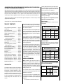
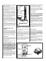
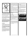
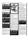
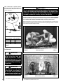
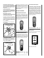
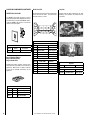
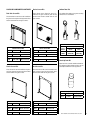
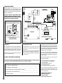
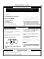
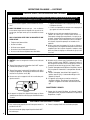
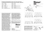
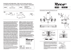
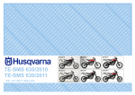
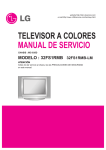
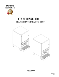
care and operation
instructions
RETAIN THESE INSTRUCTIONS
FOR FUTURE REFERENCE
WARNINGS
• Hot! Do not touch! The glass and
surfaces of this appliance will be hot
during operation and will retain heat
for a while after shutting off the appliance. Severe burns may result.
• Carefully supervise children in the
same room as appliance.
• If small children are present in the home, it is
recommended that this appliance be fitted with
a screen door or screen panel kit. See Page 11
for ordering information.
WARNING: IF THE INFORMATION IN THIS MANUAL
IS NOT FOLLOWED EXACTLY, A FIRE OR EXPLOSION MAY RESULT CAUSING PROPERTY DAMAGE,
PERSONAL INJURY OR LOSS OF LIFE.
FOR YOUR SAFETY: Do not store or use gasoline
or other flammables or liquids in the vicinity of
this or any other appliance.
FOR YOUR SAFETY: What to do if you smell gas:
•DO NOT light any appliance.
•DO NOT touch any electrical switches.
•Do not use any phone in your building.
•Immediately call your gas supplier from a
neighbor’s phone. Follow your gas suppliers
instructions.
•If your gas supplier cannot be reached, call
the fire department.
Installation and service must be performed by
a qualified installer, service agency or the gas
supplier.
US
OTL Report No. 116-F-22-5
DIRECT VENT
MONTEBELLO™
TM
VENTED GAS FIREPLACE - DIRECT VENT MODELS
P/N 875,027M REV. E 08/2007
MODELS
Millivolt Models
LSM40MN-2
LSM40MP-2
LSM45MN-2
LSM45MP-2
Electronic Models
LSM40EN-2
LSM45EN-2
A French manual is available upon request. Order P/N 875,027CF
Ce manuel d’installation est disponible en francais, simplement en
faire la demande. Numéro de la pièce 875,027CF
AVERTISSEMENT: ASSUREZ-VOUS DE BIEN
SUIVRE LES INSTRUCTIONS DONNÉ DANS CETTE
NOTICE POUR RÉDUIRE AU MINIMUM LE RISQUE
D'INCENDIE OU POUR ÉVITER TOUT DOMMAGE
MATÉRIEL, TOUTE BLESSURE OU LA MORT.
POUR VOTRE SÉCURITÉ: Ne pas entreposer ni
utiliser d'essence ni d'autre vapeurs ou liquides
inflammables dans le voisinage de cet appareil ou
de tout autre appareil.
POUR VOTRE SÉCURITÉ: Que faire si vous sentez
une odeur de gaz:
•Ne pas tenter d'allumer d'appareil.
•Ne touchez à aucun interrupteur. Ne pas vous
servir des téléphones se trouvant dans le batiment où vous vous trouvez.
•Evacuez la piéce, le bâtiment ou la zone.
•Appelez immédiatement votre fournisseur de
gaz depuis un voisin. Suivez les instructions
du fournisseur.
•Si vous ne pouvez rejoindre le fournisseur de
gaz, appelez le service dos incendies.
L'installation et service doit être exécuté par un
qualifié installeur, agence de service ou le fournisseur de gaz.
SAFETY & WARNING
INFORMATION
Important: Please read THIS
MANUAL IN ITS ENTIRETY and
understand these Rules to
follow for safety.
WARNING
If the information in this
manual is not followed
exactly, a fire or explosion may result causing property damage,
personal injury or loss
of life.
WARNING
Improper installation, adjustment, alteration, service or
maintenance can cause injury
or property damage. Refer to
this manual. For assistance or
additional information consult
a qualified installer, service
agency or the gas supplier.
WARNING
Failure to comply with the installation and operating instructions
provided in this document will
result in an improperly installed
and operating appliance, voiding
its warranty. Any change to this
appliance and/or its operating
controls is dangerous. Improper
installation or use of this appliance can cause serious injury or
death from fire, burns, explosion
or carbon monoxide poisoning.
IMPORTANT
These appliances must not be
connected to a chimney or flue
serving a separate solid-fuel
burning appliance.
WARNING
Do not place clothing or other
flammable materials on or near
this appliance.
AVERTISSEMENT
Surveiller les enfants. Garder les
vêtements, les meubles, l'essence
ou autres liquides à vapeur inflammables à cote de l'appareil.
WARNING
Children and adults should be
alerted to the hazards of high
surface temperatures. Use
caution around the appliance
to avoid burns or clothing ignition. Young children should be
carefully supervised when they
are in the same room as the
appliance. Note: An Optional
Screen Panel for the glass is
available (see Page 11 for ordering information).
WARNING
Carbon Monoxide Poisoning:
Early signs of carbon monoxide
poisoning are similar to the flu
with headaches, dizziness and/or
nausea. If you have these signs,
obtain fresh air immediately. Turn
off the gas supply to the appliance
and have it serviced by a qualified
professional, as it may not be operating correctly. Some people are
more affected by carbon monoxide
than others. These include pregnant women, people with heart
or lung disease or anemia, those
under the influence of alcohol, and
those at high altitudes.
WARNING
Any safety guard or screen
removed for servicing the appliance must be replaced prior to
operating the appliance.
WARNING
Do not attempt to alter or modify
the construction of the appliance
or its components. Any modification or alteration may void
the warranty, certification and
listings of this unit.
WARNING
Do not use these appliances if
any part has been under water.
Immediately call a qualified,
professional service technician
to inspect the appliances and to
replace any parts of the control
system and any gas controls
which have been under water.
AVERTISSEMENT
Ne pas se servir de cet appareil
s'il a été plongé dans l'eau,
complètement ou en partie.
Appeler un technicien qualifié
pour inspecter l'appareil et remplacer toute partie du système de
contrôle et toute commande qui
ont été plongés dans l'eau.
IMPORTANT
The vent termination is hot while
in operation and for a period of
time following the use of the
fireplace. Young children should
be carefully supervised when
they are in the same area as at
hot termination.
WARNING
This appliance is only for use with
the type of gas indicated on rating
plate. This appliance is not convertible for use with other gases,
unless a certified kit is used.
AVERTISSEMENT
Cet appareil doit être utilisé
uniquement avec les types de
gaz indiqués sur la plaque signalétique. Ne pas l'utiliser avec
d'autres gaz sauf si un kit de
conversion certifié est installé.
WARNING
These fireplaces are vented
gas appliances. Do not burn
wood or other material in these
appliances.
CONGRATULATIONS ON THE PURCHASE OF YOUR NEW GAS APPLIANCE MANUFACTURED BY LENNOX HEARTH PRODUCTS.
When you purchased your new gas-fired fireplace, you joined the ranks of thousands of individuals
whose answer to their home heating needs reflects their concern for efficiency and our environment.
We extend our continued support to help you achieve the maximum benefit and enjoyment available
from your new gas-fired fireplace. It is our goal at Lennox Hearth Products to provide you, our
valued customer, with an appliance that will ensure years of trouble-free warmth and pleasure.
Provide adequate clearances around air openings and adequate accessibility clearance for
service and proper operation. Never obstruct
the front openings of the appliance.
Due to high temperatures the appliance should
be located out of traffic and away from furniture
and draperies. Locate furniture and window
coverings accordingly.
Thank you for selecting a Lennox Hearth Products gas-fired fireplace as the answer to your home
supplemental heating needs.
These appliances are designed to operate on
natural gas or propane gas only.
Sincerely, All of us at Lennox Hearth Products
Millivolt Models Input of millivolt models is shown in the following table:
TABLE OF CONTENTS
Safety and Warning Information.........Page 2
Introduction........................................Page 3
General Information............................Page 3
Operation/Care of Your Appliance.......Page 4
Variable Flame Adjustment..................Page 5
Maintenance........................................Page 5
Maintenance Schedule........................Page 6
Front Glass Enclosure Panel,
Removal and Installation..................Page 7
Burner Adjustments............................Page 7
Flame Appearance and Sooting...........Page 7
Adjustment..........................................Page 7
Logs, Glowing Embers, Volcanic
Stone Placement..............................Page 8
Millivolt Appliance Checkout...............Page 9
Electronic Appliance Checkout............Page 9
Accessory Components......................Page 9
Wiring Diagrams.................................Page12
Warranty.............................................Page12
Replacement Parts..............................Page12
Product Reference Information...........Page12
Lighting Instructions – Millivolt..........Page13
Lighting Instructions – Electronic.......Page15
Troubleshooting Guide – Millivolt.......Page17
Troubleshooting Guide – Electronic....Page18
Replacement Parts List.......................Page19
Introduction
The fireplace models covered in this manual are
Direct-Vent, sealed combustion gas fireplaces
designed for residential application. DirectVent appliances operate with the combustion
chamber completely isolated from the inside
atmosphere. All air for combustion is brought
in from the outside and exhaust gases are
vented through the same direct vent, vent
system.
The millivolt appliances are designed to operate
on either natural or propane gas. A millivolt gas
control valve with piezo ignition system provides
safe, efficient operation.
The electronic appliances are designed to operate on natural gas only. An electronic intermittent
pilot system provides safe, efficient operation.
External electrical power is required to operate
these units.
These appliances comply with National Safety
Standards and are tested and listed by OMNITest Laboratories (Report No. 116-F-22-5) to
ANSI Z21.50 (in Canada, CSA-2.22), and CAN/
CGA-2.17-M91 in both the USA and Canada as
vented gas fireplaces.
The Installation must conform to local codes or,
in the absence of local codes, with the National
Fuel Gas Code, ANSI Z223.1/NFPA 54 - latest
edition, or the Natural Gas and Propane Installation Code, CSA B149.1 - latest edition. The
appliance, when installed, must be electrically
grounded in accordance with local codes or, in
the absence of local codes, with the National
Electrical Code, ANSI/NFPA 70 - latest edition,
or the Canadian Electrical Code, CSA C22.1
- latest edition.
General Information
Note: Installation and repair should be performed by a qualified service person. The
appliance should be inspected annually by a
qualified professional service technician. More
frequent inspections and cleanings may be
required due to excessive lint from carpeting,
bedding material, etc.
It is imperative that the control compartment,
burners and circulating air passage ways of the
appliance be kept clean.
S'assurer que le brùleur et le compartiment des
commandes sont propres. Voir les instructions
d'installation et d'utilisation qui accompagnent
l'appareil.
NOTE: DIAGRAMS & ILLUSTRATIONS ARE NOT TO SCALE.
Millivolt Models with
Manually-Modulated Gas Valve
Natural Gas
Propane Gas
Model
No.
Input
(BTU/Hr)
Model
No.
Input
(BTU/Hr)
LSM40-2
40,000 to
50,000
LSM40-2
40,000 to
50,000
LSM45-2
47,000 to
60,000
LSM45-2
48,000 to
60,000
Table 1
Electronic Models Electronic models have a manually-modulated
gas valve. Input of electronic models is shown
in the following table:
Electronic Models with
Manually-Modulated Gas Valve
Natural Gas
Propane Gas
Model
No.
Input
(BTU/Hr)
Model
No.
Input
(BTU/Hr)
LSM40-2
40,000 to
50,000
LSM40-2
40,000 to
50,000
LSM45-2
47,000 to
60,000
LSM45-2
48,000 to
60,000
Table 2
Table 3 shows the gas orifice size required
for the elevations indicated.
Model
Orifice Size
Nat.
Prop.
LSM40-2
.1405"
(#28)
.086"
(#44)
LSM45-2
.161"
(#20)
.093"
(#42)
Elevation
Feet (meters)
0-4500
(0-1372)
Table 3
Maximum manifold pressure is 3.5 in. W.C.
(0.87 kPa) for natural gas and 10 in. W.C. (2.49
kPa) for LP/Propane gas.
Test gauge connections are provided on the
front of the millivolt and electronic gas control
valve (identified OUT for the manifold side and
IN for inlet pressure).
Minimum inlet gas pressure to these appliances
is 5.5 inches water column (1.37 kPa) for natural
gas and 11 inches water column (2.74 kPa) for
propane for the purpose of input adjustment.
Maximum inlet gas supply pressure to these
appliances is 10.5 inches water column (2.61
kPa) for natural gas and 13.0 inches water
column (3.23 kPa) for propane.
Refer to Figure 1 for access to the gas control
valve. Millivolt appliances will be fitted with the
gas control valve shown in Figure 2.
Right Side
Modesty Panel
Appliances with electronic systems will be fitted
with the electronic valve shown in Figure 3.
Familiarize yourself with the gas control valve
that your appliance uses.
Access Plate
Hi-Lo
Extension Knob
Millivolt Appliances To light millivolt appliances refer to the detailed
lighting instructions found on Page 12 . Millivolt
appliance lighting instructions may also be
found on the pull out lighting instruction labels
attached to the gas control valve.
Gas Valve
ON/OFF Switch
The appliance must be isolated from the gas
supply piping system (by closing its individual
manual shut-off valve) during any pressure
testing of the gas supply piping system at
test pressures equal to or less than 1/2 psig
(3.5 kPa).
The appliance and its individual shut-off valve
must be disconnected from the gas supply
piping system during any pressure testing of
that system at pressures in excess of 1/2 psig
(3.5 kPa).
Operation and care of your
appliance
Appliance operation may be controlled by the
following means: the factory provided ON/OFF
control switch, a remotely located optional wall
switch or optional remote control. The mounted
ON/OFF control switch is located on the right
hand side of the appliance. See Figure 1.
Burn-in Period
During the first few fires of this appliance there
will be some odor due to the curing of the
paint and burning off of lubricants used in the
manufacturing process.
Piezo
Igniter
Control Compartment Access Millivolt Control Valve Shown
Figure 1
Gas Controls / Control Compartment
Access
The gas controls can be found on the right hand
side of the appliance.
On millivolt systems, the piezo igniter, Hi/Lo
flame adjustment knob, and pilot and main gas
ON/OFF control knob are located on the right
side. On both millivolt and electronic systems
the gas valve is located on the right side of the
appliance. See Figure 1.
Operation of millivolt and electronic gas control systems are different. Before lighting and
operating your appliance determine if you have
a millivolt or electronic appliance.
Depending on your use, the burn-in period may
take a few hours or a few days.
OFF
Electronic appliances are fitted with an ON/OFF
rocker switch for appliance ON/OFF control. See
Figure 1 for its location.
Once the pilot is lighted, the ON/OFF rocker
switch will control the appliance ON/OFF operation. To operate: Toggle the switch between its
ON and OFF positions.
LO W
HI
P IL
OT
To light electronic appliances refer to the detailed
lighting instructions found on Page 15 of these
instructions respectively. Electronic appliance
lighting instructions may also be found on the
pull out lighting instruction labels attached to
the gas control valve.
Manifold
Pressure Port
Variable Flame
Height Adjustment
Pilot Adjustment
Screw
TPTH
TP
TH
Figure 2 - SIT Millivolt Gas Valve
NOTE: DIAGRAMS & ILLUSTRATIONS ARE NOT TO SCALE.
Electronic Appliances -
ON
ti
If your millivolt appliance is equipped with an
optional remote wall switch or remote control
kit and the pilot is lit, the appliance main burner
may be turned on and off with the wall switch
or remote control.
Main Gas
Control Knob
P IL O T
OUT
A white film may develop on the glass front
during the first few fires as part of the curing
process. The glass should be kept clean during
the first two weeks of use to prevent the film from
baking on (making it very difficult to remove).
See Glass Cleaning on Page 5.
Inlet Pressure
Port
IN
KEEP YOUR HOUSE WELL VENTILATED
DURING THE CURING PROCESS. THE ODOR
AND HAZE EMITTED DURING THE CURING
PROCESS CAN BE QUITE NOTICEABLE AND
MAY SET OFF A SMOKE DETECTOR. ENSURE
THAT A SMOKE DETECTOR IS NOT LOCATED
DIRECTLY ABOVE THE APPLIANCE OR TOO
CLOSE TO THIS APPLIANCE (FOLLOW SMOKE
DETECTOR MANUFACTURER'S INSTRUCTIONS FOR PROPER LOCATION).
Millivolt appliances are fitted with an ON/OFF
Rocker Switch for appliance ON/OFF control.
See Figure 1 for its location. Once the pilot is
lighted, the ON/OFF rocker switch will control
the appliance ON/OFF operation. To operate:
Toggle the switch between its ON and OFF
positions.
Inlet Pressure
Gauge Port
Always keep the appliance area clear and free
from combustible materials, gasoline and other
flammable liquids.
Remember, Millivolt appliances have a continuous burning pilot flame. Exercise caution when
using products with combustible vapors.
LO
HI
Hi-Lo Flame
Adjustment
Knob
Always turn off gas to the pilot (millivolt appliances) before cleaning. Before re-lighting,
refer to the lighting instructions in this manual.
Instructions are also found on pull-out lighting
instruction labels attached to the gas valve.
Manifold
Pressure
Gauge Port
Pilot
Adjustment
Screw
Figure 3 - SIT Electronic Gas Valve
If your electronic appliance is equipped with an
optional remote wall switch or remote control kit
the appliance main burner may be turned on and
off with the wall switch or remote control.
Variable Flame Height Adjustment
All appliances are equipped with a variable gas
control valve. Flame height for these models
may be adjusted through a range between
fixed low and high settings, alternately, while
the appliance is in operation.
Use the extension knob (refer to Figure 1), to
adjust the flame height as desired by sliding
the knob over the variable flame adjustment
knob located on the front of the valve (refer to
Figure 2). Replace the extension knob back
to the hanger after the adjustment.
MAINTENANCE
Refer to the maintenance schedule for maintenance tasks, procedures, periodicity and
by whom they should be performed. Always
verify proper operation of the appliance after
servicing.
Important: Turn off gas and any
electrical power before servicing
the appliance.
Glass Cleaning
(see Front Glass Enclosure Panel, Removal and
Installation on Page 7)
Note: Clean glass after first two weeks of operation (after Burn-In period is over) and then only
when necessary and when the fireplace is cool.
Wipe surface with clean, dampened, soft cloth.
Follow with dry, soft towel as desired. Take care
not to scratch the glass surface.
The viewing glass should be cleaned periodically to remove any build-up caused from the
following:
• Initial curing of the high temperature paint
and burning off of lubricants used in the
manufacturing process may result in a film
on the glass.
• A white coating may form on the glass as a
result of impurities and minerals in the fuel.
It is recommended that the glass be cleaned
two or three times during each heating season,
depending on the circumstances present. The
following cleaning solutions are approved for use
to clean glass:
• Non-ammonia based household cleaner
• 50%-50% mix of white vinegar & water
• Gas fireplace/stove glass cleaner
Inspect Glass Gasket - Visually inspect the
gasket on the backside of the glass enclosure
panels. The gasket surface must be clean, free
of irregularities and seated firmly.
WARNING
Do not use abrasive cleaners.
Never clean the glass when it
is hot.
CAUTION
Do not attempt to touch the front
enclosure glass with your hands
while the fireplace is in use.
• During start-up, it is normal for condensation to form on the inside of the glass (this
condensation and fog will usually disappear
in a few minutes). The moisture can cause
lint, dust and other airborne particles to cling
to the glass surface.
The appliance and venting system should be
thoroughly inspected before initial use and at
least annually by a qualified service technician.
However, more frequent periodic inspections
and cleaning should be performed by the homeowner. Homeowner must contact a qualified
service technician at once if any abnormal
condition is observed.
Keep side control compartment clean by
vacuuming or brushing at least twice a year.
More frequent cleaning may be required due to
excessive lint from carpeting, bedding materials,
etc. It is important that control compartments,
burners and circulating air passageways of the
appliance be kept clean.
NOTE: DIAGRAMS & ILLUSTRATIONS ARE NOT TO SCALE.
MAINTENANCE SCHEDULE
Annually (Before the onset of the Burning Season)
MAINTENANCE TASK
ACCOMPLISHING PERSON
PROCEDURE
Inspecting/Cleaning Burner, Logs
and Controls
Qualified Service Technician
Inspect valve and ensure it is properly operating. Check piping for leaks.
Vacuum the control compartment, fireplace logs and burner area.
Check Flame Patterns and Flame
Height
Qualified Service Technician
Refer to Figure 6 (LSM40-2) or Figure 7 (LSM45-2) on Page 8 and
verify the flame pattern and height displayed by the appliance conforms
to the picture. Flames must not impinge on the logs. Ensure flames
are steady (not lifting or floating).
Inspecting/Cleaning Pilot and Burner
Qualified Service Technician
Refer to Figure 8 (Millivolt) or Figure 9 (Electronic) on Page 9. Remove
any surface build-up on pilot and burner assembly. Wipe the pilot
nozzles, igniter/flame rod and hood. Ensure the pilot flame engulfs the
flame sensor as shown.
Checking Vent System
Qualified Service Technician
Inspect the vent system at the top and at the base (within the firebox)
for signs of blockage or obstruction. Look for any signs of dislocation
or deterioration of the vent components. Note: Excessive condensation
can cause corrosion of caps, pipe & fittings (excessive condensation can
be caused by long lateral runs, too many elbows and/or exterior portions
of the system being exposed to cold weather). Also inspect wall straps
or plumbers's tape to ensure it is secure and in place.
Appliance Checkout
Qualified Service Technician
Perform the appropriate appliance checkout procedure detailed in this
manual.
Replacing Rockwool Ember Materials
Homeowner/Qualified Service
Technician
Remove old ember materials (rockwool) and vacuum the ember placement area. Place new embers as described in the Ceramic Panel And
Log Placement Guide accompanying this document and as shown in
Figures 6 and 7.
ACCOMPLISHING PERSON
PROCEDURE
Periodically (After the Burning Season)
MAINTENANCE TASK
Cleaning Firebox Interior
Homeowner
Carefully remove logs, rockwool, volcanic stone and vermiculite. Vacuum
out interior of the firebox. Clean firebox walls and log grate. Replace logs,
rockwool, vermiculite and volcanic stone as detailed in this manual.
Check Flame Patterns and Flame
Height
Homeowner
Refer to Refer to Figure 6 (LSM40-2) or Figure 7 (LSM45-2) on Page
8 and verify the flame pattern and height displayed by the appliance
conforms to the picture. Flames must not impinge on the logs.
Checking Vent System
Homeowner
Inspect the vent system at the top and at the base (within the firebox)
for signs of blockage or obstruction. Look for any signs of dislocation
of the vent components.
Cleaning Front Glass Enclosure Panel
Homeowner
Clean as necessary following the directions provided in this manual. Do
not touch or attempt to clean glass while hot.
Front Glass Enclosure Panel, Removal
and Installation
top Flange Glass door
Frame assembly
Burner Adjustments
Glass door Latch (2)
WARNING
Do not operate appliance with the
glass front removed, cracked or
broken. Replacement of the glass
should be done by a licensed or
qualified service technician.
These are direct-vent appliances. They are
designed to operate only when the front glass
enclosure panel is installed. Generally the front
glass enclosure panel should not be removed
except to gain access to the components within
the firebox.
WARNING
Handle this glass with extreme
care! Glass is susceptible to
damage – Do not scratch or
handle roughly while reinstalling
the glass door frame.
WARNING
Do not attempt to substitute the
materials used on this door, or
replace cracked or broken glass
with any materials other than
those provided by the appliance
manufacturer.
WARNING
The glass door of this appliance must only be replaced as
a complete unit as provided by
the manufacturer. Do not attempt
to replace broken, cracked or
chipped glass separately.
Refer to Figure 4 and remove the front glass
door assembly as follows:
To remove the firescreens, lift up the center of
the rod to disengage it from the center bracket,
bend down at center, hold left side with hand
until it disengages from left side, being careful
not to scratch paint. Slowly remove the rod
from the right side.
Remove the door modesty shield from the top
flange glass door by pulling it up firmly with both
hands until it is disengaged. Using a phillips
screwdriver, unfasten two (2) screws located
at the top of the glass frame.
The following paragraphs address burner
adjustment concerns and procedures.
When lit for the first time, this appliance will emit
a slight odor for an hour or two. This is due to
the “burn-in” of internal paints and lubricants
used in the manufacturing process.
Flame Appearance and Sooting
(see Figures 6 and 7 on Page 8)
Appliances operated with air shutter openings
that are too large will exhibit flames that are blue
and transparent. These weak, blue and transparent flames are termed anemic. If the air shutter
opening is too small sooting may develop.
screws
Firebox Floor
Glass door assembly
Figure 4
Tilt the glass frame at the top away from the
unit. Lift it carefully off the bottom door track
and set the door aside, protecting it from
inadvertent damage.
To install the front glass door assembly,
proceed as follows:
1.Retrieve the glass door assembly. Visually
inspect the gasket on the backside of the
panel. The gasket surface must be clean,
free of irregularities and seated firmly.
2.Position the door frame in front of the firebox
opening and engage the bottom flange over
the rail at the bottom of the firebox opening.
3.Swing the door up and back. Ensure the
gasket seats evenly as the door draws shut.
Engage the nut insert and fasten with two
screws to secure the door.
4.Install the door modesty shield on top flange
glass door as follows: grab the door modesty
shield with both hands, with the open hem
going down and engage it with the upper lip
of the glass door frame by pushing it all the
way down. Make sure the installed shield is
firmly in place.
5.With the firescreen hanging on the screen
rod, drop in the right side of the rod to the
right modesty panel. Then drop in the left
side of the rod through the slot of the left
modesty panel. Make sure that the rod is
supported by the bracket in the center of the
fireplace.
WARNING
When reinstalling the glass door,
the door latch screws must be
securely tightened to prevent
the glass door from falling out,
which could potentially cause
damage and possible injury.
NOTE: DIAGRAMS & ILLUSTRATIONS ARE NOT TO SCALE.
Sooting is indicated by black puffs developing
at the tips of very long orange flames. Sooting
results in black deposits forming on the logs,
appliance inside surfaces and on exterior surfaces adjacent to the vent termination.
Sooting is caused by incomplete combustion in
the flames and a lack of combustion air entering the air shutter opening. To achieve a warm
yellow to orange flame with an orange body
that does not soot, the shutter opening must
be adjusted between these two extremes. No
smoke or soot should be present. Reposition the
logs if the flames impinge on any of them.
If the logs are properly positioned and sooting
conditions exist, the air shutter opening on the
main burner tube should be adjusted. Normally,
the more offsets in the vent system, the greater the
need for the air shutter to be opened further.
WARNING
Air shutter adjustment should
only be performed by a qualified
professional service technician.
Ensure that the front glass door
assembly is in place and sealed After
adjustment.
Adjustment
To adjust the flame, move the adjustment air
shutter (located on the lower venturi) back or
forward to increase or reduce the air shutter
opening, respectively. Position the air shutter
to the factory setting as shown in Figure 5 on
Page 8. Allow the burner to operate for at least
15 minutes. Observe the flame continuously. If it
appears weak or sooty as previously described,
adjust the air shutter until the flame appearance
is as desired.
Propane models may exhibit a flame pattern
that may candle or appear stringy. If this is
problematic or persists as the appliance is
continually operated, adjust the air shutter
closed as described in the previous paragraphs.
Operate the appliance for a period of time as the
effect diminishes, ensuring that the appliance
does not develop sooty flames.
When satisfied that the appliance operates
properly, proceed to finish the installation. Leave
the control knob in “ON” position and turn the
remote switch “OFF.”
air shutter
opening
WARNING
The size and position of the log set was engineered to give your appliance a safe, reliable and attractive flame pattern. Any attempt to use
a different in the fireplace will void the Warranty and will result in
incomplete combustion, sooting, and poor flame quality.
Carefully position the ceramic fiber logs and twigs over the burner as shown in Figure 6 (LSM40-2)
or Figure 7 (LSM45-2) on this Page. Refer to the detailed log placement instructions provided
in the CERAMIC PANEL AND LOG PLACEMENT GUIDE accompanying this document.
Venturi
orifice
Proper twig placement is critical to prevent sooting. Twigs should be placed in the gaps between
the flame peaks and should be positioned so that at no time they impinge the flames. Placement
is the same for all colors and styles of logs.
Gas
Valve
Burner
Venturi
Main Burner Factory Air Shutter
Opening Setting - Inches (millimeter)
Model
Nat.Gas
Propane Gas
LSM40-2
1/16 (1.59)
9/32 (7.14)
LSM45-2
1/16 (1.59)
9/32 (7.14)
Figure 5
Log Placement
Figure 6
(Birch Logs Shown)
LSM40-2
Figure 7
(Rustic Oak Logs Shown)
LSM45-2
WARNING
Logs get very hot and will remain
hot up to one hour after gas
supply is turned off. Handle
only when logs are cool. Turn
off all electricity to the appliance
before you install grate and logs,
If applicable.
WARNING
This appliance is not meant
to burn wood. Any attempt to
do so could cause irreparable
damage to your appliance and
prove hazardous to your safety.
NOTE: DIAGRAMS & ILLUSTRATIONS ARE NOT TO SCALE.
NOTE: DIAGRAMS & ILLUSTRATIONS ARE NOT TO SCALE.
Glowing Embers (Rockwool) Placement
Refer to the detailed glowing embers placement
instructions provided in the Ceramic Panel
And Log Placement Guide accompanying
this document.
Ceramic Panel Placement
Refer to the detailed ceramic panel placement
instructions provided in the Ceramic Panel
And LOG PLACEMENT GUIDE accompanying
this document.
Millivolt Appliance Checkout
The pilot flame should be steady, not lifting
or floating. Flame should be blue in color with
traces of orange at the outer edge.
The top 3/8" (10 mm) at the pilot generator
(thermopile) and the top 1/8" minimum (tip)
of the quick drop out thermocouple should be
engulfed in the pilot flame. The flame should
project 1" (25 mm) beyond the hood at all three
ports. See Figure 8.
With proper care and maintenance, your appliance will provide many years of enjoyment. If
you should experience any problem, first refer
to the trouble shooting guide in this manual. If
problem persists, contact your Lennox Hearth
Products distributor.
Accessory Components
Standard Remote Control System
The Model RCL (Standard) Remote Control
System, features a simple On/Off control function for the fireplace. This model includes a
hand-held transmitter, a remote receiver with
wall-mount coverplate and all hardware required
to install the unit. The remote receiver can be
wall or hearth mounted.
Deluxe Remote Control System
The Model RCL-T (Deluxe) Remote Control
System has all of the features of the standard
system along with an added easy to read LCD
screen which presents access to many enhancements, including; battery power level indicator,
timer, mode of operation, thermostatic display
including room temperature in either metric
of English units, flame indicator and clock.
Fully programmable, the Model RCL-T allows
for command over nearly all operational and
temperature variables, using the hand held
remote control transmitter.
To light the burner, refer to the lighting instructions on Page 13.
SIT MILLIVOLT PILOT ASSEMBLY
Proper Pilot Flame Appearance
Pilot Hood
Igniter Rod
Remote Control System (Deluxe)
Thermocouple
3/8" Min.
(9 mm)
Remote Control System (Standard)
H0249RCL
Flame Modulating Remote Control
Pilot
Nozzels
Figure 8
Thermopile
Electronic Appliance Checkout
To light the burner, refer to the lighting instructions on Page 15. Ensure the igniter lights the
pilot. The pilot flame should engulf the flame
sensor as shown in Figure 9.
Flame Modulating Remote Controls were developed to provide a safe, reliable and user-friendly
remote control system for appliances equipped
with a Millivolt Gas Valve. A detailed set of
instructions are included with each remote.
H0251RCL-T
Wall Thermostat
The wall thermostat kit provides temperature
control for optimum comfort.
ELECTRONIC PILOT ASSEMBLY
Proper Pilot Flame Appearance
Pilot Hood
Igniter
Rod
Flame
Sensor
Pilot
Nozzels
Figure 9
89L36 WTK Wall Thermostat Kit
Flame Modulating Remote Control
– Natural Gas
Flame Modulating Remote Control
– LP/Propane Gas
H0301RCL-MN
H0302RCL-ML
NOTE: DIAGRAMS & ILLUSTRATIONS ARE NOT TO SCALE.
Accessory Components Continued
ON/OFF Wall Switch Kit
The ON/OFF wall switch kit may be used to
control the operation of the fireplace burner as an
alternative to the unit mounted ON/OFF switch.
Install the ON/OFF wall switch in a convenient
location near the fireplace.
Brick Liner Kits
Log Sets
The brick panel liner kits include ceramic panels
of the side and rear walls. The panels have
brick-like features in relief.
Choose from two finely crafted log sets with
detailing that replicates the natural look of
real wood.
Birch Logs
Brick Liner Kits
LSM40-2
ON/OFF Wall Switch Kit
Cat. No.
Model
Description
85L87
FWSK
Wall Switch
Bag of Glowing Embers
Bag of Volcanic Stone
Bag of Vermiculite
H2219
BLKR-LSM40
Buff Rustic
H4801
BLK-REDR-LSM40
Red Rustic
H2220
BLKH-LSM40
Buff Herringbone
H4803
BLK-REDH-LSM40
Red Herringbone
H2221
BLKC-LSM40
Red Old Cottage
H2222
BLKB-LSM40
Black
Replacement ember material, volcanic stone
and vermiculite are available for use with these
appliances. Order them to replace materials
as part of the periodic maintenance of the
appliance.
H2223
BLKR-LSM45
Buff Rustic
H2224
BLKH-LSM45
Buff Herringbone
H2225
BLKC-LSM45
Red Old Cottage
Black
Model
88L53
FGE
Bag of Glowing Embers
80L42
FDVS
Bag of Volcanic Stone
10
Log Sets
Cat. No.
Model
Description
LSM40-2 and LSM45-2
H2226
BLKB-LSM45
H4802
BLK-REDR-LSM45
Red Rustic
H4799
LOG-OAK-LSM-2
Oak Log Set
H4804
BLK-REDH-LSM45
Red Herringbone
H4800
LOG-BIR-LSM-2
Birch Log Set
Firebox Accessories
Cat. No.
H3696
Rustic Oak
LSM45-2
Description
Bag of Vermiculite
NOTE: DIAGRAMS & ILLUSTRATIONS ARE NOT TO SCALE.
Accessory Components Continued
Barrier Screen Kits
Andiron Door Kits
Dual Arch Screen Kits
These Barrier Screen Panel kits can be installed on the glass enclosure panel to help
prevent direct human contact with the hot
glass surface.
The andiron kits attach to the grate assembly
without the use of hardware.
These Dual Arch screen kits can be installed on
the glass enclosure panel to help prevent direct
human contact with the hot glass surface.
CLASSIC
MISSION
Andiron Door Kits
Dual Arch Screen Kits
Cat. No.
Model
Description
Barrier Screen Kits
Cat. No.
LSM40-2
H5051
Description
LSM40-2
DASK-LSM40-2 Dual Arch Screen
H4805
LSM45-2
H5054
Model
BSK40
Fits
Fireplace
Models
Catalog No. (Model)
Mission
Classic
LSM40-2 &
LSM45-2
H2227
(AKM-LSM)
H2228
(AKC-LSM)
Barrier Screen
LSM45-2
DASK-LSM45-2 Dual Arch Screen
H4806
BSK45
Barrier Screen
Touch-Up Paint Kit
Repair of minor scratches and discoloration of
the appliances black painted surfaces may be
accomplished with the touch-up paint kit.
Classic Screen Kits
Arch Screen Kits
These Screen kits can be installed on the glass
enclosure panel to help prevent direct human
contact with the hot glass surface.
These Arch Screen kits can be installed on the
glass enclosure panel to help prevent direct
human contact with the hot glass surface.
PA I N T
Touch-Up Paint (Black) Kit
Model
Description
Cat. No.
SK-LSM40-2
Classic Screen Kit
H5053
SK-LSM45-2
Classic Screen Kit
90L73
FTPK-B
Black Paint Kit
Model
Description
ASK-LSM40-2
Arch Screen Kit
LSM45-2
LSM45-2
H5055
Description
LSM40-2
LSM40-2
H5052
Model
Arch Screen Kits
Classic Screen Kits
Cat. No.
Cat. No.
H5056
ASK-LSM45-2
Arch Screen Kit
NOTE: DIAGRAMS & ILLUSTRATIONS ARE NOT TO SCALE.
11
Wiring Diagrams
piLot Burner
iGniter-sensor
asseMBLY
eV2
optionaL
accessorY sW
eV1
Gas VaLVe
red
Gnd
connector
W
WHite (20)
oranGe (20)
Ground
BLK
purpLe (9)
Junction BoX
BLK
BLacK (20)
If any of the original wire as supplied must be replaced,
it must be replaced with Type AWM 105 C – 18 GA. wire.
transF
120 V.
W
WHite (6)
Green Led
TH
TP
TP
BLacK (16)
eLectronic iGnition
controL Board
Field Wired
Factory Wired
APPLIANCE-MOUNTED ON/OFF SWITCH
*WaLL Mounted on/oFF sWitcH (optionaL)
or reMote controL receiVer
*OR OPTIONAL WALL-MOUNTED ON/OFF SWITCH OR
OPTIONAL REMOTE CONTROL RECEIVER
*turn the appliance-Mounted on/oFF Burner control switch
to the oFF position if an optional control switch is installed
*Turn the appliance-mounted ON/OFF burner control switch
to the OFF position if an optional
control switch is installed.
FieLd Wired
Schematic Representation Only
Figure 10
Replacement parts
Your gas appliance is covered by a limited twenty
year warranty. You will find a copy of the warranty accompanying this manual. Please read
the warranty to be familiar with its coverage.
A complete parts list is found at the end of
this manual. Use only parts supplied from the
manufacturer.
Normally, all parts should be ordered through
your Lennox Hearth Products distributor or
dealer. Parts will be shipped at prevailing prices
at time of order.
Product reference information
We recommend that you record the following important information about your fireplace. Please
contact your Lennox Hearth Products dealer for any questions or concerns. For the number of
your nearest Lennox Hearth Products dealer, please call 1-800-9-LENNOX
Your Fireplace's Model Number_________________________________________
Your Fireplace's Serial Number_________________________________________
The Date On Which Your Fireplace Was Installed____________________________
The Type of Gas Your Fireplace Uses_____________________________________
Your Dealer's Name _ ________________________________________________ 12
FactorY Wired
Figure 11
Warranty
Retain this manual. File it with your other documents for future reference.
24 V.
appLiance Mounted
on/oFF sWitcH
TH
Thermopile
120 Vac
BLK
W
Gnd
BLue (20)
Caution: Label all wires prior to disconnection when servicing controls.
Wiring errors can cause improper and
dangerous appliance operation.
Millivolt Wiring Diagram
eLectronic
WirinG diaGraM
WHite
Green (12)
Wiring diagrams are provided here for reference purposes only. This information is also
provided on schematics attached directly to the
appliance on a pullout panel located within the
control compartment.
With proper care and maintenance, your appliance will provide many years of enjoyment. If
you should experience any problem, first refer
to the troubleshooting guide in this manual. If
problem persists, contact your Lennox Hearth
Products dealer or distributor.
Normally, all parts should be ordered through
your Lennox Hearth Products distributor or
dealer. Parts will be shipped at prevailing prices
at time of order.
When ordering repair parts, always give the
following information:
1. The model number of the appliance.
2. The serial number of the appliance.
3. The part number.
4. The description of the part.
5. The quantity required.
6. The installation date of the appliance.
If you encounter any problems or have any
questions concerning the installation or application of this system, please contact your
dealer or distributor.
LENNOX HEARTH PRODUCTS
1110 West Taft Avenue
Orange, CA 92865
visit us at www.Lennox.com
Lighting Instructions – Millivolt GAS VALVE
FOR YOUR SAFETY READ BEFORE LIGHTING
WARNING: IF YOU DO NOT FOLLOW THESE INSTRUCTIONS EXACTLY, A FIRE OR EXPLOSION MAY RESULT
CAUSING PROPERTY DAMAGE, PERSONAL INJURY OR LOSS OF LIFE.
A. This appliance has a pilot which must be lighted with a piezo
igniter. When lighting the pilot, follow these instructions
exactly.
B. BEFORE OPERATING smell all around the appliance area for
gas. Be sure to smell next to the floor because some gas is
heavier than air and will settle on the floor.
WHAT TO DO IF YOU SMELL GAS
•
•
•
•
Extinguish any open flame.
Open windows.
Do not light any appliance.
Do not touch any electrical switches.
• Do not use any phone in your building.
• Immediately call your gas supplier from a neighbor’s
phone.
• If your gas supplier cannot be reached, call the fire department.
C. Use only your hand to push in or turn the gas control knob.
Never use tools. If the knob will not push in or turn by hand,
do not try to repair it, call a qualified service technician. Force
or attempted repair may result in a fire or an explosion.
D. Do not use this appliance if any part has been under water.
Immediately call a qualified service technician to inspect the
appliance and to replace any part of the control system and
any gas control which has been under water.
LIGHTING INSTRUCTIONS
1.STOP! Read the safety information above on this Page.
2. Set the thermostat to the lowest setting, if applicable.
3. Turn off all electric power to the appliance, if applicable.
4. Remove the control access panel.
5. Push in gas control knob slightly and turn clockwise
to “OFF.”
IN
OUT
TPTH
TP
HI
TH
LO W
7. Push in gas control knob slightly and turn counterclockwise
to “PILOT.”
8. Push in control knob all the way and hold in. Immediately light the
pilot by triggering the spark igniter (pushing the button) until pilot
lights. Continue to hold the control knob in for about 1-1/2 minutes
after the pilot is lit. Release knob and it will pop back up. Pilot should
remain lit. If it goes out, repeat steps 5 through 8.
• If knob does not pop up when released, stop
and immediately call your service technician
or gas supplier.
• If pilot will not stay lit after several
tries, turn the control knob to “OFF”
and call your service technician or
gas supplier.
O FF
ti
P IL O T
ON
PIL
OT
Note: Knob cannot be turned from “PILOT” to “OFF”
unless the knob is pushed in slightly. Do not force.
6. Wait five (5) minutes to clear out any gas. If you then
smell gas, STOP! Follow “B” in the safety information above on this Page. If you do not smell gas, go
to the next step.
9. Turn gas control knob counterclockwise
to “ON.”
10. Close control access panel.
11. Turn on all electric power to the appliance.
12. Set thermostat to desired setting.
TO TURN OFF GAS TO APPLIANCE
1. Set the thermostat to the lowest setting.
2. Turn off all electric power to the appliance, if service is
to be performed
4. Depress gas control knob slightly and turn clockwise
to “OFF.” Do not force.
5. Close control access panel.
3. Remove control access panel.
13
INSTRUCTIONS D’ALLUMAGE – VANNE GAZ Millivolt
POUR VOTRE SÉCURITÉ, LISEZ CES INSTRUCTIONS AVANT L’ALLUMAGE
AVERTISSEMENT : SI VOUS NE SUIVEZ PAS CES INSTRUCTIONS À LA LETTRE, IL POURRAIT S’EN SUIVRE UN INCENDIE OU
UNE EXPLOSION CAUSANT DES DOMMAGES MATÉRIELS, DES BLESSURES CORPORELLES OU MÊME DES PERTES DE VIE.
A. Cet appareil est muni d’une veilleuse qui doit être allumée avec un
allumeur piézo-électrique. Lorsque vous allumez la veilleuse, suivre
exactement ces instructions.
B. AVANT L’ALLUMAGE: Assurez-vous que vous ne détectez aucune odeur
de gaz autour de l’apareil ainsi que près du sol; certains gaz, étant plus
lourds que l’air, descendent au niveau du sol.
VOICI CE QUE VOUS DEVEZ FAIRE SI VOUS DÉCELEZ UNE ODEUR
DE GAZ:
• Éteignez toute flamme visible.
• Ouvrez les fenêtres.
• N’allumez aucun appareil.
• Ne touchez à aucun commutateur électrique.
• Ne vous servez d’aucun téléphone dans votre édifice.
• Appelez immédiatement votre compagnie de gaz en utilisant le téléphone du voisin.
• S’il vous est impossible de contacter votre compagnie de gaz, appelez
le service des incendies.
C. N’utilisez que votre main pour manipuler le bouton de réglage du gaz.
N’utilisez jamais d’outils. Si le bouton refuse de tourner ou de bouger,
n’essayez pas de le réparer. Communiquez immédiatement avec un
technicien de service qualifié. Toute tentative pour le forcer ou le
réparer, risquerait de provoquer un incendie ou une explosion.
D. Ne vous servez pas de cet appareil si l’un de ses éléments a été
immergé dans l’eau. Appelez immédiatement un technicien compétent
pour faire inspecter l’appareil et remplacer toute pièce du système de
réglage ou commande du gaz qui a été sous l’eau.
INSTRUCTIONS D'ALLUMAGE
1.
2.
3.
4.
ARRÊTEZ! Lisez les consignes de sécurité au verso de cette plaque.
Ouvrez le compartiment de contrôle du bas.
Tournez l’interrupteur mural à la position d’arrêt “OFF”.
Assurez-vous que la soupape d’arrêt de la canalisation principale est
ouverte.
5. Enfoncez légèrement le bouton de réglage du gaz et tournez-le dans
le sens des aiguilles d’une montre
jusqu’à la position
d’arrêt “OFF”.
IN
OUT
TPTH
TP
HI
TH
LO W
O FF
ti
P IL O T
ON
PIL
OT
Remarque: Il est impossible de tourner le bouton de “PILOT” à “OFF” à
moins qu’il ne soit légèrement enfoncé. Ne le forcez pas.
6. Attendez cinq (5) minutes pour l’evacuation du gaz. Si vous décelez
une odeur de gaz, ARRÊTEZ ! Retournez au point “B” des consignes de sécurité au verso de cette plaque. Si vous ne remarquez
aucune odeur de gaz, passez à l’étape suivante.
7. Enfoncez légèrement le bouton de réglage du gaz et tournez-le en
sens inverse des aiguilles d’une montre jusqu’à la position de veilleuse
“PILOT”.
8. Enfoncez le bouton de réglage jusqu’au fond et gardez-le enfoncé.
Allumez immédiatement la veilleuse en déclenchant l’allume-gaz
à étincelle (en poussant le bouton) jusqu’à ce que la veilleuse
s’enflamme. Continuez de tenir le bouton de réglage enfoncé pendant environ 90 secondes après l’allumage de la veilleuse. Relâchez le bouton et il sortira subitement. La veilleuse devrait rester
allumée. Si elle s’éteint, répétez les étapes 5 à 8 inclusivement.
• Si le bouton ne sort pas automatiquement après avoir été relâché,
arrêtez immédiatement et téléphonez à votre technicien de service
ou à votre fournisseur de gaz.
• Si la veilleuse refuse de rester allumée après plusieurs tentatives,
tournez le bouton de réglage jusqu’à
sa position d’arrêt “OFF” et téléphonez à votre technicien de service
ou à votre fournisseur de gaz.
9. Tournez le bouton de réglage du gaz
en sens inverse des aiguilles d’une
montre
jusqu’à sa position de marche “ON”.
10. Fermez le compartiment de contrôle du bas.
11. Au besoin, rebrancher l’appareil au courant électrique et remettre
l’interrupteur du brûleur principal à la position “ON” ou régler le
thermostat à la température désirée.
12. Si l’appareil ne fonctionne pas, suivre les instructions intitulées
“Pour fermer le gaz qui alimente l’appareil” et appeler un technicien ou le fournisseur de gaz.
POUR FERMER LE GAZ QUI ALIMENTE L’APPAREIL
1. Tournez l’interrupteur mural à la position d’arrêt “OFF”. La veilleuse
restera allumée jusqu’au retour du service normal.
2. Pour une fermeture complète, tournez l’interrupteur mural à la position d’arrêt “OFF”.
14
3. Ouvrez le compartiment de contrôle du bas.
4. Enfoncez légèrement le bouton de réglage du gaz et tournez-le dans
le sens des aiguilles d’une montre
jusqu’à la position
d’arrêt “OFF”. Ne forcez pas le bouton.
5. Fermez le compartiment de contrôle du bas.
Lighting Instructions — Electronic
FOR YOUR SAFETY READ BEFORE LIGHTING
WARNING: IF YOU DO NOT FOLLOW THESE INSTRUCTIONS EXACTLY, A FIRE OR EXPLOSION MAY
RESULT CAUSING PROPERTY DAMAGE, PERSONAL INJURY OR LOSS OF LIFE.
A.When lighting the appliance, follow these instructions
exactly.
B.BEFORE OPERATING smell all around the appliance area
for gas. Be sure to smell next to the floor because some
gas is heavier than air and will settle on the floor.
WHAT TO DO IF YOU SMELL GAS
•
•
•
•
•
Extinguish any open flame.
Open windows.
Do not light any appliance.
Do not touch any electrical switches.
Do not use any phone in your building.
• Immediately call your gas supplier from a neighbor’s
phone.
• If your gas supplier cannot be reached, call the fire
department.
C. Use only your hand to turn the gas control lever. Never
use tools. If the lever will not turn by hand, do not try
to repair it, call a qualified service technician. Force or
attempted repair may result in a fire or an explosion.
D. Do not use this appliance if any part has been under
water. Immediately call a qualified service technician
to inspect the appliance and to replace any part of the
control system and any gas control which has been under
water.
LIGHTING INSTRUCTIONS
1.STOP! Read the safety information above on this Page.
2. Turn remote wall switch to "OFF" or set the thermostat to
lowest setting, if applicable.
3. Turn the ON/OFF switch to "OFF" if Step 2 is applicable,
this ON/OFF switch should always be in the "OFF" position.
6. Wait five (5) minutes to clear out any gas. If you then
smell gas, including near the floor, STOP! Follow "B" in
the safety information above on this Page.
7. Turn "ON" all electrical power to appliance (remote wall
switch), or set the thermostat to the desired setting, if applicable.
8. Turn the ON/OFF switch on the appliance to "ON", if
Step 7 is not applicable.
4. Verify main line shut-off valve is open.
9. If the appliance will not operate, follow the instructions
"To Turn Off Gas To Appliance" and call your service technician or gas supplier.
HI
LO
TO SHUT OFF
Gas Valve
5. This appliance is equipped with an ignition device which automatically lights the burner. Do Not try to light the burner
by hand.
1. Turn off all electrical power to the appliance (remote wall
switch) or set the thermostat to the lowest setting, if applicable.
TO TURN OFF GAS TO APPLIANCE
1. For complete shut-down, turn remote wall switch to "OFF" or
set the thermostat to the lowest setting, if applicable.
3. Close the main line shut-off valve.
2. Turn the ON/OFF switch to “OFF”, if Step 1 is not applicable.
15
INSTRUCTIONS D’ALLUMAGE — Electronic
POUR VOTRE SÉCURITÉ, LISEZ CES INSTRUCTIONS AVANT L’ALLUMAGE
AVERTISSEMENT: SI VOUS NE SUIVEZ PAS CES INSTRUCTIONS À LA LETTRE, IL POURRAIT S’EN SUIVRE UN INCENDIE OU UNE
EXPLOSION CAUSANT DES DOMMAGES MATÉRIELS, DES BLESSURES CORPORELLES OU MÊME DES PERTES DE VIE.
A. Lorsque vous allumez l’appareil, suivez exactement ces instructions.
B.AVANT L’ALLUMAGE: Assurez-vous que vous ne détectez
aucune odeur de gaz autour de l’apareil ainsi que près du sol;
certains gaz, étant plus lourds que l’air, descendent au niveau
du sol.
VOICI CE QUE VOUS DEVEZ FAIRE SI VOUS DÉCELEZ UNE
ODEUR DE GAZ
• Éteignez toute flamme visible.
• Ouvrez les fenêtres.
• N’allumez aucun appareil.
• Ne touchez à aucun commutateur électrique.
• Ne vous servez d’aucun téléphone dans votre édifice.
• Appelez immédiatement votre compagnie de gaz en utilisant
le téléphone du voisin.
• S’il vous est impossible de contacter votre compagnie de
gaz, appelez le service des incendies.
C. N’utilisez que votre main pour manipuler linterrupteur
“ON/OFF” de la valve à gaz. N’utilisez jamais d’outils. Si
l’interrupteur ne bouge pas manuellement, n’essayez pas de
le réparer. Communiquez immèdiatement avec un technicien
de service qualifié. Toute tentative pour forcer l’interrupteur
ou le réparer, risquerait de provoquer un incendie ou une
explosion.
D.Ne vous servez pas de cet appareil si l’un de ses éléments a
été immergé dans l’eau. Appelez immédiatement un technicien
compétent pour faire inspecter l’appareil et remplacer toute
pièce du système de réglage ou commande du gaz qui a été
sous l’eau.
INSTRUCTIONS D’ALLUMAGE
1.ARRÊTEZ ! Lisez les consignes de sécurité au verso de cette
plaque.
2. Tournez l’interrupteur mural à la position d’arrêt “OFF” ou plaez
le thermostat à plssible, si requis.
3. Tournez l’interrupteur "marche/arrêt" à la position "arrêt" (Off) si
l'etape 2 est appropriee. Cet interrupteur "marche/arrêt" devrait
toujours être en position "arrêt" (Off).
4. Assurez-vous que la soupape d "arrêt" de la canalisation principale est ouverte.
HI
LO
6. Attendez cinq (5) minutes pour l’evacuation du gaz. Si vous
décelez une odeur de gaz ARRÊTEZ ! Retournez au point “B”
des consignes de sécurité au verso de cette plaque. Si vous ne
remarquez aucune odeur de gaz, passez à l’étape suivante.
7. Tournez l'interrupteur mural à distance à la position "marche"
(On) ou placez le thermostat à la temperature désarée, si
requis.
8. Tournez l'interupteur "marche/arrét" de l'appareil à la
position "marche" (On), si aucune odeur de gaz n a été
détectée à l'étape 6.
9. Si l’appareil ne se met pas en marche, suivre les instructions intitulées “Pour fermer le gaz qui alimente
l’appareil” et appeler un technicien ou le fournisseur de
gaz.
POUR ÉTEINDRE L’APPAREIL
Vue de Face
5. Cet appareil est êquipê d'un dispositif d'allumage qui allume
automatiquement le bruleur. N'essayez pas d'allumer le bruleur
à la main.
1. Coupez tout le courant électrique qui alimente l’appareil
(interrupteur mural) ou placez le thermostat à la plus basse
température, si requis.
POUR FERMER LE GAZ QUI ALIMENTE L’APPAREIL
1. Pour une fermeture complète, tournez l’interrupteur mural à la
position d’arrêt “OFF”.
2. Tournez la manette de réglage du gaz à la position d’arrêt “OFF”.
Ne la forcez pas.
16
3. Fermez la soupape d’arrêt de la canalisation principale.
TROUBLESHOOTING GUIDE - Millivolt GAS CONTROL SYSTEM
Note: Before troubleshooting the gas control system, Ensure external gas shut off valve, located at gas supply inlet, (and wall switch, iff applicable), is
in the “ON” position.
Important: Valve system troubleshooting should only be accomplished by a qualified service technician.
SYMPTOM
POSSIBLE CAUSES
CORRECTIVE ACTION
1. Spark igniter will not light pilot after
repeated triggering of igniter button.
A. Defective igniter
(no spark at electrode).
Check for spark at electrode and pilot; if no spark
and electrode wire is properly connected, replace
igniter.
B. Defective or misaligned electrode at pilot
(spark at electrode).
Using a match, light pilot. If pilot lights, turn off pilot
and trigger the igniter button again. If pilot lights, an
improper gas mixture caused the bad lighting and
a longer purge period is recommended. If pilot will
not light – check gap at electrode and pilot – should
be 1/8" to have a strong spark. If gap measures 1/8",
replace pilot (see Figures 8 or 9 on Page 9).
C. Gas supply pressure errant.
Check inlet gas pressure. It should be within the limits
as marked on the rating plate.
D. Pilot orifice plugged.
Clean or replace pilot orifice.
A. Defective pilot generator
(thermocouple)
Check pilot flame, it must impinge on thermocouple
(see Figures 8 or 9 on Page 9). Clean and/or adjust
pilot for maximum flame impingement on thermocouple. Ensure that the connection between the valve
and thermocouple are tight and secure.
WARNING: if the pilot will not light
after 1 minute of attempting, wait
for at least 5 minutes for gas to
clear before attempting again.
2. Pilot will not stay lit after
carefully following the lighting
instructions.
3. Pilot burning, no gas to burner, Valve A. Wall switch or wires defective.
knob “ON,” and the (standard) burner
OFF/ON switch is “ON." Read important note below.
IMPORTANT NOTE: If an optional
*remote switch is used for burner
operation, if the standard burner
OFF/ON switch is still installed on
appliance it must be in the "OFF"
position.
*Optional remote switch kits - wall
switch, wall thermostat or remote
control.
4. Frequent pilot/burner outage problem.
Check wall switch and wires for proper connections.
Jumper wire across terminals at wall switch, if burner
comes on, replace defective wall switch. If okay, jumper
wires across wall switch wires at valve, if burner comes
on, wires are faulty or connections are bad.
B. Thermopile may not be generating sufficient millivolts.
Check thermopile with millivolt meter. Take reading
at thermopile terminals of gas valve. Should read
325 millivolts minimum with optional wall switch
“OFF.” Replace faulty thermopile if reading is below
specified minimum.
C. Plugged burner orifice.
Check burner orifice for blockage and remove.
D. OFF/ON Switch & *Remote Switch are in
the "ON" position resulting in excessive
resistance.
When turning on the burner using a *remote switch,
ensure that the standard OFF/ON switch is in the "OFF"
position. If both switches are in the ON position, it
may result in excessive resistance (& millivolt drainage) and the burner may not come on.
A. Pilot flame may be too low or blowing
(high) causing the pilot/valve safety to drop
out.
Clean and/or adjust pilot flame for maximum flame
impingement on thermocouple (see Figures 8 or 9
on Page 9).
17
TROUBLESHOOTING GUIDE - ELECTRONIC GAS CONTROL SYSTEM
Note: Before troubleshooting the gas control system, Ensure external gas shut off valve, located at gas supply inlet, (and wall switch, if applicable), is
in the “ON” position.
Important: Valve system troubleshooting should only be accomplished by a qualified service technician.
SYMPTOM
1. Nothing happens when ON/OFF switch is
turned on (pilot does not spark).
2. The main burner does not light and the
igniter is sparking.
POSSIBLE CAUSES
CORRECTIVE ACTION
A. Low voltage/or bad lead wires.
Check voltage on AC terminals of module. The value
should be around 24 VAC. Confirm that wire connections are secure.
B. Damaged igniter wire.
Check for visible cracked casing, cuts, etc.
C. Damaged pilot assembly.
Check pilot assembly for visibly broken spark electrode, etc.
D. Batteries Low
Check voltage on D.C. terminal of batteries in remote
control. The value should be around 3.0V
A. No fuel supply.
Ensure that the gas supply is turned on.
B. Loose sensor wire.
Ensure sensor wire connection is secure to purple
wire of ignition control.
C. Loose wires to valve.
Ensure blue and white (2) wires connection is secure
to valve.
D. Air in the gas line.
Purge gas line of air.
E. Low voltage.
Test voltage at AC terminals of module for 24 VAC.
If no voltage, replace module.
Check electrical connections between module and gas
control. If okay, replace gas control (valve).
3. The main burner come "ON" but then go
"OFF".
4. The log and glass soot.
18
A. Gas supply is turned "OFF".
Turned gas supply to "ON".
B. Loose wire connection on valve or
ignition module.
Check wire connection.
C. Flame does not engulf flame sensor.
Check location of sensor.
D. Obstructed vent system.
Check vent system for obstructions.
A. Flame impingement on the log.
Check for proper log placement.
B. Improper air shutter opening.
Check for proper air shutter openings.
NOTE: DIAGRAMS & ILLUSTRATIONS ARE NOT TO SCALE.
Replacement Parts List
Item
No.
Description
LSM40-2
Gas Controls - SIT Millivolt
LSM45-2
Cat.
No.
Qty.
Cat. No.
Qty.
Brick Liner Kit (a) - Buff Rustic
Brick Liner Kit (b) - Red Rustic
Brick Liner Kit (c) - Buff Herringbone
Brick Liner Kit (d) - Red Herringbone
Brick Liner Kit (e) - Red Old Cottage
Brick Liner Kit (f) - Black
H2219
H4801
H2220
H4803
H2221
H2222
1
1
1
1
1
1
H2223
H4802
H2224
H4804
H2225
H2226
1
1
1
1
1
1
2
Door Modesty Shield
H4808
1
H4809
3
Log Set (Oak)
H4799
1
H4799
3
Log Set (Birch)
H4800
1
4
Enclosure, Glass Door
H2281
1
5
Spring Latch Assembly
H2274
6
Burner Assembly
7
1
Item
No.
Description
Natural
Propane
Cat. No.
Qty.
Cat. No.
Qty.
30
Gas Valve, SIT, Millivolt
43K07
1
88J53
1
31
Piezo Igniter
10K86
1
10K86
1
32
Pilot Assembly
H2291
1
H2292
1
33
Pilot Generator
H2294
1
H2294
1
1
34
Thermocouple
H2295
1
H2295
1
1
35
Pilot Tube
H2296
1
H2296
1
H4800
1
36
Electrode and Cable
H2297
1
H2297
1
H2282
1
2
H2274
2
H4817
1
H4817
1
Venturi
H1428
1
H1428
1
8
Gasket - Venturi
43K85
1
43K85
1
9
Access Plate
H2277
1
H2277
1
10
Screen Rod
H2278
1
H2279
1
11
Screen
H1427
2
H1169
2
12
Gasket, Access Plate
H1452
1
H1452
1
13
Gas Line Tubing
H2283
1
H2284
1
14
Connector, Male
H2285
1
H2285
1
15
Orifice, Natural Gas
H2286
1
H2288
Gas Controls - SIT Electronic
Item
No.
Description
Natural Gas
Propane Gas
Part
No.
Qty.
Part No.
Qty.
**
Gas Train Assembly Electronic
LSM40EN
H4190
1
See Note
u
1
**
Gas Train Assembly Electronic
LSM45EN
H4193
1
See Note
u
1
40
Gas Valve, SIT
99K88
1
99K89
1
41
Pilot Assembly
H2298
1
See Note
v
1
1
42
Transformer
42J32
1
42J32
1
43
Ignition Module (with wire
harness)
H1167
1
H1167
1
15
Orifice, Propane Gas
H2287
1
H4816
1
16
Bag of Rockwool
88L53
1
88L53
1
17
Grate Assembly
H4907
1
H4907
1
18
On/Off Control Switch
80L41
1
80L41
1
19
Gas Line, Flexible Connection
93L32
1
93L32
1
20
Modesty Panel, Right Side
H3371
1
H3372
1
model LSM40-2) or H4193 (for model LSM45-2), NG gas train assembly as
well as conversion kit, cat. no. H3238 (for model LSM40-2) or H4813 (for
model LSM45-2)
21
Modesty Panel, Left Side
H3373
1
H3374
1
vIf a propane gas pilot assembly is needed, order H2298 (NG pilot assembly)
22
Floor Panel
H3369
1
H3370
1
23
Bag of Volcanic Stone (lava rock)
74L76
1
74L76
2
24
Bag of Vermiculite
H3696
1
H3696
1
25
Barrier Screen Panel
H4805
1
H4806
1
uIf a propane gas train assembly is needed, order catalog number H4190 (for
as well as conversion kit, cat. no. H3238 (for model LSM40-2) or H4813 (for
model LSM45-2)
NOTE: DIAGRAMS & ILLUSTRATIONS ARE NOT TO SCALE.
19
Replacement Parts
18
16
1
2
15
8
20
6
14
21
7
24
5
2
40
1
4
0
HI
LO
17
10
19
6
22
1
1
4
1
2
11
1
5
12
42
(rustic pattern shown)
41
9
25
4
NOTE: DIAGRAMS & ILLUSTRATIONS ARE NOT TO SCALE.
Lennox Hearth Products reserves the right to make changes at any time, without notice, in design,
materials, specifications, prices and also to discontinue colors, styles and products.
Consult your local distributor for fireplace code information.
Printed in U.S.A. © 2005 by Lennox Hearth Products
20
P/N 875,027M REV. E 08/2007
1110 West Taft Avenue • Orange, CA 92865