1
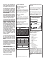
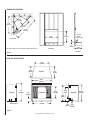
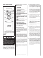
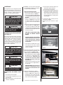
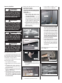
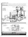
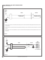
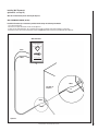
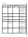
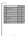
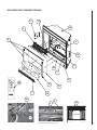
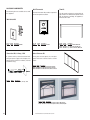
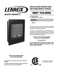
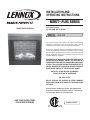
INSTALLATION AND
OPERATING INSTRUCTIONS
MERIT® PLUS SERIES
LENNOX HEARTH PRODUCTS
33" Electric Fireplace
P/N 850,032M REV. A 02/2006
MODEL: MPE-33R
This manual will enable you to obtain a safe, efficient and dependable
installation and operation of your electric fireplace. Please read and
understand these instructions before beginning your installation.
Do not alter or modify this fireplace or its components under any circumstances. Any modification or alteration of the fireplace system, including
but not limited to the fireplace and accessories, may void the warranty,
listings and approvals of this system and could result in an unsafe and
potentially dangerous installation.
IMPORTANT! IF OPTIONAL GLASS DOORS ARE PURCHASED, TO
ASSURE PROPER ALIGNMENT, INSTALL THIS FIREPLACE IN A
SQUARE AND PLUMB CONDITION, USING SHIMS AS NECESSARY
AT SIDES. THIS APPLIANCE IS MOUNTED ON RUBBER FEET TO
ENSURE ADEQUATE AIR CIRCULATION BENEATH FIREPLACE.
DO NOT BLOCK AIRFLOW AT THE BOTTOM AIR INTAKES.
INSTALLER: DO NOT DISCARD THIS MANUAL
PLEASE LEAVE FOR THE HOMEOWNER
FOR YOUR SAFETY
DO NOT STORE OR USE GASOLINE OR OTHER FLAMMABLE
VAPORS AND LIQUIDS IN THE VICINITY OF THIS OR ANY OTHER
APPLIANCE.
A French manual is available upon request. Order P/N 850,032CF
Ce manuel d’installation est disponible en francais, simplement en
faire la demande. Numéro de la pièce 850,032CF.
SAVE THESE INSTRUCTIONS
FOR FUTURE REFERENCE
®
C
NOTE: DIAGRAMS & ILLUSTRATIONS NOT TO SCALE.
Report # C1482763
US
1
CONGRATULATIONS!
CAUTION
In selecting this DAVE LENNOX Merit Plus electric fireplace, you have chosen the finest
and most dependable fireplace found anywhere. A beautiful and prestigious addition to
the finest homes. Welcome to a Family of hundreds of thousands of satisfied LENNOX
Fireplace Owners.
Please read and carefully follow all of the instructions found in this manual. Please
pay special attention to the safety instructions provided in this manual. The instructions included here will assure that you have many years of dependable and enjoyable
service from your LENNOX product.
TABLE OF CONTENTS
PACKAGING LIST
Packaging List...................................Page
This assembled Electric Room Heater is
packaged with:
2
•
Introduction ......................................Page
One accessory package located in the
firebox, containing;
2
1. One Installation and Operation Manual.
2. One Warranty Certificate.
3. One Remote Control.
General Information ..........................Page
3
Locating Fireplace .............................Page
•
3
Tools/Supplies Required .................. Page
3
Framing Specifications ..................... Page
4
Fireplace Specifications.................... Page
4
Clearances ....................................... Page
5
Pre-installation ................................. Page
5
Installation Steps ............................. Page
5
Electrical Connections ...................... Page
5
Final Finishing .................................. Page
6
Break-In Period ................................ Page
6
Control Panel Operation ................... Page
6
Remote Control Operation ............... Page
7
Maintenance..................................... Page
8
WARNING
If the information in this manual
is not followed exactly, an electrical shock or fire may result
causing property damage, personal injury or loss of life.
IMPORTANT
Please read and understand
these instructions before beginning your installation.
2
Two spare Light Bulbs are located in a
recess on the back of the log assembly.
INTRODUCTION
This Electric Fireplace is designed for
residential applications to be framed in
as a fireplace.
This appliance has been tested in accordance with UL 2021 and CSA C22.2 No.
46-M198 standards for fixed and location
dedicated electric room heaters.
Installation must conform to local codes.
In the absence of local codes, electrical
wiring and grounding must comply with
the National Electrical Code ANSI/ NFPA
70 - latest edition. In Canada, the current CSA C22-1 Canadian Electrical Code
- latest edition.
IMPORTANT
Before starting your fireplace
installation, read this installation and operation manual
very carefully to ensure you
understand it completely and in
entirety. Failure to follow these
instructions may result in a possible electric shock, fire hazard
and/or injury or property damage
and will void the warranty.
NOTE: DIAGRAMS & ILLUSTRATIONS NOT TO SCALE.
This appliance is mounted on
rubber feet. The purpose of these
feet is to ensure adequate air
circulation beneath the fireplace.
Do not remove these feet. Do not
install the fireplace directly onto
a carpet, rug, furniture or similar
surfaces, which could hinder or
block the airflow.
CAUTION
Extreme caution is necessary
when any heater is used by or
near children or invalids and
whenever the heater is left operating and unattended.
TO PREVENT A POSSIBLE FIRE, DO NOT
BLOCK AIR INTAKES OR EXHAUSTS IN
ANY WAY. DO NOT USE NEAR SOFT
SURFACES, LIKE A PILLOW, WHERE
OPENINGS MAY BECOME BLOCKED.
THIS APPLIANCE MAY BECOME HOT
WHEN IN USE. TO AVOID BURNS, DO NOT
LET BARE SKIN TOUCH HOT SURFACES.
KEEP COMBUSTIBLE MATERIALS, SUCH
AS FURNITURE, PILLOWS, BEDDING,
PAPERS, CLOTHES AND CURTAINS AT
LEAST 3 FEET (1 METER) FROM THE
FRONT OF THIS APPLIANCE.
DO NOT OPERATE ANY HEATER WITH
DAMAGED WIRING OR CONNECTORS,
OR AFTER THE APPLIANCE MALFUNCTIONS, OR IF IT HAS BEEN DROPPED OR
DAMAGED IN ANY WAY.
ANY REPAIRS TO THIS FIREPLACE
SHOULD BE PERFORMED BY A QUALIFIED
SERVICE TECHNICIAN.
UNDER NO CIRCUMSTANCES SHOULD
THIS FIREPLACE BE MODIFIED. PARTS
HAVING TO BE REMOVED FOR SERVICING
MUST BE REPLACED PRIOR TO OPERATING THE FIREPLACE AGAIN.
DO NOT USE THIS APPLIANCE OUTDOORS. DO NOT EXPOSE FIREPLACE TO
THE ELEMENTS (SUCH AS RAIN, ETC.).
THIS APPLIANCE IS NOT INTENDED FOR
USE IN BATHROOMS, LAUNDRY AREAS
OR SIMILAR INDOOR LOCATIONS. NEVER
LOCATE THIS APPLIANCE WHERE IT
COULD FALL INTO A BATHTUB OR OTHER
WATER CONTAINER.
DO NOT RUN ELECTRICAL WIRING OR
POWER CORD (OPTIONAL) UNDER CARPETING. OR COVER WITH THROW RUGS,
RUNNERS OR SIMILAR MATERIALS.
(FOR 120 V W/OPTIONAL POWER CORD)
AVOID THE USE OF AN EXTENSION CORD
BECAUSE THE EXTENSION CORD MAY
OVERHEAT AND CAUSE A RISK OF FIRE.
HOWEVER, IF YOU HAVE TO USE AN
EXTENSION CORD, THE CORD SHALL BE
NO. 14 AWG MINIMUM SIZE AND RATED
NOT LESS THAN 1800 WATTS, 15 AMPS.
THE EXTENSION CORD MUST BE A THREE
WIRE CORD WITH GROUNDING TYPE
PLUG AND CORD CONNECTION.
THIS APPLIANCE HAS HOT AND ARCING
OR SPARKING PARTS INSIDE. DO NOT
USE IT IN AREAS WHERE GASOLINE,
PAINT OR FLAMMABLE LIQUIDS ARE
USED OR STORED.
THIS FIREPLACE SHOULD NOT BE USED
AS A DRYING RACK FOR CLOTHING,
NOR SHOULD CHRISTMAS STOCKINGS
OR OTHER DECORATIONS BE HUNG
NEAR IT.
USE THIS APPLIANCE ONLY AS DESCRIBED
IN THIS MANUAL. ANY OTHER USE IS NOT
RECOMMENDED BY THE MANUFACTURER
AND MAY CAUSE A FIRE, ELECTRIC SHOCK
OR INJURY TO PERSONS.
IF APPLIANCE IS TO BE DISCONNECTED,
TURN OFF CONTROLS FIRST.
GENERAL INFORMATION
Power Supply Wire Specifications
120 Volt, 60 Hz, 1600 Watts:
(ref. Page 10)
Use two conductor, non-metallic sheath cable
with ground wire for the incoming power
supply. The wire used must conform to local
and national electrical codes for the specified
power consumption rating. See Table 1.
240 Volt, 60 Hz, 3000 Watt:
(ref. Page 11)
Use three conductor, non-metallic sheath
cable with ground wire for the incoming power
supply. The wire used must conform to local
and national electrical codes for the specified
power consumption rating. See Table 1.
LOCATING YOUR MERIT PLUS ELECTRIC
FIREPLACE
Your new fireplace may be installed into existing
framing or built into a wall (see Figure 1), or
set in a freestanding mantel cabinet available
from your dealer (see Page 17).
When choosing a location for your new fireplace, ensure that the general instructions are
followed. Also, for the best effect, install the
fireplace out of direct sunlight and away from
overhead lighting. See Figure 1.
Top View Showing Approved
Room Locations of Fireplace
Wall Switch or Wall Thermostat Kits
(optional kits, see Page 17)
Low voltage wire is provided for the wall switch
connection. The wires gage requirements are
shown on Table 1.
fireplace shown in gray.
WARNING
Do not install or operate this fireplace through a switch wired in the
120 V AC or 240 V AC circuits. The
only approved wiring for a switch
is through the low voltage circuit
(24 V AC) as shown on Page 14.
Power Supply Wire Gage
Voltage
Wire Gage
Fuse
Rating
120 V
14 GA.
15 AMP
240 V
14 GA.
20 AMP
Wall Switch / Thermostat Wire Gage
Voltage
Wire Gage
5 VOLTS
18 GAGE
Figure 1
TOOLS AND BUILDING SUPPLIES
NORMALLY REQUIRED
Tools:
Phillips Screwdriver
7/16" Socket Drive
Hammer
Saw And/or Saber Saw
Level
Measuring Tape
Plumb Line
Electric Drill And Bits
Pliers
Square
Gloves
Building Supplies:
Framing Materials
Wall Finishing Materials
Caulking Materials
(noncombustible)
Table 1
IMPORTANT NOTE: This fireplace system
is not difficult to install. However, in the
interest of safety, it is recommended that
the installer be a qualified or certified
“tradesman” familiar with commonly
accepted fireplace installation and safety
techniques as well as prevailing local
codes.
DO NOT INSERT OR ALLOW FOREIGN
OBJECTS TO ENTER ANY VENTILATION
OR EXHAUST OPENING, AS THIS MAY
CAUSE AN ELECTRIC SHOCK, FIRE, OR
DAMAGE TO THE APPLIANCE.
SAVE THESE INSTRUCTIONS.
NOTE: DIAGRAMS & ILLUSTRATIONS NOT TO SCALE.
3
FRAMING SPECIFICATIONS
25 5/8 "
(651 mm)
36 1/4 "
(921 mm)
35 1/4 "
(895 mm)
51 1/4 "
(1302 mm)
Electrical
Junction
Box
Electrical
Junction
Box (left side)
32 "
(812 mm)
35 1/4 "
(895 mm)
Corner View
4"
(102 mm)
Front View
Note: Framing dimensions are calculated for a nailing flange depth of 1/2"
15 1/8 "
(384 mm)
Side View
Figure 2
FIREPLACE SPECIFICATIONS
21 1/8 "
(537 mm)
13 3/4"
(350 mm)
Top View
14 7/8"
(32 mm)
34 1/2"
(876 mm)
Left Side
32 "
(812 mm)
5 1/8 "
(130 mm)
Front View
21 1/8 "
(537 mm)
24 1/2"
(622 mm)
Right Side
27 1/2 "
(700 mm)
Electrical Access
33 "
(838 mm)
Figure 3
4
NOTE: DIAGRAMS & ILLUSTRATIONS NOT TO SCALE.
5 1/4 "
(134 mm) 2 1/4 "
(55 mm)
29 3/4 "
(754 mm)
FIREPLACE SPECIFICATIONS
Cat. No. H3427
Model: MPE-33R
Description: Merit Plus Electric Fireplace,
33” Radiant
Shipping Weight: 81 lb.'s (36.75 KG)
Packaging:
41” x 17 3/4” x 33 1/2”
(1040 mm x 451 mm x 850 mm)
14.1 cu. ft.
Power Requirements:
(120 Volt, 60 Hz.)
Rated Wattage - 1600 Watts
Amperage - 13.33 Amps
(240 Volt, 60 Hz.)
Rated Wattage - 3000 Watts
Amperage - 12.5 Amps
Blower CFM: 83 CFM
(120 V): 5,461 BTU/HR
(240 V): 10,239 BTU/HR
MINIMUM CLEARANCES TO COMBUSTIBLES
This appliance is an electric fireplace designed
to be framed in with combustible materials (up
to the edge of the appliance). A drywall lip at
the top of the fireplace and 4 nailing flanges
on the sides of the appliance is provided to
facilitate installation.
IMPORTANT
Cold climate installation recommendation: when installing this
fireplace against a non-insulated
exterior wall or chase, it is
mandatory that the outer walls
be insulated to conform to applicable insulation codes.
WARNING
To prevent contact with sagging or loose insulation, the
appliance must not be installed
against vapor barriers or exposed
insulation. Localized overheating could occur and a fire coudld
result. Insulation and a vapor
barrier should be placed a
minimum of 2 inches from the
appliance.
PRE-INSTALLATION
Before You Start
Check appliance for any concealed damage.
DETAILED INSTALLATION STEPS
Sides:
Floor:
Top:
0 mm - 0 inches
0 mm - 0 inches
0 mm - 0 inches
Table 2
Mantel Clearance: Combustible and Non-combustible mantels may be installed at any height
above the top of the face of fireplace.
Hearth Protection: A hearth is not mandatory,
but it is recommended for aesthetic purposes.
Secure the hearth extension to the floor to
prevent possible shifting. Do no block the airflow beneath the appliance (read the following
WARNING).
1. Complete the framing opening to the dimensions specified in Figure 2.
2. Ensure that there is a minimum of 8" of
service cable for connection to the junction
box on the fireplace. Remove the outer jacket
and strip the individual wires 1/2" from the
end.
3. Loosen the screw securing the junction box
cover and remove the cover.
4. Position the fireplace into the framed-in
opening. Attach fireplace to frame using
nailing flanges provided.
5. Complete the wiring to the fireplace for the
appropriate voltage (120 V or 240 V), as
shown on Pages 10 & 11. Wires L1, L2, N
& G are attached to the rear of the junction
box cable clamp for easy access.
WARNING
6. Wire a dedicated, properly fused circuit with
an Amp rating for the appropriate voltage
(120 V - 15 Amps or 240 V - 20 Amps). A
dedicated circuit is required to prevent overloading a house circuit in cases of having
multiple appliances on the same circuit.
Use an outlet that is protected by a ground
fault circuit interrupter where required by
electrical code.
7. (If applicable) Make wall mount wall switch
or wall thermostat connections as outlined
on Pages 11 & 12.
8. Place all connectors inside the fireplace and
replace the junction box cover, ensuring
that the cable clamp grips only the jacket
of service, and if applicable, wall switch or
thermostat lines.
9. Perform a function test. See Manual Control
Panel Operation on Page 6 and Remote
Control Operation on Page 7.
ELECTRICAL CONNECTIONS
Refer to the electrical diagrams on Pages 10
to 14.
WARNING
Electrical wiring must comply
with local building codes and
other applicable regulations to
reduce the risk of fire, electrical
shock and injury to individuals.
IMPORTANT
Any electrical re-wiring of this
appliance must be done by a
qualified electrician.
WARNING
Do not use this fireplace if any
part of it has been underwater.
Immediately call a qualified
service technician to inspect the
fireplace and replace any part of
the electrical system which has
been under water.
This appliance is mounted on
rubber feet to ensure adequate
air circulation beneath fireplace.
Do not block airflow at the bottom
air intakes.
NOTE: DIAGRAMS & ILLUSTRATIONS NOT TO SCALE.
5
FINAL FINISHING
Materials such as brick and tile can be extended
down to the top of the fireplace. Do not extend
down, covering the outlet or glass enclosure
panel (optional kit).
There are a wide variety of “finished looks” for
these fireplaces, from formal wall decor with
elaborate mantels to rustic wood paneling or
warm brick facings.
Note: Ensure the circuit breakers for the power
supply are turned on.
This appliance can be operated either from the
manual control panel (see Figures 4 & 5) or
by using the remote control, wall switch or wall
thermostat (optional kits).
The manual controls are located on the firebox
floor on the front left (see Figure 5). If an
optional glass enclosure is installed, it must
be removed to access.
Main Power ON/OFF Switch
When the main power switch is turned on, power
is supplied to the fireplace. This switch must be
on for all other switches to operate.
Heater ON/OFF Switch
When this switch is turned on, the heater will
emit heat in the temperature range selected (see
Figure 6; G, H & I). The fireplace can operate
with or without heat.
Flame / Ember On/Off Switch:
Turns lights on inside ember bed and flame
cylinder.
Mantel Cabinet or Accent Trim Installations
An optional mantel cabinet kit or an accent trim
kit is available from your dealer (see Page 18).
These options give the appliance an attractive
finished look.
MANUAL CONTROL PANEL
Main Power On/Off (rear most switch)
On
•
Off
Hearth
Heater On/Off (center switch)
An aesthetically pleasing fireplace hearth can
be installed, if desired (see hearth protection
on Page 5).
On
•
Off
BREAK-IN PERIOD:
Flame / Ember On/Off (front most switch)
During the first few initial uses of this heater,
there may be a release of a slight, harmless odor.
This odor is a normal occurrence caused by the
initial heating of the internal heating elements
and should not reoccur.
On
Off
•
When using the main power on/off
switch inside the body, the power on/off
switch outside the body (optional wall
switch kit) must be in the OFF position.
When using power on/off switch outside
the body (optional wall switch), the
power on/off switch inside the body
must be in the OFF position.
When using the remote control, the
power on/off switch inside the body
and the wall switch (optional kit) must
be on the OFF position.
Figure 4
MANUAL CONTROL PANEL OPERATION
(refer to Figures 5 & 6)
Once this appliance has been properly installed
and connected to the power supply as defined
in this manual, it is ready to operate.
Manual Control Switches
are located behind pull
screen on inside floor
Figure 5
6
NOTE: DIAGRAMS & ILLUSTRATIONS NOT TO SCALE.
REMOTE CONTROL OPERATION:
The functions identified on the remote (see
Figure 6) are as follows:
REMOTE CONTROL
A
B
C
POWER
ON/OFF
D
F
DISPLAY
ON/OFF
Dimmer
Brighter
EMBERS
HEATER
G
H
ON/OFF
TEMP. CONTROL
HIGH
MED. LOW
I
FLAME
LOWER
HIGHER
J
•
E
K
When using the remote control, the power
on/off switch inside the body and the wall
switch (optional kit) must be on the OFF
position.
Figure 6
CAUTIONS
• Do Not Use Old Batteries With
New Ones.
• Do Not Use Batteries Other That
The Type Specified (2 Ea. AA).
• Ensure Batteries Are Correctly
Installed In Remote Control.
The Merit Plus Electric Fireplace is provided
with an Infrared light Remote Control.
All functions of the fireplace can be controlled through the remote control. Note:
The Effective range of the remote control
is up to approximately 26 feet (8 meters).
A. POWER BUTTON
Press once to turn on power to fireplace.
B. INDICATING LIGHT
Illuminates when signal is sent.
C. LIGHT BUTTON
On/off switch for flame and ember light.
D. LIGHT ADJUSTING BUTTON (DIM)
Reduces brightness of embers.
E. LIGHT ADJUSTING BUTTON (BRIGHTEN)
Increases brightness of embers.
F. HEATER ON/OFF
This button will turn the heater ON and OFF
independent of the main button.
G. TEMPERATURE ADJUSTMENT BUTTON
(HIGH)
Highest heat output, up to 86° F.
H. TEMPERATURE ADJUSTMENT BUTTON
(MED.)
Medium heat output, up to 75° F.
I. TEMPERATURE ADJUSTMENT BUTTON
(LOW)
Lowest heat output, up to 64° F.
J. FLAME ADJUSTING BUTTON (LOWER)
Reduces flame intensity.
K. FLAME ADJUSTING BUTTON (HIGHER)
Increases flame intensity.
Remote Control Operation Steps:
1. To control the electric fireplace by remote
control, the main power on/off switch
should be in the off position. This switch is
located on the front left floor of firebox (see
Figures 4 & 5).
2. When operating the remote control, it must
be pointed at the logs inside the electric
fireplace and a beep must be heard each time
you press a function button. The beep lets
you know the remote control is operating the
function button you are pressing.
3. Remote On & Off Button - The button on the
top left (see A) is the on/off power button.
When pressing this button you will hear a
beep, this will activates the power to the
fireplace. You must then press the display
button (B) to activate the lights.
Note: If the flame does not come on immediately, adjust brightness and intensity (buttons
E & K).
NOTE: DIAGRAMS & ILLUSTRATIONS NOT TO SCALE.
4. To increase the brightness, press and release
the light brighten button (see E). Each time
you press this button you will hear a beep,
and the brightness will increase by a small
amount, until the maximum brightness
is achieved. To decrease the brightness,
press and release the light dimming button
(see D). Each time you press this button
you will hear a beep, and the brightness
will decrease by a small amount, until the
minimum brightness is achieved.
5. Heater Button, To activate the heater, press the
heater button (see F), then press HI (G),
MED (H), or LO (I). The heater is preset to
the following temperatures:
• HIGH will shut off when room reaches
approximately 86° F (30° C).
• MED. will shut off when room reaches
approximately 75° F (24° C).
• LO. (Low) will shut of when room reaches
approximately 64° F (18° C).
6. Flame Button - Press the Flame Adjusting
Buttons to achieve a higher or lower flame
intensity (see J & K).
7. To Increase Flame Brightness press and
release the (K) button. Each time you press
this button you will hear a beep and the
brightness of the flame will increase slightly,
until the maximum setting is reached. To
Decrease Flame Brightness press and
release the (J) button. Each time you press
this button you will hear a beep and the
brightness of the flame will decrease slightly,
until the minimum setting is reached.
8. To turn the electric fireplace off, Press the off
button once (A), when you hear the beep the
fireplace will be completely off. When you
restart your fireplace with the remote control,
all settings will restart at the high settings programmed at the factory. You may also simply
press the (B) button to turn off the flame and
still use the heater.
7
MAINTENANCE
This appliance has been designed to provide
many years of trouble-free service. The components that will need to be serviced have been
kept to a minimum. Periodic dusting of the
fireplace is all that should be required.
CAUTION
Disconnect power before attempting any maintenance or cleaning
to reduce the risk of fire, electrical shock or personal injury.
WARNING
When cleaning the fireplace, the
fireplace must be cool.
4. OPTIONAL: To ensure that the brick panel
isn't accidentally scratched, you may wish
to remove it before proceeding:
Brick Panel Removal Procedure:
a. Remove the 2 screws on the front of the
grate. Remove Grate (see Figure 8).
b. Lift out Log / Ember assembly and set
aside. Caution: Be careful not to scratch
the finish.
c. Remove the top brick panel retaining
bracket (see Figure 15). Be very careful
to hold the bracket when removing the
2 screws to ensure the bracket doesn't
fall.
d. Remove the left and right side brick panel
retaining brackets (see Figure 15). Be
very careful to hold the bracket when
removing. Remove the bottom screw first
to avoid the frame falling down after both
screws are removed.
b. Turn the power and heater switches on
and check for proper operation.
c. Turn off power to the fireplace.
d. Using one hand to hold the handle of the
heater/blower assembly, slowly push it
back up and line up the holes for the 5
screws. Install the 5 screws to secure
the new heater/blower assembly to the
mounting plate.
7. (If brick panel was removed) Reverse
instructions on Step 4.
8. Reinstall glass panel enclosure, if applicable.
Grate
CLEANING THE GLASS ENCLOSURE PANEL
(OPTIONAL KIT)
Over time the front glass panel may become
dirty or dusty. Dust can be removed by lightly
rubbing the glass surface with a clean, lint free
cloth or paper towel. To remove fingerprints
or other marks, use a damp cloth with a good
quality household glass cleaner. The front glass
panel should be completely dried with a clean,
lint free cloth or paper towel.
CAUTION
Do not use abrasive cleaners on
the glass panel. Do not spray
liquids directly onto any surface
of the fireplace.
WARNING
An authorized service representative should perform any other
servicing.
CAUTION
Handle glass very carefully to
prevent accidental breakage.
HEATER/BLOWER REPLACEMENT PROCEDURE
8
1. Turn off power to the fireplace.
2. Let the fireplace completely cool, if it has
been operating.
3. Open the steel curtains (remove glass panel
enclosure, if applicable).
TAKE CARE TO HOLD BRICK PANEL
IN PLACE TO PREVENT POSSIBLE
DAMAGE.
Figure 8
Suggestion: Slide the screens toward the
middle of the fireplace for easier access
to the screws on the sides. Return the
screens to the sides before proceeding
to instruction f.
Heater/blower Mounting Plate
Handle
e. Tip brick panel forward from the top,
just enough to clear screens. Carefully
remove brick panel from firebox and set
aside in a safe place.
5. Remove the screws which secure the heater
blower mounting plate using a phillips screwdriver as follows (see Figures 9 & 10):
a. While using one hand to hold the handle
of the heater/blower assembly (see Figure
9), remove the 5 screws which secure
the mounting plate. Remove the 4 side
screws first (2 on each side). Remove
the middle screw that is on the top of
the handle last.
b. Slowly lower the heater/blower assembly
and let it rest on the 2 support chains (1
on each side).
Brick Panel
Remove screws indicated by arrows
Figure 9
Heater/blower Mounting Plate
Be careful not to
damage brick panel
Figure 10
IMPORTANT NOTE: Label all wire locations prior to disconnecting to ensure
that wires are reconnected in the correct
positions.
6. Replace the heater/blower as follows:
a. Replace the old heater/blower with the
new one. Note: when replacing the
heater/blower, ensure that all the wires
on the heater are correct, otherwise the
heater will not function properly.
NOTE: DIAGRAMS & ILLUSTRATIONS NOT TO SCALE.
Blower / Heater
Figure 11
Replacing Light Bulbs
WARNING
The fireplace must be unplugged/
disconnected from the power
supply prior to any maintenance
or cleaning in order to reduce the
risk electric shock or fire.
WARNING
The halogen light bulbs in your
fireplace can become extremely
hot. Allow at least 10 minutes
between turning off the fireplace
and removing light bulbs to avoid
the accidental burning of skin.
6. Remove spare bulbs from the recess on the
back of the log assembly.
Acess bulbs as follows:
Use gloves or cloth when handling bulbs to
prevent oils from your skin damaging bulbs
when heated.
a. Ember Bed Bulbs i. With the ember bed removed, the 2
ember bed light bulbs will be visible
(see Figures 13 and 14).
ii. Lift off spring from bulb tips, then hold
socket and pull out to remove. Install
new bulbs into sockets by pressing them
in (while holding the socket), Install
retaining spring over each bulb tip.
iii. Plug in power cord or connect power to
appliance. Turn on power to test bulbs.
Disconnect power.
iv. Reverse steps 3 to 5.
Log/Ember Assembly
CAUTION
Do not exceed a 35 Watt bulb.
Use of a higher rated bulb may
result in a fire, causing property
damage, personal injury or loss
of life.
Figure 12
Grate
Ember Bed
CAUTION
Bulb
Do not touch the bulbs, oils from
your skin will damage them
when they heat up. Use gloves
or cloth when handling bulbs.
Bulb Replacement Procedure:
Figure 13
1. Turn off power to the fireplace.
2. Let the fireplace cool, if it has been operating.
3. (If optional glass panel enclosure is
installed) Remove glass panel per instructions provided in kit.
4. Remove the 2 screws on the front of the
grate (see Figure 12. Also see item #7 on
Page 17). Remove Grate.
5. Lift out log/ember assembly by tilting forward and firmly pulling on back of ember
bed assembly. It should pop out from
track and lift out. Caution: Be careful not
to scratch the finish.
Flame Panel
Figure 16
iii. Locate flame cylinder drum (see Figure
17). Squeeze one half of drum cylinder
until its top edge clears the top drum
track. Remove the bottom edge of
the cylinder drum from the bottom
drum track. Once you have removed
one half of the drum cylinder, you will
have access to the 2 light bulbs (see
Figure 18). Note: do not exert excessive pressure on the drum cylinder as
this may cause damage.
v. Lift off spring from bulb tips, then hold
socket and pull bulb out to remove.
Install new bulbs into sockets by
pressing them in (while holding the
socket), Install retaining spring over
each bulb tip.
7. Reinstall all components that were removed
(reverse Steps 1-5).
Bulb
• 2 bulbs provide illumination for the ember
bed and 2 bulbs provide illumination for the
flame generation assembly (bulbs are rated at
35 Watts Max., Halogen, GX6.35).
• 2 spare bulbs are located in a recess on the
back of the log assembly.
ii. using a phillips screwdriver, remove
the flame panel (see Figure 16).
Figure 14
Flame Cylinder Drum
b. Flame Cylinder Bulbs
i. Remove Brick panel, following procedure on Page 8 (see Brick panel Removal
Procedure).
Brick Panel
Retaining brackets
Figure 15
NOTE: DIAGRAMS & ILLUSTRATIONS NOT TO SCALE.
Figure 17
Bulbs
Figure 18
9
WIRING DIAGRAM - 120 VOLT
Wiring diagrams are provided here for reference purposes only. This information is also provided on schematics attached directly to the appliance
on the left side.
CAUTION: LABEL ALL WIRES PRIOR TO DISCONNECTION WHEN SERVICING CONTROLS. WIRING ERRORS CAN CAUSE IMPROPER AND DANGEROUS APPLIANCE OPERATION.
Outside Switches
L1 = BLACK (POWER)
L2 = BLACK (POWER)
G = GREEN (GROUND)
N = WHITE (COMMON)
N1 = WHITE (COMMON)
N2 = WHITE (COMMON)
Wall Thermostat
Wall Switch
(power on/off)
Control Panel Control Panel
(power on/off) Flame / Ember
On/Off Switch
Control Panel
Heater On/Off
Switch
P
SIP11
T-P
SIP7
SIP13
L-R1
GROUND
N-LIGHT
SIP13
SIP3
Circuit
Board
POWER-N
N-M
N-FAN
TEM.
K-H
N
N
N1
SIP6
Heater 1 (L)
L-R2
SIP4
Heater 2 (L)
K-P
L2
L-FAN
SIP2
Fan Motor (L)
REMOTE
N2
L-M
Relay 2
HOME POWER
SUPPLY
120 V AC.
L-LIGHT
Relay 1
MAIN POWER
L-FLAME
Light (L)
Flame Motor (L)
N-FLAME
P-L
P-TRA.
GROUND
Transformer
L
L1
t104° C t90°C
Temperature Sensor
Remote Sensor
Figure 19
WIRING - 120 VOLT
See Power Supply Specifications on Page 3.
WHITE
N
BLUE
BLUE
HOME POWER SUPPLY 120 V AC.
L1
120 V AC
BLACK
ORANGE
GROUND
Figure 20
YELLOW AND GREEN
N
N1
N2
L1
FIREPLACE WIRE
HARNESS
L2
GROUND
120 V 1600W
WARNING
Do not install or operate this fireplace through a switch wired in the 120 V AC or 240 V AC circuits. The only approved
wiring for a switch is through the low voltage circuit (24 V AC) as shown on Page 14.
10
NOTE: DIAGRAMS & ILLUSTRATIONS NOT TO SCALE.
WIRING DIAGRAM - 240 VOLT
Wiring diagrams are provided here for reference purposes only. This information is also provided on schematics attached directly to the appliance
on the left side.
CAUTION: LABEL ALL WIRES PRIOR TO DISCONNECTION WHEN SERVICING CONTROLS. WIRING ERRORS CAN CAUSE IMPROPER AND DANGEROUS APPLIANCE OPERATION.
Outside Switches
L1 = BLACK (POWER)
L2 = BLACK (POWER)
G = GREEN (GROUND)
N = WHITE (COMMON)
N1 = WHITE (COMMON)
N2 = WHITE (COMMON)
Wall Switch
(power on/off)
Control Panel
Heater On/Off
Switch
Wall Thermostat
Control Panel Control Panel
(power on/off) Flame / Ember
On/Off Switch
SIP11
SIP13
N
N
GROUND
N-LIGHT
SIP3
TEM.
POWER-N
N-M
N-FAN
SIP6
K-H
T-P
Circuit
Board
L-R1
SIP7
N1
L-R2
SIP4
Heater 1 (L)
K-P
Heater 2 (L)
REMOTE
SIP2
HOME POWER
SUPPLY
240 V AC.
L2
L-FAN
Relay 2
L1
Fan Motor (L)
L-M
Relay 1
MAIN POWER
L2
N2
L-LIGHT
N-FLAME
Light (L)
Flame Motor (L)
L-FLAME
P-L
P-TRA.
GROUND
Transformer
L1
t104° C t90°C
Temperature Sensor
Remote Sensor
Figure 21
WIRING - 240 VOLT
See Power Supply Specifications on Page 3.
L1
HOME POWER SUPPLY
240 V AC.
120V (L1) + 120V (L2) = 240V
WHITE
N
L2
GROUND
N
120 V AC.
BLACK
L1
120 V AC.
ORANGE
L2
BLUE
N1
BLUE
N2
YELLOW AND GREEN
FIREPLACE WIRE
HARNESS
GROUND
240 V 3000W
Figure 22
WARNING
Do not install or operate this fireplace through a switch wired in the 120 V AC or 240 V AC circuits. The only approved
wiring for a switch is through the low voltage circuit (24 V AC) as shown on Page 14.
NOTE: DIAGRAMS & ILLUSTRATIONS NOT TO SCALE.
11
WALL THERMOSTAT & WALL SWITCH WIRING DIAGRAMS
(optional kits, see Page 18)
5V
OUTSIDE
INSIDE
RED
POWER ON/OFF SWITCH
POWER ON/OFF SWITCH
(ON CONTROL PANEL)
(OPTIONAL WALL SWITCH)
GREEN
RED
GROUND
•
When using the main power on/off switch inside the body, the power on/off switch outside the body (optional wall switch kit) must be in
the OFF position.
•
When using power on/off switch outside the body (optional wall switch), the power on/off switch inside the body must be in the OFF
position.
•
When using the remote control (optional kit), the power on/off switch inside the body and the wall switch (optional kit) must be on the
OFF position.
Figure 23
5V
OUTSIDE
INSIDE
WALL
THERMOSTAT
BLACK
A#D
WHITE
GREEN
1K Ω POTENTIOMETER
GROUND
Figure 24
12
NOTE: DIAGRAMS & ILLUSTRATIONS NOT TO SCALE.
Installing Wall Thermostat
(optional kit, see Page 18)
Wire the wall thermostat prior to installing the fireplace.
WALL THERMOSTAT WIRING (24 VAC):
Install Wall Thermostat per instructions provided with kit and per the following information:
1. Turn off circuit breaker.
2. Remove cover plate located on the left side of appliance.
3. Locate the the black and white wires and pull out the length needed to reach wall thermostat (15 feet max.).
4. Connect the wires to the wall thermostat as shown in Figure 25. Follow instructions provided with wall switch kit.
Wall Thermostat
60
50
70 80
90
Black
White
50
60 70 80 90
White
Left Side of
Fireplace
5V
Black
White
Black
Figure 25
NOTE: DIAGRAMS & ILLUSTRATIONS NOT TO SCALE.
13
Power On/Off Wall Switch Installation
(optional kit, see Page 18)
Wire the wall switch prior to installing the fireplace.
WALL SWITCH WIRING (24 VAC):
Install Wall Switch per instructions provided with kit and per the following information:
1. Turn off circuit breaker.
2. Remove cover plate located on the left side of appliance.
3. Locate the 2 red wires and pull out the length needed to reach wall switch (15 feet max.).
4. Connect the red wires to the wall switch as shown in Figure 26. Follow instructions provided with wall switch kit.
Red
Red
Red
Red
Red
5V
Red
Figure 26
14
NOTE: DIAGRAMS & ILLUSTRATIONS NOT TO SCALE.
TROUBLESHOOTING
SYMPTOM
POSSIBLE
CAUSES
WHO PERFORMS
CORRECTIVE ACTION
CORRECTIVE ACTION
1. Fireplace turns off and
will not turn on.
Fireplace has
overheated.
Homeowner
The appliance is protected with a
safety device to prevent it from
overheating. If the fireplace should
overheat, a thermal switch will
disconnect power to the unit and
will not come back on without
being reset. Reset it by turning
the main power switch off and
waiting 5 minutes then turning it
back on.
2. Flame is fixed
(unmoving).
Wiring may be loose
or the flame motor
may be defective.
Qualified Service Technician
Inspect all wiring for loose
connections. If the wire
connections are good, replace the
flame motor.
3. Dim or poorly visible
flame or log set and
ember is not glowing.
Light bulb(s) burnt out
or wiring is loose.
Homeowner
Inspect all wiring for loose
connections and repair or replace
if necessary. Inspect light bulbs
and replace if necessary.
4. Flame sputters.
Flame motor is
defective.
Qualified Service Technician
Replace flame motor.
5. Remote control does not
work.
Low batteries.
Homeowner
Replace AA batteries in remote
control. If problem persists, there
may have been a loss of power to
the unit as a possible result from a
power failure (i.e. breaker tripped).
Unit switch and/or
wall switch in “ON”
position.
Turn off main power on/off switch
(see Figure 4) and/or optional wall
switch (if applicable).
6. Circuit breaker trips or
fuse blows when the unit
is turned on.
Improper circuit
current rating.
Qualified Service Technician
NOTE: DIAGRAMS & ILLUSTRATIONS NOT TO SCALE.
Check the house circuit to ensure
it is on a dedicated circuit with
proper Amp. rating. If the circuit
breaker continues to trip (or blown
fuses), inspect wiring for a loose
connection or a dead short. Repair
or replace wiring and/or
connectors as necessary.
15
REPLACEMENT PARTS
ITEM
NO.
DESCRIPTION
MPE-33R
CAT. NO.
QTY
1
Bulb Kit, (10 Each 35w Halogen)
H1623
1
2
Side Frames, 1 Left And 1 Right
H1942
1
3
Circuit Board And Remote Control Sensor
H1625
1
4
Nailing Flange Kit, (4 Each)
H1626
1
5
Glass Brick Panel
H1943
1
6
Glass Retaining Bracket Kit: Left, Right, & Top
H1628
1
7
Grate For Log Assembly
H1944
1
8
Blower, Heating Element, And Access Panel Assembly
H1630
1
9
Flame Cylinder Assembly
H1631
1
10
Flame Motor
H1632
1
11
Lennox Logo Kit (1 Each)
12L15
1
12
Log Assembly And Ember Bed
H1945
1
13
Panel, Bottom, Front
H1946
1
14
Panel, Flame Cover
H1947
1
15
Panel, Louver, Upper Front
H1948
1
16
Panel, Upper Frame Top
H1949
1
17
Electrical Outlet Cover Plate
H1639
1
18
Screen Set, Pull
H1640
1
19
Switch, Toggle (1 Each)
H1641
1
20
Transformer
H1642
1
21
Wire Harness
H1643
1
22
Remote Control, Electric, Rce
H1644
1
Note: If touch-up paint is needed, use Rust-oleum®, Painter’s Touch, Flat Black (part number 1976) available at most stores which sell
aerosol touch-up paint.
16
NOTE: DIAGRAMS & ILLUSTRATIONS NOT TO SCALE.
REPLACEMENT PARTS COMPONENT DIAGRAMS
17
19
16
8
6
4
15
14
2
13
1
11
POWER
ON/OFF
ON/OFF
DISPLAY
Brighter
Dimmer
EMBERS
HEATER
22
6
ON/OFF
TEMP. CONTROL
HIGH MED. LOW
5
FLAME
LOWER
HIGHER
7
12
20
9
1
18
Front View
3
NOTE: DIAGRAMS & ILLUSTRATIONS NOT TO SCALE.
17
ACCESSORY COMPONENTS
The following items are available for use with
this appliance.
Wall Thermostat
Trim Kit
The wall thermostat kit provides temperature
control for optimum comfort.
This kit contains trim panels used to finish the
gaps between the wallboard or optional mantel
and the fireplace, providing the appliance a
finished built-in look.
Wall Switch Kit
Cat. No. Model
85L87 FWSK
Description
Wall Switch Kit, White
Cat. No. Model
89L36
WTK
Description
Wall Thermostat Kit
Power Cord Kit, 3-Prong, 110V
Glass Enclosure Kit
If a power cord is preferred instead of hardwiring the power supply to the fireplace, this
optional power cord kit is available (110 Volt
installations only).
These glass enclosure panels are a one-piece
panel, which have a bi-fold “look” as shown
below.
~83”
Cat. No. Model
H1645
PCK
Cat. No. Model
H3430 GEP-33BL
H3433 GEP-33PB
H3434 GEP-33BS
Cat. No. Model
Description
H3435 TK3-33BL 3-pc. Black Trim Kit, MPE-33R
H3436 TK3-33PB 3-pc. Brass Trim Kit, MPE-33R
H1932 TK3-33BS 3-pc. Stainless Trim Kit, MPE-33R
Description
Glass Enclosure Panel, Black on Bronze
Glass Enclosure Panel, Brass on Bronze
Glass Enclosure Panel, Stainless on Bronze
Description
Power Cord Kit, 3-Prong, 110V
Cat. No. Model Description
H3604 FFEP-33M 33" Decorative Complete Front Face, Mission Style
H3605 FFEP-33IA 33" Decorative Complete Front Face, Interlocking Arch
18
NOTE: DIAGRAMS & ILLUSTRATIONS NOT TO SCALE.
NOTE:
THIS PAGE
LEFT BLANK INTENTIONALLY
NOTE:
DIAGRAMS
& ILLUSTRATIONS
NOT TO SCALE.
19
The manufacturer reserves the right to make changes at any time, without notice, in design,
materials, specifications, prices and also to discontinue colors, styles and products.
Consult your local distributor for fireplace code information.
Printed in U.S.A. © LENNOX HEARTH PRODUCTS 2005
P/N 850,032M REV. A 02/2006
NOTE: DIAGRAMS & ILLUSTRATIONS NOT TO SCALE.
1110 West Taft Avenue
Orange, CA 92865