1
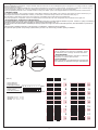
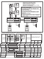
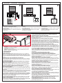
• Manuel d’installation pour kit portier vidéo numérique
• Installation manual for digital video door entry kits
• Inštalačný návod pre digitálny vstupný videosystém
3759 10 / 3759 20
2630 / 2
• Description
Kit portier vidéo numérique, image noir et blanc pour 1, 2, 3, 4 ou 6 logements (jusqu'à 18 logements avec des platines complémentaires). Câble
paire torsadée.
Réf.: 3759 10 (1 logement) Réf.: 3759 20 (2 logements).
• Description
b/w image digital video door entry kits for 1, 2, 3, 4, or 6 dwellings (up to 18 dwellings with the additional outdoor units). Twisted pair cable.
Cat No.: 3759 10 (1 dwelling) Cat No.: 3759 20 (2 dwellings).
• Popis
Digitálny vstupný Č/B videosystém pre 1, 2, 3, 4, alebo 6 bytových jednotiek (až do 18 pri použití prídavných vonkajších tlačidlových panelov).
Pripojenie pomocou krútenej dvojlinky (twisted pair).
Obj. č.: 375910 (1 byt) Obj. č.: 3759 20 (2 byty)
34,5
93
• Kit components:
• Sada obsahuje:
Platine de rue Série 7 image
noir et blanc
Réf.: 3759 18 (1 boutonpoussoir) / 3759 28 (2 boutonspoussoirs)
Series 7 b/w image outdoor
unit
Cat No.: 3759 18 (1 pushbutton) /
3759 28 (2 push-buttons)
9RQNDMãLDý%tlačidlová
MHGQRWND
2EMþWODþLGOi
WODþLGOi
• Sachet comprenant:
1 vis de fermeture Philips 4 x
8 mm
3 vis de fixation Philips
3,9 x 25 mm
3 chevilles de fixation Fischer
5 x 25 mm
• Bag containing:
1 4 x 8 mm Philips closing
screw
3 3.9 x 25 mm Philips fastening
screws
3 5 x 25 mm Fischer fixing pins
• SáčokREVDKXMH
NV8]DWYiUDFLDVNUXWND
[PP
NV8SHYĖRYDFLHVNUXWN\
3,9 x 25 mm.
NVHPRåGLQN\
[PP
• Interface de commande
numérique
Réf.: 3750 06
Interface de commande
numérique à monter sur un rail
DIN (10 modules)
• Digital control interface
Cat No.: 3750 06
Digital control interface for DIN
rail mounting
(10 modules)
• 'LJLWiOQDRYOiGDFLDFHQWUiOD
2EMþ
'LJLWiOQDRYOiGDFLDFHQWUiODSUH
PRQWiåQD',1OLãWXPRGXORY
• Gâche NT
Réf.: 3749 00
• NT door opener
Cat No.: 3749 00
• (OHNWULFNê]iPRN
2EMþ
1650
167
• Eléments du kit:
26,7
Sol/Floor/Podlaha
150
31
175
Central
Digital
88
88
175
E-35
DIN (10 mód)
DIN (10 mód)
• M-72 series 7 monitor(s)
Cat No.: 3744 20
Digital system, b/w image
B-72 wall base(s)
Cat No.: 3744 42
Digital system
• Fonctionnement du système
En appuyant sur le bouton-poussoir du poste extérieur,
l'appel retentit dans le logement mais aussi sur le
poste extérieur. C'est ce que l'on nomme confirmation
d'appel sur poste extérieur. La sonnerie est
électronique à trois tonalités. Dans le logement, le
moniteur s'allume et présente l'image de la personne
qui a sonné. Le propriétaire peut répondre à l'appel
et ouvrir la porte en utilisant la touche commande de
gâche … Le téléphone comporte la touche <O>
pour activer des fonctions auxiliaires, telles que
l'éclairage de l'escalier, et une touche de surveillance
0 qui active le moniteur sans recevoir d'appel.
L'éclairage de scène se fait grâce aux infrarouges.
Les platines de rue ne nécessitent pas
d'encastrement et leur design dernière génération
simplifie le montage et augmente la fiabilité en
améliorant la protection du système contre les
intempéries. Le connecteur sur l'interface de
commande numérique permet une connexion directe
des moniteurs afin de vérifier le bon fonctionnement
avant l'installation définitive.
219
• Videotelefón(y) M-72
Obj. č.: 3744 20
Digitálny systém, Č/B obraz
B-72 Montážna(e) doska(y) na
stenu Obj. č.: 3744 42
Digitálny systém
155
1600
• Moniteur(s) Série 7
M-72
Réf.: 3744 20
Système numérique, image
noir et blanc
Base(s) murale(s) B-72
Réf. : 3744 42
Système numérique
189
195
• Câble d'alimentation
E-35
Réf.: 3750 05
Câble d'alimentation
230 V ca, montage sur rail DIN
(10 modules)
• 1DSiMDFt]GURM(
• E-35 power supply cable
2EMþ
Cat No.: 3750 05
230 V AC power supply cable, 1DSiMDFt]GURM9$&PRQWiå
DIN rail mounting (10 modules) QD',1OLãWXPRGXORY
Sol/Floor/Podlaha
• System operation
When the outdoor unit push-button is pressed,
the call rings in the dwelling, and at the outdoor
unit. This is referred to as call confirmation at the
outdoor unit. The electronic chimes have three
tones. In the dwelling, the monitor comes on and
displays the image of the person who rang. From
the house, you can reply to the call and open the
door using the door release control. The telephone
set has a button <O> for activating the auxiliary
functions, such as the light in the staircase, and
a surveillance button 0 for activating the monitor
without receiving a call. The scene is lit with
infrared light.
The outdoor units are not flush-mounted and their
up-to-date design simplifies fitting and increases
reliability by improving the weatherproofing of the
system. The connector on the digital control
interface allows for direct monitor connection in
order to check proper operation before final
installation.
• Popis činnosti systému
Pri zatlačení tlačidla na vonkajšom tlačidlovom paneli je počuť zvonenie v byte aj na vonkajšom tlačidlovom paneli. Slúži pre potvrdenie zvonenia. Elekktronické zvonenie je trojtónové. V byte sa zapne
monitor a zobrazuje osobu, ktorá zvonila. Z bytu je
možné odpovedať na volanie a otvoriť dvere pomocou elektrického zámku. Videotelefón obsahuje
tlačidlo
slúžiace pre ovládanie pomocných
funkcií, napr. osvetlenie schodiska a tlačidlo pozorovania , ktorým je možné zapnúť zobrazenie
obrazu z kamery bez predošlého zvonenia.
Snímané miesto je osvetlené infračervenými
LED diódami.
Vonkajší tlačidlový panel sa montuje na povrch a
jeho moderné prevedenie zjednodušuje montáž a
zvyšuje spoľahlivosť a odolnosť systému voči
vplyvom počasia.
Konektor na centrálnej jednotke umožňuje priame
pripojenie videotelefónu aby sa mohla skontrolovať
správnu činnosť ešte pred finálnou montážou.
• Codage des moniteurs
Pour les installations numériques, chaque moniteur doit être codé avec le micro interrupteur qui lui correspond. Le codage se fait sur la partie
arrière du moniteur (Fig. 1).
Pour programmer le numéro d'identification du moniteur, il faut d'abord le convertir en numéro binaire. Se reporter à la table de conversion (Fig. 2).
C'est une opération délicate car si le micro-interrupteur se trouve à mi-chemin, le moniteur ne sera pas programmé.
Une fois l'opération terminée, il est conseillé de faire un test pour vérifier que le code d'appel attribué à ce bouton-poussoir est bien le bon.
• Monitor coding
For digital installations, each monitor should be coded with its matching push-button. The coding is done at the rear of the monitor (Fig. 1).
To program the monitor's identification number, you must first convert it to binary. Refer to the conversion table (Fig. 2).
This operation is delicate because, if the micro-switch is only halfway, the monitor won't be programmed.
Once the operation is completed, a test is recommended to check that the call code assigned to the push-button is the right one.
• Programovanie - kódovanie videotelefónov
Pri montáži digitálnych zariadení musí byť každý videotelefón spárovaný so zodpovedajúcim tlačidlom na paneli. Telefón sa spáruje s konkrétnym
tlačidlom zadaním príslušného binárneho kódu na zadnej strane videotelefónu (obr. 1)..
Pre naprogramovanie videotelefónov identifikačnými číslami je potrebné ich najprv skonvertovať do binárnej sústavy. Prevodná tabuľka a vysvetlenie je
na obr.2 .
Táto operácia je dôležitá pretože ak je mikroprepínač v medzipolohe, videotelefón bude nefunkčný.
Po vykonaní tejto operácie sa doporučuje vykonať test a preveriť, či sú volacie kódy priradené správnym tlačidlám.
(obr. 1)
• Très important.
Tous les moniteurs sont codés avec la valeur N°1. Suivez
les instructions pour le codage des autres moniteurs.
• Very important.
All monitors are coded with the value No. 1. Follow the
instructions to code the other monitors.
• Veľmi dôležité.
Všetky videotelefóny sú prednastavené na hodnotu N01
Pozri inštrukcie pre kódovanie viacerých videotelefónov.
.
(obr. 2)
• Valeur attribuée
• Value assigned
• Prislúchajúca hodnota
• Numéro de l'interrupteur
• Switch number
• Číslo mikro-prepínača
Nº
128 64 32 16
1
2
3
4
8
4
2
1
ON
5
6
7
8
OFF
• Exemple: 8 + 2 + 1 = 11
• Example: 8 + 2 + 1 = 11
• Príklad: 8 + 2 + 1 = 11
2
1
10
2
11
3
12
4
13
5
14
6
15
7
16
8
17
9
18
• Codage des moniteurs: Correspondance des boutons-poussoirs
Les boutons-poussoirs doivent être connectés aux bornes P1, P2 … P18 de l'interface de commande numérique. Le bouton-poussoir connecté
à la borne P1 appelle le moniteur codé P1, le bouton-poussoir connecté à la borne P2, le moniteur codé P2, etc.
• Monitor coding: push-button correspondence
The push-buttons must be connected to terminals P1, P2 … P18 of the digital control interface. The push-button connected to terminal P1 calls
the monitor coded P1, the push-button connected to terminal P2, the monitor coded P2, etc.
• Naprogramovanie videotelefónov: priradenie zodpovedajúcim tlačidlám
Tlačidlá musia byť pripojené ku svorkám P1, P2 ... P18 digitálnej ovládacej centrály. Tlačidlo pripojené ku svorke P1 volá videotelefón naprogramovaný kódom P1, tlačidlo pripojené ku svorke P2 videotelefón P2, atď. .
110
• Exemple correct
Le bouton-poussoir de la platine connecté à la
borne P9 de l'interface de commande numérique
appellera le moniteur codé N°9. Le boutonpoussoir de la platine connecté à la borne P15
de l'interface de commande numérique appellera
le moniteur codé N°15.
M
V
16
2
1
• Valid example
M
V
16
2
1
The outdoor unit push-button connected to terminal
P9 of the digital control interface will call the monitor
coded No. 9. The outdoor unit push-button
connected to terminal P15 of the digital control
interface will call the monitor coded No. 15.
• Príklad správneho zapojenia
Tlačidlo vonkajšej jednotky pripojené ku svorke
P9 digitálnej ovl. centrály bude volať videotelefón naprogramovaný hodnotou 9. Tlačidlo
pripojené ku svorke P15 centrály bude volať
videotelefón naprogramovaný hodnotou 15.
M-72
1 2 16 V M
DVPA
Obj.č.: 3744 72
1 2 16 V M
M
V
16
2
1
M
V
16
2
1
M-72
15
9
P1 P2 P3 P4 P5 P6 P7 P8 P9 P10 P11 P12 P13 P14 P15 P16 P17 P18 PC 1 2 16 V M 17 18 6
• Vers les boutons
poussoirs de la platine
• To the outdoor unit
push-buttons
• Ku tlačidlám vonkajšieho
tlačidlového panela
• Interface de
commande numérique
• Digital control interface
• Dig. ovl. centrála
110
• Exemple incorrect
Le bouton-poussoir de la platine connecté à la
borne P7 de l'interface de commande numérique
appellera le moniteur codé N°7. S'il n'y a aucun
moniteur codé N°7 (dans cet exemple
apparaissent seulement les N°9 et 15), l'appel
ne sera pas récupéré.
M
V
16
2
1
• Invalid example
M
V
16
2
1
The outdoor unit push-button connected to
terminal P7 of the digital control interface will
call the monitor coded No. 7. If no monitor is
coded No. 7 (this example only displays Nos. 9
and 15), the call won't be collected.
• Príklad nesprávneho zapojenia
Tlačidlo vonkajšej jednotky pripojené ku svorke
P7 digitálnej ovl. centrály bude volať videotelefón
naprogramovaný ako 7. Ak žiadny videotelefón nie
je naprogramovaný na hodnotu 7 (v tomto prípade
iba na 9 a 15) volanie nebude doručené.
M-72
1 2 16 V M
DVPA
Obj.č.: 3744 72
1 2 16 V M
M
V
16
2
1
M
V
16
2
1
9
P1 P2 P3 P4 P5 P6 P7 P8 P9 P10 P11 P12 P13 P14 P15 P16 P17 P18 PC 1 2 16 V M 17 18 6
• Vers les boutons
poussoirs de la platine
• To the outdoor unit
push-buttons
• Ku tlačidlám vonkajšieho
tlačidlového panela
• Interface de
commande numérique
• Digital control interface
• Dig. ovl. centrála
3
M-72
15
• Schéma unifilaire pour 1 porte d’entrée
(avec dérivateurs vidéo)
• Single-wire diagram for 1 entry door (with video shunters)
• Jednopólová schéma zapojenia pre 1 vstup
(s videovýhybkami)
• Distribution vidéo en cascade (sans dérivateur)
• Cascading video distribution (with no shunter)
• Kaskádne zapojenie videotelefónov (bez videovýhybiek)
110
DVPA
3
B-72
M-72
6
V
M
M
3
DVPA
3
V
3
B-72
2
• Interface de commande numérique
•Digital control interface
• Dig. ovl. centrála
7+n
E-35
6
M-72
V
M
M
2
V
• 230 V ca
• 230 V AC
• 230 V AC
• Important
Coupez les 2 résistances.
• Important
Cut of the 2 resistors.
• Dôležité
Je nutné odstrániť 2 rezistory.
• Sections recommandées pour 1 porte d'accès • 1 access door recommended cross-sections • Doporučené prierezy vodičov pre 1 vstup
• Connexions
• Connections
• Prepojenie
• Nombre de fils
• Number of wires
• Počet vodičov
A, D
B, C
• Sections minimales (en mm2)
• Minimum cross-sections (in mm2)
•Minimálny prierez vodičov (mm2)
50 m.
100 m.
200 m.
2
1
1,5
2,5
2
0,25
0,5
1
(logements / dwellings
/ byt. jednotiek)
0,25
0,25
0,5
2
1
1,5
2,5
0,25
0,25
0,5
1+n
I, P1...P18
E, F
• Paire torsadée
• Twisted pair
• Krútená dvojlinka
V, M
1,16
2
0,5
1
2,5
2
1
1
1,5
4
4
• Schéma d'installation pour 1 porte d'entrée (distribution avec dérivateurs vidéo)
• Installation diagram for 1 entry door (distribution with video shunters)
• Inštalačná schéma pre zapojenie s 1 vstupom (s videovýhybkami)
B-72
110
M
V
16
2
1
1 2 16 V M
A2
A1
18
16
2
1
M
V
16
2
1
6
V
M
M
V
M
M
DVPA
V
V
16 Obj.č.: 3744 72 16
2
2
1
1
1 2 16 V M
M-72
B-72
M
V
16
2
1
1 2 16 V M
A2
A1
18
16
2
1
M
V
16
2
1
6
V
M
M
V
M
M
DVPA
V
V
16 Obj.č.: 3744 72 16
2
2
1
1
1 2 16 V M
P1 P2
...
P1 P2
P18 PC 1 2 16 V M 17 18 6
Interface de commande numérique
Digital control interface
Dig. ovl. centrála
1R 2R VR MR A B C D I E F V M 28 2 RX TX 12 P X Y 2 13 21
• A votre disposition, un
connecteur latéral pour
vérifier le fonctionnement
des moniteurs.
• At your disposal, a side
connector to check
monitor operation.
• Konektor na tejto strane
Vám je k dispozícii
pre overenie správnej
funkcie videotelefónov a centrály.
M-72
E-35
PRIM
2 13 21
• 230 V ca
• 230 V AC
• 230 V AC
• Important: Vérifier que les micro-interrupteurs de l'interface
de commande numérique sont dans la bonne position.
• Important: check that the micro-switches of the digital
control interface are in the right position.
• Dôležité: Skontrolujte správnu pozíciu mikroprepínačov
v digitálnej ovládacej centrále.
P6
P5
A
V
B
M
C
F
D
E
P4
I
OFF
P2
ON
P1
P2
P1
P3
P2
P1
5
• Schéma unifilaire pour 2 portes d'entrée
(distribution avec dérivateurs vidéo)
• Single-wire diagram for 2 entry doors
(distribution with video shunters)
• Zjednodušená inštalačná schéma pre 2 vstupy
(zapojenie s videovýhybkami)
1
110
DVPA
3
FONCTION SURVEILLANCE
Pour visualiser les images des différentes portes,
connecter la borne A1 de chaque moniteur á la borne
17 de l'unité centrale.
SURVEILLANCE FUNCTION
To view the images of the different doors, connect
each monitor´s terminal A1 to terminal 17 on the
central unit.
FUNKCIA POZOROVANIA
Pre zobrazenie obrazu z rôznych vstupvo, prepojte svorku
A1 každého videotelefónu so svorkou 17 digitálnej
ovládacej centrály.
1
3
1
DVPA
3
1
3
Interface de commande numérique
Digital control interface
Dig. ovl. centrála
2
E-35
Interface de commande numérique
Digital control interface
Dig. ovl. centrála
7+n
E-35
7+n
2
2
• Sections recommandées pour 2 portes d'entrée • 2 entry doors recommended cross-sections • Doporučené prierezy vodičov pre 2 vstupy
• Sections minimales (en mm2)
• Minimum cross-sections (in mm2)
• Nombre de fils
• Min. prierez vodičov (mm2)
• Number of wires
• Počet vodičov
x2
• Connexions
• Connections
• Prepojenie
x2
A, D
50 m.
100 m.
200 m.
1
1,5
2,5
2
0,25
2
B, C
1+n
I, P1...P18
(logements / dwellings 0,25
/ byt. jednotiek)
E, F
1R, 2R
1
0,25
0,5
2
1
1,5
2,5
2
1
1
2,5
0,25
0,25
0,5
• Paire torsadée
• Twisted pair
• Krútená dvojlinka
V, M
0,5
1,16
2
0,5
1
2,5
2
1
1
1,5
4
1
17
6
0,25
0,25
0,5
• Schéma d'installation pour 2 portes d'entrée (distribution avec dérivateurs vidéo)
• Installation diagram for 2 entry doors (distribution with video shunters)
• Inštalačná schéma zapojenia pre 2 vstupy (s použitím videovýhybiek)
B-72
110
1 2 16 V M
M
V
16
2
1
M
DVPA
V
16 Obj.č.: 3744 72
2
1
1 2 16 V M
A2
A1
18
16
2
1
M
V
16
2
1
6
V
M
M
V
M
V
16
2
1
M-72
B-72
1 2 16 V M
M
V
16
2
1
M
DVPA
V
16 Obj.č.: 3744 72
2
1
1 2 16 V M
P1A
A2
A1
18
16
2
1
M
V
16
2
1
6
V
M
M
V
M
V
16
2
1
P2A
P1B
P1 P2
...
P2B
...
P1 P2
P18 PC 1 2 16 V M 17 18 6
M-72
P18 PC 1 2 16 V M 17 18 6
Important/Important/Dôležité
Important/Important/Dôležité
OFF
Interface de commande numérique
Digital control interface
Dig. ovl. centrála
OFF
Interface de commande numérique
Digital control interface
Dig. ovl. centrála
ON
E-35
1R 2R VR MR A B C D I E F V M 28 2 RX TX 12 P X Y 2 13 21
2 13 21
ON
E-35
1R 2R VR MR A B C D I E F V M 28 2 RX TX 12 P X Y 2 13 21
PRIM
2 13 21
• 230 V ca
• 230 V AC
• 230 V AC
P6
P5
A
V
B
M
C
F
D
E
P4
I
• 230 V ca
• 230 V AC
• 230 V AC
P3
P6
P2
P5
P1
P2A
P1A
PRIM
A
V
B
M
C
F
D
E
P4
P1B
P1
I
Secondaire/Secondary/ Vedľajší
7
P2
P1
P2B
P2
P3
P2
P1
Principal / Main / Hlavný
• Installation • Installation • Popis inštalácie
1
1
2
A
3
1,65 m
2
B
• Couper le "passe-fil" et fermer le couvercle de
connexion de l'alimentation.
• Cut the "grommet" and close the cover of the
power supply connection.
• Vystrihnite priechody pre vodiče a uzatvorte
kryt svoriek napájacieho zdroja.
• Fixation sur mur ou rail DIN du câble d'alimentation
et de l'interface de commande numérique.
• Fasten to the wall or DIN rail of the power
cable supply and of the digital control interface.
• Upevnite na stenu alebo DIN lištu napájací
zdroj a digitálnu ovl. centrálu.
• Installer la platine près de la porte à l'abri des
intempéries.
• Install the outdoor unit near the door sheltered
from the weather.
• Inštaujte tlačidlový panel v blízkosti vstupu
a mimo priamich vplyvov počasia.
5
4
1
2
6
3
• Basculer pour libérer la façade extérieure.
• Tip to release the external face.
• Odklopením odstráňte vonkajší kryt.
• Sortir le porte-étiquette pour libérer les bornes.
• Remove the label-holder to free the terminals.
• Odobraním držiaka menoviek sprístupníme svorky.
7
• Oter le pont si l'on ne souhaite pas un éclairage
permanent.
• Remove the bridge if you do not want
permanent lighting.
• Ak si neželáte trvalé podsvietenie, odstráňte prepojovací mostík.
8
• S'il y a lieu, installer la platine auxiliaire. Vérifier
que le système fonctionne avant de refermer.
• If necessary, install the auxiliary outdoor unit.
Before closing, check that the system operates.
• Ak používate aj pomocný panel, správne ho
upevnite. Pred uzavretím skontrolujte funkčnosť.
10
1
9
2
• Coller l'étiquette correspondante. Replacer la
plaque porte-étiquette.
• Put the corresponding sticker in position. Put
the label-holder back in place.
• Umiestnite menovky na správne miesta a
nasaďte držiak menoviek naspäť na miesto.
11
12
1,60 m
1
2 mm.
• Fixer la platine à l'aide des tournevis, des
chevilles et d'un niveau. Réaliser la connexion.
• Attach the outdoor unit using the screwdrivers,
the fixing pins, and a level. Connect.
• Upravte polohu panelu a utiahnite upevňovacie
skrutky. Pripojte vodiče.
2
• Extraire le moniteur des supports de
connexions.
• Extract the monitor from the connections
supports.
• Oddeľte videotelefón od montážnej dosky.
A
B
• Hauteur d'installation et périmètre de sécurité. • Fixer le support des connexions sur le mur
• Height of installation and security area.
ou sur 2 boites universelles.
• Doporucená výška a bezpečné vzdialenosti montáže. • Fix the connections support to the wall or to
two universal boxes.
• Upevnite montážnu dosku na stenu, alebo
na 2 montážne krabice.
8
• Installation • Installation • Popis inštalácie
14
13
15
1
2
3
• Mettre à niveau le support des connexions.
• Level the connections support.
• Nastavte správnu polohu montážnej dosky.
• Vérifier que la connexion des ponts sur la
base est correcte.
• Check that the bridge connection on the
outdoor unit is correct.
• Skontrolujte správnosť umiestnenia prepojovacích mostíkov na tlačidl. paneli.
16
17
• Régler la luminosité et le contraste.
• Adjust the brightness and contrast.
• Nastavte jas a kontrast.
• Régler l'angle de vision de la télécaméra (haut,
bas, gauche, droite).
• Adjust the angle of vision of the camera (top,
bottom, left, right).
• Upravte zorné pole kamery
(hore, dole, vpravo, vľavo).
k!
lic
¡C
• Connecter le faisceau (1) et placer le moniteur
(2 et 3).
• Connect the wiring bundle (1) and place the
monitor (2 and 3).
• Pripojte zväzkový vodič konektorom (1) a
skompletizujte videotelefón (2 a 3).
1
2
18
• Vérifier le système (en bas). Basculer et fermer
la platine avec la vis fournie.
• Check the system (at the bottom). Tip and close
the outdoor unit with the screw provided.
• Skontrolujte základnú funkčnosť systému. Uzatvorte panel a zaistite pomocou skrutky.
• Vérification • Checks • Kontrola zapojenia
230 V ca
230 V AC
230 V AC
1
2
3
230 V ca
230 V AC
230 V AC
• Connexion au réseau correcte.
• Correct connection to the network.
• Správne pripojenie k sieti.
• L'appel retentit sur la platine. On entend l'appel
et l'image apparaît sur l'écran.
• Call rings at outdoor unit. You hear the call
and the image appears on the screen.
• Zvonenie je počuť aj na paneli, na videotelefóne sa sa zobrazuje obraz z kamery.
4
5
• Régler le volume sur le téléphone et la platine. • Vérifier l'ouverture de la porte.
• Adjust the volume on telephone set and
• Check the door opening.
outdoor unit.
• Skontrolujte funkčnosť otvárania dverí.
• Nastavte hlasitosť pre videotelefón a panel.
9
• Volume approprié sur la platine et sur le
moniteur.
• Sound volume is correct at outdoor unit and
on the monitor.
• Skontrolovanie hlasitosti zvuku na paneli
a videotelefóne.
6
• Si une platine auxiliaire est installée, vérifier
qu'elle fonctionne.
• If an auxiliary outdoor unit has been installed,
check its operation.
• Ak je použitý aj pomocný tlačidlový panel,
skontrolujte jeho funkčnosť.
• Options d'extension: jusqu'à 3 moniteurs et un téléphone pour un appel.
• Extension options: up to 3 monitors and 1 telephone set for a call.
• Voliteľné rozšírenie: až 3 videotelefóny a 1 audiotelefón.
B-72
A2
A1
18
16
2
1
6
V
M
M
V
A2
A1
18
16
2
1
6
V
M
M
V
M-72
M-72
B-72
A2
A1
18
16
2
1
6
V
M
M
V
1
M-72
2 3 4 A1
Séria7
T-72
• Important
Coder avec le même numéro les moniteurs et téléphones installés
en parallèle pour un appel.
Si l'on souhaite installer 2 ou 3 moniteurs, ajouter une alimentation
E-35 et doubler ou tripler la section des fils 1, 2 et 16.
E-35
2 13 21 B1 B2
• Important
E-35
PRIM
2 13 21 B1 B2
• 230 V ca
• 230 V AC
• 230 V AC
PRIM
• 230 V ca
• 230 V AC
• 230 V AC
Code with the same number the monitors and telephone sets
installed in parallel for a call.
If you wish to install 2 or 3 monitors, add an E-35 power supply
and double or triple the cross-section of wires 1, 2, and 16.
• Dôležité
Videotelefóny a audiotelefón inštalovaný paralelne
naprogramujte rovnakým číslom.
Pri inštalovaní 2 alebo 3 videotelefónov je nutné pridať napájací zdroj E-35 a zdvoj- alebo ztrojiť prierezy vodičov 1, 2, a 16.
• Nombre de téléphones et de moniteurs
• Number of telephones sets and monitors
• Počet videotelefónov a audiotelefónov
• 1 moniteur + 1 téléphone
• 1 monitor + 1 telephone set
• 1 videotelefón + 1 audiotelefón
• 2 moniteurs + 1 ou 2 téléphones
• 2 monitors + 1 or 2 telephone sets
• 2 videotelefóny + 1 alebo 2 audiotelefóny
3 moniteurs + 1 téléphone
• 3 monitors + 1 telephone set
• 3 videotelefóny + 1 audiotelefón
• Sections
• Cross-sections
• Prierezy vodičov
E-35
• Suivre tableau des sections
• Follow the cross-sections table
• Dodržať prierezy v pôvod. tabuľke
1
• Doubler (1, 2 et 16) selon tableau
• Double (1, 2 and 16) according to table
• Zdvojiť prierezy (1, 2 a 16 ) z tabuľky
2
• Tripler (1, 2 et 16) selon tableau
• Triple (1, 2 and 16) according to table
• Ztrojnásobiť prierezy (1, 2 a 16 ) z tabuľky
10
2
• Accessoires • Accessories • Príslušenstvo
1
Dig. ovl. centrála
Obj.č.:3750 06
AB CD I E F VM2 P X Y
2
3
Dig. ovl. centrála
Obj.č.:3750 06
Dig. ovl. centrála
Ref.: 3750 06
RX TX12 P X Y 2 13 21
RX TX12 P X Y 2 13 21
• manœuvre
tableau moteur
• motor panel
control
• ovl. panel
motora
• Bouton-poussoir supplémentaire pour
actionner la commande de gâche.
• Additional push-button to actuate the door
release control.
• Prídavné tlačidlo pre ovládanie elektrického
zámku dverí.
• Bouton-poussoir de gâche et l'éclairage des
escaliers.
• Push-button for door release control to actuate
light in the staircase.
• Tlačidlo elektrického zámku dverí ovláda
schodiskové osvetlenie.
• Bouton-poussoir de gâche actionnant une
porte motorisée.
• Push-button for door release control to actuate
a motorized door.
• Tlačidlo elektrického zámku dverí ovláda
motorový pohon dverí.
7. On ne reçoit pas l'appel de la platine dans un ou plusieurs moniteur et la
confirmation d'appel ne sonne pas dans la platine.
Vérifier la connexion entre l'interface de commande numérique et les boutons-poussoirs
de la platine. Vérifier le codage des moniteurs. Attention! Aucun son ne se produit sur
un moniteur mal raccroché.
8. On n'entend pas le son venant des moniteurs dans la platine.
Vérifier le réglage du volume, les connexions entre les bornes B et A de l'interface de
commande numérique et de la platine. La tension est de + 12 V cc entre les bornes B et
A pour les moniteurs en place. La tension est de + 4 V cc entre les bornes B et A pour
les moniteurs décrochés. Si les tensions sont correctes, mais qu'on entend toujours aucun
son, il se peut que la platine et/ou l'interface de commande numérique soient endommagées.
9. On n'entend pas dans les moniteurs le son venant de la platine.
Vérifier le réglage du volume, les connexions entre les bornes C et A de l'interface de
commande numérique et de la platine. La tension est de + 12 V cc entre les bornes C et
A pour les moniteurs en place. La tension est de + 0.5 V cc entre les bornes C et A pour
les moniteurs décrochés. Si les tensions sont correctes, mais qu'on entend toujours aucun
son, il se peut que la platine et/ou l'interface de commande numérique soient endommagées.
10. On ne reçoit l'appel de la platine dans aucun des moniteurs.
Vérifier la connexion entre la borne I de la platine et de l'interface de commande numérique.
Si on n'entend toujours rien, il se peut que l'interface de commande numérique soit
endommagée.
11. Il n'y a pas de confirmation d'appel dans la platine.
Il se peut que l'interface de commande numérique soit endommagée.
12. La commande de gâche ne fonctionne pas quelque soit le moniteur.
Vérifier les connexions X et Y entre l'interface de commande numérique et la commande
de gâche. Si les connexions sont bonnes, il se peut que l'interface de commande
numérique soit endommagée.
13. Il n'y a aucune image sur les moniteurs. Ecran blanc.
Vérifier la position des ponts sur la ou les bases murale(s). Vérifier que, hors tension,
la résistance de la paire torsadée entre M et V est bien de 110ý. Moniteur allumé, vérifier
que la tension entre les bornes E et F de la télécaméra est bien de 15 V cc. Si des
distributeurs sont utilisés, vérifier les connexions. Si tout est correct, il se peut que le
groupe phonique ou le distributeur soit endommagé.
14. Il n'y a pas d'image sur un des moniteurs. Ecran blanc.
Vérifier la position des ponts sur la ou les base(s) murale(s). Vérifier que la résistance
de sortie du distributeur est de 110ý. Si tout est correct, il se peut que le moniteur ou
le distributeur soit endommagé.
15. Il n'y a aucune image sur les moniteurs. Ecran noir.
Vérifier que la tension entre les bornes 16 et 2 de l'interface de commande numérique
est bien de 23,5 V cc. Vérifier la connexion entre les fils 16 et 2. Si tout est correct, il se
peut que l'interface de commande numérique soit endommagée.
16. Il n'y a pas d'image sur un des moniteurs. Ecran noir.
Vérifier que la tension entre les bornes 16 et 2 du moniteur numérique est bien de 23,5
V cc. Si tout est correct, il se peut que le moniteur soit endommagé.
17. L'image bouge verticalement sur les moniteurs.
Problème de distribution vidéo. Vérifier, hors tension, que la résistance entre M et V est
de 100(. Pour une distribution en cascade, vérifier que toutes les résistances des bases
murales ont été coupées excepté celle en bout de ligne.
18. L'image bouge verticalement sur un des moniteurs.
Problème de distribution vidéo. Vérifier, hors tension, que la résistance entre M et V est de
100ý, à la sortie du moniteur. Si tout est correct, il se peut que le moniteur soit endommagé.
19. Image distordue, double ou désynchronisation entre les moniteurs.
Suivre la même démarche qu'en 17.
20. Image distordue, double ou désynchronisation sur un seul moniteur.
Suivre la même démarche qu'en 18.
• Important: si un moniteur ne fonctionne pas, le contrôle peut se faire directement
sur l'interface de commande numérique.
• Important: if a monitor doesn't operate, the control can be handled directly
from the digital control interface.
• Dôležité: Pri nefunkčnosti videotelefónu, je možné ho odskúšať priamo pomocou
konektoru na digitálnej ovládacej centrále.
• Maintenance
1. Rien ne fonctionne
Vérifier les tensions d'alimentation entre les bornes 21 et 2 (+24. V cc). Vérifier sur
l'interface de commande vidéo que la tension entre les bornes D et A est de +12 V cc.
Si un court-circuit est détecté, le réparer. Couper la tension de réseau et tous les fils qui
partent de l'alimentation pendant quelques minutes. Connecter et vérifier la tension de
réseau.
2. L'éclairage de la façade porte-étiquettes ne fonctionne pas
Vérifier sur la platine que la tension entre les bornes D et A est de +12 V cc et que le
pont d'éclairage est en place. Si les tensions sont correctes, il se peut que les LED du
porte-étiquette soient "grillées".
3. On ne reçoit pas l'appel de la platine dans les moniteurs et il y a des bips de
ligne occupée, coté platine.
Vérifier que le moniteur qui est appelé est bien codé avec le même numéro que le
bouton-poussoir actionné. Vérifier que la tension entre les bornes 1 et 2 de l'interface
de commande numérique est de +12 V cc. Vérifier que les micro-interrupteurs de
l'interface de commande numérique sont dans la bonne position.
4. On ne reçoit pas de la platine dans aucun des moniteurs et il y a des bips de
ligne occupée, coté platine.
Il y a un court-circuit entre les bornes 1-2 ou 1-16. Examiner l'installation et déconnectez
les moniteurs jusqu'à ce que les bips disparaissent et que les tensions se ré-enclenchent
d'elles-même.
Attention! Lors de la réparation d'un court-circuit audio (bornes 1-2), la tension correcte
(+12 V cc) apparaît immédiatement, alors que pour un court-circuit vidéo (bornes 1-16),
les tensions correctes (16-2, +24 V cc) n'apparaîtront qu'après une minute.
5. Les moniteurs ne s'allument pas quand on appuie sur la touche de surveillance.
Vérifier la tension entre les bornes 1 et 2 (+12 V cc). Vérifier la tension entre les bornes
16 et 2 (+22 V cc). Si ces tensions n'apparaissent pas, il se peut que l'interface de
commande numérique soit endommagée.
6. On de reçoit pas l'appel de la platine dans un des moniteurs et il y a des bips
de ligne occupée, coté platine.
Vérifier que le moniteur appelé est bien codé avec le même numéro que le boutonpoussoir actionné. Vérifier que le moniteur défaillant est correctement accroché. Vérifier
la section des fils. Si le défaut ne vient pas de là, changer le moniteur.
11
• Riešenie problémov
• Troubleshooting
1. Nothing operates
Check that the supply voltages across terminals 21 and 2 are +24 V DC. On the video
control interface, check that the voltage across terminals D and A is +12 V DC. If a shortcircuit is detected, repair it. Disconnect the network power supply voltage and all the
wires from the power supply for a few minutes. Connect and check the power supply
voltages.
2. The lighting of the label-holder face does not operate.
Check at the outdoor unit that the voltage across terminals D and A is +12 V DC and
that the lighting bridge is installed. If the voltages are correct, the label-holder LEDs may
be "burned out".
3. You don't receive the call from the outdoor unit in the monitors and there are
busy line beeps on the outdoor unit.
Check that the monitor called is coded with the same number as the push-button you
actuated. Check that the voltages across terminals 1 and 2 of the digital control interface
is +12 V DC. Check that the micro-switches on the digital control interface are in the
right position.
4. You don't receive the call from the outdoor unit in any of the monitors and there
are busy line beeps on the outdoor unit.
There is a short circuit across terminals 1-2 or 1-16. Check the installation and disconnect
the monitors until the beeps disappear and the voltages are restored on their own.
Caution! Upon repairing an audio short circuit (terminals 1-2), the proper voltage (+12
V DC) appears immediately, while for a video short circuit (terminals 1-16), the proper
voltages (16-2, +24 V DC) only appear after one minute.
5. The monitors don't go on when you press the monitoring key.
Check that the voltage across terminals 1 and 2 is +12 V DC. Check that the voltages
across terminals 16 and 2 is +22 V DC. If the voltages do not appear, perhaps the digital
control interface is damaged.
6. You don't receive the call from the outdoor unit in one of the monitors and there
are busy line beeps on the outdoor unit side.
Check that the monitor called is coded with the same number as the push-button you
actuated. Check that the defective monitor is hung up properly. Check the wire crosssection. If this is not the cause of the problem, change the monitor.
7. You don't receive the call from the outdoor unit in one or several monitors and
the call confirmation doesn't ring in the outdoor unit.
Check the connection between the digital control interface and the outdoor unit pushbuttons. Check the monitor coding. Caution! No sound comes out on a "hung up" monitor.
8. No sound from the monitors reaches the outdoor unit.
Check the volume adjustment, the connections between terminals B and A of the digital
control interface and the outdoor unit. The voltage is +12 V DC across B and A for the
monitors in place. The voltage is + 4 V DC across terminals B and A for "picked up"
monitors. If the voltages are correct, but you still can't hear a sound, the outdoor unit
and/or the digital control interface may be damaged.
9. No sound from the outdoor unit reaches the monitors.
Check the volume adjustment, the connections between terminals C and A of the digital
control interface and the outdoor unit. The voltage is +12 V DC across C and A for the
monitors in place. The voltage is + 0.5 V DC across terminals C and A for "picked up"
monitors. If the voltages are correct, but you still can't hear a sound, the outdoor unit
and/or the digital control interface may be damaged.
10. No call from the outdoor unit reaches any of the monitors.
Check the connection between terminal I of the outdoor unit and the digital control
interface. If you still can't hear a sound, the digital control interface may be damaged.
11. There is not call confirmation at the outdoor unit.
The digital control interface may be damaged.
12. The door release control doesn't operate, regardless of the monitor.
Check connections X and Y between the digital control interface and the door release
control. If the connections are correct, the digital control interface may be damaged.
13. There is no image on the monitors. Screen is white.
Check the position of the bridge on the wall base(s).
With the monitor off, check that the twisted pair resistance across M and V is 110ý. With
the monitor on, check that the voltage across terminals E and F of the camera is 15 V
DC. If distributors are used, check the connections. If everything is correct, the audio
unit or the distributor may be damaged.
14. There is no image on one of the monitors. Screen is white.
Check the position of the bridges on the wall base(s). Check that the output resistance
on the distributor is 110ý. If everything is correct, the monitor or the distributor may be
damaged.
15. There is no image on the monitors. Screen is black.
Check that the voltage across terminals 16 and 2 of the digital control interface is 23.5
V DC. Check the connection between wires 16 and 2. If everything is correct, the digital
control interface may be damaged.
16. There is no image on one of the monitors. Screen is black
Check that the voltage across terminals 16 and 2 of the digital monitor is 23.5 V DC. If
everything is correct, the monitor may be damaged.
17. The image moves vertically on the monitors.
Video distribution problem. With the monitor off, check that the resistance across M and
V is 100ý. For a cascading distribution, check that the resistances of the wall bases have
all been cut off, except for the one at the end of the line.
18. The image moves vertically on one of the monitors.
Video distribution problem. With the monitor off, check that the resistance across M and
V is 100ý at the monitor output. If everything is OK, the monitor may be damaged.
19. Distorted, double image, or desynchronization between the monitors.
Follow the same procedure as in 17.
20. Distorted, double image, or desynchronization on one single monitor.
Follow the same procedure as in 18.
1. Žiadne zariadenie nefunguje.
Skontrolujte napájacie napätie 24 V DC medzi svorkami 21 a 2. Na digitálnej ovládacej centrále skontrolujte napätie 12 V DC medzi svorkami D a A. Ak ste zistili skrat
odstráňte ho. Odpojte sieťové napájacie napätie a všetky vodiče z napájacieho
zdroja na niekoľko minút. Znovu pripojte a skontrolujte napájacie napätia.
2. Nefunguje podsvietenie menoviek.
Skontrolujte na tlačidlovom paneli napätie 12 V DC medzi svorkami D a A
a inštaláciu prepojovacieho mostíka podsvietenia. Ak sú napájacie napätia v
poriadku, LEDky podsvietenia môžu byť prepálené.
3. Volanie z tlačidlového panela neprechádza do videotelefónov a je
počuť pískanie.
Skontrolujte či volaný videotelefón je naprogramovaný rovnakým číslom
aké zodpovedá stláčanému tlačidlu. Skontrolujte napätie 12 V DC medzi
svorkami 1 a 2 na digitálnej ovládacej centrále. Skontrolujte správnu
polohu mikro-prepínačov na digitálnej ovládacej centrále.
4. Volanie z tlačidlovéhoho panela neprechádza do žiadneho z videotelefónov a
počuť pískanie.
Medzi svorkami 1-2 alebo 1-16 je skrat. Skontrolujte zapojenie a odpájajte
videotelefóny pokiaľ nezmizne pískanie a napätie sa znovu neobnoví.
Upozornenie !
Pri oprave skratu v audio obvode (svorky 1-2) sa správne napätie (12 V DC)
objaví okamžite, zatiaľ čo pri oprave skratu vo video obvode (svorky 1-16) sa
správne napätie (16-2, +24 V DC) objaví asi až po minúte.
5. Na obrazovkách videotelefónov nie je obraz po stlačení tlačidla pozorovania.
Skontrolujte napätie 12 V DC medzi svorkami 1 a 2. Skontrolujte napätie 22 V DC
medzi svorkami 16 a 2. Ak nie sú kontrolované napätia správne, je možné, že je
poškodená digitálna ovládacia centrála.
6. Volanie z tlačidlového panelu neprechádza do jedného z videotelefónov a
počuť pískanie v tlačidlovom paneli.
Skontrolujte naprogramovanie videotelefónu rovnakým číslom ako tlačidlo, ktorým je
volaný. Skontrolujte či je slúchadlo videotelefónu správne položené. Skontrolujte
použitie správnych prierezov. Ak problém pretrváva, vymeňte videotelefón.
7. Volanie z tlačidlového panelu neprechádza do viacerých videotelefónov a
potvrdenie zvonenia v tlačidlovom paneli nepočuť.
Skontrolujte prepojenie medzi digitálnou ovládacou centrálou a tlačidlovým panelom. Skontrolujte
naprogramovanie videotelefónov.
Upozornenie ! Potvrdenie zvonenia neprichádza pri položenom slúchadle videotelefónu.
8. V tlačidlovom paneli nepočuť zvuk z videotelefónov.
Skontrolujte nastavenie hlasitosti, prepojenie medzi svorkami B a A digitálnej ovládacej centrály a
tlačidlového panela. Pri položenom slúchadle videotelefónu je napätie medzi svorkami B a A 12 V DC. Pri
zodvihnutom slúchadle je napätie medzi svorkami B a A 4 V DC. Ak sú napätia správne, a zvuk stále
nepočuť, tlačidlový panel a/alebo dig. ovl. centrála môže byť poškodená.
9. Nepočuť zvuk z tlačidlového panela na videotelefónoch.
Skontrolujte nastavenie hlasitosti, prepojenie medzi svorkami C a A digitálnej ovládacej
centrály a tlačidlového panela. Pri položenom slúchadle videotelefónu je napätie medzi svorkami C a A
12 V DC. Pri zodvihnutom slúchadle je napätie 0.5 V DC medzi svorkami C a A. Ak sú napätia správne,
ale zvuk nepočuť, tlačidlový panel a/alebo dig. ovl. centrála môže byť poškodená.
10. V žiadnom z videotelefónov nepočuť zvonenie z tlačidlového panela.
Skontrolujte prepojenie svorky I tlačidlového panela a digitálnej ovl. centrály. Ak zvonenie stále
nepočuť, digitálna ovládacia centrála môže byť poškodená.
11. Do tlačidlového panela neprichádza potvrdenie zvonenia.
Digitálna ovládacia centrála môže byť poškodená.
12. Tlačidlom na videotelefóne sa nedá ovládať zámok dverí.
Skontrolujte prepojenie X a Y medzi digitálnou ovládacou centrálou a elektrickým zámkom.
Ak je prepojenie správne, môže byť poškodená digitálna ovládacia centrála.
13. Na monitoroch videotelefónov nieje obraz. Obrazovka je biela.
Skontrolujte správne umiestnenie prepojovacích mostíkov na montážnej doske.
Pri vypnutom monitore skontrolujte odpor krútenej dvojlinky 110 medzi M a V. Pri zapnutom monitore skontrolujte napätie 15 V DC medzi svorkami E a F kamery. Ak sú použité
videovýhybky skontrolujte ich zapojenie. Ak je všetko v poriadku, môže byť poškodená
audio jednotka alebo je poškodená videovýhybka.
14. Na monitore jedného z videotelefónov nie je obraz. Obrazovka je biela.
Skontrolujte správne umiestnenie prepojovacích mostíkov na montážnej doske. Skontrolujte či odpor
vedenia ku výhybkam je 110 . Ak je všetko v poriadku, monitor alebo videovýhybka
môže byť poškodená.
15. Na monitoroch videotelefónov nie je obraz. Obrazovka je čierna.
Skontrolujte napätie 23.5 V DC medzi svorkami 16 a 2 digitálnej ovládacej centrály. Skontrolujte
prepojovacie vodiče svoriek 16 a 2.
Ak je všetko v poriadku, digitálna ovládacia centrála môže byť poškodená.
16. Na monitore jedného z videotelefónov nie je obraz. Obrazovka je čierna.
Skontrolujte napätie 23.5 V DC medzi svorkami 16 a 2 videotelefónu. Ak je napätie správne,
môže byť poškodený videotelefón.
17. Obraz na monitoroch je posunutý vertikálne.
Problém prenosu videa. Pri vypnutom monitore skontrolujte odpor 110 medzi svorkami M a V.
Pri kaskádnom zapojení rozvodu skontrolujte odstránenie rezistorov z montážnych dosiek,
okrem rezistorov na poslednej montážnej doske v kaskáde.
18. Obraz na monitore jedného z videotelefónov je posunutý vertikálne.
Problém prenosu videa. Pri vypnutom monitore skontrolujte odpor 110 medzi svorkami M a V na
videotelefónu.
Ak je všetko v poriadku, monitor môže byť poškodený.
19. Zdeformovaný, zdvojený, aIebo neostrý obraz na monitoroch.
Riaďte sa pokynmi uvedenými pri riešení problému 17.
20. Zdeformovaný, zdvojený, alebo neostrý obraz na monitore jedného z videotelefónov.
Riaďte sa pokynmi uvedenými pri riešení problému 18.
12