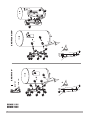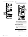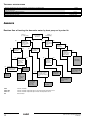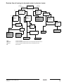
1
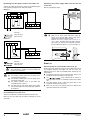
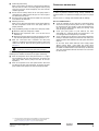
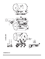
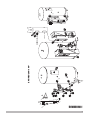
INSTALLATION AND
OPERATION MANUAL
Solar kit for air to water heat pump system
EKSOLHWAV1
1
EKHW*150*
EKHW*200*
EKHW*300*
7
7
7
7
8
8
8
8
19
89
6
6
4
A
5
3
A
2
EKHW*150*
EKHW*150*
EKHW*200*
4
7
7
7
7
19
112
8
8
8
8
6
6
A
5
3
A
2
EKHW*200+300*
10
13
12
13
1
EKSOLHWAV1
CONTENTS
Installation and
operation manual
Solar kit for air to water heat pump system
Page
Introduction ........................................................................................1
General information .....................................................................1
Scope of this manual...................................................................1
Model identification......................................................................1
General system setup and operation.................................................2
General system setup .................................................................2
Requirements and recommendations concerning
field supplied solar panels and solar pump station......................2
Accessories .......................................................................................3
Accessories supplied with the solar kit........................................3
Overview of the solar kit ....................................................................4
Main components ........................................................................4
Installation of the solar kit ..................................................................4
Selecting an installation location .................................................4
Dimensions and service space....................................................4
Installation guidelines ..................................................................5
Installing the solar kit...................................................................5
Field wiring ..................................................................................6
INTRODUCTION
General information
Thank you for purchasing this
solar kit.
EKSOLHWAV1
The
solar kit must be installed by a competent
person and be installed in compliance with the instructions in this
manual.
The solar kit is to be connected to the
domestic hot water tank.
EKHW*
The solar kit will enable you to heat up your domestic water by means
of the sun whenever the sun is available.
To get the most comfort and energy savings out of your system,
make sure to observe the section "Configuring your system" on
page 9 of this manual.
Start up ..............................................................................................8
Scope of this manual
Operating instructions........................................................................9
Configuring your system..............................................................9
This installation manual describes the procedures for installing and
operating the EKSOLHWAV1 solar kit.
Troubleshooting and servicing .........................................................11
General guidelines ....................................................................11
General symptoms ....................................................................11
Error codes................................................................................11
Disposal requirements .....................................................................11
Model identification
EK
SOL
HW
A
V1
Technical specifications ...................................................................12
Annexes ...........................................................................................12
Decision flow of heating the domestic water
by heat pump or by solar kit ......................................................12
Decision flow of heating the domestic water
by booster heater ............................................................................. 13
V1 = 1P/230 V/50 Hz
Series
Domestic hot water
Solar kit
European Kit
READ THESE INSTRUCTIONS CAREFULLY BEFORE
INSTALLATION.
PLEASE LEAVE THIS MANUAL WITH THE EKSOLHW
SOLAR KIT AFTER INSTALLATION.
IMPROPER INSTALLATION OR ATTACHMENT OF
EQUIPMENT OR ACCESSORIES COULD RESULT IN
ELECTRIC SHOCK, SHORT-CIRCUIT, LEAKS, FIRE OR
OTHER DAMAGE TO THE EQUIPMENT. BE SURE ONLY
TO USE ACCESSORIES MADE BY DAIKIN WHICH ARE
SPECIFICALLY DESIGNED FOR USE WITH THE
EQUIPMENT AND HAVE THEM INSTALLED BY A
PROFESSIONAL.
IF UNSURE OF INSTALLATION PROCEDURES OR USE,
ALWAYS CONTACT YOUR DAIKIN DEALER FOR
ADVICE AND INFORMATION.
THE UNIT DESCRIBED IN THIS MANUAL IS DESIGNED
FOR INDOOR INSTALLATION ONLY AND FOR AMBIENT
TEMPERATURES RANGING 0°C~35°C.
EKSOLHWAV1
Solar kit for air to water heat pump system
4PW41598-1
Installation and operation manual
1
GENERAL
SYSTEM SETUP AND OPERATION
Requirements and recommendations concerning field
supplied solar panels and solar pump station
General system setup
Solar panel
The solar kit is designed to transfer the heat from the solar panels to
the heat exchanger of the domestic hot water tank EKHW* and is to
be installed in the
system as shown in the
scheme below.
Appropriate selection is to be made by your solar panel supplier, in
accordance with local regulations.
Solar pump station
The solar pump station must meet following requirements:
Electrical connection
The solar pump station will have an auxiliary contact that closes
when the contact for the pump of the solar pump station is operated.
M
This contact will provide 230 V to the input of the indoor unit, and
prevent domestic water heating by the heat pump and/or booster
heater during solar heating.
For wiring examples, refer to the following drawings.
Example 1
6
7
5
1
4
L
N
R1 N
8
2
3
1
Solar panels (field supply)
2
Solar pump station (field supply)
3
Solar kit
4
Domestic hot water temperature sensor of the solar pump station
(field supply)
5
Domestic hot water temperature sensor of the indoor unit
6
Solar panel temperature sensor (field supply)
7
Solenoid 2-way valve (only for UK, refer to the EKUHW* kit)
8
Non-return valve (to be included in solar pump station or to be
installed in field piping)
Heating system.
Refer to the indoor unit installation manual.
The solar panels (1) catch the heat of the sun. When the temperature
of the glycol solution in the solar panel has become higher than the
water temperature in the domestic hot water tank, the pump of the
solar pump station (2) and the pump of the solar kit (3) start to
operate as to transfer the heat to the heat exchanger of the domestic
hot water tank, unless priority is given to the heat pump. Refer to
"Operating instructions" on page 9 (subsection: Configuring your
system).
YC Y1 Y2 Y3 Y4
P
Solar pump station
Indoor PCB: A4P
230 V
Field wiring
Solar pump station
Indoor PCB: A4P
Example 2
L
N
N
R1
YC Y1 Y2 Y3 Y4
P
Solar pump station
Indoor PCB: A4P
230 V
Field wiring
Solar pump station
Indoor PCB: A4P
If the pump station has a speed controlled pump, make
sure to disable this function so that the indoor PCB
receives 230 V at all times.
Installation and operation manual
2
EKSOLHWAV1
Solar kit for air to water heat pump system
4PW41598-1
■
Settings
■
Anti-freeze setting
Some solar pump stations have an anti-freeze function. If the
solar panel temperature becomes too low, such solar pump
stations will circulate the solar fluid as to extract heat from the
tank and to avoid freezing of the solar fluid.
Maximum solar panel temperature
If the temperature of the solar panel is above this value, the
solar pump station will stop or not resume pump operation.
This setting will have a fixed value equal to or below 110°C, or
it will be possible to put this value equal to or below 110°C.
Make sure to disable this function.
Make sure the concentration of glycol in the solar panel
is big enough as to avoid freezing of the glycol at all
times.
Putting this value to a higher value can break down
the pump of the solar pump station.
Also refer to the eye-catcher caution label that was torn up when
unpacking the installation manual.
Limiting the maximum solar panel temperature to 110°C
however, can affect efficiency of the solar panel.
But on the other hand:
■ as it is important for reliability of the pump in the solar pump
station only that temperature of the return water to that solar
pump is lower than 110°C;
Hydraulic connection
Make sure the solar pump station has non-return valves as to avoid
thermosiphon effect (migration of hot water to cold places). If the
solar pump station has no hydraulic connections included, install
them in the field piping as shown in "General system setup" on
page 2.
■ and in case the 110°C limit for the return water temperature
to the solar pump can be guaranteed by other means than by
limiting the 'Maximum solar panel temperature';
ACCESSORIES
then the value of the 'Maximum solar panel temperature' can be
set to a higher temperature.
Accessories supplied with the solar kit
Please contact your local solar panel dealer.
■
ON/OFF/AUTO
1
If the solar pump station has an ON/OFF/AUTO function, make
sure to put it on the AUTO function. This means that the pump
will switch on automatically when the solar panel temperature
rises sufficiently above the domestic hot water tank temperature
and switch off automatically when the difference between the
solar panel and the domestic hot water tank temperature
becomes too low.
3
1x
7x
4
5
6
1x
5x 2x
Maximum tank temperature
Quantity
■
2
1x
When the maximum temperature of the domestic hot water tank
is reached, the solar pump station will stop pump operation.
Do not put this value above 80°C (70°C for units installed with
the EKUHW* kit) to avoid overheating of the domestic hot water
tank and the activation of the booster heater thermal protector in
the domestic hot water tank.
1
8
7
1x
9
1x
1x
10
2x
Necessary accessory for installation
of the solar kit for each type of
domestic hot water tank
EKHW*
EKHWSU
150*
200*
300*
150*
200*
300*
Thermistor socket 1/2"
Male BSP (internal
diameter 6.1)
1
1
1
1
1
1
1
2
Connection pipe 3/4" Male
BSP x 3/4” Male BSP
1
1
1
1
—
—
—
Some solar pump stations provide the possibility to still dump
heat to the domestic hot water tank, even when the maximum
domestic hot water tank temperature is already reached. This to
reduce the solar panel temperature by circulating the solar panel
fluid and transfer the heat to the domestic hot water tank.
3
Sealing
7
6
7
7
7
6
6
4
Adaptor 3/4" Female
BSP x 3/4" Male BSP
1
—
1
1
—
—
—
5
Adaptor 3/4" Male
BSP x 3/4" Male BSP
5
5
5
5
4
5
5
If this function is present, it should be put to OFF as to avoid
thermal cut out operation of the tank.
6
PG nipple and nut
2
2
2
2
2
2
2
7
Installation manual
1
1
1
1
1
1
1
8
EKRP1HB solar/remote
alarm address card
1
1
1
1
1
1
1
9
Solar contactor assembly
K7M
1
1
1
1
1
1
1
2
2
2
2
2
2
2
NOTE
You can also change the domestic hot water
temperature setpoint on the controller of the indoor
unit. Refer to the operation manual of the indoor unit.
This temperature is sensed by the domestic hot water
temperature sensor of the indoor unit, located in the
upper thermistor holder of the domestic hot water tank.
For reasons of energy savings, it is advised to put this
temperature as low as possible without compromising
the required supply of hot water.
10 Contactor fixing screw
The maximum temperature that can be set in the
controller of the solar pump station is sensed by the
domestic hot water temperature sensor of the solar
pump station, located in the lower thermistor holder of
the domestic hot water tank.
Refer also to "Operating instructions" on page 9
(subsection: Configuring your system).
■
Minimum temperature difference between domestic hot water
tank and solar panel before starting pump operation
This minimum temperature difference will be put equal to or
above 10°C.
EKSOLHWAV1
Solar kit for air to water heat pump system
4PW41598-1
Installation and operation manual
3
OVERVIEW
INSTALLATION
OF THE SOLAR KIT
Main components
9
OF THE SOLAR KIT
Selecting an installation location
7a 7b
■
The solar kit is to be installed in a frost free indoor space,
directly connected to the domestic hot water tank.
■
Make sure the service space is available as indicated in below
drawing.
■
The space around the unit has to allow sufficient air circulation.
■
It shall be made sure that in the case of a leak, leaking water will
not cause any damage or unsafe situations.
■
Do not install or operate the unit in rooms mentioned below:
- Where corrosive gas like sulphurous gas exists: copper
tubing and brazed spots may corrode.
- Where volatile flammable gas like thinner or gasoline is used.
- Where machines generating electromagnetic waves exist:
the control system may malfunction.
- Where the air contains high levels of salt such as air near the
ocean and where voltage fluctuates a lot (e.g. in factories).
This applies also to vehicles or vessels.
9
5
3
2
4
10
1
6
Dimensions and service space
10
8
NOTE
Solar kit circulation pump
Heat exchanger
3
Inlet connection from solar pump station
4
Return connection to solar pump station
5
Inlet connection from the indoor unit
6
Return connection to the indoor unit
7a
Return connection to the 200/300 l domestic hot water tank heat
exchanger
7b
Return connection to the 150 l domestic hot water tank heat
exchanger
8
Inlet connection from the domestic hot water tank heat exchanger
9
EPP casing
10
Non-return valves
A
B
290
1
2
For installation of the solar kit to the EKHWSU150*
domestic hot water tank (UK only), the solar kit will not
fit entirely tight to the tank.
Safety functions
Thermal cut out
The solar kit is electrically connected with the thermal cut out safety
of the domestic hot water tank. (refer to "Field wiring" on page 6).
15°
When the thermal cut out safety of the domestic hot water trips, the
power supply to the pump of the solar kit is interrupted so that no
more solar heat can be transferred to the domestic hot water tank.
Solenoid 2-way valve (only for UK)
971
The thermostat will close the solenoid 2-way valve when the
temperature becomes too high (setting 79°C).
Installation and operation manual
4
A
B
EKHW*150*
EKHW*200*
EKHW*300*
EKHWSU200*
EKHWSU300*
980
400
EKHWSU150*
1010
430
EKSOLHWAV1
Solar kit for air to water heat pump system
4PW41598-1
3
Installation guidelines
■
Make sure that all the piping to the solar kit is insulated.
■
Make sure that all the piping to the solar kit is sufficiently
supported so that it will not cause any stress on the solar kit.
■
Make sure that the piping coming from outdoors to the solar kit
is put through the wall under an angle and the wall hole is
sufficiently sealed afterwards, so no water can enter the space.
1
2
3
1
Wall
2
Sealing material
3
Piping under an angle
Refer to the corresponding sub-step, depending on your tank
capacity. For UK, refer to 3.3.
■ EKHW*200/300*:
3.1 Fit the adaptor 3/4" Female BSP x 3/4" Male BSP in the flow
inlet connection of the domestic hot water tank. Refer to
"Accessories supplied with the solar kit" on page 3, part 4.
3.2 Fit the connection pipe 3/4" Male BSP x 3/4" Male BSP and
sealing in the flow inlet connection of the domestic hot water
tank. Refer to "Accessories supplied with the solar kit" on
page 3, part 2 and 3.
■ EKHW*150*: Fit the connection pipe 3/4" Male BSP x 3/4"
Male BSP in the flow inlet connection of the domestic hot
water tank. Refer to "Accessories supplied with the solar kit"
on page 3, part 2.
■ EKHWSU*
■
Make sure the piping is protected against dirt during installation.
Dirt in the piping might clog the heat exchanger of the solar
panel and reduce its performance.
3.3 Fit the adaptor 3/4" Male BSP x 3/4" Male BSP (x2) in the
solenoid 2-way valve supplied as accessory with the
EKUHW* kit. Refer to "Accessories supplied with the solar
kit" on page 3, part 5.
3.4 Fit the solenoid 2-way valve in the flow inlet connection of
the domestic hot water tank.
The valve must be mounted so that the valve head is
pointed to the front of the domestic hot water tank with the
cable entry at the bottom. Check direction of the flow arrow
cast on the solenoid valve body. Do not grip the valve head
while making and tightening up connections.
Installing the solar kit
■
At delivery, the unit should be checked and any damage should
be reported immediately to the carrier claims agent.
■
Check if all unit’s accessories are enclosed. Refer to
"Accessories supplied with the solar kit" on page 3.
■
Bring the unit as close as possible to its final installation position
in its original package in order to prevent damage during
transport.
4
4.1 Unscrew the stop 3/4" Male on the return connection to the
150 l domestic hot water tank heat exchanger. Keep sealing.
Procedure
Refer to the installation drawings. The numbers on the drawings refer
to the steps described below.
figure 1
figure 2
EKHW*150*
EKHWSU150*
EKHW*200*
4.2 Fit the stop 3/4" Male + sealing on the return connection to
the 200/300 l domestic hot water tank heat exchanger.
5
figure 3
EKHWSU200*
EKHW*300*
Locate the domestic hot water tank in a suitable position to
facilitate the installation of the solar kit. It is therefore
recommended to first read the entire installation procedure.
Refer to the installation guidelines in the installation manual of
the domestic hot water tank.
2
Fit the thermistor socket in the threaded thermistor hole for the
domestic hot water temperature sensor of the solar pump
station. (Refer to "Accessories supplied with the solar kit" on
page 3, part 1).
Fit the adaptor 3/4" Male BSP x 3/4" Male BSP in the heat
exchanger outlet connection of the domestic hot water tank.
Refer to "Accessories supplied with the solar kit" on page 3,
part 5.
For the EKHWSU150* (UK only): Fit a pipe 3/4" Male BSP x 3/4"
Male BSP in the heat exchanger outlet connection of the
domestic hot water tank (field supply, L = 50 mm).
EKHWSU300*
1
For EKHW*150* only:
6
Fit the solar kit and sealings (x2) on the heat exchanger inlet
connection and heat exchanger outlet connection of the
domestic hot water tank. Torque 5 N•m. Refer to "Accessories
supplied with the solar kit" on page 3, part 3.
7
Fit the adaptors 3/4" Male BSP x 3/4" Male BSP (x4) to the field
piping:
■ Inlet connection from
indoor unit.
■ Return connection to
indoor unit.
■ Inlet connection from solar pump station.
■ Return connection to solar pump station.
Refer to "Accessories supplied with the solar kit" on page 3,
part 5.
8
Fit the solar kit and sealings (x4) to the field piping. Torque
5 N•m. Refer to "Accessories supplied with the solar kit" on
page 3, part 3.
9
For EKHWSU* (UK only): Cut out EPP material of the EPP lid.
10
Mount the left side of the EPP casing onto the solar kit.
11
Mount the EPP lid onto the right side of the EPP casing.
12
Mount the right side of the EPP casing onto the solar kit.
Take care, that the pump cable is routed via the holes in the
bottom of the EPP casing.
Ensure that the pump cable cannot come into contact
with piping below the pump when cable is routed out.
EKSOLHWAV1
Solar kit for air to water heat pump system
4PW41598-1
Installation and operation manual
5
13
Use the screws and washers (x2) to fix the EPP casing. Screw
until tight position.
Do not switch inlet and outlet connections.
Refer to the chapter “Typical application examples” described in the
installation manual delivered with the indoor unit for details on
connecting the water circuits and the motorised 3-way valve.
To install adequate connections between the indoor
unit and the solar kit, it is important that the 3-way
valve is fitted correctly.
NOTE
Ensure that the water piping connected to the solar kit
coming from the solar panel and the indoor unit are
sufficiently supported and do not cause any stress on the
solar kit.
Description
1 ... 9
Refer to the installation manual of the indoor unit
10
Solar panel sensor cable
(Field supply with solar
pump station)
2
—
11
Domestic hot water
temperature sensor of the
solar pump station
(Field supply)
2
—
12
Operating signal cable from
solar pump station to
indoor unit
(Field supply)
2
1A
13
Power supply cable from
indoor unit to tank
(Field supply)
2
1A
14
Power supply cable from
solar kit to tank
2 + GND
1A
Installing the EKRP1HB in the indoor unit
Install the PCB delivered with the solar kit in the indoor unit.
Refer to "Accessories supplied with the solar kit" on page 3, part 8.
Charge the solar panel circuit with a glycol solution.
1
Open the EKRP1HB box.
Observe the instructions as given by your solar panel
supplier. Make sure to use non-toxic glycol.
3
2
1
3 2
1
Field wiring
■
Switch off the power supply before making any
connections.
■
All field wiring and components must be installed by a
licensed electrician and must comply with relevant
European and national regulations.
The field wiring must be carried out in accordance
with the wiring diagram and the instructions given
below.
■
Maximum
running current
Item
Charging water
Charge the water on the indoor unit and the tank (refer to the
installation manuals of the indoor unit and the domestic hot water
tank).
Required
number of
conductors
4
Overview
1
Wrapped PCB (solar/remote alarm address card)
The illustration below gives an overview of the required field wiring
between several parts of the installation. Refer also the wiring
diagram, the installation manual of the indoor unit and the domestic
hot water tank.
2
Installation manual
3
Accessories bag
4
EKRP1HB box
T
B
2 C D
4
2
Take out the PCB and unwrap it.
3
Open the accessories bag and take the connector labelled X1A.
4
Place this connector on the EKRP1HB PCB (on the connector
X1A/CN1).
5
E
M
F
M
G
X2A/CN2
6
12
1
3
13 7
14
H
I
X1A/CN1
A 9 11
J
A...I
10
K
Y1
Y2
Y3
Y4
5
Mount the plastic raisers from the accessories bag on the indoor
EKHB switch box backplate.
6
Mount the EKRP1HB PCB on the plastic raisers.
Refer to the indoor unit installation manual
J
Solar panel
K
Solar pump station
L
Solar kit
Installation and operation manual
6
YC
8 L
EKSOLHWAV1
Solar kit for air to water heat pump system
4PW41598-1
7
Mount the control cable (from the accessories bag) between
A1P: X33A (the main PCB) and A4P: X2A/CN2 (the EKRP1HB
PCB).
Installing the solar contactor assembly K7M in the
indoor unit
Refer to "Accessories supplied with the solar kit" on page 3, part 9.
1
Fix the solar contactor assembly K7M above the K7M label in
the indoor unit. Use the 2 supplied contactor fixing screws. Refer
to "Accessories supplied with the solar kit" on page 3, part 10.
OPTION EKHW*
OPTION EKHW*
OPTION EKHW*
OPTION EKHW*
X2A/CN2
X2A/CN2
OPTION EKHW*
1
2
3
thermostat
4
4a
5
6
7
2-way valve
8
9
3-way valve
10
11
12
thermal
fuse
13
14
15
15a
16
17
Q2L
18
19
20
21
SOLAR PUMP
OPTIONAL
X2M
OPTION EKHW*
OPTION EKHW*
1
2
3
thermostat
4
4a
5
6
7
2-way valve
8
9
3-way valve
10
11
12
thermal
fuse
13
14
15
15a
16
17
Q2L
18
19
20
21
SOLAR PUMP
OPTIONAL
X2M
OPTION EKHW*
2
Place the K7M connector on the X14A connector of the A1P
PCB.
3
Mount the K7M wire labelled X2M/19 on terminal block X2M at
upper position of terminal 19.
4
Pass the K7M wire labelled X2M/21 under terminal block X2M
first, and then mount that wire on terminal block X2M at lower
position of terminal 21 (at field connection side of terminal block
X2M).
Connecting the temperature sensors
1
Mount the solar panel sensor of the solar pump station in the
solar panel according to the instructions of the solar pump
station and solar panel supplier.
2
Mount the domestic hot water temperature sensor of the solar
pump station in the lower sensor holder of the domestic hot
water tank.
Insert the sensor as deep as possible in the holder and use
thermal paste.
NOTE
EKSOLHWAV1
Solar kit for air to water heat pump system
4PW41598-1
■
The domestic hot water temperature sensor of the
indoor unit is mounted in the upper sensor holder
of the domestic hot water tank.
■
The distance between the thermistor cables and
power supply cable must always be at least 5 cm
to prevent electromagnetic interference on the
thermistor cables.
Installation and operation manual
7
Connecting the solar pump station to the indoor unit
Connect the indoor unit terminals as shown on the following figures
to the (auxiliary) contact from the solar pump station.
Connecting the power supply cable from the solar kit
to the tank
Refer to wiring diagram sticker.
Example 1
L
N
R1 N
YC Y1 Y2 Y3 Y4
P
Solar pump station
Indoor PCB: A4P
230 V
Field wiring
Solar pump station
Indoor PCB: A4P
■
Make sure to connect the earth conductor.
■
Make sure to ensure strain relief of the cables by
correct use of the PG nipples and PG nuts (to be
mounted on the domestic hot water tank).
Refer to "Accessories supplied with the solar kit" on
page 3, part 6. Positions where PG nipples and PG
nuts need to be screwed in the domestic hot water
tank are indicated on figures 1, 2 and 3 as actions 14.
Example 2
L
N
N
R1
2x
P
Solar pump station
14
YC Y1 Y2 Y3 Y4
Indoor PCB: A4P
230 V
Field wiring
Solar pump station
START
UP
Indoor PCB: A4P
Commissioning the system before initial start up
If the pump station has a speed controlled pump, make
sure to disable this function so that the indoor PCB
receives 230 V at all times.
Make sure that:
Besides the checks before initial start up of the indoor unit (refer to
the installation manual of the indoor unit) you must check the
following items on the solar kit installation before switching on the
circuit breaker:
■
the (auxiliary) contact closes when the pump of the
solar pump station operates;
the (auxiliary) contact opens when the pump of the
solar pump station stops;
The domestic hot water tank is filled with water. Refer to the
installation manual of the domestic hot water tank.
■
The
circuit, connected to the solar kit is
filled with water. Refer to the installation manual of the indoor
unit.
■
the contacts provides 230 V to the indoor unit
connection when it is closed;
■
The solar collector circuit is filled with glycol. Refer to the
installation manual of the solar circuit.
■
the cable from the solar pump station to the indoor
unit is protected by a fuse in the solar pump station or
by a field fuse.
■
Make sure the solar kit is properly fixed to the domestic hot
water tank and that there are no leaks.
■
■
Connecting the power supply cable from the indoor unit
to the domestic hot water tank
Connect the indoor unit terminals to the domestic hot water tank.
Make sure to fix the cables with the cable tie mountings to ensure
strain relief.
Installation and operation manual
8
EKSOLHWAV1
Solar kit for air to water heat pump system
4PW41598-1
■
Field wiring and earthing
Make sure the pump of the solar kit is connected to the domestic
hot water tank as shown in the wiring diagram and the pump
earth wires have been connected properly. The earth terminals
should be tightened.
OPERATING
■
Ensure that the auxiliary contact of the solar pump station is
connected to the indoor unit and will give 230 V to the input of
the indoor unit when closed.
In order to guarantee maximum energy savings combined with
maximum comfort, it is important to configure your system in a proper
way.
■
Ensure the power supply cable from the indoor unit is connected
to the domestic hot water tank.
For this reason, it is strongly recommended to do the following:
■
Mounting of sensors
Make sure the solar panel temperature sensor and the domestic
hot water temperature sensor of the solar pump station are
properly mounted.
Use of schedule timers
■
■ Maximum tank temperature: ≤80°C (70°C for units with an
EKUHW* kit)
■ Minimum temperature difference between domestic hot water
tank and solar panel before starting pump operation: ≥10°C
■
Configuring your system
■
Check the orientation of your solar panel, and find out during
what time of the day the intensity of the sun on it is expected to
be strong and weak. For example, a solar panel oriented to the
east will receive strong intensity during the morning, weak
intensity during the afternoon.
■
Check your usual pattern of peak domestic hot water
consumption. E.g. showering during the morning from 7 to 9
a.m. and again in the evening from 5 p.m. onwards.
■
Set the schedule timer for ‘domestic water heating’ and ‘booster
heating’ as to disable heating of the domestic water tank by the
indoor unit before solar radiation on the solar panel can become
intensive.
Verify that following settings are made on the solar pump station:
■ Maximum solar panel temperature: ≤110°C
Make sure a non-return valve is included in the solar pump
station or is installed in the connection line from the solar pump
station to the solar kit. Refer also to the general system set-up
(on page 2).
Absence of this valve will cause thermal losses and
could cause freezing of the plate heat exchanger.
Checklist for proper functioning
INSTRUCTIONS
On the other hand, enable 'domestic water heating' and/or
'booster heating' about 1 hour before you usually expect
domestic hot water consumption or during night time. In this way,
the indoor unit and/or booster heater will heat up the domestic
water tank and guarantee domestic hot water in the event there
has been no sun.
Following items should be checked to assure proper functioning:
■
When the temperature of the solar panel becomes 10°C higher
than the domestic hot water tank temperature, the pump of the
solar pump station and the pump of the solar kit will start
operation.(1)
■
When the temperature of the solar panel becomes lower than
the domestic hot water tank temperature, the pump of the solar
pump station and the pump of the solar kit will stop operation.
(1) Unless the domestic water heating mode is enabled, the solar priority parameter
= 1 and the heat pump is heating the domestic water tank at that moment.
Refer to "Configuring your system" on page 9 for more information.
EKSOLHWAV1
Solar kit for air to water heat pump system
4PW41598-1
Installation and operation manual
9
Example
Your domestic hot water consumption pattern is from 7 a.m. to 9 a.m. in the morning and from 5 p.m. till 11 p.m. in the evening.
Since the solar panel is oriented towards the south-east, the radiation can be intensive on the solar panel from 8 a.m to 6 p.m.
Domestic hot water
consumption pattern
Expected
Not expected
Solar radiation on the
solar panel
Strong
Weak
Recommended setting of schedule timers
Domestic water
heating/booster heating
Enable
Disable
Hour
0
1
2
3
4
5
If the domestic hot water tank has not been heated enough by the
sun during the day, or a lot of warm water was consumed the evening
before, the domestic hot water tank must be heated up during the
night time by the indoor unit, so that in the morning domestic hot
water is available for consumption. For this reason, in the example
above, domestic water heating is enabled during the night, until
consumption of warm water is expected to start.
6
7
8
9 10 11 12 13 14 15 16 17 18 19 20 21 22 23 24
Setting of the solar priority parameter
Simultaneous water heating by the sun and water heating by the heat
pump is not possible.
By default, heating of the tank by the heat pump has priority over
heating by the sun.
In the morning, the domestic water heating/booster heating is
disabled. In this way, the domestic hot water tank is not reheated
after or during consumption of warm water and the sun will get the
chance to reheat the water as much as possible.
This means that, whenever there is a request of the domestic hot
water thermostat and domestic water heating is enabled (by the
schedule timer or domestic water heating ON/OFF button, refer to the
operation manual of the indoor unit), heating will be done by the heat
pump. In case solar heating is busy, solar heating will be stopped.
Since domestic hot water consumption is expected again from 5 p.m.
onwards, the domestic water heating and/or booster heating is
enabled again 1 hour before, from 4 p.m. onwards. This will
guarantee, in the case of absence of sun during the day, maximum
warm water capacity by 5 p.m.
This is to avoid shortage of domestic hot water in case the solar
radiation is very weak, or solar radiation only became high shortly
before domestic hot water demand is expected (e.g. on a cloudy
day).
NOTE
To set schedule timers, refer to the operation manual
of the indoor unit.
Setting of domestic hot water tank temperature
The domestic hot water tank has 2 temperature sensors.
The upper temperature sensor is the thermostat sensor of your
indoor unit. This temperature can be set on your indoor unit (refer to
the operation manual of the indoor unit). It is advised to set this
temperature as low as possible. Start with a low temperature, e.g.
48°C. If with this temperature you face shortage of warm water during
normal tapping patterns, increase gradually until you find the
temperature of warm water that covers your daily demand.
NOTE
In order to change this, put the field parameter [C-00] to 0. Refer to
the installation manual of the indoor unit, paragraph "Field settings"
to find out how to access and change field parameters. [C-00] put to
0 means solar priority, [C-01] put to 1 means heat pump priority.
NOTE
With above settings, the heating of the water by heat pump/booster
heater will be limited to the minimum required, and solar heat will be
stocked in the domestic hot water tank to the maximum.
Installation and operation manual
Be aware that setting this parameter to 0 might cause
insufficient warm water at the time of domestic hot
water demand during days with weak solar intensity.
If you are not sure about the availability of hot water,
check the domestic hot water temperature on the
controller (see operation manual of the indoor unit) and
if too low, push the 'booster domestic hot water' button.
This will trigger domestic water heating by the heat
pump immediately.
Refer to the operation manual of the indoor unit to
change the domestic hot water temperature setting.
The lower temperature sensor is the thermostat sensor of the solar
pump station. This temperature can be set on the solar pump station.
Put this temperature as high as possible but not higher than 80°C (or
70°C for units installed with the EKUHW* kit) as otherwise the
thermal protection in the tank might trip.
10
This default setting can be changed, so that at all times, when solar
heat becomes available, domestic water heating by the heat pump
will be (if busy) interrupted and taken over by the sun.
NOTE
The booster heater in the domestic hot water tank can
work independent from the solar heating or domestic
water heating by the heat pump.
For a detailed decision flow on domestic water heating
by solar kit or by heat pump, and/or booster heater,
refer to the annexes "Decision flow of heating the
domestic water by heat pump or by solar kit" on
page 12 and "Decision flow of heating the domestic
water by booster heater" on page 13.
EKSOLHWAV1
Solar kit for air to water heat pump system
4PW41598-1
TROUBLESHOOTING
AND SERVICING
Error codes
This section provides useful information for diagnosing and
correcting certain troubles which may occur with the unit.
When a safety device is activated, the user interface LED will be
flashing, and an error code will be displayed.
General guidelines
Following error codes might be related to a malfunction of your solar
system. First, check also the corrective actions as mentioned in the
installation manual.
Before starting the troubleshooting procedure, carry out a thorough
visual inspection of the unit and look for obvious defects such as
loose connections or defective wiring.
Before contacting your local Daikin dealer, read this chapter carefully,
it will save you time and money.
When carrying out an inspection on the switch box of the
unit, always make sure the main switch of the unit is
switched off.
When a safety device was activated, stop the unit and find out why
the safety device was activated before resetting it. Under no
circumstances safety devices may be bridged or changed to a value
other than the factory setting. If the cause of the problem cannot be
found, call your local dealer.
Reset the safety by turning the unit OFF and back ON.
Instruction to turn the unit OFF
User interface mode
(heating/cooling =)
Domestic water
heating mode (w)
Push the
y button
Push the
v button
ON
ON
1 time
1 time
ON
OFF
1 time
—
OFF
ON
—
1 time
OFF
OFF
—
—
In case this procedure for resetting the safety is not successful,
contact your local dealer.
Error
code
Failure cause
Corrective action
Outlet water temperature of
indoor unit too high (>65°C)
Check the 3-way valve and its
wiring:
• 3-way valve is broken or
wrongly connected and
remains in the 'domestic hot
water' position during
operation of the solar kit.
• One of the non-return valves
in the solar kit is broken.
Check the non-return valves.
Booster heater thermal protector
is open
The maximum allowed
temperature setting on the solar
pump station is set too high.
(should be set below 80°C).
Reset the booster heater
thermal protector on the
domestic hot water tank.
BH
General symptoms
Symptom 1: The pump of the solar pump station starts
operation, but the pump of the solar kit is not working.
POSSIBLE CAUSE
1
2
3
The tank has reached its
maximum allowed
temperature (tank
temperature reading on
the indoor unit display
≥80°C)
The auxiliary contact
from the solar pump
station to the indoor unit
is not properly wired
CORRECTIVE ACTION
AA
Refer to "Maximum tank temperature" on
page 3.
Check the wiring. Make sure that when the
solar pump station pump is operating, the
indoor connection receives 230 V.
(If present, disable the variable speed
function of the solar pump station)
The pump of the solar kit
is not properly wired to
the indoor unit through
the tank
Check the wiring.
4
The priority for domestic
water heating is given to
the heat pump
Refer to "Setting of the solar priority
parameter" on page 10.
5
The thermal cut out of the
tank has operated
Refer to error code AA in "Error codes" on
page 11.
Symptom 2: There is a lot of sun intensity but the solar pump
station and solar kit pumps do not start.
POSSIBLE CAUSE
1
The maximum
temperature of the
domestic hot water tank
is reached
2
The outdoor unit is
heating up the domestic
water tank, since the
priority for domestic
water heating is given to
the heat pump
CORRECTIVE ACTION
Check the domestic hot water temperature
on the controller of the indoor unit (refer to
the operation manual of the indoor unit) and
check the maximum temperature setting on
your solar pump station.
REQUIREMENTS
Dismantling of the unit, treatment of the refrigerant, of oil and of other
parts must be done in accordance with relevant local and national
legislation.
Your product is marked with this symbol. This means
that electrical and electronic products shall not be
mixed with unsorted household waste.
Do not try to dismantle the system yourself: the dismantling of the
system, treatment of the refrigerant, of oil and other parts must be
done by a qualified installer in accordance with relevant local and
national legislation.
Units must be treated at a specialized treatment facility for re-use,
recycling and recovery. By ensuring this product is disposed off
correctly, you will help to prevent potential negative consequences for
the environment and human health. Please contact the installer or
local authority for more information.
Refer to "Setting of the solar priority
parameter" on page 10.
EKSOLHWAV1
Solar kit for air to water heat pump system
4PW41598-1
DISPOSAL
Installation and operation manual
11
TECHNICAL
SPECIFICATIONS
• Maximum operating pressure of the connections to and from the solar pump station
• Maximum operating pressure of the connections to and from the indoor unit and connections to and from the domestic hot water
tank heat exchanger
• Minimum/maximum ambient temperature
• Minimum/maximum fluid temperature
• Heat transfer liquid (solar side)
2.5 MPa
0.3 MPa
1/35°C
1/110°C
propylene glycol
ANNEXES
Decision flow of heating the domestic water by heat pump or by solar kit
Setting = 0
Setting = 1
(no solar priority)
Yes
No
Solar energy
available (Solar
panel T > DHW T
SPS +10°C)
DHW T I/U ≤
heat pump ON
temperature
Yes
No
Solar priority
parameter
No
(solar priority)
Yes
Solar energy
available
(Solar panel T
> DHW T SPS
+10°C)
No
DHW T I/U ≤ heat
pump ON
temperature
DHW T I/U ≤
heat pump ON
temperature
Yes
No
DHW heating
enabled (by
schedule timer or
domestic water
heating button)
Yes
Yes
No
No
No
DHW heating
enabled (by
schedule timer
or domestic
water heating
button)
DHW T SPS >
maximum
domestic hot water
tank temperature
Yes
Yes
No
DHW heating
by heat pump
DHW
heating by
heat pump
No
DHW
heating by
solar kit
DHW T SPS >
maximum
domestic hot
water tank
temperature
Yes
Tank on
maximum
allowed
temperature: no
more heating
allowed
DHW heating enabled
(by schedule timer or
domestic water heating
button)
DHW heating
by solar kit
Yes
DHW heating
only possible by
booster heater.
Refer to BH
decision flow
Domestic Hot Water
DHW T SPS
Domestic Hot Water Temperature by the Solar Pump Station temperature sensor
DHW T I/U
Domestic Hot Water Temperature by the Indoor Unit temperature sensor
BH
Booster Heater
12
Tank on maximum
allowed temperature:
no more heating
allowed
DHW heating by
heat pump
DHW
Installation and operation manual
DHW heating only
possible by booster
heater. Refer to BH
decision flow.
EKSOLHWAV1
Solar kit for air to water heat pump system
4PW41598-1
Decision flow of heating the domestic water by booster heater
Setting = 1
(no solar priority)
Yes
Solar energy
available (Solar
panel T > DHW T
SPS +10°C)
Yes
No
Setting = 0
(solar priority)
Solar priority
parameter
Yes
No
Solar energy
available
(Solar panel T
> DHW T SPS
+10°C)
No
DHW T I/U ≤ BH
ON temperature
No
DHW T I/U ≤
BH ON
temperature
Yes
No
DHW T I/U ≤
BH ON
temperature
No BH operation
(solar kit will operate
if maximum
temperature not
reached yet)
BH operation
enabled (by
schedule timer)
Yes
Yes
No
BH operation
enabled (by
schedule timer)
No
No
Yes
No
Yes
Yes
BH delay
time
finished
BH operation
Yes
No BH operation
(solar kit will
operate if
maximum
temperature not
reached yet)
BH operation
enabled (by
schedule
timer)
BH delay time
finished
No
BH delay time finished
BH operation
together with
solar kit
No BH
operation
Yes
No BH operation
BH operation
DHW
Domestic Hot Water
DHW T SPS
Domestic Hot Water Temperature by the Solar Pump Station temperature sensor
DHW T I/U
Domestic Hot Water Temperature by the Indoor Unit temperature sensor
BH
Booster Heater
EKSOLHWAV1
Solar kit for air to water heat pump system
4PW41598-1
Installation and operation manual
13
2
EKHWSU150*
8
8
8
8
89
42
7
7
7
7
6
A
6
4
EKHWSU150*
EKHWSU200+300*
4
5
3
A
2
EKHWSU150*
10
11
EKHWSU150*
9
EKHWSU200+300*
12
13
13
2
19
112
7
7
7
7
A
8
8
8
8
6
6
5
3
A
2
EKHWSU200+300*
10
11
EKHWSU150*
EKHWSU200+300*
9
12
13
13
3
EKHWSU200*
EKHWSU300*
3
4PW41598-1
Copyright © Daikin