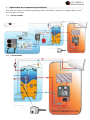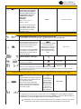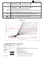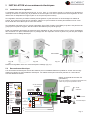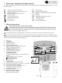
1
NOTICE DE MONTAGE REGULATION PAR ZONE NOT0004, notice kit régulation par zone rev H CLIMATICONTROL HC INSTALLATION AND USER GUIDE CLIMATIC CONTROL WITH HEAT&COOL FUNCTION ------------------------------------------------- GUIDE D’UTILISATION ET MISE EN SERVICE REGULATION CLIMATIQUE AVEC FONCTION CHUAD / FROID --------------------------------------- 1 1 Implantation des composants hydrauliques Vous trouverez ci-joint un schéma d’implantation préconisé par SDEEC, à noter que la régulation décrite ci-après est conçu pour ce schéma. 1.1 Circuit complet En cours 1.2 Circuit détaillé En cours 3 Notice Kit Régulation par zones –version G 2.2 Implantation de votre STATION monobloc Votre station est composée : 1 vanne thermomètre eau froide 1 vanne thermomètre eau chaude 1 circulateur 1 vanne 3 voies 4 raccords femelle 1 pouce l’ensemble est isolé dans une coque polystyrène emboîtable 2.2.1 Implantation physique la station doit être fixée sur une surface verticale plane et adaptée pour supporter le poids de l’ensemble. Ci contre un exemple : 2.2.2 Raccordement électrique Mis à part le moteur de la V3V (chapitre suivant), seul le circulateur est à brancher directement sur l’alimentation (en 220V), il convient de rejoindre le disjoncteur prévu pour ce kit. A noter que le circulateur est toujours en fonctionnement pour assurer une circulation constante dans la zone, dissipant ainsi la chaleur produite. 2.2.3 Raccordement hydraulique Avec la station monobloc, rien de plus simple ! vous n’avez plus qu’a suivre le schéma du §1.2 et raccorder vos 4 entrée/sortie d’eau. Veillez à assurer une bonne étanchéité des raccords. 5 Notice Kit Régulation par zones –version G 2.3 Implantation du moteur de la vanne 3 voies Votre station est livrée sans moteur de V3V 0/10Vpré-monté, il convient donc de faire le montage mécanique et électrique de ce moteur qui vous a été livré avec le kit complet (réf : KH06_ZONES_STA). 2.3.1 Montage mécanique Mettre l’adaptateur adéquate (voir éclaté ci-après) et fixer l’ensemble. 2.3.2 Raccordement électrique Le boîtier de commande (décrit dans le §2.1) est prévu pour alimenter un moteur de vanne 3 voies proportionnelle en 24V + 1 signal 0/10V. Le raccordement électrique dépend du modèle choisi et les indications portées sur le schéma électrique 0103295 sont adapté au modèle proposé dans le kit complet. ci-contre le câblage du modèle « Promix AVC », veuillez vous assurer que le produit décrit ci avant est conforme à votre produit (SDEEC se réserve le droit de faire évoluer ces produits), dans le cas contraire contactez notre service Technique. 3 3.1 Principe de fonctionnement Fonctionnement nominal Chaque zone est régulée indépendamment suivant une température de consigne d’eau pré-réglée, suivant la demande détectée par le régulateur la vanne 3 voies s’ouvre plus ou moins pour distribuer l’eau chaude produite dans le circuit primaire. Donc il y a autant de « mélange » que de zone à gérer (plancher-chauffant, ventilo-convecteur, radiateurs etc…). De son côté la PAC produit de l’eau à température de la zone la plus chaude. 4 4.1 Modification des paramètres Les réglages SDEEC 6 Notice Kit Régulation par zones –version G F MANUEL D’INSTALLATION ET D’UTILISATION Climatic Control-HC, Gestion température d’eau pour installation réversible. IMPORTANT! Il est recommandé que l’installateur et l’utilisateur prenne connaissance de l’intégralité de la notice, avant de procéder à l’installation du matériel. Le module de régulation Climatic Control-HC doit être installé et raccordé uniquement par un installateur qualifié; la garantie pourrait devenir obsolète en cas non respect de cette directive. Le constructeur ne pourra être tenu pour responsable d’une mauvaise utilisation du module. “Pour des raisons de sécurité”, les modifications du module ne sont pas autorisées et les réparations devront être faites en accord avec le constructeur. La plage de température et l’équipement interne dépendent du module. Ce prospectus doit faire parti de l’emballage. Sujet à modification sans avis préalable! Application ................................................................................................................................................................21 Références, Symboles et Abréviations ..................................................................................................................22 INSTRUCTIONS DE SECURITE................................................................................................................................22 Affichage....................................................................................................................................................................22 INSTALLATION et raccordement electriques ........................................................................................................23 INSTALLATION DE LA REGULATION 23 RACCORDEMENT ELECTRIQUE 23 THERMOSTAT D’AMBIANCE – DIRECT PLUG IN 24 Circuit avec vanne mélangeuse, thermostat de type filaire ................................................................................................ 24 Circuit direct (Sans vanne mélangeuse), thermostat de type filaire ................................................................................... 24 Circuit à vanne mélangeuse, thermostat d’ambiance RF “trF1” ....................................................................................... 25 Circuit à vanne mélangeuse, thermostat hygraostat d’ambiance RF “trF1” ..................................................................... 25 Circuit direct (sans vanne mélangeuse), thermostat d’ambiance RF “trF2” ..................................................................... 25 FONCTIONS DES ENTREES LOGIQUE (IN1 & IN2) 26 Entrée 1 “In1” .................................................................................................................................................................... 26 Entrée 2 “In2” .................................................................................................................................................................... 26 DESCRIPTION DES MODES DE FONCTIONNEMENT ...........................................................................................27 TYPES DE FONCTIONNEMENT 27 MENUS DE PROGRAMMATION 28 MENU INSTALLATION ..............................................................................................................................................32 PARAMETRES D’INSTALLATION 32 COURBE DE REGULATION 37 CARACTERISTIQUES TECHNIQUES ......................................................................................................................37 DEFAUTS ET SOLUTIONS .......................................................................................................................................38 1 Application Le module de régulation hydraulique Climatic Control-HC est utilisé pour la régulation à température variable des systèmes basses températures (ex: plancher chauffant et rafraichissant, murs chauffants, Ventilo convecteur) ainsi que pour la régulation à haute température des systèmes de chauffages par radiateurs. La température de départ est régulée en fonction de la température extérieure grâce à une courbe de chauffe ajustable. La pente de la courbe sera dépendante des conditions extérieures et des émetteurs. Grâce à ce module, les réglages pourront être adaptés, pour des résidences, des appartements ou des bureaux. La régulation est munie d’une horloge de programmation hebdomadaire, avec 9 pré programmes et 4 programmes utilisateur personnalisable. La régulation peut être associée à un thermostat d’ambiance. Ce thermostat pourra être de type filaire ou Radio Fréquence. L’utilisation d’un thermostat permet d’ajuster le niveau de confort à une pièce de référence dans l’installation (Des précautions seront à prendre sur plancher chauffant multizones). Le module de régulation a été étudié pour un fonctionnement dans un environnement sec, souvent ce module sera installé en chaufferie. Il est recommandé d’installer ce module selon les règles de l’art le tout en respectant les législations en vigueur. 21 F 6 DESCRIPTION DES MODES DE FONCTIONNEMENT 6.1 Types de fonctionnement Utiliser les touches de navigation (◄) et (►) pour déplacer le cadre de sélection de la barre de menu. Mode CONFORT Fonctionnement en mode Confort pour une durée illimité. La régulation fonctionnera constamment, elle ajustera la température de départ d’eau en fonction de la température extérieur et de la courbe de régulation choisie. La température de départ d’eau ainsi que la température extérieure sont affichées respectivement en position 5 et 13 sur l’afficheur. (les valeurs affichées sont moyennée). En appuyant sur (OK) vous pourrez visualiser la température d’eau théorique (fonction de la courbe) en 5, ainsi que la valeur du décalage de courbe ajoutée à cette température en 13. (Valeur usine 00.0 = pas de décalage). Vous pouvez régler cet offset avec les touches (+) or (-) La nouvelle température de départ sera alors affichée (valeur théorique plus valeur du décalage). Le symbole est affiché pour vous indiquer qu’il y a un décalage de réglé. Fonctionnement du circulateur : Le circulateur sera arrêté si la vanne mélangeuse est fermée depuis plus de 30 minutes. Se serait le cas si la température de départ d’eau dépassait la valeur théorique calculée (si toutes les zones du circuit sont fermées dans le cas ou une régulation de plancher chauffant est installée par exemple), La même chose pourrait arrivée si la température extérieure augmentait suffisamment (journée ensoleillée…). Dans tout les cas le circulateur se remettra en route immédiatement si la température de départ d’eau passe en dessous de la valeur théorique calculée. Par soucis de gain d’énergie le circulateur devrait être contrôlé par un système de «logique de pompe ». Ces systèmes sont généralement utilisés avec les régulations de plancher chauffant pièces par pièces agissant sur des têtes thermostatiques montées sur le collecteur. Dans ce cas là le circulateur est mit en route si au moins une zone du circuit est ouverte (en demande de chaud ou de froid). Si la chaudière ou le générateur de chaleur CH utilisé dans l’installation est en mode « ECO ou réduction» et que la température de départ d’eau demandée par la régulation est supérieure à celle fournie par la chaudière CH, la vanne mélangeuse va s’ouvrir à fond pour faire rentrer un maximum d’eau chaude dans le circuit plancher ou radiateur. Le circulateur pourra alors être coupé par le limiteur de température TC (si installé) quand la Chaudière CH se remettra en mode normal. Le circulateur se remettra en route quand le thermostat aura détecté une baisse suffisante de la température. (passage en dessous de la température réglée sur le TC). Si le TC est de type sécurité à réarmement veillez à ne pas le régler trop bas afin d’éviter ce type de problème. Problème et solutions: Le limiteur de température ne devrait pas être installé trop prêt de la régulation pour éviter ce type de problème. En cas de problème vous pouvez augmenter momentanément la température de consigne de votre TC afin que le circulateur puisse redémarrer et faire baisser la température. Ou enlever le limiteur TC du tuyau et le remettre ensuite au bout de quelque minutes. Mode AUTOMATIQUE Ce mode vous permet de gérer vos abaissements de température de départ d’eau en accordance avec le programme choisi (program pré établi ou programme user). Se référer à la section 6.2 pour plus d’information sur la partie programmation. Le principe de fonctionnement du circulateur est le même que décrit dans le Mode CONFORT. Mode ECO Fonctionnement en mode ECO pour une durée illimité. La régulation fonctionnera constamment, elle ajustera la température de départ d’eau en fonction de la température extérieur et de la courbe de régulation choisie, le tout en tenant compte de l’abaissement. La température de départ d’eau ainsi que la température extérieure sont affichées respectivement en position 5 et 13 sur l’afficheur. (les valeurs affichées sont moyennée). En appuyant sur (OK) vous pourrez vi27 F sualiser la température d’eau théorique (fonction de la courbe) en 5, ainsi que la valeur du décalage de courbe ajoutée à cette température en 13. (Valeur usine -10.0 = pas de décalage). Vous pouvez régler cet offset avec les touches (+) or (-) La nouvelle température de départ sera alors affichée (valeur théorique plus valeur du décalage). Le symbole est affiché pour vous indiquer qu’il y a un décalage de réglé. Le principe de fonctionnement du circulateur est le même que décrit dans le Mode CONFORT. MODE VACANCE/ABSENCE Période de fonctionnement à durée limitée du mode ECO . Vous pouvez régler la durée de la période de 1H à 44 jours (en heure “H” de 1H à 24h et après en jours “d” de 1 à 44 jours). Quand la période sera terminée votre système retournera en mode de fonctionnement AUTO. Régler la durée de votre absence avec les touches (+) et (-) = 1 heure; = 1 jour Exemple: et clignotent. Le décompte de la durée est alors affiché en 13. Les symboles Vous pouvez interrompre à tout moment cette période en réglant la valeur affichée en 13 sur “ de la touche (-). ” à l’aide Mode ARRET Utilisez ce mode pour éteindre votre installation. La version du logiciel est affichée pendant 5 secondes avant l’extinction de l’afficheur. Appuyez sur une touche pour rallumer votre système. Afin de protéger les composants hydrauliques de votre installation ce mode préservera une température d’eau de 10°C à l’intérieure des canalisations de chauffage (circuit à vanne mélangeuse uniquement). Cette température ne pourra être maintenue que si la source de chaleur CH est en service. Mode Chauffage / Rafraichissement Utilisez ce mode pour changer le mode de fonctionnement de votre installation. Passer du mode chauffage au mode rafraichissement. Ce menu ne sera pas disponible si un thermostat Hygrostat RF est connecté à l’installation ou si une entrée logique est utilisée pour la commutation du mode de fonctionnement. ATTENTION: En cas d’installation avec une P.A.C. non couplée avec votre régulation ClimaticControl-HC assurez-vous du bon de fonctionnement de celle-ci avant de changer celui de la régulation. 6.2 Menus de programmation MODE REGLAGE DE L’HORLOGE Utiliser ce mode pour ajuster l’heure et le jour de la semaine. Une fois le mode horloge choisi appuyer sur (OK) pour accéder aux réglages des : Régler les minutes avec (+) ou (-), valider avec (OK). Régler les heures avec (+) ou (-), valider avec (OK). Régler le jour de la semaine avec (+) ou (-), valider avec (OK). 28 F MODE PROGRAMMATION Utiliser ce menu pour créer ou choisir votre programme d’abaissement de température de départ d’eau. (basculement entre les températures de CONFORT et ECO). Le programme choisi sera suivi en mode AUTOMATIQUE « ». Vous avez le choix entre 9 programmes pré établi « P1 à P9 » ( 6.2.1.) ou 4 programmes configurables « U1 à U4 ». Tout d’abord placer le curseur de mode sur Programme avec les touches de navigations (◄) et (►). Le numéro du programme courant s’affiche en 5, appuyer sur la touche (OK), le numéro de programme clignote vous pouvez maintenant en choisir un autre avec les touches (+) ou (-). Valider votre choix avec (OK). * Vous pouvez parcourir les jours de la semaine avec les touches (◄) et (►).afin de visualiser le programme. Programmes Utilisateur (U1 – U4) Si vous choisissez un des 4 programmes utilisateurs vous serez invité à le créer en appuyant sur la touche (OK). L’écran suivant apparait : Jour courant du programme. Heure courante du programme. La touche (+) permet de sélectionner une température de CONFORT La touche (-) permet de sélectionner une température ECO à la position du curseur. à la position du curseur. Vous pouvez utiliser les touches (◄) & (►) pour déplacez le curseur clignotant dans la journée pour modifiez ou corrigez le programme avec (+) ou (-). Une fois le programme de la journée 1 terminée vous serez invité à programmer la journée 2. Vous pouvez aussi valider une journée en appuyant sur la touche (OK), le jour suivant sera alors affiché. La programmation se termine en validant le jour 7. Replacez maintenant le curseur de mode sur pour que votre programma soit suivi. * Durant la programmation, si aucune touche n’est pressée durant 20 secondes, la régulation revient à l’écran d’accueil du mode Programme si vous attendez encore 15 secondes elle reviendra sur le mode AUTOMATIQUE et suivra le dernier programme édité. Programmes usine Pré établi (P1 – P9) Si vous choisissez un des 9 programmes pré établis usine, vous pourrez parcourir les jours de la semaine avec les touches (◄) & (►). Confirmer votre choix en appuyant sur la touche (ОК), placer alors le curseur de mode sur AUTOMATIQUE . * Durant la visualisation du programme, si aucune touche n’est pressée durant 20 secondes, la régulation revient à l’écran d’accueil du mode Programme si vous attendez encore 15 secondes elle reviendra sur le mode AUTOMATIQUE et suivra le dernier programme édité. 29 F Description des programmes usine P1 à P9 P1 P2 P3 P4 P5 Matin, Soir & Week-end Matin, Midi, Soir & Week-end Jour & Week-end Soir & Week-end Matin, Soir (Salle de bain) P6 P7 P8 P9 30 Matin, Après-midi & Week-end 7h - 19h (Bureau) 8h - 19h , Samedi (Commerce) Week-end (Maison secondaire) F Les programmes sont suivis uniquement dans le mode AUTO . Le programme ne fait qu’osciller entre le mode CONFORT et ECO . Du fait si des décalages de courbe ont été rentrés dans les modes CONFORT et ECO ils seront aussi pris en compte en mode AUTO. 31 F 7 MENU INSTALLATION Paramètres d’installation 7.1 - Pour accéder au menu d’installation placer le curseur de mode sur le mode , presser alors la touche (ОК) pendant 10 secondes. Le symbole suivant doit apparaitre en haut à gauche de l’écran avec le premier paramètre de la liste. - Déplacer vous dans le menu paramètre avec les touches (◄) & (►). Appuyer alors sur la touche (ОК) pour modifier le paramètre affiché. Si la valeur du paramètre clignote vous pourrez la modifier avec les touches (+) et (-). Valider alors votre choix (ОК). - Pour sortir du menu installation, allez sur le paramètre “End” avec la touche (►) et presser sur la touche (OK). * si aucune touches n’est pressées pendant 4 minutes la régulation sera repositionnera sur le mode AUTO . Menu paramètres Affichage Description du paramètre Valeur usine Possibilité Paramètres Chauffage 0.7 1 Courbe de régulation Voir abaque de température (fig. 10) 55 °C (Lo+5°C) – 100 °C 2 Valeur maximale de la température d’eau envoyée dans le circuit. 10 °C 0 – (Hi-1°C) 3 Valeur minimale de la température d’eau envoyée dans le circuit. 0à5 Paramètres Climatisation 0.7 1 Courbe de régulation Voir abaque de température (fig. 10) Valeur maximale de la température d’eau envoyée dans le circuit. 55 °C (Lo+5°C) – 100 °C 2 10 °C 0 – (Hi-1°C) 3 Valeur minimale de la température d’eau envoyée dans le circuit. ___ Inst 0à5 Type d’installation 4 Act: Installation réversible avec vanne d’inversion. La sortie “Froid” pilote une vanne 3 voies, qui dirigera vers le circuit l’eau froide ou l’eau chaude. La sortie “Chaud” gérera la chaudière. Act, SEP Reportez vous au shéma d’installation pour plus d’information. SEP: Installation avec élément séparés (Chaudière & groupe froid). Une sortie pour chaque élément. Les deux possibilités suivante sont faites les groupes Hydrauliques « Kit 2 Zones » ou pour tout autre type d’installation avec deux circulateurs. Le circuit plancher sera gérzer par le circulateur 1. Le circuit radiateur sera géré par le circulateur 2 (connecté sur la sortie “Froid”. 2P.1: Installation réversible avec plancher chauffant/rafraichissant et Radiateur. 2P.2: Installation réversible avec plancher chauffant/rafraichissant et Ventilo convecteur. 32 SEP 2P.1 Le circulateur 2 sera coupé en mode rafraichissement. (pas de circulation d’eau froide dans le circuit radiateur) 2P.2 Le circulateur 2 fonctionnera en accordance avec son thermostat. vos réglages F ___ th Type de thermostat installé: 5 No: Installation sans thermostat Yes: Thermostats de type filaire. rF: Thermostat Radio Fréquences. RF No, Yes, rF No Le paramètre suivant est uniquement disponible si le paramètre “th” est réglé sur la position “Yes” ___ thty Type de thermostat filaire: 6 Std: Thermostat standard non réversible. rEv: Thermostat réversible «Chaud / froid» (Inversement de la sortie) Std, rEv Std Le paramètre suivant est uniquement disponible si le paramètre “th” est réglé sur la position “Yes” or “no” Il sera seulement utilisable si une sonde de température est installée sur la tuyauterie de retour. _ _._ bGAP 7 Compensation de la température d’eau de départ en fonction de la température de retour. La température d’eau de départ sera augmenter de 20%* si la température de retour est inférieure à ce seuil bGAP. Wret < Wcal – bGAP => WCal +20%* 5.0°C 1 à 20°C Un appuie sur la touche (OK) vous permet de visualiser la température mesurée par la sonde de retour. *Remarque: En mode rafraichissement la compensation sera de -20%. Le paramètre suivant est uniquement disponible si le paramètre “th” est réglé sur la position “rF” ___ trF1 er CONFIGURATION RADIO avec un thermostat RF (Gestion du 1 circulateur) 8 1. Appuyer sur la touche (OK). La valeur « no » clignote utiliser les touches (+) et (-) pour rentrer en mode initialisation RF. « INI trF1 » doit être affiché. 2. Maintenant placer votre thermostat en mode RF init (Mut ) 3. Sur la régulation la valeur de la température ambiante mesurée par le thermostat doit s’affichée à la place du texte « INI ». 4. Pour finir l’appairage appuyer sur la touche (OK). 5. Sur le thermostat, sortir du mode Rf init. ( Mut). Pour des-appairer un thermostat sélectionner le texte « no trF1 », la régulation fonctionnera alors sans compensation d’ambiance. Seuls les thermostats compatibles peuvent être appairer. ( 5.3.3). Le paramètre suivant est uniquement disponible si le paramètre “th” est réglé sur la position “rF” et qu’une installation de type “2P.1” ou “2P.2” est choisie. ___ trF2 9 ème CONFIGURATION RADIO avec un 2 ème (Gestion du 2 circulateur) thermostat RF (trF2) Répétez la même procédure décrite ci-dessus pour trF1. Le paramètre suivant est uniquement disponible si le paramètre “th” est réglé sur la position “rF” ___ 10 tr1o Valeur de l’offset ajouté en cas d’utilisation d’un thermostat RF sur trF1 uniquement. Voir description de la fonction ( 5.3.3). 33 1.0°C 0.1 à 9.9C F ___ in1 Entrée logique 1: ( 5.4.1) 11 th1 non ajustable th1: L’entrée est utilisée pour connecter un thermostat de type filaire. ( Menu Paramètre “th” sur “YES”) no: L’entrée n’est pas utilisée. Aqu: Un thermostat à immersion est installé sur l’entrée. (Contact entre point 2 et In1) Si la température ajustée sur le thermostat à immersion passe en dessous du seuil le contact s’ouvre et le circulateur sera coupé et la vanne mélangeuse fermée. no HC: L’entrée est utilisée pour la commutation du mode de fonctionnement. Chauffage / rafraichissement. Chauffage = pas de signal. (Contact ouvert point 2 et In1) Rafraichissement = Présence phase sur In1. (Contact fermé entre point 2 et In1) ___ in2 no, Aqu, or HC * En cas de couplage de l’entrée sur une P.A.C. vérifiez la compatibilité des tensions. Entrée logique 2: ( 5.4.2) 12 Th2: L’entrée est utilisée pour connecter un thermostat de type filaire. ( Paramètre “th” sur “YES” & “inst” sur “2P.x”) th2 non ajustable no: Input2 not used (nothing wired) Aqu: Un thermostat à immersion est installé sur l’entrée. (Contact entre point 2 et In1) Si la température ajustée sur le thermostat à immersion passe en dessous du seuil le contact s’ouvre et : ou no - si “inst”=”Act/SEP”, le circulateur sera du circuit à vanne mélangeuse sera coupé et la vanne mélangeuse fermée. - si “inst”=”2P.x”, le circulateur sera du circuit direct sera coupé. HC: L’entrée est utilisée pour la commutation du mode de fonctionnement. Chauffage / rafraichissement. Chauffage = pas de signal. (Contact ouvert point 2 et In2) Rafraichissement = Présence phase sur In2. (Contact fermé entre point 2 et In2) ___ OUSE Type sonde externe: 13 Yes: Une sonde de type filaire est installée. Yes No: Installation sans sonde externe rF: Une sonde de type radio fréquence RF est installée. no, Aqu, HC * En cas de couplage de l’entrée sur une P.A.C. vérifiez la compatibilité des tensions. No La régulation fonctionnera sur une valeur de température de départ “Wcal”. Vous pourrez figer une température extérieure. ( „OUT“) rF 34 F Le paramètre suivant est uniquement disponible si le paramètre “OUSE” est réglé sur la position “no” ___ OU t 14 Température extérieure Cette valeur sera utilisée pour fixer une température de départ d’eau, corespondance avec les courbes de chauffe ( Fig10) Exemple: Ou t = 0°C, Curv = 1 Wcal => 40°C 00.0°C -50.0°C à 50.0°C Vous pourrez ajuster plus finement la valeur de départ “Wcal” depuis le menu principal avec les offset Confort et ECO. Le paramètre suivant est uniquement disponible si le paramètre “OUSE” est réglé sur la position “rF” CONFIGURATION RADIO avec une sonde extérieure RF La procédure sera la même que pour l’appairage d’un thermostat ( trF1) 14 ___ rHL Seuil de déshumidification : Seuil de température minimale envoyée dans le plancher en mode rafraichissement pour éviter la condensation 15 Un appuie sur la touche (OK) vous permet de visualiser la température mesurée par la sonde de départ. 18.0°C La température de départ sera augmentée au rythme de 0.1°C/min si la température envoyée dans le plancher descend en dessous de ce seuil. type de degré à l’affichage 16 Mode horaire 24 hours or 12 hours 17 Anti-Grippage 18 5.0 à 25°C °C °C, °F 24H 24H, 12H YES activée NO désactivée Fonction d’anti-grippage des circulateurs et de vanne mélangeuse. Le circulateur et la vanne seront mis en route 2 minutes à 12H00 l’un après l’autre si ils n’ont pas fonctionnées pendant 24H. Le paramètre suivant est seulement actif si un ou des thermostat de type RF ou filaire sont installés. ___ 19 20 PUMP Temporisation d’arrêt des circulateurs: Temporisation de coupure des circulateurs après une demande de coupure des thermostats. Cette fonction est utilisée afin d’éviter des temps de fonctionnement trop rapide des circulateurs (anti-court cycles) 030 En cas d’utilisation de thermostat à bande proportionnelle régler le seuil à minimum 2x la valeur du cycle de régulation Contrôle du fonctionnement de la vanne mélangeuse. 000 à 060, En appuyant sur la touche (+) la vanne doit s’ouvrir. OPEN et le symbole sont affichés. En appuyant sur la touche (–) la vanne doit se fermer. CLOS et le symbole sont affichés. En appuyant sur la touche (OK) la vanne s’arrête. STOP est affiché. Remarque : afin de ne pas endommagés le moteur de vanne un anti court cycle de 15 secondes est présent entre les mouvements de fermeture et d’ouverture. 35 F ___ PrH 21 Fonction de mise en chauffe progressive 0 dry 7 dry Le nombre de jours restant est affiché jusqu’à la fin de la période. La température d’eau sera fixée à 25°C pour les 3 premiers jours (7, 6, 5). La température d’eau sera fixée à la valeur max ajustée en «Hi» pour les 4 jours restants (4, 3, 2, 1). Fonction de déshydratation des chapes. “ON” 0 PrH => 13 Jours 7 à 60 jours Le programme de déshydratation commence une fois le nombre de jours réglé. Le nombre de jours restant est affiché jusqu’à la fin de la période. Exemple: 13 jours: (3jours de monté + 7jours stable + 3jours de descente) La température de départ sera monté progressivement à la valeur Hi pendant 3 jours, cette température sera maintenue pendant les 7 jours suivants, la température de départ descendra ensuite progressivement jusqu’à la valeur réglée en LO pendant les 3 jours restants. Exemple2: 20 jours: (3jours de monté + 14jours stable + 3jours de descente) 22 Permet de réinitialiser votre système à la configuration usine. Maintenez la touche (OK) enfoncez 5 secondes. (l’afficheur s’allume entièrement) Attention, toutes les modifications effectuées seront effaces (Programme, Appairage de thermostat RF...) assurez vous d’avoir les informations nécessaires à la remise en service. 23 End 24 7.2 Appuyez sur la touche (OK) pour quitter le menu d’installation. F Courbe de régulation Outside temperature (°C) Fig. 10 8 CARACTERISTIQUES TECHNIQUES Précision de mesure: Température de fonctionnement: Echelle de réglage des températures: Caractéristiques de régulations: 0,1 °C 0 - 50 °C 0 - 100 °C Protection électriques: Alimentation: Sorties: Circulateur: Vannes 3 voies: Sondes: Extérieure: Départ d’eau: Retour d’eau: Régulation PID non linéaire Commande intelligente de vannes mélangeuse par apprentissage. Class II – IP 30 230 V (±10%), 50 Hz Relais 5 A / 250VAC (L, N, PE) 2 TRIACS => 75 W max. CTN 10 K at 25 °C (class II, IP55) CTN 10 K at 25 °C (class I, IP68, sauf connecteur) CTN 10 K at 25 °C (class I, IP68, non fournie) Version logiciel: La version est 36 affichée 5secondes en mode arret. _.__ F 9 DEFAUTS ET SOLUTIONS X.X Raisons possibles Solutions 1. Messages 1.1 en position 13 sur l’afficheur Problème sur la sonde Extérieure Vérifier les connections et le câble Remplacer le câble ou la sonde si nécessaire. 1.2 en position 5 sur l’afficheur Problème sur la sonde de départ d’eau Vérifier les connections et le câble Remplacer le câble ou la sonde si nécessaire. 2. Températures 2.1 Température de départ d’eau trop chaude, la vanne mélangeuse est inversée. Vérifier le câblage et le sens de fonctionnement de la vanne ( 5.2 et 7.1). 2.2 Température de départ d’eau trop froide, la vanne Vérifier le câblage et le sens de fonctionnement de la vanne ( 5.2 et 7.1). mélangeuse est inversée. 2.3 La température dans la pièce est trop élevée ou trop basse. Regarder la courbe de régulation (faite appelle à votre installateur). 2.4 En mode AUTO la température dans la pièce n’est jamais correcte. - Vérifier le programme suivi en mode AUTO ainsi que les valeurs de décallage CONFORT et ECO. - Vérifier l’heure et le jour. 3. Circulateur ou Vannes mélangeuse 3.1 La vanne mélangeuse ne fonctionne pas Vérifier le câblage et le sens de la vanne ( 7.1). 3.2 Le circulateur ne fonctionne pas Un limiteur de température TC est installé - Vérifier le câblage ( 5.2). - Vérifier le bon fonctionnement ainsi que la consigne de température du TC Remark: Pour éviter tout changement intempestif, tous les paramètres d’installation () ne sont plus accessibles après 4 heures. Pour de nouveaux avoir accès à ces paramètres vous devrez débrancher et rebrancher votre système. Aucun réglage ne sera perdu après une mise hors tension, volontaire ou involontaire (coupure de courant). Tous les réglages permettant l’optimisation de votre système resteront accessibles après ces 4 heures. 38 F 2 Références, Symboles et Abréviations Pour une bonne compréhension, certaines abréviations sont utilisées dans ce document comme décrit cidessous: Référence à un point du document Informations importantes Information sur la sécurité et sur les fonctions FlH FH FRG Plancher chauffant Chauffage radiant (général) Module de régulation (HCU) Touche Ok (OK) Touche de navigation Gauche (◄) Touche de navigation Droite (►) Touche Plus (+) Touche Moins (-) HKV Mut TC PMP CH Collecteur Notice d’utilisation Limiteur de température Circulateur Chaudière / générateur 3 INSTRUCTIONS DE SECURITE ATTENTION: Veillez toujours à déconnecter l’alimentation avant le montage ou la manipulation! Toute installation ou raccordement électrique sur le module doit être réalisé dans des conditions de sécurité. Le module devra être raccordé et manipulé par du personnel qualifié. Veuillez respecter les législations de sécurité en vigueur, en particulier VDE 0100 / NF C15-100 (Normes d’installation ≤ 1000 VAC). Le module de régulation n’est pas étanche aux éclaboussures ou aux projections d’eau. Il doit donc être monté dans un endroit sec. Prêter une attention particulière lors du câblage des sondes, n’inter changez jamais les connections des sondes avec les connections de puissances (230VAC), ceci pourrait provoquer des dommages électriques voir la destruction des sondes ou la régulation. 4 Affichage 5: 6: 7: 8: 9: 10: 11: 12: 13: 14: Modes de fonctionnement Clavier verrouillé Menu installation Décalage Manuel de la courbe de régulation (La valeur de l’offset est affichée) a) Température de départ (consigne ou mesurée) b) Heure (12 h / 24 h) Type de température affichée a) Température de départ b) Température extérieure c) Température ambiante (Seulement si un thermostat RF est installé) Représentation graphique du programme de la journée. Température de confort Température réduite. Circulateur en fonctionnement Mode de fonctionnement Chauffage / Rafraichissement / Déshumidification Jour courant (1 = Lundi; 7 = Dimanche) Indication de réception RF (option : thermostat RF). a) Type de degrés °C / °F b) Type d’heure AM / PM si mode 12H a) Température extérieure ou offset b) Heure (12 h / 24 h) Vanne mélangeuse en mouvement La vanne s’ouvre. La vanne se ferme. 1 2 3 4 5 6 7 8 9 10 11 12 13 6 14 Details Pos. 6 Fig.2 a b 86 mm c 160, mm 1: 2: 3: 4: Fig.3 22 OK 47 mm F 5 INSTALLATION et raccordements électriques 5.1 Installation de la regulation La régulation peut être directement fixée sur un mur. Pour ce, vous devez enlever le couvercle en dévissant la visse qui se trouve au centre (fig. 4a) à l’aide d’un tournevis plat. Pour fixer la partie arrière de la régulation au mur utilisez des vis adéquates au support (celle-ci ne sont pas toujours fournies). Si la régulation est livrée pré câblée veuillez prendre garde à ne pas sectionner ou endommager les câbles de pompe, de la vanne ou autres lors du montage. Veillez à ce que les câbles ne soient pas stressés ou tirés. Fixer les à l’aide des serre câbles qui se trouve sur la boite. Si la régulation est livrée avec un groupe hydraulique (type FRG, Flowbox, WATTMIX) et qu’elle n’est pas fixée au groupe par une patte ou support, elle devra alors être fixée au plus près du groupe. Prêter une attention particulière au placement de la régulation si elle n’est pas montée sur un groupe hydraulique afin de laisser une place suffisante pour le passage des fils. Reportez vous à la partie 5.2 pour de plus amples informations sur le câblage électrique. OK OK OK Serre-câbles Fig. 4a Fig. 4b 4a Refermer la régulation avec son couvercle après le câblage. (fig. 4с). 5.2 Fig. 4c Raccordement électrique Les raccordements électriques devront être réalises par un installateur/électricien qualifié en accord avec les législations en vigueur sur les installations électriques. Les câbles électriques ne doivent pas être en contact direct avec des éléments chauds. Option– thermostat de sécurité TB (circulateur1) O COM C En cas de montage d’un limiteur de température TC, enlever le pont qui est pré câblé en usine. AXM117 rouge Circuit mélangeur Circulateur1 bleu blanc L N O Bleu C COM C Typ 66 / 67 Noir Marron 1 Marron 2 Bleu Sonde extérieure Alimentation 230Vac 50Hz N L Option Sonde de retour Sortie Froid ou circulateur2 N L Chaudière N L O 3 Blanc Vanne 3 points COM NR230 Fermeture C Commun Com Ouverture O Sonde de départ. Fig. 5 23 F 5.3 Thermostat D’ambiance – Direct Plug In Vous pouvez connecter un thermostat d’ambiance à votre régulation. Ce thermostat d’ambiance vous permettra d’optimiser la température ambiante dans la pièce ou se trouve le thermostat. Cette optimisation se fera, soit par le contrôle du temps de fonctionnement du circulateur dans le cas d’un thermostat de type filaire, soit par le contrôle de la température de départ d’eau (correction de courbe) dans le cas d’un thermostat de type RF. 5.3.1 Circuit avec vanne mélangeuse, thermostat de type filaire Avec un thermostat filaire l’optimisation de la température ambiante se fait par le controle du circulateur et de la vanne mélangeuse. Le circulateur et la vanne seront stoppés en cas de non demande du thermostat. L’arrêt se fera après la temporisation ajustée depuis le menu paramètre (PUMP: Menu paramètre: Temporisation de coupure) WFHT-BASIC MILUX Plus WFHT-LCD < °C 4 2 1 Fig. 6 Circuit direct (Sans vanne mélangeuse), thermostat de type filaire Si un deuxième circulateur est installé et géré par la régulation (Inst: Menu paramètre: Type d’installation, “2P.x”), vous aurez la possibilité d’installer un deuxième thermostat filaire afin de gérer le fonctionnement du deuxième circulateur. La gestion de ce circulateur se fera de la même façon que celle décrite ci-dessus. WFHT-BASIC MILUX Plus WFHT-LCD < °C 4 2 1 2 2 4 In1 In2 4 In1 In2 4 5.3.2 In1 In2 4 In1 In2 4 2 2 4 24 Fig. 7 F 5.3.3 Circuit à vanne mélangeuse, thermostat d’ambiance RF “trF1” Dans le cas d’une installation avec un thermostat RF, c’est la température de départ d’eau (calculée par la courbe de régulation en fonction de la température extérieure) qui sera ajustée en fonction de la température ambiante dans la pièce. C’est ajustement est calculé de la manière suivante : Nouvelle temp. de départ = Valeur théorique de la temp. de départ “Wcal” + ((temp. de consigne – temp. ambiante) х offset) (offset: Menu paramètre ”tr1o” => valeur de l’offset ajouté pour le calcul de la nouvelle température) Exemple 1: Valeur théorique de la temp. de Départ = 35 °C; Consigne thermostat: = 21 °C, Température ambiante = 19 °C; offset = 1,5 Estimation 1: 35 °C + ((21 °C – 19 °C) × 1,5) >> Température d’eau sera augmentée de 3,0K soit 38°C Exemple 2: Valeur théorique de la temp. de Départ = 35 °C; Consigne thermostat: = 21 °C, Température ambiante = 22 °C; offset = 1,5 Estimation 2: 35 °C + (21 °C – 22 °C) × 1,5) >> Température d’eau sera diminuée de 1,5K soit 33,5°C Dans tous les cas la température d’eau sera diminuée au maximum de 2 x la valeur de l’offset au-delà, c’est le circulateur qui sera coupé. Il sera remis en route quand la température ambiante dans la pièce redescendra en dessous de (Température de consigne + 2°C). 5.3.4 Circuit à vanne mélangeuse, thermostat hygraostat d’ambiance RF “trF1” Dans le cas d’une installation avec un thermostat hygrostat RF, c’est la température de départ d’eau (calculée par la courbe de régulation en fonction de la température extérieure) qui sera ajustée en fonction de la température ambiante dans la pièce. (Voir partie précédente pour plus d’explication): Vous pourrez aussi gérer le mode de fonctionnement (Chauffage / rafraichissement) de la régulation à distance depuis votre thermostat. (Reportez vous à la notice fournie avec le thermostat hygrostat pour plus d’explication) L’humidité résiduelle dans la pièce sera supervisée de la manière suivante: Si le seuil d’humidité est dépassé la température d’eau “Wcal” envoyée dans le circuit hydraulique (vanne mélangeuse) sera augmentée au rythme de 0.1°C/ minute jusqu’à que le taux d’humidité soit de nouveau correcte. 5.3.5 Circuit direct (sans vanne mélangeuse), thermostat d’ambiance RF “trF2” Si un deuxième circulateur est installé et géré par la régulation (Inst: Menu paramètre: Type d’installation, “2P.x”), vous aurez la possibilité d’installer un deuxième thermostat RF afin de gérer le fonctionnement du deuxième circulateur. Le circulateur sera arrêté en cas de non demande du thermostat. L’arrêt se fera après la temporisation ajustée depuis le menu paramètre (PUMP: Menu paramètre: Temporisation de coupure) Alarme Radio: Votre régulation est équipée d’un système de surveillance radio. Une alarme sonore sera activée si la régulation ne reçoit aucun signal du thermostat pendant 2 heures. Procédure à suivre en cas d’alarme radio : 1. Appuyer sur la touche (OK) pendant 10 s pour acquitter le défaut. 2. Vérifier les batteries du thermostat et remplacer les si besoin. 3. Vérifier l’installation, tout d’abord le positionnement de l’antenne (une position vertical à une distance d’environ 50cm de toute partie métallique est généralement la plus adaptée). En cas d’alarme l’installation continura de fonctionner comme une installation sans thermostat RF. WFHT-RF BASIC WFHT-RF LCD MILUX-Plus-RF Seulement les thermostats RF de nos gammes (WFHT & MILUX) peuvent être utilisés avec notre antenne active. Comment appairer un thermostat RF: Menu Paramètres => Thermostat rF => trF1 et trF2 25 fig.8 F 5.4 Fonctions des entrées logique (In1 & In2) Si les entrées logiques ne sont pas assignées à des thermostats de type filaire, vous aurez la possibilité de les utilser pour les fonctions suivantes : (Inst: Menu paramètres: Entrées, “In1 & In2”). 5.4.1 Entrée 1 “In1” Inst: Menu paramètres: In1, “HC” Vous avez la possibilité d’utiliser l’entrée 1 en tant qu’entrée de commutation de mode de fonctionnement (Chauffage / Rafraichissement). Ce signal pourrait être donné directement par une P.A.C. Inst: Menu paramètres: In1, “Aqu” Dans le cas d’une installation avec réservoir de stockage (tampon) vous aurez la possibilité de connecter un thermostat à immersion qui sera placé à l’intérieur du réservoir. Il aura pour but de couper le circulateur (circuit à vanne mélangeuse) en cas d’épuisement du réservoir afin d’éviter une circulation d’eau froide dans le circuit. (il permettra aussi d’éviter un épuisement total du réservoir). Cette solution peut s’avérée interessante dans les installation avec chaudière à bois et réservoir tampon. Attention: Cette fonction ne devra pas être utilisée en cas d’installation réversible si le réservoir de stockage est rempli d’eau froide en mode rafraichissement. Entrée 2 “In2” Inst: Menu paramètres: In2, “HC” Vous avez la possibilité d’utiliser l’entrée 2 en tant qu’entrée de commutation de mode de fonctionnement (Chauffage / Rafraichissement). Ce signal pourrait être donné directement par une P.A.C. “HC” sera uniquement disponible si l’entrée 1 n’est pas déjà utilisé à cet effet. Inst: Menu paramètres: In2, “Aqu” Dans le cas d’une installation avec réservoir de stockage (tampon) vous aurez la possibilité de connecter un thermostat à immersion qui sera placé à l’intérieur du réservoir. Le thermostat à immersion connecté sur l’entrée 2 gérera la coupure du circulateur 1 (circuit à vanne mélangeuse) dans le cas d’une installation à une seul circulateur. Il gerera la coupure du circulateur 2 (circuit direct) en cas d’installation à 2 circulateurs. (Inst: Menu paramètre: Type d’installation, “2P.x”), Exemple 1: Installation réversible à un circulateur In1 utilisée pour commutation de mode (Inst: Menu paramètres: In1, “HC”) In2 Pour un thermostat à immersion gestion P1 (Inst: Menu paramètres: In2, “Aqu””) > T °C Thermostat à immersion Interrupteur de mode de fonctionnement Fermé = mode froid C 1 2 L’ In1 In2 4 2 L Example 2 : Heating installation with two circulation pumps. In1 Pour un thermostat à immersion gestion P1 (Inst: Menu paramètres: In1, “Aqu””) In2 Pour un thermostat à immersion gestion P2 (Inst: Menu paramètres: In2, “Aqu””) > T °C > T °C Thermostat à immersion C 1 2 2 C 1 2 In1 In2 4 5.4.2 fig.9 26 GB INSTALLATION AND OPERATION MANUAL ClimaticControl-HC Heating & Cooling Controller IMPORTANT! Before starting work the installer should carefully read this Installation & Operation Manual, and make sure all instructions contained therein are understood and observed. ClimaticControl-HC should be mounted, operated and maintained by specially trained personnel only. Personnel in the course of training are only allowed to handle the product under the supervision of an experienced fitter. Subject to observation of the above terms, the manufacture shall assume the liability for the equipment as provided by legal stipulations. All instructions in this Installation & Operation manual should be observed when working with the control. Any other application shall not comply with the regulations. The manufacturer shall not be liable in case of incompetent use of the control. Any modifications and amendments are not allowed for safety reasons. ClimaticControl-HC maintenance may be performed by service shops approved by the manufacturer only. The functionality of the control depends on the model and equipment. This installation leaflet is part of the product and has to be obtained. Subject to technical modification! Application ............................................................................................................................................................... 3 References, Symbols and Abbreviations .............................................................................................................. 4 Safety Instructions .................................................................................................................................................. 4 Display ...................................................................................................................................................................... 4 INSTALLATION AND ELECTRIC CONNECTION ................................................................................................... 5 CLIMATICCONTROL-HC INSTALLATION ................................................................................................................................. 5 ELECTRICAL CONNECTIONS ..................................................................................................................................................... 5 ROOM TEMPERATURE – DIRECT PLUG IN ................................................................................................................................ 6 Mixed circuit (Water Floor), standard room thermostat, wired type ................................................................................ 6 Direct circuit (Panel Heater), standard room thermostat, wired type ............................................................................... 6 RF room thermostat (Water Floor thermostat “trF1”) ..................................................................................................... 7 RF room Hygrostat (Water Floor thermostat “trF1”) ...................................................................................................... 7 RF room thermostat (High temperature circuit thermostat “trF2”) ................................................................................. 7 INPUTS FUNCTIONS (IN1 & IN2)............................................................................................................................................... 8 Input1 ................................................................................................................................................................................. 8 Input2 ................................................................................................................................................................................. 8 TYPES OF OPERATING MODES / PROGRAM MENU ........................................................................................... 9 TYPES OF OPERATING MODES .................................................................................................................................................. 9 PROGRAM MENUS .................................................................................................................................................................. 10 SYSTEM PARAMETERS MENU ............................................................................................................................ 14 SYSTEM PARAMETERS SETTING ............................................................................................................................................. 14 HEATING & COOLING CURVES .............................................................................................................................................. 18 TECHNICAL DATA / MATERIALS ......................................................................................................................... 18 TROUBLE-SHOOTING ........................................................................................................................................... 19 1 Application ClimaticControl-HC is developed for variable flow temperature control in heating and cooling systems particular in low-temperature installations like floor heating and cooling systems. The flow temperature is controlled depending of the outside temperature following a curve. Using the ClimaticControl-HC the operation of a water floor system can be adapted to the actual demands of the system. In particular, the control can be used in apartments where users have their own individual living habits. A room temperature thermostat can also be connected. The control has a 7-day programmer including 9 factory set programs and 4 user defined programs. The control is normally used in conjunction with a hydraulic control unit which includes circulation pumps, a two- or three-way mixing valve and a valve actuator. The ClimaticControl-HC has been designed for use in dry environments, e.g. in residential rooms, office spaces and industrial facilities. Verify that the installation complies with existing regulations before operation to ensure proper use of the installation. 3 GB 2 References, Symbols and Abbreviations For better understanding in this document references are used in the form of symbols and abbreviations, which are described below. FlH RaH FRG Reference to further documents Important information and application hints Safety information or Important information about functions OK-button (OK) Control button Left (◄) Control button Right (►) Plus button (+) Minus button (-) Floor heating Radiant heating (general) Hydraulic control unit with pump and mixing valve Manifold Installation and operation manual Temperature limiter Circulation pump Boiler / heat generator HKV MuB TB UWP WE 3 Safety Instructions Before starting work disconnect power supply! All installation and wiring work on the ClimaticControl-HC must be carried out only when de-energized. The appliance should be connected and commissioned by qualified personnel only. Make sure to adhere to valid safety regulations, in particular to VDE 0100 (German standard governing power installations of nominal voltages ≤ 1000 VAC). The ClimaticControl-HC is neither splash, nor drip-proof. Therefore, they must be mounted at a dry place. Do not interchange the connections of the sensors and the 230V connections under any circumstances! Interchanging these connections may result in life endangering electrical hazards or the destruction of the appliance and the connected sensors and other appliances. 4 Display 5: 6: 7: 8: 9: 10: 11: 12: 13: 14: Operating modes Keyboard is locked Service Installation Menu Manual operation / program override active (display of temperature offset) a) display temperature (°C / °F) b) display time (12 h / 24 h) Type of temperature displayed a) Water temperature b) Outside temperature c) Room temperature (if RF room thermostat connected) Program graphic of the current day Comfort temperature Reduced temperature Pump indicator Working mode Heating / Cooling / Humidity function Current day of the week (1 = Monday; 7 = Sunday) RF reception indicator (optional). a) Symbol temperature indication in °C / °F b) Symbol AM / PM if 12 h mode a) Outside temperature (°C / °F) b) Time (12 h / 24 h) Mixing valve activity indicator Valve actuator is opening Valve actuator is closing 1 2 3 4 5 6 7 8 9 10 11 12 13 6 14 Details Pos. 6 Fig.2 a b 86 mm c 160, mm 1: 2: 3: 4: Fig.3 4 OK 47 mm GB 5 INSTALLATION AND ELECTRIC CONNECTION 5.1 ClimaticControl-HC Installation The ClimaticControl-HC can be installed directly on a solid base (e.g. a wall). For this purpose the front panel of the ClimaticControl-HC must be removed (fig. 4a) and the back section should be fastened using appropriate screws and pins (these are not included in the scope of supply) (fig 4b) Fix the climatic control HC on a plane surface (wall…) If the ClimaticControl-HC has been factory fitted with cables for connecting to a pump, valve drive, temperature limiter, sensors etc., take care not to damage or crack the cables during the installation. Furthermore these cables should not subjected to any tensile stress during installation. The cables will be fixed by means of the device for strain relief at the ClimaticControl-HC. If the ClimaticControl-HC is delivered together with a hydraulic control unit (for example FRG or FlowBox) and if it is not attached to that unit by any installation plate or support, it should be installed next to that unit. Pay attention to the correct connection of the cables if the ClimaticControl-HC is not installed directly on a hydraulic control unit but at some other place for the reason of better access. Refer to the directions about this in section 5.2 Electric connections. After making the electric connections, refit the front panel. (fig. 4с). OK OK OK Strain relief Fig. 4a 4a 5.2 Fig. 4b Fig. 4c Electrical connections All electric connections must be made by an authorized specialist according to the local regulations on electric installations. The electrical cables must not come into contact with any hot components. Optional connection – temperature limitter TB (option) for pump1 only. O COM C The connection is factory fitted with a cable bridge. It must be removed if connecting TB. AXM117 rouge Mixing circuit Pump1 bleu blanc L N O Bleu C COM C Typ 66 / 67 Noir Marron 1 Marron 2 Bleu Outside temperature Power Supply 230Vac 50Hz N L Option Return Water temperature. Heating system (Boiler…) Fermeture C Commun Com Ouverture O N L Cold Output or Pump2 Supplied Water temperature. N L O 3 Blanc Vanne 3 points COM NR230 Fig. 5 5 GB 5.3 Room Temperature – Direct Plug In As an option you can plug in a room thermostat to the ClimaticControl-HC. Direct plug in of a room thermostat optimizes the operational time of the circulation pump and even the supply flow temperature depending on the conditions in the main room. 5.3.1 Mixed circuit (Water Floor), standard room thermostat, wired type If a wired type of a standard room thermostat is plugged in and the preset room temerature is reached the water floor circulation pump switches off after pump delay time. (PUMP: System parameters: pump delay time) WFHT-BASIC MILUX Plus WFHT-LCD < °C 4 2 1 Fig. 7 Direct circuit (Panel Heater), standard room thermostat, wired type If a second circulation pump is installed and managed by the ClimaticControl-HC (Inst: System parameters: installation type, “2P.x”), you can install a second wired room thermostat to supervise the working of the high temperature pump. This pump will work in the following way: If the preset room temerature is reached the High water temperature circulation pump switches off after pump delay time. (PUMP: System parameters: pump delay time) WFHT-BASIC MILUX Plus WFHT-LCD < °C 4 2 1 2 2 4 In1 In2 4 In1 In2 4 5.3.2 In1 In2 4 In1 In2 4 2 2 4 6 Fig. 6 GB 5.3.3 RF room thermostat (Water Floor thermostat “trF1”) If a radio frequency room thermostat is plugged in, the flow temperature calculated on the basis of outdoor temperature and the curve (= flow temperature preset value) is optimized depending on the main room temperature. The offset value is calculated in the following way: Adjustment = preset value of supplied temperature + (room temperature - actual value) х offset (offset: System parameters: tr1o Flow temperature offset for trF1) Example 1: Estimation 1: Example 2: Estimation 2: 5.3.4 preset value of flow temperature = 35 °C; room temperature: preset value = 21 °C, actual value = 19 °C; offset = 1,5 35 °C + (21 °C – 19 °C) × 1,5 K >> flow temperature increased by 3,0 K to 38 °C preset value of flow temperature = 35 °C; room temperature: preset value = 21 °C, actual value = 22 °C; offset = 1,5 35 °C + (21 °C – 22 °C) × 1,5 K >> flow temperature decreased by 1,5 K to 33,5 °C RF room Hygrostat (Water Floor thermostat “trF1”) If a radio frequency room Hygrostat is plugged in, the flow temperature calculated on the basis of outdoor temperature and the curve (= flow temperature preset value) is optimized depending on the main room temperature. (See the previous part for more explanation) The main room hygrostat will manage the Heat & Cool change over, it will be done by the end user since the MILUX hygrostat. (See the MILUX humidity leaflet for more explanation) The humidity will be supervised by the MILUX hygrostat in the house. If humidity is detected the “Wcal“ temperature will be increase by step of 0.1°C / min to avoid too cold water on the hydraulic circuit and residual humidity in the house. 5.3.5 RF room thermostat (High temperature circuit thermostat “trF2”) If a second circulation pump is installed and managed by the ClimaticControl-HC (Inst: System parameters: installation type, “2P.x”), you can install a second radio frequency room thermostat to supervise the working of the high temperature pump. This pump will work in the following way: If the preset room temerature is reached the High water temperature circulation pump switches off after pump delay time. (PUMP: System parameters: pump delay time) Radio alarm: If the ClimaticControl-HC is installed with RF thermostat(s) and there is no radio signal received during more than 2 hours, a display alarm will be activated. In this case the regulation will continue to work like an installation without RF thermostat. 1. To stop the alarm, keep the (OK) button pressed for about 10 seconds. 2. Check the batteries of the RF thermostat(s). Please replace them if exhausted. 3. Check the position in which the antenna was installed. It must be installed in vertical position. Installation in or on a metal body can abate the power of radio transmission. Minimize the distance to the RF thermostat. WFHT-RF BASIC WFHT-RF LCD MILUX-Plus-RF Only RF thermostats from the WFHT-RF series or the MILUX-RF series can be used together with an active antenna 433,92 or 868MHz. RF thermostat initialization to the Controller: SYSTEM PARAMETERS MENU, section RADIO-CONFIGURATION with RF room thermostat 7 fig.8 GB 5.4 Inputs functions (In1 & In2) If no wired thermostat is installed in the house, you will have the possibility to use the two available inputs of your ClimaticControl-HC for different functions (Inst: System parameters: Input, “In1 & In2”). 5.4.1 Input1 Inst: System parameters: Input, “HC” You could use the input 1 to connect the an external signal which give the Heating or Coling working mode of the installation (This signal could be done directly by a reversible input). Inst: System parameters: Input, “Aqu” You could use the input 1 to connect the an imersion thermostat witch schould be placed in a storage tank. In Heating mode this immersion thermostat will be use to switch off the circulation pump (Pump1) to avoid cold water circulation in the circuit if the storage tank is discharged. (This solution is generally use when solid wood burner is installed) Careful: This function shouldn’t been use in Summer when reversible heat pump is connected, if the storage tank is filled with cold water. Input2 Inst: System parameters: Input, “HC” You could use the input 2 to connect the an external signal which give the Heating or Coling working mode of the installation (This signal could be done directly by a reversible input). “HC” is only available if Input1 is set on “no or Aqua” Inst: System parameters: Input, “Aqu” You could use the input 2 to connect the an imersion thermostat witch schould be placed in a storage tank. In Heating mode this immersion thermostat will be use to switch off the circulation pump to avoid cold water circulation in the circuit if the storage tank is discharged. The immersion thermostat connected on the Input2 will manage the working of the main circulation pump (Mixed circuit) if the ClimaticControl-HC drive only one pump. In the installation with two circulations pumps, the immersion thermostat connected on the Input2 nd will manage the working of the 2 circulation pump (direct circuit). Example 1: Reversible installation with only one circulation pump. In1 use for Heating & Cooling information (Inst: System parameters: Input, “HC”) In2 for immersion thermostat (Inst: System parameters: Input, “Aqu”) > T °C Immersion thermostat Heating & Cooling signal Cooling Mode C 1 2 L’ In1 In2 4 2 L Example 2 : Heating installation with two circulation pumps. st In1 use to switch off the 1 pump (mixed circuit) (Inst: System parameters: Input, “Aqu”) nd In1 use to switch off the 2 pump (direct circuit) (Inst: System parameters: Input, “Aqu”) > T °C > T °C Immersion thermostat 2 C 1 2 In1 In2 4 5.4.2 8 C 1 2 GB 6 TYPES OF OPERATING MODES / PROGRAM MENU 6.1 Types of operating modes Selection of the operating mode is done using the arrow keys (◄) and (►). The cursor must be positioned on the symbol of the relevant operating mode. COMFORT mode of operation Unlimited operation in COMFORT mode . The system runs in constant comfort mode. The ClimaticControl-HC adjusts the flow temperature depending on the outdoor temperature and the selected curve. No temperature setback. The display Pos. 5 shows the current flow temperature and the outside temperature at 13 (damped value). By pressing the button (OK) the preset value of flow temperature appears for about 3 seconds at 5. At the same time the manually selectable deviation is displayed at 13 (factory setup: 00.0 = no deviation). Using the buttons (+) or (-) you can adjust the preset value of the flow temperature. If changed, the symbol appears on the display. In heating mode of operation the circulation pump is running continuously. The pump switches off if the preset value of the flow temperature is exceeded for 30 minutes. That is the case when the room heating is sufficient and the room thermostat closes all heating circuits by means of actuators. The same happens when the value of flow temperature calculated by the ClimaticControl-HC becomes lower than the actual temperature value because of rising outdoor temperatures. If the actual value of the flow temperature falls below the preset value, the pump starts. To ensure energy saving operating mode of the pump it could be switched by a “pump logic” of a electric connecting box. The connecting box is normally used together with room thermostats and electrothermic actuators. The “pump logic” is a potential free switching relay, the contact of which is closed whenever higher temperature is demanded in any of the rooms. If all rooms are warm enough, the contact opens and the pump turns off. If the heat generator / boiler (WE) is in temperature setback and the temperature supplied by the WE is below the preset temperature calculated by the ClimaticControl-HC, heating mode is not available. However if the circulation pump is actually running and the 2/3-way valve may also be opened by the 3point actuator because of room heating demand, the preset value of flow temperature may be exceeded for a short period of time when the WE switches to heating mode. In this case, if a temperature limiter is available, the pump might switch off and then pump operation will be possible only after the temperature drops below the preset maximum temperature of the TB. Trouble-shooting: The TB should be installed at a greater distance from the control unit. If necessary you can set the TB to a higher temperature until the pump starts. After a few minutes of pump operation the maximum allowable temperature set on the TB should be restored. Alternatively you can remove the TB from the pipe for a while and leave the pump running for a few minutes. Then refit the TB again to the pipe. AUTOMATIC mode of operation Automatic mode of operation using the built-in or user programs. The ClimaticControl-HC is controlled according to the selected built-in or user program ( 6.2.). The flow temperature is controlled depending on the outdoor temperature and the curve. For the operation of the circulation pump please refer to the section of COMFORT mode of operation. REDUCED TEMPERATURE mode of operation Unlimited operation in REDUCED TEMPERATURE mode . This is a constant mode of operation of the system. The ClimaticControl-HC adjusts the flow temperature continuously on the basis of outdoor temperature and the selected curve and substracting the value of temperature setback (factory setting -10.0 К in Heating mode & +3.0 К in Cooling mode). The display indicates the current flow temperature at 5 and the outside temperature at 13. By pressing the button (OK) the preset value for the supply flow temperature reduced by the setback in temperature is displayed at 5 for 3 seconds. Simultaneously the reducing difference appears in 13 (without deviation = -10.0). It can be changed by the buttons (+) or (-). For the operation of the circulation pump please refer to the section of COMFORT mode of operation. 9 GB ABSENCE/VACATION mode of operation Time-limited operation of REDUCED TEMPERTURE mode . Duration can be set between 1 and 24 hours and up to a maximum of 44 days. When this period is ex. pired the ClimaticControl-HC switches back to operating mode By means of the arrow keys (◄) the cursor is first moved to . Then appears on the display at 13. The duration of absence can be changed using buttons (+) or (-) . = 1 hour; = 1 day Example: and start blinking. The remaining time is displayed at 13. Both symbols To discontinue this mode of operation before time you have to set the remaining time at 13 to the (-) key. using STOP mode This mode is used to switch off the system. The device switches off the system. The ClimaticControl-HC software version is indicated on the display for about 3 seconds and then switches off (no indications). By pressing any of the keys the ClimaticControl-HC can be switched on. REMARK: When the ClimaticControl-HC is in STOP mode, In Heating mode only an Anti-freeze function will restart heat relay and circulation pump to maintain the water temperature above 10°C. Heat & Cool Mode Use this mode to change the working mode of your installation. Heating or colling. This menu will not available if a RF hygraostat thermostat is connected to the insatalltion or if an Input is configurate to change the working mode. Carfull: IF Heat pump is used and not linked with the ClimaticControl-HC, pay attention to change the working mode on it before change on the ClimaticControl-HC. 6.2 Program menus By means of the arrow keys (◄) and (►) you scroll through the program menus. The cursor should be positioned on the symbol you wish to select. TIME AND DATE Program menu – setting In this menu you can set the actual time and date as well as the day of the week. Using the cursor select first and then press the (OK) key. By keys (+) or (-) set the minutes; confirm by pressing (OK). By keys (+) or (-) set the hour; confirm by pressing (OK) By keys (+) or (-) set the day of the week; press (OK) to confirm. 10 GB PROGRAMMING menu In this menu you choose the program of the ClimaticControl-HC (duration of the periods for operation in comfort and reduced temperature), which is to be followed in operating mode . You can choose between factory set programs from P1 to P9 ( 6.2.1.) and one of the user’s programs from U1 to U4. appears at 5. Press the (OK) key and the First you select with the help of the cursor. The indication starts blinking. By the keys (+) or (-) now you can select the program you need and confirm it indication by pressing (OK). User-defined Programs (U1 – U4) If you choose one of the user programs from U1 to U4, you can program the REDUCED temperature and COMFORT comfort times directly. Proceed as follows: At 13 the time indication blinks and day 1 is highlighted, while at 7 the time cursor blinks at 0 h on the symbol (COMFORT temperature mode). Pressing the (-) key you can move the time cursor to the symbol (REDUCED temperature mode). Then the time cursor jumps to the next hour. Thus COMFORT and REDUCED temperature cycles are selected using the (+) and (-) keys. Using arrow keys (◄) and (►) you can select the time in the same manner. When day 1 programming is completed the time cursor switches automatically to 0:00h of day 2. Thereby the programmed values for day 1 are stored. Programming other days is done using identical procedure moving the cursor by pressing (►). When you switch over to programming the next day the program for the previous day is saved. On completing the programming of the last day 7, the indication first switches to . the program menu , and in about 15 seconds back to If during programming no inputs are made within 20 seconds, indication switches first to the program menu . The inputs were not stored. , and in another 15 seconds it returns to Factory / built-in programs (P1 – P9) If you select any of the factory programs from P1 to P9, you confirm it by pressing the key (ОК). Then pressing the arrow key (◄) scroll back to the menu for selecting an operation mode (if the arrow key is not pressed in about 15 seconds the display turns back to operating mode ). 11 GB Factory set COMFORT & REDUCED temperature times in programs P1 - P9 P1: P2: P3: P4: P5: Morning, Evening & Week-end Morning, Midday, Evening & Week-end Day & Week-end Evening & Week-end Morning, Evening (bathroom) 12 P6: P7: P8: P9: Morning, Afternoon & Week-end 7h - 19h (Office) 8h – 19h , Saturday (Shop) Week-end (Secondary House) GB The ClimaticControl-HC operates only in mode according to the selected COMFORT and REDUCED temperature periods. During COMFORT periods ( ) the flow temperature is controlled on the basis of the chosen curve and the actual outdoor temperature. 13 GB 7 SYSTEM PARAMETERS MENU 7.1 System parameters setting This menu is used to set the most important parameters for the operation of the system. To access this menu keep the (OK) key pressed for 10 seconds (in Comfort, Auto, Reduced modes). The display shows as well as the preset curve (for example ). Parameters are selected by pressing the (◄) or (►) keys. To change the parameters press (ОК) and using (+) or (-) change them. To leave the menu go to the parameter “End” and press the (OK) key. Values SYSTEM PARAMETERS Factory Parameters description setting Alternative setting Heating parameters 1 2 Heating curve value (see fig. 7) supplied water T° = curve(outside T°) 0.7 0 to 5 Maximum value of flow temperature in Heating mode 45 °C (Lo+5°C) – 100 °C Minimum value of flow temperature in Heating mode 10 °C 0 – (Hi-1°C) 3 Cooling parameters Cooling curve value (see fig. 7) 0.4 supplied water T° = curve(outside T°) 1 2 0 to 5 Maximum value of flow temperature in Cooling mode 30 °C (Lo+5°C) – 100 °C Minimum value of flow temperature in Cooling mode 15 °C 0 – (Hi-1°C) 3 ___ Inst Type of installation 4 Act: installation with actuators The “Cold output” will manage a 3 way On/Off valve to choose Heating or cooling input. The “Heat output” will manage the Boiler. Act, SEP See the wiring page for more explanation. SEP: Installation with separate system (Boiler and chillers) One output for each element will be available. SEP The two following parameters are specially made for WATTMIX regulation or all others applications with 2 pumps circuits, The second pump will nd follow the 2 wired thermostat, and will be wired on the “Cold output”. 2P.1: Panel Heaters + water floor heating and cooling system 2P.2: Fan coil units and Water Floor Heating and Cooling system 14 2P.1 The second pump for direct temperature circuit (panel heater) will be stopped in cooling mode. No cold water in panel heater! 2P.2 The second pump for fan coil will work in Heating & cooling mode User setting GB ___ th Thermostat selection menu: 5 No: Installation without thermostat Yes: Wired thermostat(s) is installed. rF: Wireless RF thermostat(s) is installed. No, Yes, rF No The following parameter is only available if “th” parameter is set to “Yes” ___ thty Wired thermostat type selection: 6 Std: Standard Heat only thermostat rEv: Reversible Heat&Cool thermostat Std, rEv Std The following parameter is only available “th” parameter is set to “Yes” or “no” anf if water sensor is mounted on the return pipe of the hydraulic circuit. _ _._ bGAP bGAP Boost function 7 The incoming water temperature will be increased by +20%* if the return temperature is less than calculated water temperature minus bGAP setting. Wret < Wcal – bGAP => WCal +20%* 5.0°C 1 to 20°C Press on the (OK) to view the instantaneous value of the return sensor. Remark: if no water return sensor is wired then this boost function is bypassed. *Remark2: in Cold mode “-20%” The following parameter is only available if “th” parameter is set to “rF” ___ trF1 RADIO-CONFIGURATION with RF thermostat for room temperature (trF1) 8 1. Press the (OK) key. Using the (+) or (-) keys to set the Controller into rf init mode. „INI thrF“ appears on the display. 2. Set the RF thermostat into rf init mode ( MuB). 3. If successful rf initialisation the RF thermostat sends a radio signal to the Controller. The actual value of room temperature appears flashing on the display instead of ”INI”. 4. The process is completed by pressing the (OK) key of the Controller. 5. Exit the rf init mode of the RF thermostat. ( MuB). Selecting „no thrF“ disconnects the RF thermostat from the Controller and discontinues the room temperature plug-in function respectively. Connection of wireless room thermostat is only possible using appropriate device. The following parameter is only available if “th” parameter is set to “rF” and if “inst” parameter is set to “2P.1” or “2P.2” (2 pumps mode) ___ trF2 9 RADIO-CONFIGURATION with RF thermostat for WATTMIX system (trF2) (2 pumps system with panel heaters or fan coils) same radio configuration sequence as parameter “trF1” just above The following parameter is only available if “th” parameter is set to “rF” ___ 10 tr1o Flow temperature offset for RF thermostat for room temperature (trF1) See the working explanation ( 5.3.3). 15 1.0°C 0.1 à 9.9C GB ___ in1 11 Wired Input1 selection: ( 5.4.1). th1: the wired room thermostat should be wired on Input1 because “th” parameter is set to “YES”) th1 un-adjustable no: Input1 not used (nothing wired) Aqu: A water Aquastat contact is wired on Input1. (Normally closed contact between point 2 and In1) If over temperature is reached (contact open) then Pump1 circulator is stopped and the mixing valve is closed. ___ in2 no HC: A Heat/Cool switching signal is wired on Input1 to manage the working mode of the installation. (contact between point 2 and In1 or phase signal on In1) Heating = no signal (open circuit ) Cooling = Phase signal (closed circuit) Wired Input2 selection: ( 5.4.2). no, Aqu, or HC * The HC signal could be done by a heat pump. Check the electrical compatibility before connection th2 un-adjustable 12 th2: the wired thermostat for second pump system should be wired on Input2 (because “th” parameter is set to “YES” and “inst” is set to “2P.x”) no: Input2 not used (nothing wired) Aqu: A water Aquastat is wired on Input2. (Normally closed contact between 2 and In2) If over temperature is reached (contact open) then: - if “inst”=”Act/SEP”, water floor Pump1 circulation is stopped & mixing valve is closed. - if “inst”=”2P.x”, direct circuit pump circulation is stopped. HC: A Heat/Cool switching signal is wired on Input1 to manage the working mode of the installation. (contact between point 2 and In1 or phase signal on In1) Heating = no signal (open circuit ) Cooling = Phase signal (closed circuit). or no no, Aqu, HC * The HC signal could be done by a heat pump. Check the electrical compatibility before connection Outside sensor menu: No Yes: Wired outside sensor The regulation will work like is installed. a “thermostat” with a adjustNo: Installation without outable “Wcal” temperature Yes side sensor injected on the circuit. rF: Wireless RF outside rF sensor is installed. The following parameter is only available if no outside sensor is installed and the “OUSE” parameter is set to “no”. Outside temperature: _ _ _ OU t This menu is used to fix the outside 14 temperature to have the desired calculated water temperature in accordance to the curves. Ex: -50.0°C to 50.0°C Ou t = 0°C, Curv = 1 00.0°C Wcal => 40°C ___ OUSE 13 You could adjust with more accuracy the “Wcal” temperature since the main screen with the “Comfort” and “Reduced” offset. 16 GB The following parameter is only available if “OUSE” parameter is set to “rF” RADIO-CONFIGURATION with RF sensor for outdoor temperature 14 same radio configuration sequence as parameter 8 “trF1” above. ___ Humidity level Minimum water temperature authorized on the incoming pipe to prevent humidity in the house. rHL 15 18.0°C The “Wcal” temperature will be increased by 0.1°C/min if the incoming water temperature decreases under this setting level. 5.0 to 25°C Press on the (OK) to view the instantaneous value of the incoming sensor. Temperature indication in °C or °F °C °C, °F Time indication mode 24 hours or 12 hours 24H 24H, 12H Side-track protection YES (active) NO (inactive) 16 17 When YES is selected the pump and the auxiliary actuator are activated at midday 12 hrs, if they haven’t been active for a period of 24 hours. (12h00: Pump ON 1min, 12h01: Open actuator 2min, 12:03: Close actuator 2min) 18 The following parameter is only available if wired or RF thermostats are installed. ___ PUMP 19 20 ___ PrH 21 Pump delay time: 030 Time duration for switch off the For best use pump after the stop demand from 001 to 060, the duration the thermostat. and above “- - -“ must be => This function is very interesting to = infinite delay 2xPWM cycle avoid permanent ON/OFF cycle of the pump when “PWM” thermostat is of the thermostat installed. Manual mode (or test function) for valve drive respectively 2/3-way valve By pressing the (+) key the valve drive opens. The display shows “OPEN“ and . By pressing the (–) key the valve drive closes. The display shows “CLOSE“ and . By pressing the (◄) or (►) key current position of the valve drive is kept. Displays “STOP“ There is a actuator security anti-short delay: when switching from “OPEN“ to “CLOSE“ or “CLOSE“ to “OPEN“, the actuator will be stopped during 15s Floor / screed preheating 7 dry 0 dry program. The program is started by selecting „7 dry“ and runs automatically. The number of the days until the end of the heating program is displayed. For a period of 3 days the flow temperature is kept at 25 °C (days 7, 6, 5). For next 4 days the flow temperature is maintained at its preset maximum value (days 4, 3, 2, 1). Floor / screed dehumidification program 7 to 60 days The program is started by selecting the desired numbers of days and runs automatically. The number of the days left until the end of the fllor dehumidification program is displayed. Example: 13 days selected: (3days rise + 7days at Hi + 3days decrease) For a period of 3 days the flow temperature will be increased up to the “Hi” value, then the temperature will be kept at the “Hi” value during 7 days. For the last 3 days the temperature will be decreased up to the “Lo” value. Example2: 7 days selected: (3days rise + 1day at Hi + 3days decrease) 22 23 End 24 0 PrH Default value after “ON” => 13 Days Reset function By keeping the (OK) key pressed for about 5 seconds all system parameters, time and day of the week as well as user programs in are reset to the factory setting. Established radio configuration to rf thermostats, if any, is also erased. The cursor moves to . Press on the (OK) key to exit the installer menu and come back to the main menu in mode. 17 GB 7.2 Heating & Cooling curves Outside temperature (°C) Fig. 9 8 TECHNICAL DATA / MATERIALS Measured temperature accuracy: Operating temperature: Flow temperature control range: Regulation characteristics: Electrical protection: Supply voltage: Outputs: pump: Cold: Heat: 3-point control: Sensors: outside temperature: supplied temperature: return temperature: Software version: 0,1 °C 0 - 50 °C 0 - 100 °C Non-linear logarithmic PID control Intelligent 3-point control (automatic detection of operating point) Class II – IP 30 230 V (±10%), 50 Hz 5 A / 250 V relay (L, N, PE) 5 A / 250 V relay (L, N, PE) 5 A / 250 V relay (L, N, PE) 2 TRIACS => 75 W max. CTN 10 K at 25 °C (class II, IP55) CTN 10 K at 25 °C (class I, IP68, no coupling) CTN 10 K at 25 °C (class I, IP68, no supply) _.__ (displayed when switched off – STOP 18 mode). GB 9 TROUBLE-SHOOTING X. TROUBLE X.X Possible reason 1. The display shows 1.1 at 13 Disconnected outside temperature sensor 1.2 at 5 Disconnected flow temperature sensor 2. Elimination Check whether the connection of sensor cable is correct. Check the cable for damages. Replace the cable or the sensor, if necessary. Check whether the connection of sensor cable is correct. Check the cable for damages. Replace the cable or the sensor, if necessary.. Incorrect flow temperature 2.1 Too high flow temperature due to incorrectly connected valve drive (reverse action) Check the connection of the valve drive ( 5.2). 2.2 Too low flow temperature due to incorrectly connected valve drive (reverse action) Check the connection of the valve drive ( 5.2). 2.3 Incorrect selected operation mode Select the correct mode of operation. 2.4 When ClimaticControl-HC operating in AUTOMATIC mode: - incorrect programming of built-in or user program - incorrect setting of time / day of the week - Check the factory program or the user program settings and pay attention to the correct setting of COMFORT and REDUCED temperature periods of operation. 3. - Check the setting of the time / day of the week. The pumps or the valve drive does not work 3.1 Cable connections reversed. Check the electric connections ( 5.2). 3.2 Pump connected to temperature limiter. - Check the electric connection ( 5.2). - Check the maximum temperature setting of the TB. - Check the ambient temperature of the TB. If necessary, change its position. - Check the TB operation. Replace it if necessary. Remark: To prevent mistakes after installation, all critical parameters () are not accessible any more after 4 hours power on. If you want to modify these parameters, you must unplug and plug in controller. No settings are lost when unplugging, or after a power failure. After 4 hours you can still change all the other parameters to optimize your system. 19 RD 613 - Le pont de Barre 34 570 - SAUSSAN - FRANCE Tel : 04 67 07 01 70 - Fax : 04 67 07 32 63 WEB : www.sdeec.fr - Email : [email protected]