1
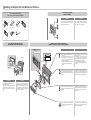
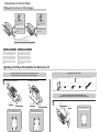
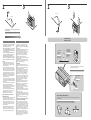
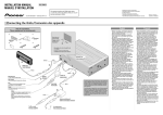
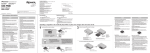
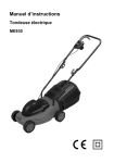
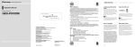
CDX-FM1289
CDX-FM1287
CDX-FM687
INSTALLATION MANUAL
MANUEL D’INSTALLATION
Published by Pioneer Corporation.
Copyright © 2002 by Pioneer Corporation.
All rights reserved.
This product conforms to CEMA cord colors.
Le code de couleur des câbles utilisé pour ce produit est conforme à CEMA.
Publication de Pioneer Corporation.
Copyright © 2002 Pioneer Corporation.
Tous droits de reproduction et de traduction réservés.
<KFJFF/02H00000> <CRD3732-A/N> UC
Printed in Thailand
Imprimé en Thaïlande
Connecting the Units/Connexion des appareils
The figure shows this product with CDX-FM1287 as an example./L’illustration montre, à titre d’exemple, ce produit avec le CDX-FM1287.
Parts for connection/
Pièces requises pour les raccordements
A
B
C
Pass leads and
cords through.
Engagez cordons
et câbles dans
l’ouverture.
D
E
D
F
Pass leads and cords through D and
fix in place.
Engagez cordons et câbles dans
l’ouverture D et assurez leur fixation.
< IP-BUS OUTPUT >
CD Player unit
< SORTIE IP-BUS >
Unité de lecteur CD
A
5.5 m
(18ft.1in.)
Display unit
E
Unité d’affichage
5.4 m
(17ft.9in.)
1m
(3ft.3in.)
Choke coil
Bobine d’arrêt
Resistor
Black (ground)
To the vehicle (metal) body.
C
Noir (masse)
Vers la carrosserie (masse) du véhicule.
Red
To electric terminal controlled by ignition switch
(12 V DC) ON/OFF.
F
Resistore
Fuse holder
30 cm
(12in.)
Porte-fusible
Rouge
Vers une borne commandée par la clé de contact
(12 V CC).
Yellow
To the terminal always supplied with power
regardless of ignition switch position.
Jaune
Vers une borne alimentée en permanence,
indépendamment de la position de la clé de
contact.
Cords for this product and those for other products
may be different colors even if they have the same
function. When connecting this product to another
product, refer to the supplied Installation manuals
of both products and connect cords that have the
same function.
Les câbles de cet appareil et ceux d’autres appareils
peuvent fort bien ne pas être de la même couleur
bien que remplissant la même fonction. Pour relier
cet appareil à un autre appareil, utilisez le manuel
d’installation de chacun et effectuez les raccordements en ne tenant compte que de la fonction de
chaque câble.
B
50 cm
(1ft.8in.)
Antenna switching unit
Unité de commutateur d’antenne
English
Français
• Before mounting, connect the units temporarily. Check that the units and the system
are working correctly.
• After connection is complete, press the clear
button on the CD player with the tip of a pencil.
• Be sure to connect the ground lead (black) to
the vehicle body or some other metal part
that is properly grounded to the chassis. If
the ground lead is not properly connected,
noise may occur or the system may not
operate correctly.
• This unit is for vehicles with a 12-volt battery
and negative grounding. Before installing it
in a recreational vehicle, truck, or bus, check
the battery voltage.
• To avoid shorts in the electrical system, be
sure to disconnect the battery (–) cable
before beginning installation.
• Check whether installation and wiring have
been completed correctly. Replace the
removed car components, then connect the
end of the cable to the negative (–) terminal
of the battery.
• Secure the wiring with cable clamps or
adhesive tape. To protect the wiring, wrap
adhesive tape around them where they lie
against metal parts.
• Route and secure all wiring so it cannot
touch any moving parts, such as the gear
shift, handbrake, and seat rails. Do not route
wiring in places that get hot, such as near
the heater outlet. If the insulation of the
wiring melts or gets torn, there is a danger
of the wiring short-circuiting to the vehicle
body.
• Do not pass the yellow lead through a hole
into the engine compartment to connect to
the battery. This will damage the lead insulation and cause a very dangerous short.
• Do not shorten any leads. If you do, the protection circuit may fail to work when it
should.
• Never feed power to other equipment by
cutting the insulation of the power supply
lead of the unit and tapping into the lead.
The current capacity of the lead will be
exceeded, causing over heating.
• Replace fuses only with the types stipulated
on the fuse holder.
• Even if the power is cut off because the
power cord is removed or the battery is
replaced, the CD title display and ITS memory are retained for 24 hours.
• Avant l’installation, retirer la goupille de
transport et raccorder provisoirement les
appareils. Vérifier que les appareils et la
chaîne fonctionnent correctement.
• Lorsque le raccordement est effectué,
appuyer sur le bouton d’annulation du
lecteur CD avec la pointe d’un crayon.
• Veiller à bien raccorder le conducteur de
masse (noir) à la carrosserie du véhicule ou
à toute autre pièce métallique correctement
mise à la masse sur le châssis. Si le conducteur de masse n’est pas raccordé correctement, il ourrait en résulter des parasites, ou
la chaîne pourrait ne pas fonctionner correctement.
• Cet appareil est destiné aux véhicules avec
une batterie de 12 V, négative à masse négative. Avant de l’installer dans un véhicule de
loisir, un camion ou un car, vérifier la tension de la batterie.
• Afin d’éviter des court-circuits dans le système électrique, s’assurer de déconnecter le
câble (–) de batterie avant de commencer
l’installation.
• Vérifier si l’installation et le câblage ont été
complétés correctement. Remplacer les
composantes de voiture retirées, puis connecter l’extrémité du câble à la borne négative (–) de la batterie.
• Fixer le câblage au moyen des attaches de
câble ou une bande adhésive. Pour protéger
le câblage, enrouler la bande adhésive
autour des câbles à l’endroit où ceux-ci sont
placés contre les parties métalliques.
• Acheminer et fixer tout le câblage de telle
sorte qu’il ne touche pas les pièces mobiles,
comme le levier de changement de vitesse,
le frein à main et les rails des sièges. Ne pas
acheminer les câbles dans des endroits qui
peuvent devenir chauds, comme près de la
sortie de radiateur.
Si l’isolation des câbles fond ou se déchire, il
existe un danger de court-circuit des câbles
avec la carrosserie du véhicule.
• Ne faites pas passer le conducteur jaune
dans le compartiment moteur par un trou
pour le connecter avec la batterie. Ceci
endommagerait l’isolation du conducteur et
causerait un dangereux court-circuit.
• Ne pas court-circuiter les conducteurs.
Sinon, le circuit de protection risque de ne
pas fonctionner.
• Ne jamais alimenter un autre appareil en
coupant l’isolation du conducteur d’alimentation de l’appareil et en la branchant dans
le conducteur. L’intensité de courant du conducteur sera dépassée provoquant ainsi une
surchauffe.
• Remplacer les fusibles seulement par des
fusibles de type spécifié sur le porte-fusible.
• Même si l’alimentation est interrompue du
fait que le câble d’alimentation a été déconnecté ou que la pile a été remplacée,
l’affichage de titres de CD et la mémoire ITS
resteront conservés pendant 24 heures.
< IP-BUS OUTPUT >
• Use this output when connecting a Multi-CD
controller using a separately sold IP-BUS
cable. If you perform this connection, do not
connect this unit's supplied display unit or
antenna switching unit. Also, after connecting, be sure to press the Clear button.
< SORTIE IP-BUS >
To FM car radio
Car antenna plug
Vers Auto radio FM
Fiche d’antenne de Voiture
• Utilisez cette sortie pour relier un lecteur de
CD à chargeur au moyen d’un câble IP-BUS
vendu séparément. Si vous réalisez cette
liaison, ne raccordez pas l’unité d’affichage
ni l’unité de commutation d’antenne de cet
appareil. La liaison une fois effectuée,
n’oubliez pas d’appuyer sur la touche
d’effacement.
Installing the Display Unit/Installation de l’afficheur
Removing the Display Unit/
Enlever de I’afficheur
Parts for display unit mounting/
Pièces requises pour le montage de l’afficheur
A
B
×1
C
×1
(Rough surface)
(Surface rugueuse)
E
F
×1
(Soft surface)
(Surface douce)
G
×2
×1
×1
English
3
2
D
×1
Insert the G that comes with the unit as
shown in the illustration. Turn it to the left
and then pull it towards you.
Français
Insérer la pièce G fournie avec l’appareil
comme montré sur l’illustration. La tourner
vers la gauche puis la tirer vers soi.
1
Fasten the display unit with Velcro tape/
Fixer I’afficheur à I’aide d’une bande Velcro
Installation using the flush mounting bracket/
Installation au moyen du support du montage affleurant
English
Français
1
Start by opening installation holes in the
console, etc.
• When opening holes in the console, etc.,
confirm that there is no object at the rear
of the console, and be careful not to cut
off the power supply cord.
• A minimum depth of 20 mm is required
for installation of the flush mounting
bracket.
Tout d’abord, percer les trous d’installation
dans la console, etc.
• Avant de percer les trous dans la console,
s’assurer que l’on peut le faire sans danger et veiller à ne pas endommager les
câbles d’alimentation électrique.
• La profondeur minimale requise pour le
support de montage affleurant est de
20 mm.
2
Fit the D into the opening in the console,
etc., raise the claws of the D with a flatbladed screwdriver, and secure the bracket
in place.
Engager la pièce D dans l’ouverture de la
console, etc., soulever les griffes de la pièce
D au moyen d’un tournevis plat et assurer
de cette manière le maintien du support.
3
Fit the E into the D (the top and bottom of
the holder are predetermined), then secure
it with F.
Engager la pièce E dans la pièce D (les
parties supérieure et inférieure du support
sont repérées) et assurer le maintien au
moyen de F.
4
Pass the display unit (A) cord through the
hole in the holder, and fit the display unit
into the holder.
Faire cheminer le cordon de l’afficheur (A)
à travers le trou du support puis engager
l’afficheur dans le support.
Claws
Raise the claws.
Console, etc.
40 – 41 mm
Mâchoires
Soulevez les mâchoires.
110 – 111 mm
Console, etc.
Velcro tape
Bande Velcro
Velcro tape
Bande Velcro
English
Français
• Thoroughly wipe off the surface before
affixing the Velcro tape.
• Obviously, it is very dangerous if the cord
gets tangled in the steering wheel, so
install the cord so that it cannot get in the
way.
• Essuyez soigneusement la surface avant
d’attacher le morceau de bande Velcro.
• Il est naturellment dangereux si le cordon
sera enchevêtré au volant de direction, et
il faudra donc installer le cordon de telle
façon qu’il ne soit pas pris.
D
E
F
A
Transportation of multi-CD Player/
Transport du lecteur de CD à chargeur
Seal
After removing the transport
screw, cover the hole with the
supplied seal.
Seal
After removing the transport
screw, cover the hole with the
supplied seal.
Cache
Après avoir retiré la vis de transport, bouchez le trou au moyen
du cache fourni.
Cache
Après avoir retiré la vis de transport, bouchez le trou au moyen
du cache fourni.
Transport screw
Attach to the original position before transporting the set.
Vis de transport
Replacez ces vis dans leur position d’origine avant de transporter I’appareil.
English
Français
A transport screw has been attached to the
set in order to protect it during transportation. After removing the transport screw,
cover the hole with the supplied seal. Be
sure to remove the transport screw before
mounting the set. The removed transport
screw should be retained in the accessory
bag for use the next time the set is transported.
Des vis sont fixées sur le lecteur de façon à
le protéger pendant le transport. Après
avoir retiré la vis de transport, bouchez le
trou au moyen du cache fourni. Veillez à
retirer ces vis avant d’installer le lecteur.
Conservez les vis dans le sac contenant les
accessoires de manière à ne pas les égarer
et à être en mesure de les remettre en place
en cas de transport.
Installing the CD Player Unit/Installation de la Unité lecteur CD
Mounting the player on the mounting board with self-tapping screws/
Fixation du lecteur sur une platine à I’aide de vis autotaraudeuses
1
Mounting parts/Pièces de fixation
Refer to the following illustrations of mounting parts when mounting the player.
Horizontally/Horizontalement
Vertically/Verticalement
B
A
A
A
B
B
×2
A
C
×4
×4
×4
B
B
Mounting board
Put marks.
Mounting board
Put marks.
Marquez ces emplacements.
Platine
Marquez ces emplacements.
Use the holes indicated with arrows.
Use the holes indicated with arrows.
Percez les trous indiqués par les flèches.
Percez les trous indiqués par les flèches.
1
Put marks.
Marquez ces emplacements.
B
Parcel shelf
Plage arrière
Use the holes indicated with arrows.
Percez les trous indiqués par les flèches.
A
A
A
E
D
Suspending the player from the parcel shelf with hex-screws/
Fixation du lecteur sous la plage arrière au moyen de vis à tête hexagonale
A
Platine
Les pièces servant à la fixation du lecteur sont illustrées cidessous.
A
A
B
×4
2
3
2
C
3
E
φ 6.5 ~ 7 mm
C
E
φ 4 ~ 4.5 mm
The following steps are the same for horizontal or vertical installation.
Les opérations suivantes sont les mêmes, que
l’installation de l’appareil soit horizontale ou verticale.
D
D
English
Français
• Consult with your nearest dealer if installation requires the drilling of holes or other
modifications of the vehicle.
• Before finally installing the unit, connect the
wiring temporarily and make sure it is all
connected up properly and the unit and the
system work properly.
• Use only the parts included with the unit to
ensure proper installation. The use of unauthorized parts can cause malfunctions.
• When mounting the player, make sure none
of the leads are trapped between the player
and the surrounding metalwork or fittings.
• Consultez le concessionnaire de votre
véhicule si l’installation exige le percement de trous ou toute autre modification
du véhicule.
• Avant d’installer définitivement l’appareil,
reliez provisoirement les câbles et
assurez-vous que tout est correct et que
l’ensemble fonctionne normalement.
• Pour réaliser une bonne installation,
n’utilisez que les pièces fournies avec
l’appareil. L’emploi de pièces non
fournies peut provoquer une anomalie de
fonctionnement.
• Installez l’appareil de manière qu’aucun
câble ne soit écrasé entre le lecteur et les
pièces métalliques voisines.
Location
• Install the unit where it does not get in
the driver’s way and cannot injure the
passenger if there is a sudden stop, like
an emergency stop.
• Be sure to mount the player on a rigid
surface which is firm enough to hold the
player in the proper position under all circumstances. Failure to do so may affect
the optimum performance of the player.
• Before drilling a hole into the trunk, confirm that there is nothing behind the hole.
Never drill a hole in the fuel tank or any
other important part.
• Do not mount the player near the heater
outlet, where it would be affected by heat,
or near the doors, where rainwater might
splash onto it.
• Do not mount the player on the spare tire
board or any other unstable place.
• Mount the player in a place where it does
not prevent the spare tire, jack, or tools
from being easily removed.
• Do not mount the player anywhere that
gets the sun and so becomes hot, like on
the dashboard or the rear shelf.
• Mount the player on a flat surface.
Suspending the player from the parcel
shelf with hex-screws
• Ideally, when the player is being mounted
under the parcel shelf, two persons
should work together. One person should
hold the player, and the other should
tighten the hex-nuts. If you do this job on
your own, take great care not to drop or
knock the player.
• When suspending the player under the
parcel shelf, be sure that it is firmly
installed on a solid surface. If the unit is
not firmly installed, skipping will occur.
Emplacement
• Installez l’appareil de manière qu’il ne
gêne pas le conducteur et qu’il ne puisse
pas blesser un occupant du véhicule en
cas de freinage brusque.
• Fixez l’appareil à une surface rigide suffisamment solide pour le maintenir en
toutes circonstances, faute de quoi ses
performances pourraient être altérées.
• Avant de percer une cloison, assurezvous que vous n’endommagerez aucune
pièce pouvant se trouver derrière cette
cloison. Ne percez aucun trou dans le
réservoir de carburant ou toute autre
pièce importante.
• N’installez pas l’appareil près des ouïes
du chauffage en raison de la chaleur
dégagée, ni près des portières en raison
de l’exposition aux intempéries.
• N’installez pas l’appareil sur la plaque
cachant la roue de secours ni sur toute
autre surface amovible.
• Installez l’appareil dans un endroit qui ne
gêne pas le retrait de la roue de secours,
du cric et des outils.
• N’installez pas l’appareil dans un endroit
où il sera exposé à la lumière directe du
soleil tel que la plage arrière ou le tableau
de bord.
• Fixer le lecteur sur une surface plate.
Fixation du lecteur sous la plage arrière au
moyen de vis à tête hexagonale
• Pour installer le lecteur sous la plage
arrière, il est préférable de travailler à
deux; une personne peut alors maintenir
le lecteur tandis que l’autre pose les vis.
Si vous devez procéder seul à cette installation, veillez à ce que le lecteur soit provisoirement maintenu en position de
manière qu’il ne tombe pas dans le coffre
pendant les opérations de fixation.
• Si vous installez le lecteur sous la plage
arrière, veillez à ce qu’il soit solidement
fixé, faute de quoi des erreurs de lecture
peuvent se produire.
Mounting angle/
Angle de montage
Use any angle in
this range (up to
90 degrees).
Tout angle compris entre 0 et 90
degrés convient.
Top
Sommet
The player cannot be installed
in this direction.
Le lecteur ne
peut pas être
installé de cette
manière.
The angle switching dial must be set on both sides of
the player to the same position.
Les boutons de commutation d’angle placés de chaque
côté du lecteur doivent occuper les mêmes positions.
Angle switching
dial
Sélecteur d’angle
de montage
5 steps
5 positions
Angle switching dial adjustment
Set the dial so that its slot is closest to the horizontal direction with respect to the
ground surface.
Positionnement du sélecteur d’angle de montage
Positionnez le sélecteur de manière que la fente soit horizontale.