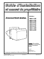
1
ÉVACUATEUR MURAL
-0403
DNS
Modèles :
SMH-1-DE
SMH-3-DE
SMH-4-DE
SMH-5-DE
SMH-6-DE
SMH-1-BR
SMH-4-BR
Rév.A
Attention : Ne pas altérer
votre unité ou ses contrôles.
Appeler un technicien
qualifié.
Fabriqué par :
Conservez ce manuel pour références ultérieures.
Imprimé au Canada
Imprimé sur papier 100% recyclé
2011-02-18
DETTSON
Industries Dettson inc.
3400, boulevard Industriel
Sherbrooke, Québec - Canada
J1L 1V8
X40010 Rev. H
SECTION 1
INSTALLATION
1.1)
DANGER, MISE EN GARDE ET
AVERTISSEMENT
Comprenez bien la portée des mots suivant :
DANGER, MISE EN GARDE ou AVERTISSEMENT.
Ces mots sont associés aux symboles de sécurité.
Vous les retrouverez dans le manuel de la façon
suivante :
!
DANGER
Le mot DANGER indique les plus graves
dangers, ceux qui provoqueront des blessures
corporelles sérieuses ou la mort.
! MISE EN GARDE
L’expression MISE EN GARDE signifie un
danger qui peut entraîner des blessures
corporelles ou la mort.
AVERTISSEMENT
Quant au mot AVERTISSEMENT, il est utilisé
pour indiquer les pratiques dangereuses qui
peuvent provoquer des blessures corporelles
mineures ou des dommages à l’appareil ou à la
propriété.
ASSUREZ-VOUS QUE L'ENDROIT OÙ EST SITUÉ LA
BOUCHE D'ÉVACUATION DE L'APPAREIL EST, EN
TOUT TEMPS, LIBRE D'OBSTRUCTIONS, DE
DÉBRIS, OU D'ACCUMULATIONS DE NEIGE...
NOTES POUR L'INSTALLATEUR
La longueur minimale mesurée de tuyau à fumée est de
30 pouces avec le régulateur de tirage à 18 pouces de
la sortie de l'unité de chauffage. Ceci inclus un
maximum de 2 coudes 90o. Voir la figure 1. Donc la
longueur minimale équivalente de tuyau de
raccordement est de 22.5 pieds (un coude de 90o est
équivalent à 10 pieds de tuyau à fumée et un coude de
45o est équivalent à 5 pieds).
La longueur maximale mesurée de tuyau à fumée est
de 20 pieds entre la sortie de l'unité de chauffage et
l'entrée de l'évacuateur mural. Ceci inclus un maximum
de 4 coudes de 90o. Voir la figure 1. Donc la longueur
maximale équivalente est de 60 pieds.
Lorsque tous les ajustements sont complétés, selon ce
manuel d'instruction et le manuel d'instruction de votre
unité de chauffage, il est recommandé de vous assurer
que la température à l'entrée de l'évacuateur mural est
au minimum 200o F (93o c). Dans le cas où cette
température minimale n'est pas atteinte dans les 5
minutes suivant un départ à froid, il est recommandé de
l'augmenter par l'une, ou une combinaison des options
suivantes :
•
Relocaliser le générateur d'air chaud ou la
chaudière de façon à raccourcir la longueur du
tuyau à fumée;
•
Utiliser un évent de type "L" en amont de
l'évacuateur mural;
•
Isoler le tuyau à fumée en amont de l'évacuateur
mural. Pour ce faire, utilisez 1 pouce de laine
isolante de type microlite FSK de John Mansville ou
un équivalent. Avec cet isolant, entourez le tuyau à
fumée et utilisez du ruban aluminium haute
température pour l'attacher. Laissez l'ouverture du
régulateur de tirage libre de toute obstruction.
Après ces modifications, attendez 30 minutes pour
laisser le système se refroidir et ensuite remesurez la
température à l'entrée de l'évacuateur mural après 5
minutes d'opération. La température doit maintenant
être au-dessus de 200o F (93o C).
3
1.2)
INSTALLATION
Cet appareil doit être installé par un technicien qualifié
en accord avec ces instructions et le code d'installation
ACNOR B139 article 4.3. Si cet appareil est installé
incorrectement, une situation dangereuse pourrait en
résulter.
L'évacuateur mural ne doit pas être installé sur un
incinérateur, une toilette incinératrice, un appareil de
combustion à condensation ou un appareil de chauffage
à carburant solide.
•
•
•
•
Cette installation doit respecter les codes et règlements
des autorités ayant juridiction.
L'évacuateur mural peut être installé à travers un mur
combustible d'un maximum de 8 pouces ou à travers
d'un mur non-combustible d'un maximum de 16 pouces
incluant une partie combustible d'un maximum de 8
pouces.
•
•
La bouche d'évacuation ne doit pas être située en
dedans de 6 pieds de toute sortie d'évacuation de
régulateur de gaz ou 3 pieds de tout tuyau
d'évent de réservoir d'huile ou de tuyau de
remplissage de réservoir d'huile;
La bouche d'évacuation ne doit pas être située en
dedans de 6 pieds de tout édifice adjacent ou du
coin de toute structure en L;
La bouche d'évacuation ne doit pas être située à
moins de 6 pieds de toute entrée d'air de
combustion d'un autre appareil;
La partie inférieure de la bouche d'évacuation ne
doit pas être installée à moins de 1 pied audessus de toute surface pouvant supporter neige,
glace ou débris;
La bouche d'évacuation ne doit par être localisée
de façon à ce que les gaz d'évacuation ou la
température de ceux-ci endommagent la brique,
le mortier, le bois ou tout autre construction;
La bouche d'évacuation ne doit pas être localisée
sous une véranda, portique ou plate-forme.
L'utilisation d'un évent de type "B" est interdite sur le
système d'évacuation.
1.3)
1.2.1) Instructions générales d'installation
La première étape de l'installation de cet évacuateur
mural est de trouver un endroit sur le mur extérieur qui
respecte toutes les clauses suivantes :
• La bouche d'évacuation de l'évacuateur mural ne
doit pas être installée à moins de 7 pieds audessus d'une entrée pavée pour automobiles ou
d'un trottoir pavé;
• Un système d'évacuation mural ne doit pas être
situé à moins de 6 pieds d'une entrée mécanique
d'air frais d'un édifice incluant une ouverture de
corniche, d'une fenêtre, d'une porte ou d'une
ligne de propriété;
• La bouche d'évacuation ne doit pas être installée
au-dessus d'un compteur/régulateur de gaz en
étant à moins de 3 pieds horizontalement de la
ligne centrale de l'axe vertical du régulateur;
• L'évacuateur mural ne doit pas être installé à
moins de 1 pied du niveau du sol;
• La bouche d'évacuation des gaz ne doit pas être
située au-dessus d'une entrée d'auto pavée ou
d'un trottoir pavé situé entre 2 édifices, dans le
cas où cette entrée ou ce trottoir est commun aux
deux habitations;
• La bouche d'évacuation doit être installée de
façon à ce que les gaz de combustion ne
puissent être dirigés vers les personnes, ne
surchauffent pas les structures combustibles ou
ne pénètrent pas dans les ouvertures d'édifices
situés à moins de 6 pieds.
4
Liste des composantes
Veuillez consulter la figure 1. Les composantes
expédiées avec l'évacuateur mural sont les suivantes :
a. L'assemblage principal "moteur-ventilateur". Ceci
consiste en une boîte dont le cabinet extérieur en
acier inoxydable brillant. Numéro de pièce SWV1M-2S ou SWV-2M-2S;
b. Une boîte de jonction pré-assemblée avec le
détecteur de pression, numéro R99F001;
c. Un adapteur 3 – 6 pouces avec clapet anti-retour
inclus. Numéro de pièce FD-02;
d. Un connecteur de 6 à 5 pouces pour l'ensemble
SMH-3. Numéro de pièce Z07F010;
e. Un connecteur de 6 à 8 pouces pour l'ensemble
SMH-5. Numéro de pièce Z07F005.
1.4)
Installation de l'évacuateur mural
Vérifiez si l'évacuateur mural est dimensionné
correctement selon le tableau 1. L'unité de chauffage
doit être raccordée en amont du tuyau d'entrée de
l'évacuateur mural.
Vous devez installer un régulateur barométrique de
tirage comme spécifié dans le manuel d'installation de
l'unité de chauffage. Consulter la figure 1.
TABLEAU 1
Table de sélection de l'évacuateur mural
Unité de chauffage
MODÈLE
Tuyau de
raccord ( " )
Input
(USGPH)
Évacuateur
mural
AM(i)-076 @ 110
6
0.65 @ 0.92
SWV-1M-2S
SMH-1-DE
Beckett ou Riello
AM(i)-120 @ 140
6
1.00 @1.20
SWV-2M-2S
SMH-4-DE
Beckett ou Riello
AME-15 @ 25
6
0.65 @ 0.85
SWV-1M-2S
SMH-1-DE
Beckett ou Riello
AM(i)T-075 @ 105
5
0.50 @ 0.75
SWV-1M-2S
SMH-3-DE
Beckett ou Riello
AM(i)T-120 @ 155
6
0.85 @ 1.10
SWV-2M-2S
SMH-4-DE
Beckett ou Riello
HM(R)-080 @ 121
5
0.75 @ 1.00
SWV-1M-2S
SMH-3-DE
Beckett ou Riello
HM(i)-103 @ 159
6
0.85 @ 1.35
SWV-2M-2S
SMH-4-DE
Beckett ou Riello
HM-185 @ 212
8
1.50 @ 1.75
SWV-2M-2S
6-8
SMH-5-DE
Beckett ou Riello
HMD-124 @ 208
7
1.00 @ 1.50
SWV-2M-2S
6-7
SMH-6-DE
Beckett ou Riello
HME-15 @ 20
6
0.65 @ 0.75
SWV-1M-2S
SMH-1-DE
Beckett ou Riello
HME-23 @ 25
6
0.85 @ 1.10
SWV-2M-2S
SMH-4-DE
Beckett ou Riello
HML-115 @ 175
6
1.00 @ 1.50
SWV-2M-2S
SMH-4-DE
Beckett ou Riello
HMT-012 @ 018
6
1.00 @ 1.50
SWV-2M-2S
SMH-4-DE
Beckett ou Riello
HMS-027 @ 035
6
0.65 @ 0.85
SWV-1M-2S
SMH-1-DE
Beckett ou Riello
HMS-041 @ 062
6
1.00 @ 1.50
SWV-2M-2S
SMH-4-DE
Beckett ou Riello
AMP-075 @ 105
5
0.50 @ 0.75
SWV-1M-2S
SMH-3-DE
Beckett ou Riello
AMP-120 @ 155
6
0.85 @ 1.10
SWV-2M-2S
SMH-4-DE
Beckett ou Riello
LO-1MQH-3M*
5
0.65 @ 1.00
SWV-1M-2S
6 – 5*
SMH-1-BR
Brock ou Riello
FBR-1*
5
0.65 @ 1.00
SWV-1M-2S
7 - 5*
SMH-1-BR
Brock
MBP*
5
0.65 @ 1.00
SWV-1M-2S
6 - 5*
SMH-1-BR
Brock , Beckett ou Riello
MBP-U*
5
0.65 @ 0.85
SWV-1M-2S
6 - 5*
SMH-1-BR
Beckett
MBP-F*
5
0.65 @ 1.00
SWV-2M-2S
6 - 5*
SMH-4-BR
Brock, Beckett ou Riello
CCC*
5
0.50 @ 0.85
SWV-1M-2S
SMH-1-BR
Brock, Beckett ou Riello
LO-2M*
5
1.10 & 1.25
SWV-2M-2S
7 - 5*
SMH-4-BR
Brock
MBP-2*
5
1.10 & 1.25
SWV-2M-2S
6 - 5*
SMH-4-BR
Brock ou Riello
IB-30 / IB32-R*
5
0.65 @ 0.75
SWV-1M-2S
6 - 5*
SMH-1-BR
Beckett ou Riello
30-RB*
5
0.65
SWV-1M-2S
6 - 5*
SMH-1-BR
Beckett
32E2*
5
0.75
SWV-1M-2S
6 - 5*
SMH-1-BR
Brock
50E2 / IB50-O*
5
0.65 @ 0.75
SWV-1M-2S
6 - 5*
SMH-1-BR
Brock ou Riello
*
Réducteur
(")
6-5
6-5
6-5
# de modèle
complet
Brûleur
L’ensemble d’évacuation ne comprend pas le réducteur pour utiliser un tuyau de raccordement de 5 pouces
diamètre.
5
1.4.1) Préparation et obligations
Trouvez un endroit sur le mur extérieur pour installer
l'évacuateur mural en respectant les clauses de la
section 1.2.1. Consultez la figure 2 pour les
dimensions principales du système.
Trouvez le meilleur endroit possible sur le mur
intérieur pour installer la boîte de jonction-détecteur de
pression. Voir la figure 3. En utilisant le gabarit de
montage expédié dans la boîte de l'évacuateur
comme guide, percez les trous (trou du tuyau, trous
des boulons d'ancrage, etc.) dans le mur extérieur aux
locations désirées.
1.4.4) Raccordements à la boîte de
jonction
Les seuls raccordements non électriques, en ce qui
concerne l'installation de la boîte de jonction, sont
l'installation de la boîte sur le mur intérieur et le
raccordement du tube de pression au détecteur de
pression.
L'assemblage "moteur-ventilateur" de même
que le détecteur de pression doivent être
installés avec le détecteur de pression en
position verticale de façon a ne pas fausser la
lecture de pression et ne pas endommager les
roulements des moteurs.
Installez la boîte de jonction, sur le mur intérieur, aussi
près que possible de l'endroit où le tuyau pénètre
dans le mur. Fixez cette boîte sur le mur en vous
assurant que le détecteur de pression est en position
verticale. Voir les figures 3 et 4. Raccordez le tube de
pression de l'évacuateur mural sur l'accouplement du
détecteur de pression situé sur le côté de la boîte de
jonction. Assurez-vous en raccordant ce tuyau que les
pliages dans le tuyau sont doux et graduels, et que le
tuyau n'est pas bloqué par un pliage de 90o trop
brusque. Assurez-vous de plus, que la connexion sur
l'accouplement du détecteur de pression soit serré de
façon à éviter toute fuite. Ne pas serrer à l'extrême,
car l'accouplement pourrait être endommagé. Vous ne
devez pas utiliser de ruban téflon sur ce
raccordement.
1.4.2) Montage sur un mur combustible
1.5)
! MISE EN GARDE
! MISE EN GARDE
Ne pas enlever le tuyau de protection
extérieur ("sleeve") dans le cas des murs
combustibles. Ce tuyau est nécessaire dans
le cas des murs combustibles.
Amenez l'unité à l'extérieur et, de l'extérieur, insérez le
tuyau de l'évacuateur dans le trou en poussant jusqu'à
ce que la plaque de mur extérieur soit en contact
uniforme avec le mur extérieur. Montez en place à
l'aide de 4 vis d'ancrages. Si le mur extérieur est fait
de ciment, briques ou mortier, vous aurez besoin
d'ancrages pour ciment. Voir la figure 4A.
1.4.3) Installation sur mur
non-combustible
Retirez le tuyau de protection comme montré sur la
figure 4B. Pour le retirer, vous n'avez qu'à déplier les
"oreilles" le retenant à la plaque de montage. De
l'extérieur, insérez le tuyau de l'évacuateur dans le trou
en poussant jusqu'à ce que la plaque de mur extérieur
soit en contact uniforme avec le mur. Monter en place à
l'aide de 4 vis d'ancrages. Vous aurez besoin
d'ancrages pour ciment. Voir la figure 4B.
6
Branchement de l'unité de chauffage
à l'évacuateur mural
Vérifiez le diamètre du tuyau de raccordement selon la
charte détaillée au tableau 1. Installez un tuyau de
raccordement proprement dimensionné entre la sortie
de l'unité de chauffage et l'entrée du volet anti-retour.
1.6)
Installation du volet anti-retour
Le système d'évacuation doit absolument être muni du
volet anti-retour fourni dans la boîte lors de
l'expédition. Ce volet sert à prévenir le refoulement
d'air froid dans la maison hors cycle et tous les
problèmes qui se rattachent à ce phénomène. Il faut
d'abord installer le réduit 3 à 6 pouces sur le tuyau de
3 pouces de l'évacuateur. Selon votre modèle, Il se
peut que ce réduit soit déjà en place. Le volet doit être
installé avec la flèche pointant dans la direction des
gaz de combustion soit vers l'évacuateur. De plus, le
volet anti-retour doit reposer sur la fermeture fixe
lorsque l'unité n'est pas en marche. Pour ce faire, le
volet doit être installé en POSITION HORIZONTALE
avec la flèche sur le DESSUS du tuyau. (Mettre le
volet au niveau sur les 2 axes). DE PLUS CE VOLET
DOIT ETRE INSTALLE SANS ALTERATION. Si cette
condition n'est pas respectée, le fonctionnement de
l'évacuateur peut être imprévisible et erratique.
1.7)
INSTALLATION SUR MUR 20
POUCES
Si vous voulez installer l’évacuateur mural sur un mur
de plus de 8 pouces d’épaisseur, vous devez installer
à ce niveau, l’ensemble d’extension de mur fournit en
option. Cet ensemble optionnel consiste en un
extension de 16 pouces du tuyau de fumée de
l’évacuateur (numéro de pièce B01297-01). Pour
installer cet ensemble, se référer aux instructions
d’installation de cet ensemble.
1.8)
BRANCHEMENT ÉLECTRIQUE
Ces fils doivent être protégés par une gaine de
protection approuvée style B-X. Leurs couleurs
doivent correspondre à celles montrées sur les
figures 5.
Dans un tel raccordement, la commande à
l'évacuateur mural vient de l'unité de chauffage par le
contrôle opérationnel. Lorsque l'état de débit d'air
d'évacuation se stabilise, le détecteur de pression
ferme le circuit et démarre le brûleur. Lorsque le
contrôle opérationnel cesse de demander, le brûleur
arrête immédiatement et l'évacuateur mural continue
de fonctionner pendant 5 minutes pour évacuer les
gaz de combustion résiduels dans le système.
Choisir le diagramme électrique à utiliser en fonction
du type d’appareil et de brûleur. Référer au tableau 2.
L'installation doit être conforme aux codes et
règlements des autorités ayant juridiction. Voir le code
CSA B139. Vous devez utiliser pour tout filage, des
câbles de jauge 16 approuvé pour 105o C (221o F).
TABLEAU 2
FIGURE
5A
5B
5C
5D
5E
5F
5G
5H
5I
5J
5K
5L
5M
MODÈLES
AMI, AMT-IM et OLS
AMT-SM et OSR
AMI et HE
AMI et HE
AMT-SM et OSR
AMP et OMP
AMP et OMP
LO-1MQH, LO-2M, FBR-1, LO-1M3M, MBP, MBP-F, MBP-2 et MBP-U
BRF et BFF
HMT, HML, HMI et HMD, aquastat triple
HMR, HMT, HML, HMI et HMD, aquastat double
Chauffe-eau, 30RB, 32E2, 50E5, IB-30, IB32-R et IB50-O
AME et HME
BRÛLEUR
Beckett ou Riello
Beckett
Beckett
Riello
Riello
Riello
Beckett
Beckett
Beckett
Beckett ou Riello
Beckett
Beckett
Beckett
7
SECTION 2
OPÉRATION
2.1)
MISE EN MARCHE ET
AJUSTEMENTS
2.2.1) Test d’ignition
Pour les instructions de démarrage de votre unité de
chauffage, veuillez consulter le manuel d'instruction
l'accompagnant. Le démarrage de votre système de
chauffage avec évacuateur mural est identique.
L'évacuateur mural ne sert qu'à simuler une
cheminée.
2.1.1) Ajustement du tirage
Le tirage du système doit être ajusté de façon à
obtenir, en amont du régulateur de tirage, la valeur
spécifiée au tableau 3. Ces spécifications sont en
accord avec les instructions des unités de chauffage.
TABLEAU 3
Ajustement de tirage
Modèle de l'unité de chauffage
-0.035
HMD et HM(i)-1.50 USGPH et plus
-0.050
2.2)
Ce test doit être fait pour vérifier le fonctionnement
normal du détecteur de pression. Lorsque le brûleur
est en fonction, bloquez (avec un morceau de carton
par exemple) la bouche d'évacuation de l'évacuateur
mural. Lorsque le blocage est complet, le brûleur doit
arrêter. Celui-ci doit redémarrer une fois que
l'obstruction est enlevée. Ce démarrage doit être en
douceur. Si ce détecteur de débit ne fonctionne pas,
vous devez le changer. Ce détecteur n'est pas
ajustable et doit être remplacé lors d'un fonctionnement anormal.
2.2.3) Vérification du délai post-purge de 5
minutes
Pour vérifier le fonctionnement du délai post-purge,
laissez fonctionner l'unité pour une période minimum
de 5 secondes. Fermez le brûleur. Le brûleur devrait
arrêter et l'évacuateur fonctionner pendant 5 minutes.
-0.020
-0.040
VÉRIFICATIONS ET TESTS APRÈS
LA MISE EN MARCHE
Les tests suivants doivent être fait pour assurer un
fonctionnement sûr, fiable et sans problèmes.
8
2.2.2) Détecteur de pression
Tirage ("W.C.)
AME, HME, AM(i), AM(i)T, AMP,
OLS, OSR, OMP, HMT, HML et
HM(i)-1.35 USGPH et moins
LO-1MQH, LO-1M3M, FBR-1,
MBP-U, CCC, MBP, BRF, 30RB,
32E2, 50E2, IB-30, IB32-R et
IB50-O
LO-2M, BFF, MBP-2 et MBP-F
On doit vérifier l'allumage du brûleur en le démarrant
par le thermostat ou le contrôle d’opération. Si
l'ignition ne se fait pas en douceur, consultez le
manuel de l'unité de chauffage.
2.2.4) Vérification du volet anti-retour
En vous servant d'une paire de pinces pour retenir
l'arbre du volet, maintenez celui-ci en position
complètement fermée. Essayez alors de démarrer le
brûleur. Celui-ci ne devrait pas démarrer tant que le
volet anti-retour est en position complètement fermée.
SECTION 3
ENTRETIEN
3.1)
ENTRETIEN
L'évacuateur mural doit être inspecté de façon
biannuelle. Les points d'inspection sont les suivants :
3.1.3) Détecteur de pression
Vérifier le fonctionnement du détecteur de pression en
faisant le test spécifié à la deuxième partie,
section 2.2.2.
3.1.1) Moteurs
3.1.4) Volet Anti-retour
Les deux moteurs doivent tourner librement. Huilez au
début et au milieu de la saison de chauffage avec une
huile spéciale bonne pour –35o C (-30o F). Pour avoir
accès aux moteurs, enlevez le couvert de
l'assemblage moteur-ventilateur.
Le volet anti-retour doit être libre de suie, débris ou
tous matériaux pouvant nuire au passage des gaz.
Retirez toutes les matières étrangères avant de
redémarrer l'unité.
3.1.2) Aube "Cage d'écureuil"
Les deux cages d'écureuils doivent être libre de suie,
débris ou tout matériaux pouvant nuire au passage
des gaz. Retirez toutes les matières étrangères avant
de redémarrer l'unité.
9
FIGURE 1
Système MH – Arrangement général
DNS-0225 Rev.A
FIGURE 2
Dimensions principales du système
DNS-0226 Rev.A
10
FIGURE 3
Location du système SMH sur le mur
DNS-0227 Rev.A
FIGURE 4A
Installation sur un mur combustible
DNS-0228 Rev.A
FIGURE 4B
Installation sur un mur non-combustible
DNS-0229 Rev.A
11
FIGURE 5A
AMI, AMT-IM et OLS 2 vitesses, Beckett ou Riello
DNS-0230 Rev.B
FIGURE 5B
AMT-SM et OLS 2 vitesses, Beckett
DNS-0397 Rev.B
12
FIGURE 5C
AMI et HE 1 vitesse, Beckett
DNS-0231 Rev.B
FIGURE 5D
AMI et HE 1 vitesse, Riello
DNS-0232 Rev.B
13
FIGURE 5E
AMT-SM et OSR 2 vitesses, Riello
DNS-0407 Rev.B
14
FIGURE 5F
AMP et OMP, Riello
DNS-0621 Rev.A
15
FIGURE 5G
AMP et OMP, Beckett
DNS-0622 Rev.A
16
FIGURE 5H
LO-1MQH, LO-2M, FBR-1, LO-1M3M, MBP, MBP-F, MBP-2, CCC et MBP-U
DNS-0239 Rev.A
FIGURE 5I
BRFet BFF
DNS-0238 Rev. A
17
FIGURE 5J
HMT, HML, HMI et HMD avec triple aquastat, Beckett ou Riello
FIGURE 5J
DNS-0233 Rev.C
FIGURE 5K
HMR, HML, HMT, HMI et HMD avec double aquastat, Beckett
DNS-0234 Rev. C
18
FIGURE 5L
Chauffe-eau, 30RB, 32E2, 50E2, IB-30, IB32-R et IB50-O, Beckett
DNS-0240 Rev.A
FIGURE 5M
AME et HME, Beckett
DNS-0235 Rev. A
19
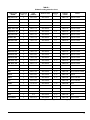
LISTE DES PIÈCES
Modèle : SMH
DNS-0385 Rev. D
ITEM
1A
1B
2
3
4A
4B
5
6
7
8A
8B
9A
9B
10A
10B
11A
11B
12
13A
13B
14
15
16
17
18
19
20
21
22
23
24
25
26
27
28
29
30
31A
31B
32
20
DESCRIPTION
NUMERO
COMMENTAIRES
Ass. volute du souffleur
Ass. volute du souffleur
Isolation de souffleur de sortie
Isolation de souffleur d'entrée
Ass. moteur, SMH-1 et SMH-3
Ass. moteur, SMH-4, SMH-5 et SMH-6
Couvercle
Boîte de jonction du moteur
Couvercle de boîte de jonction
Bande de recouvrement de sortie
Bande de recouvrement de sortie
Isolation de volute de sortie
Isolation de volute de sortie
Bande de recouvrement d'entrée
Bande de recouvrement d'entrée
Isolation de volute d'entrée
Isolation de volute d'entrée
Isolation du support de couvercle
Support de couvercle
Support de couvercle
Garniture, tuyau de sortie
Garniture, tuyau de sortie
Ass. plaque de montage
Isolation de gaine de protection
Tuyau réducteur 6" - 3 1/16"
Ass. volet anti-retour
Commutateur limite SPDT
Panneau diviseur de boîte de jonction, volet anti-retour
Boîte de jonction principale
Couvercle de boîte de jonction principale
Relais de temporisation
Ass. tube de raccord de pression
Détecteur de pression
Ass. boîte de jonction
Moteur de souffleur 1/25 HP
Ensemble d'espaceurs
Ensemble de plaques de moteur
Aube de souffleur 3.812” X 1.50”
Aube de souffleur 3.812” X 2.50”
Huile synthétique
B01391-01
B01391-02
B00732-02
B00732-01
B01231-01
B01231-02
B01233-02
B00826
B00827
B01388-01
B01388-02
B00619-04
B00619-39
B01388-03
B01388-04
B00619-05
B00619-40
B00733
B00705
B01074
B01150
B01044
B01232
B00621-65
B01298
B01002
A00249
B01314
B00828
B00829
B01131
B02075
R99F001
B01228-01
L06J001
K07004
K07005
Z01G001
Z01G002
Z99F019
Pour SMH-1 et SMH-3
Pour SMH-4, SMH-5 et SMH-6
Comprend moteur, aube de souffleur
Comprend moteur, aube de souffleur
Pour
Pour
Pour
Pour
Pour
Pour
Pour
Pour
SMH-1 et SMH-3
SMH-4, SMH-5 et
SMH-1 et SMH-3
SMH-4, SMH-5 et
SMH-1 et SMH-3
SMH-4, SMH-5 et
SMH-1 et SMH-3
SMH-4, SMH-5 et
SMH-6
SMH-6
SMH-6
SMH-6
Pour SMH-1 et SMH-3
Pour SMH-4, SMH-5 et SMH-6
Brun, 1"
Blanc, 1/2"
Comprend commutateur, couvert et fils électrique
Comprend tube et union
Comprend boîte, relais et détecteur de pression
Ensemble de 6
Ensemble de 2
Pour SMH-1 et SMH-3
Pour SMH-4, SMH-5 et SMH-6
SIDEWALL VENTER
Models :
SMH-1-DE
SMH-3-DE
SMH-4-DE
SMH-5-DE
SMH-6-DE
SMH-1-BR
SMH-4-BR
DNS
3
-040
Rev.A
Caution: Do not tamper with
the unit or its controls.
Call a qualified service
technician.
Manufactured by:
Save these instructions for future reference.
Printed in Canada
Printed on 100% recycled paper
2011-02-18
DETTSON
Industries Dettson Inc.
3400 Industrial Boulevard
Sherbrooke, Quebec - Canada
J1L 1V8
X40010 Rev. H
PART 1
INSTALLATION
1.1)
DANGER, WARNING AND CAUTION
The words DANGER, WARNING and CAUTION are
used to identify levels of seriousness of certain
hazards. It is important that you understand their
meaning. You will find those words in the manual as
follows:
!
DANGER
Immediate hazards which WILL result in death or
serious injury.
! WARNING
Hazards or unsafe practices which CAN result
in death or injury.
CAUTION
Hazards or unsafe practices which CAN result in
personal injury or product or property damage.
ATTENTION
PLEASE ENSURE THAT THE AREA AROUND THE
VENT TERMINAL IS KEPT CLEAR OF SNOW, ICE,
DEBRIS, ETC..
NOTICE TO THE INSTALLER
The minimum measured length of vent pipe is 30 inches
with the draft-regulator located 18 inches from the unit
outlet. This distance is the linear sum of all horizontal
and vertical connecting pipes with a maximum of two
90o elbows. See Figure 1. Therefore, the minimum
equivalent length is 22.5 feet (a 90o elbow is equivalent
to 10 feet of flue-pipe and a 45o elbow is equivalent to 5
feet).
The maximum measured length of vent pipe is 20 feet
from the breech of the heating unit and the power venter
inlet. This distance is the linear sum of all vertical and
horizontal connecting pipes with a maximum of 4, 90o
elbows. See Figure 1. Therefore, the maximum
equivalent length is 60 feet.
When all adjustments are completed in accordance with
this manual and the boiler or furnace Installation and
Operation manual, it is recommended that you ensure
that the inlet temperature at the power venter is at least
200o F (93o C). In the event that you are not able to
reach this temperature within 5 minutes from a cold
start, it is recommended that you increase it by using
one or a combination of the following options:
•
Relocate the furnace or boiler to shorten the fluepipe length;
•
Use a type "L" vent upstream of the power venter;
•
Insulate the flue-pipe upstream of the power venter.
To do so, use 1 inch Microlite FSK insulation by
John Mansville or an equivalent. Wrap the
insulation around the flue-pipe and use high
temperature aluminium tape to secure it. Leave the
outlet of the draft-regulator free of obstructions.
After the modifications are completed, wait 30 minutes
to let the system cool down and then retest the
temperature at the inlet of the power venter after 5
minutes of operation. The temperature must then be
over 200o F (93o C).
3
1.2)
INSTALLATION
This unit must be installed by a qualified, professional
installer in accordance with these instructions and CSA
B139 section 4.3. If improperly installed, a hazardous
condition could result.
The power venter shall not be installed on incinerators,
incinerating toilets, condensing type appliances or solid
fuel burning appliances.
The installation shall be in accordance with the existing
codes and regulations established by the authorities
having jurisdiction.
The venting unit may be installed through a combustible
wall with a maximum thickness of 8 inches or through a
non-combustible wall of 16 inches including a
combustible exterior wall of no more than 8 inches. The
minimum wall thickness is 2 inches. A type B vent shall
not be used in the venting system.
1.2.1) General installation guidelines
The first step in installing the power venter is to find
the location that is in accordance with the following
criteria:
•
•
•
•
•
•
•
•
4
The flue discharge terminal of the venting system
shall be installed not less than 7 feet above any
paved driveway or paved walkway;
A power venting system shall not terminate within
6 feet of a mechanical air supply inlet to any
building including soffit opening or within 6 feet of
a window, door or property line;
The flue discharge terminal shall not be installed
within 3 feet horizontally of the vertical center-line
above a gas meter/regulator assembly;
The venting system discharge terminal shall not
be installed less than 1 foot above grade level;
The discharge of the flue gases shall not be
above a paved sidewalk or paved driveway which
is located between two buildings where their use
is common to both buildings;
The vent terminal shall be installed such a way
that the flue gases do not jeopardize people,
overheat combustible structures or enter any
openings of surrounding building within 6 feet;
The vent terminal shall not be within 6 feet of any
gas service regulator vent outlet or within 3 feet of
any oil tank vent or oil tank fill inlet;
The vent terminal shall not be less than 6 feet
from an adjacent building or closer than 3 feet to
an inside corner of an L shaped structure;
•
•
•
•
1.3)
The vent terminal shall not be less than 6 feet
from another combustion appliance air intake;
The bottom of the vent termination shall not be
installed less than 1 foot above any surface
where snow, ice or debris may accumulate;
The vent termination shall not be located such a
way that damage is caused to the brick work,
mortar, wood or other components of the construction by flue gas condensate or temperature;
The vent termination shall not be located
underneath a veranda, porch or deck.
List of components
Please consult Figure 1. The parts being shipped with
the power venter are:
a. The "Fan-motor" assembly (stainless steel
casing). Part number SWV-1M-2S or SWV-2M-2S;
b. A junction box with a pressure switch, factory
mounted. Part number R99F001;
c. A 3 to 6 inch flue-pipe reducer with integrated
back-flow damper. Part number FD-02;
d. A 6 to 5 inch fitting; for SMH-3 kit only. Part
number Z07F010;
e. A 6 to 8 inch fitting; for SMH-5 kit only. Part
number Z07F005.
1.4)
Power venter installation
Verify if the power venter is correctly sized according
to Table 1. All appliances must enter the vent system
on the inlet side of the power venter.
You must install a barometric draft regulator in
accordance with your heating unit instruction manual.
See Figure 1.
TABLE 1
Sidewall venting selection chart
Heating unit
MODEL
Connecting
pipe ( " )
Input
(USGPH)
Sidewall venter
Reducer
(")
AM(i)-076 to 110
6
0.65 to 0.92
SWV-1M-2S
SMH-1-DE
Beckett or Riello
AM(i)-120 to 140
6
1.00 to1.20
SWV-2M-2S
SMH-4-DE
Beckett or Riello
AME-15 to 25
6
0.65 to 0.85
SWV-1M-2S
SMH-1-DE
Beckett or Riello
AM(i)T-075 to 105
5
0.50 to 0.75
SWV-1M-2S
SMH-3-DE
Beckett or Riello
AM(i)T-120 to 155
6
0.85 to 1.10
SWV-2M-2S
SMH-4-DE
Beckett or Riello
HM(R)-080 to 121
5
0.75 to 1.00
SWV-1M-2S
SMH-3-DE
Beckett or Riello
HM(i)-103 to 159
6
0.85 to 1.35
SWV-2M-2S
SMH-4-DE
Beckett or Riello
HM-185 to 212
8
1.50 to 1.75
SWV-2M-2S
6-8
SMH-5-DE
Beckett or Riello
HMD-124 to 208
7
1.00 to 1.50
SWV-2M-2S
6-7
SMH-6-DE
Beckett or Riello
HME-15 to 20
6
0.65 to 0.75
SWV-1M-2S
SMH-1-DE
Beckett or Riello
HME-23 to 25
6
0.85 to 1.10
SWV-2M-2S
SMH-4-DE
Beckett or Riello
HML-115 to 175
6
1.00 to 1.50
SWV-2M-2S
SMH-4-DE
Beckett or Riello
HMT-012 to 018
6
1.00 to 1.50
SWV-2M-2S
SMH-4-DE
Beckett or Riello
HMS-027 to 035
6
0.65 to 0.85
SWV-1M-2S
SMH-1-DE
Beckett or Riello
HMS-041 to 062
6
1.00 to 1.50
SWV-2M-2S
SMH-4-DE
Beckett or Riello
AMP-075 to 105
5
0.50 to 0.75
SWV-1M-2S
SMH-3-DE
Beckett or Riello
AMP-120 to 155
6
0.85 to 1.10
SWV-2M-2S
SMH-4-DE
Beckett or Riello
LO-1MQH-3M*
5
0.65 to 1.00
SWV-1M-2S
6 – 5*
SMH-1-BR
Brock or Riello
FBR-1*
5
0.65 to 1.00
SWV-1M-2S
7 – 5*
SMH-1-BR
Brock
MBP*
5
0.65 to 1.00
SWV-1M-2S
6 – 5*
SMH-1-BR
Brock, Beckett or Riello
MBP-U*
5
0.65 to 0.85
SWV-1M-2S
6 – 5*
SMH-1-BR
Beckett
MBP-F*
5
0.65 to 1.00
SWV-2M-2S
6 – 5*
SMH-4-BR
Brock or Beckett
CCC*
5
0.50 to 0.85
SWV-1M-2S
SMH-1-BR
Brock or Beckett
LO-2M*
5
1.10 & 1.25
SWV-2M-2S
7 – 5*
SMH-4-BR
Brock
MBP-2*
5
1.10 & 1.25
SWV-2M-2S
6 – 5*
SMH-4-BR
Brock
IB30 / IB32-R*
5
0.65 to 0.75
SWV-1M-2S
6 – 5*
SMH-1-BR
Beckett or Riello
30-RB*
5
0.65
SWV-1M-2S
6 – 5*
SMH-1-BR
Beckett or Riello
32E2*
5
0.75
SWV-1M-2S
6 – 5*
SMH-1-BR
Brock
50E2 / IB50-O*
5
0.65 to 0.75
SWV-1M-2S
6 – 5*
SMH-1-BR
Brock or Riello
6-5
6-5
6–5
Package
number
Burner
* Sidewall vent kit does not include the reducer for the appliances using a 5 inch connecting pipe.
5
1.4.1) Preparation & Requirements
1.4.4) Connection to the junction box
Find a location on an outside wall that meets all the
conditions stated in section 1.1. Consult Figure 2 for
the main dimensions of the system components.
The only two non-electrical steps to perform, as far as
the installation is concerned, are the installation of the
pressure switch junction box and the connection of the
pressure sensing pipe to this junction box.
Find the best location suitable inside the building for
the pressure switch junction box. See Figure 3. Using
the mounting template supplied with the venter box,
drill all necessary holes (flue-pipe hole, mounting
hole, etc.) on the outside wall, at the desired location.
! WARNING
The fan-motor assembly and the pressure
switch junction box must be mounted
vertically to ensure proper operation of the
fan proving switch and to prevent motor
bearing wear.
Install the junction box on the inside wall, as closely as
possible to the location where the vent pipe enters this
wall. Secure the junction box to the wall with two
screws, ensuring that the pressure switch is vertical. If
the wall is made of cement, brick or concrete cement
anchors should be used. See Figures 3 and 4.
Connect the pressure tube on the side of the proving
switch. When connecting this line make sure that any
bends in the line are smooth and the line is not
obstructed by a sharp 90o turn. Also make sure that
the connection to the proving switch is tight enough so
as to prevent leaks and not too tight so as to damage
the compression fitting. Teflon tape should not be
used on this fitting.
1.5)
1.4.2) Installation on a COMBUSTIBLE
wall
! WARNING
Do not remove the exterior sleeve in the
case of combustible walls. This sleeve is
necessary for combustible walls.
At this point, the unit is ready to be installed on the
exterior wall. To do so, take the assembled unit
outside and insert the vent pipe into the opening from
outside and bring the wall plate assembly flush with
the exterior wall. Secure with four screws. If the wall
is made of cement, brick or concrete, cement anchors
should be used. Step figure 4A.
1.4.3) Installation on a
NON-COMBUSTIBLE wall
Remove the exterior sleeve as shown on figure 4B.
To remove this part, simply unhook its retaining clips.
At this point, the unit is ready to be installed on the
exterior wall. To do so, take the assembled unit
outside and insert the vent pipe into the hole from
outside and bring the wall plate assembly flush with
the exterior wall. Secure with four screws. If the wall
is made of cement, brick or concrete, cement anchors
should be used. See Figure 4B.
6
Connecting the heating unit
to the SWV
Determine the required vent pipe diameter from
Table 1. Install properly sized vent pipe sections from
the power venter inlet to appliance outlet. Package
SMH-3 requires the installation of a 6 to 5 inch fitting
for the transition between the back-flow damper inlet
and the connecting pipe outlet. Package SMH-5
requires the installation of a 6 to 8 inch fitting for the
transition between the back-flow damper inlet and the
connecting pipe outlet.
1.6)
Back-flow damper installation
The sidewall venting system must absolutely be fitted
with the back-flow damper that is included in the
shipment. This damper prevents the back-flow of cold
air when the system is off cycle and all problems
associated with this phenomenon. Before installing the
back-flow damper, install the 6 to 3 inch reducer on
the 3 inch venter pipe. Depending on the model, this
reducer might already be installed. The damper must
be installed with the arrow pointing in the direction of
the flue gas that is toward the venter. Furthermore, the
damper must be resting on its fixed stopper when the
unit is not functioning. To achieve this, the damper
must be installed in the HORIZONTAL POSITION with
the arrow at the top of the damper. Level the back-flow
damper on both the horizontal and vertical axes. THIS
DAMPER MUST BE INSTALLED WITHOUT
ALTERATION. If this condition is not respected
unpredictable and erratic operation may result.
1.7)
“Thick wall” (20 inch) installation
If this venting unit is to be installed on a wall that is
thicker than 8 inches, it must be installed with the
“thick wall” extension kit. This kit consists of a 16 inch
connecting pipe (part number B01297-01). To install
this, refer to the installation instructions of this
package.
1.8)
WIRING
Refer to the electrical diagram related to the
appliance model and burner type for the installation.
Refer to Table 2.
gauge wire approved for 105o C (221o F), enclosed in
a certified protective conduit such as B-X, in
accordance with the colour codes specified in
Figures 5A to 5M.
With this arrangement, the command to the power
venting system will come from the heating unit,
through its operational control to the power venter
motor. When a steady state is reached in the vent
system, the pressure proving switch will close and
start the burner. After the cycle, when the operational
control opens, the burner stops immediately and the
power venter runs for 5 minutes to clear all residual
combustion gases in the system.
The installation of the equipment shall be in
accordance with the regulations of authorities having
jurisdiction and CSA B139. All wiring of the
equipment supplied by the manufacturer must use 16
TABLE 2
FIGURE
5A
5B
5C
5D
5E
5F
5G
5H
5I
5J
5K
5L
5M
MODELS
AMI, AMT-IM and OLS
AMT-SM and OSR
AMI and HE
AMI and HE
AMT-SM and OSR
AMP and OMP
AMP and OMP
LO-1MQH, LO-2M, FBR-1, LO-1M3M, MBP, MBP-F, MBP-2 and MBP-U
BRF and BFF
HMT, HML, HMI et HMD, triple aquastat
HMR, HML, HMT, HMI et HMD, double aquastat
Water heater, 30RB, 32E2, 50E5, IB-30, IB32-R and IB50-O
AME and HME
BURNER
Beckett or Riello
Beckett
Beckett
Riello
Riello
Riello
Beckett
Beckett
Beckett
Beckett or Riello
Beckett
Beckett
Beckett
7
PART 2
OPERATION
2.1)
START-UP & ADJUSTMENTS
2.2.1) Ignition test
For the start-up of your heating unit, please refer to the
instruction manual supplied with it. The start-up of a
system using a power venter is exactly the same as a
system without a power venter. The power venter is
merely replacing a chimney.
The installer must verify if the ignition of the burner is
smooth when the heating unit operation is interrupted
by means of the thermostat, limit control or the power
venter proving switch. If the ignition is not smooth, the
burner should be readjusted as discussed earlier.
2.1.1) Draft adjustment
2.2.2) Proving switch test
The power venting system shall be adjusted by
reading the flue draft upstream of the draft regulator
and adjusting this regulator with the draft setting
specified below. These specifications correspond to
the heating unit instruction manuals.
This test must be performed to verify the normal
operation of the venting system proving switch. Block
the discharge of the power venter while the unit is
operating. Once the discharge is completely blocked,
the unit must stop. After removal of the blockage, the
unit must ignite smoothly. Should the proving switch
not work properly, you must change it. This proving
switch is not field adjustable and must be replaced
when working improperly.
TABLE 3
Draft adjustment
Heating unit model
Draft (" W.C.)
AME, HME, AM(i), AM(i)T, AMP, OLS,
OSR, OMP, HMT, HML and HM(i)1.35 USGPH and less
-0.035
HMD and HM(i)-1.50 USGPH and
more
-0.050
LO-1MQH, LO-1M3M, FBR-1, MBP-U,
CCC, MBP, BRF, 30RB, 32E2, 50E2,
IB-30, IB32-R and IB50-O
-0.020
LO-2M, BFF, MBP-2 and MBP-F
-0.040
2.2)
VERIFICATIONS AND TESTS AFTER
START-UP
The following tests must be performed after the startup to ensure safe, reliable and trouble free operation.
8
2.2.3) Post-purge delay test
To test, simply let the unit run for a minimum of 5
seconds and then stop the cycle. The burner should
stop but the power venter should continue to operate
for another 5 minutes.
2.2.4) Back-flow damper interlock
switch test
Using a pair of pliers, hold the shaft of the damper in
place so the damper is blocked in the closed position.
Then, try to start the burner. The burner should not
come on until the damper is released from its
completely closed position.
PART 3
MAINTENANCE
3.1)
MAINTENANCE
The power venter must be inspected bi-annually by a
qualified technician. The points of inspection are listed
below.
3.1.3) Pressure switch
The pressure switch must operate freely. Ensure that
the thermostat is on and the oil burner is running.
Block the outlet of the vent-hood and check if the
burner stops immediately. If not, the proving switch is
defective and should be replaced. See Section 2.2.2.
3.1.1) Motors
Both motors must rotate freely. Oil at the beginning
and the middle of the heating season with four drops
of special exterior oil suitable for –35o C (-30o F). To
access the motor, remove the cover of the fan-motor
assembly.
3.1.2) Blower wheel
3.1.4) Back-flow damper
The back-flow damper must be clean of soot, ash or
any coating which might inhibit the flow of air. Remove
all foreign material from the damper before operation.
To access the damper, simply remove it from the
connecting pipe. Be sure to replace it in the proper
position.
Both blower wheels must be clean of soot, ash or any
other coating which might inhibit the flow of air.
Remove all foreign material from the vent before
operation. To access the blower wheels, remove the
fan-motor assembly cover and remove the blower
wheels by unscrewing the attachment to the blower.
9
FIGURE 1
SMH system - General arrangement
DNS-0225 Rev.A
FIGURE 2
Main system dimensions
DNS-0226 Rev.A
10
FIGURE 3
Location of the SMH system on the wall
DNS-0227 Rev.A
FIGURE 4A
Installation on a COMBUSTIBLE wall
DNS-0228 Rev.A
FIGURE 4B
Installation on a NON-COMBUSTIBLE wall
DNS-0229 Rev.A
11
FIGURE 5A
AMI, AMT-IM and OLS 2 speeds, Beckett or Riello
DNS-0230 Rev.B
FIGURE 5B
AMT-SM and OLS 2 speeds, Beckett
DNS-0397 Rev.B
12
FIGURE 5C
AMI and HE 1 speed, Beckett
DNS-0231 Rev.B
FIGURE 5D
AMI and HE 1 speed, Riello
DNS-0232 Rev.B
13
FIGURE 5E
AMT-SM and OSR 2 speeds, Riello
DNS-0407 Rev.B
14
FIGURE 5F
AMP and OMP, Riello
DNS-0621 Rev.A
15
FIGURE 5G
AMP and OMP, Beckett
DNS-0622 Rev.A
16
FIGURE 5H
LO-1MQH, LO-2M, FBR-1, LO-1M3M, MBP, MBP-F, MBP-2, CCC and MBP-U
DNS-0239 Rev.A
FIGURE 5I
BRFand BFF
DNS-0238 Rev. A
17
FIGURE 5J
HMT, HML, HMI and HMD with triple aquastat, Beckett or Riello
DNS-0233 Rev.C
FIGURE 5K
HMR, HML, HMT, HMI and HMD with double aquastat, Beckett
DNS-0234 Rev. C
18
FIGURE 5L
Water heater, 30RB, 32E2, 50E2, IB-30, IB32-R and IB50-O, Beckett
DNS-0240 Rev.A
FIGURE 5M
AME and HME, Beckett
DNS-0235 Rev. A
19
PARTS LIST
Model : SMH
DNS-0385 Rev. D
ITEM
1A
1B
2
3
4A
4B
5
6
7
8A
8B
9A
9B
10A
10B
11A
11B
12
13A
13B
14
15
16
17
18
19
20
21
22
23
24
25
26
27
28
29
30
31A
31B
32
20
DESCRIPTION
Blower housing ass'y
Blower housing ass'y
Outlet blower insulation
Inlet blower insulation
Motor ass'y, SMH-1 and SMH-3
Motor ass'y, SMH-4, SMH-5 and SMH-6
Cover
Motor junction box
Junction box cover
Outlet strip
Outlet strip
Outlet housing insulation
Outlet housing insulation
Inlet strip
Inlet strip
Intlet housing insulation
Intlet housing insulation
Cover support insulation
Cover support
Cover support
Gasket, outlet pipe
Gasket, outlet pipe
Mounting plate ass'y
Shield pipe insulation
6" - 3 1/16" reducer
Back flow damper ass'y
Limit switch SPDT
Junction box divider plate, back flow damper
Main junction box
Main junction box cover
Time delay relay
Pressure raccording tube ass'y
Pressure switch
Junction box ass'y
1/25 HP blower motor
Spacers kit
Motor plates kit
Blower wheel 3.812 x 1.50
Blower wheel 3.812 x 2.50
Synthetic oil
PARTS
B01391-01
B01391-02
B00732-02
B00732-01
B01231-01
B01231-02
B01233-02
B00826
B00827
B01388-01
B01388-02
B00619-04
B00619-39
B01388-03
B01388-04
B00619-05
B00619-40
B00733
B00705
B01074
B01150
B01044
B01232
B00621-65
B01298
B01002
A00249
B01314
B00828
B00829
B01131
B02075
R99F001
B01228-01
L06J001
K07004
K07005
Z01G001
Z01G002
Z99F019
COMMENTS
For SMH-1 and SMH-3
For SMH-4, SMH-5 and SMH-6
Includes motor, blower wheel
Includes motor, blower wheel
For
For
For
For
For
For
For
For
SMH-1 and SMH-3
SMH-4, SMH-5 and
SMH-1 and SMH-3
SMH-4, SMH-5 and
SMH-1 and SMH-3
SMH-4, SMH-5 and
SMH-1 and SMH-3
SMH-4, SMH-5 and
SMH-6
SMH-6
SMH-6
SMH-6
For SMH-1 and SMH-3
For SMH-4, SMH-5 and SMH-6
Brown, 1"
White, 1/2"
Includes switch, cover and electrical wire
Includes tube and union
Includes box, relay and pressure switch
Kit of 6
Kit of 2
For SMH-1 and SMH-3
For SMH-4, SMH-5 and SMH-6