1
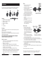
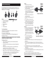
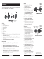
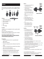
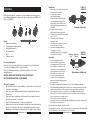
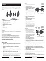
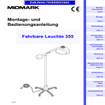
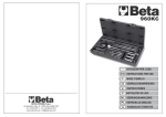
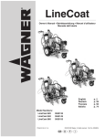
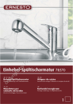
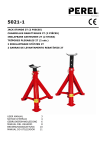
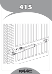
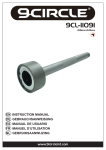
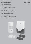
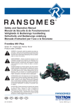
4787
Outils de dépose de rotules
de suspension arrière
- BMW séries 5 et 7
Instructions
Dépose
Remise en place
Distributed by The Tool Connection Ltd
Kineton Road, Southam, Warwickshire CV47 0DR
T +44 (0) 1926 815000 F +44 (0) 1926 815888
[email protected] www.toolconnection.co.uk
Guarantee
If this product fails through faulty materials or workmanship, contact our service
department direct on: +44 (0) 1926 818186. Normal wear and tear are excluded
as are consumable items and abuse.
www.lasertools.co.uk
Instructions
Ces outils ont été conçus pour déposer et remettre en place les rotules de
suspension arrière (douilles) sur les BMW 5 et 7 séries 2.2 (E39/E38)
3
2
4
5
Dépose
FRONT OF
1.
VEHICLE
2.
3.
1
4.
5.
6.
Sommaire
1. Ensemble écrou de compression
2. Manchon de dépose/installation
3. Manchon de dépose
4. Manchon d’installation
5. Ecrou
6. Vis centrale
7.
6
Précautions
Vérifiez que le véhicule est soulevé en toute sécurité et qu’il repose sur des
supports d’essieux.
Portez une protection oculaire appropriée.
Graissez toujours l’écrou, l’ensemble roulements et la barre de compression
avant et après chaque tâche.
NE PAS UTILISER D’OUTILS PNEUMATIQUES AVEC CE PRODUIT.
GRAISSER TOUJOURS LA BARRE FILETEE.
Avant de commencer :
•
A l’aide d’un cric, soulevez l’extrémité arrière du véhicule et faites-le
reposer sur des supports d’essieux.
•
Déposez les roues arrière.
•
N’oubliez pas de marquer l’alignement des rotules existantes.
•
Vérifiez que les flexibles de frein sont maintenus éloignés de la zone de
travail pour ne pas les endommager.
•
Vous aurez besoin de 2 clefs polygonales ou douilles 24 mm.
•
Marquez la position de la rondelle excentrique sur le bras oscillant avant
de dévisser les boulons afin de permettre un repositionnement correct.
Pour accéder à cette rondelle, consultez le manuel d’entretien du
véhicule.
www.lasertools.co.uk
2
8.
Marquez la position de la douille
existante avant la dépose.
Lubrifiez l’écrou, la barre et l’ensemble
roulement de compression.
Déposez l’ensemble bras oscillant pour
avoir accès facilement à la rotule.
Un boulon passant à travers la rotule
sera enlevé au cours de cette opération.
Enlevez le circlip maintenant la rotule.
Assemblez l’outil en utilisant 1, 6, 2, 3, 5.
Assemblez comme indiqué sur le
schéma 1.
Maintenez l’écrou à l’aide d’une clef ou
douille 24 mm.
Serrez lentement l’ensemble roulement
de compression (5) jusqu’à ce que le
manchon de dépose enfonce la rotule
dans le grand manchon.
6
5
2
3
1
Removal of Ball Joint
FRONT OF
Retaining Ball Joint
VEHICLE
Nettoyez l’enveloppe de rotule.
Flange
Nut
Insérez la nouvelle rotule dans le
manchon de pose (4) avant d’assembler
l’outil. La partie en caoutchouc de la
rotule est introduite jusqu’à ce que la
bride repose sur le bord extérieur du
New Ball
4
Joint
manchon.
Faites passer la barre de compression
Replacement of Ball Joint
avec l’écrou de fixation à travers la rotule
et à travers l’enveloppe de la rotule.
Fixez le manchon de dépose/pose (2) et l’ensemble roulement de compression.
Serrez l’ensemble roulement de compression en utilisant une clef ou une douille 24 mm
tout en fixant l’autre extrémité à l’aide d’un outil semblable.
La rotule s’enfoncera dans l’enveloppe dans la direction de l’avant vers l’arrière.
Une fois que la bride de rotule repose contre la face de l’enveloppe (en regardant vers
l’avant du véhicule).
Vérifiez l’alignement à l’équerre.
Remettez en place le circlip et réassemblez la suspension en réalignant sur la position
de la rondelle.
Remise en place
1.
2.
3.
4.
5.
6.
7.
8.
9.
Effectuez l’opération de l’autre côté si nécessaire.
En raison de la nature de l’opération, la barre et l’écrou sont considérés comme des
consommables et ne sont donc pas couverts par la garantie Tool Connection.
www.lasertools.co.uk
3
4787
Extractores de junta de rótula
de suspensión trasera
- BMW Series 5 y 7
Instrucciones
Retirada
Sustitución
Distributed by The Tool Connection Ltd
Kineton Road, Southam, Warwickshire CV47 0DR
T +44 (0) 1926 815000 F +44 (0) 1926 815888
[email protected] www.toolconnection.co.uk
Guarantee
If this product fails through faulty materials or workmanship, contact our service
department direct on: +44 (0) 1926 818186. Normal wear and tear are excluded
as are consumable items and abuse.
www.lasertools.co.uk
Instrucciones
Este juego de herramientas se ha diseñado para extraer y sustituir las juntas
de rótula (casquillos) de la suspensión trasera in situ en los BMW Series 5 y 7
2.2 (E39/E38)
3
2
4
5
Contenido
1. Un conjunto de tuerca de empuje
2. Manguito de extracción/instalación
3. Manguito de extracción
4. Manguito de instalación
5. Tuerca
6. Tornillo central
1
6
Precauciones
Asegúrese de que el vehículo se ha elevado con seguridad y que está
apoyado en soportes de eje.
Lleve protección ocular adecuada.
Engrase siempre la tuerca, el conjunto del cojinete de fuerza y la barra de
fuerza antes y después de cada trabajo.
NO UTILICE HERRAMIENTAS NEUMÁTICAS CON ESTE PRODUCTO.
ENGRASE SIEMPRE LA BARRA ROSCADA.
Antes de empezar
•
Levante con la parte trasera del vehículo y apóyela en soportes de eje.
•
Retire las ruedas traseras.
•
Asegúrese de marcar la alineación de las juntas de rótula existentes.
•
Asegúrese de mantener las mangueras de freno alejadas del área de
trabajo para evitar daños.
•
Necesitará 2 llaves o encastres de corona de 24 mm.
•
Marque la posición de la arandela excéntrica en el brazo oscilante
antes de retirar los pernos para permitir una correcta recolocación. Para
acceder a esta arandela, consulte su manual de servicio de vehículos.
www.lasertools.co.uk
2
Retirada
1. Marque la posición del casquillo
existente antes de la retirada.
2. Lubrique la tuerca, la barra y el
conjunto del cojinete de fuerza.
3. Retire el conjunto del brazo oscilante
para permitir un acceso fácil a la junta
de rótula. En este proceso se retirará un
perno que atraviesa la junta de rótula.
4. Retire el aro de resorte que sujeta la
junta de rótula.
5. Monte la herramienta utilizando 1, 6, 2, 3,
6. Monte como se muestra en el diagrama
7. Sujete la tuerca utilizando una llave o un
adaptador de 24 mm.
8. Apriete el conjunto de cojinete de fuerza
(5) lentamente hasta que el manguito
de extracción empuje la junta de rótula
dentro del manguito grande.
FRONT OF
VEHICLE
6
5
2
3
1
Removal of Ball Joint
Sustitución
FRONT OF
1. Limpie el alojamiento de la junta de
Retaining Ball Joint
VEHICLE
Flange
Nut
rótula
2. Inserte la junta de rótula nueva en el
manguito de instalación (4) antes del
montaje de la herramienta. La parte de
caucho de la junta de rótula se inserta
New Ball
hasta que la brida repose sobre el borde
4
Joint
exterior del manguito.
3. Pase la barra de fuerza con la tuerca de
Replacement of Ball Joint
retención montada a través de la junta
de rótula y a través del alojamiento de la
junta de rótula.
4. Fije el manguito de extracción/instalación (2) y el conjunto del cojinete de fuerza.
5. Apriete el conjunto del cojinete de fuerza utilizando una llave o adaptador de 24 mm
mientras sujeta el otro extremo con una herramienta similar.
6. La junta de rótula se forzará al interior del alojamiento en la dirección de adelante
hacia atrás cuando la brida de la junta de rótula repose contra la cara del alojamiento
(mirando de frente a la parte delantera del vehículo).
7. Compruebe que la alineación está en ángulo recto.
8. Vuelva a colocar el aro de resorte y vuelva a montar la suspensión, realineando la
posición de la arandela.
Realice la tarea en el otro lado si es necesario.
Debido a la naturaleza de la tarea, la tuerca y la barra se consideran como consumibles y,
por lo tanto, no están cubiertas por la garantía de Tool Connection.
www.lasertools.co.uk
3
4787
Kugelgelenk-Abzieher für die
Hinterradaufhängung
- BMW 5 and 7 Series
Gebrauchsanweisung
Ausbau
Ersetzen
Distributed by The Tool Connection Ltd
Kineton Road, Southam, Warwickshire CV47 0DR
T +44 (0) 1926 815000 F +44 (0) 1926 815888
[email protected] www.toolconnection.co.uk
Guarantee
If this product fails through faulty materials or workmanship, contact our service
department direct on: +44 (0) 1926 818186. Normal wear and tear are excluded
as are consumable items and abuse.
www.lasertools.co.uk
Gebrauchsanweisung
Dieser Werkzeugsatz wurde entwickelt zum Abziehen und Ersetzen der
Kugelgelenke (Buchsen) an der Hinterradaufhängung am Fahrzeug für die
BMW Serien 5 & 7 2.2 (E39/E38)
2
3
Inhalt
1. Druckmutterbaugruppe
2. Abzieh-/Monatgehülse
3. Abziehhülse
4. Montagebauhülse
5. Mutter
6. Zentrierschraube
4
5
1
6
Vorsichtsmaßnahmen
Sicherstellen, dass das Fahrzeug sicher angehoben ist und durch
Unterstellböcke abgestützt ist.
Eine geeignete Schutzbrille tragen.
Vor und nach jeder Arbeit immer Mutter, Drucklagerbaugruppe und
Druckstange schmieren.
KEINE DRUCKLUFTWERKZEUGE MIT DIESEM PRODUKT VERWENDEN.
GEWINDESTANGE IMMER SCHMIEREN.
Vor Beginn der Arbeit
•
Heck des Fahrzeugs anheben und mit Achsständern abstützen.
•
Hinterräder entfernen.
•
Sicherstellen, dass die Ausrichtung der vorhandenen Kugelgelenke
markiert ist.
•
Sicherstellen, dass die Bremsschläuche aus dem Arbeitsbereich
ferngehalten werden, um Schäden zu vermeiden.
•
Die benötigen 2 x 24mm Ringschlüssel oder Steckschlüssel
•
Markieren Sie die Position der Exzenterscheibe am Schwenkarm bevor
Sie die Schrauben entfernen, um eine korrekte Neupositionierung
zu ermöglichen. Für den Zugang zu dieser Scheibe, siehe
Wartungshandbuch Ihres Fahrzeugs.
www.lasertools.co.uk
2
Ausbau
1. Markieren Sie die Position der
vorhandenen Buchse vor dem Entfernen.
2. Schmieren Sie Mutter, Stange und
Drucklagerbaugruppe.
3. Entfernen Sie die Schwenkarmbaugruppe
für einen leichten Zugang zum
Kugelgelenk. Bei diesem Vorgang wird
eine Schraube durch das Kugelgelenk
entfernt.
4. Entfernen Sie den Sicherungsring, der
das Kugelgelenk hält.
5. Montieren Sie das Werkzeug mittels 1, 6,
2, 3, 5.
6. Wie in Abbildung 1 gezeigt montieren.
7. Die Mutter mit einem 24 mm-Schraubenschlüssel oder Steckschlüssel halten.
8. Ziehen Sie die Drucklagerbauguppe (5)
langsam an, bis die Abziehhülse das
Kugelgelenk in die große Hülse drückt.
FRONT OF
VEHICLE
6
5
2
3
1
Removal of Ball Joint
FRONT OF
Ersetzen
Retaining Ball Joint
VEHICLE
1. Reinigen Sie das Kugelgelenkgehäuse.
Flange
Nut
2. Setzen Sie das neue Kugelgelenk in
die Montagehülse (4) vor Montage des
Werkzeugs ein. Der Gummiteil des
Kugelgelenks wird eingesetzt bis der
Flansch auf den Außenkanten der Hülse
New Ball
4
ruht.
Joint
3. Führen Sie die Druckstange mit
Replacement of Ball Joint
der montierten Haltemutter durch
das Kugelgelenk und durch das
Kugelgelenkgehäuse.
4. Montieren Sie die Abzieh-/Montagehülse (2) und die Drucklagerbaugruppe. Siehe
Abbildung 2.
5. Ziehen Sie die Drucklagerbaugruppe mit einem 24 mm-Schraubenschlüssel oder
einem Steckschlüssel an, während Sie das andere Ende mit einem ähnliche Werkzeug
halten.
6. Das Kugelgelenk wird von vorne nach hinten in das Gehäuse gedrückt.
7. Wenn der Flansch des Kugelgelenks an der Gehäusefläche anliegt (in Richtung der
Fahrzeugfront).
8. Auf rechtwinkelige Ausrichtung prüfen.
9. Ersetzen Sie den Sicherungsring und montieren Sie die Aufhängung wieder und richten
Sie dabei die Scheibenposition neu aus.
Führen Sie, wenn erforderlich, den Vorgang an der anderen Seite durch.
Aufgrund der Art der Arbeit werden die Mutter und Stange als Verbrauchsmaterial
betrachtet und sind deshalb nicht von der Tool Connection Garantie abgedeckt.
www.lasertools.co.uk
3
4787
Rear Suspension Ball Joint
Removers - BMW 5 and 7 Series
Instructions
Removal
Replacement
Distributed by The Tool Connection Ltd
Kineton Road, Southam, Warwickshire CV47 0DR
T +44 (0) 1926 815000 F +44 (0) 1926 815888
[email protected] www.toolconnection.co.uk
Guarantee
If this product fails through faulty materials or workmanship, contact our service
department direct on: +44 (0) 1926 818186. Normal wear and tear are excluded
as are consumable items and abuse.
www.lasertools.co.uk
Removal
Instructions
This tool kit has been designed to remove and replace the rear suspension ball
joints in situ on BMW 5 and 7 Series 2.2 (E39/E38).
3
2
4
5
Contents
1. Thrust Nut
2. Removing/Installing Sleeve
3. Removing Sleeve
4. Installer Sleeve
5. Nut
6. Centre Screw
1
6
Precautions
•
Make sure the vehicle is securely elevated and supported with axle stands
•
Wear suitable eye protection
•
lways grease the Nut, Force Bearing Assembly and Force Bar before and
after every job
•
DO NOT USE AIR TOOLS WITH THIS PRODUCT
Before you start
•
Jack up the rear end of the vehicle and support with axle stands
•
Remove the rear wheels
•
Make sure you mark the alignment of the existing ball joints
•
Make sure the brake hoses are kept away from the work area to avoid
damage
•
You will need 2 x 24mm Ring Spanners or Sockets
•
Mark the position of the eccentric washer on the swinging arm before
removing the bolts to allow correct re-positioning. For access to this
washer contact your vehicles service manual
www.lasertools.co.uk
2
FRONT OF
VEHICLE
1. Mark the position of the existing
bush prior to removal
2. Lubricate Nut, Bar and Force
Bearing Assembly
3. Remove the swinging arm assembly
to allow easy access to the ball joint.
A bolt passing through the ball joint
will be removed in this process
4. Remove the snap ring holding the ball
joint
5. Assemble the tool using 5, 6, 2, 3, 1
6. Assemble as shown in Diagram 1
7. Hold the Nut using a 24mm spanner or
socket
8. Tighten the Force Bearing Assembly (5)
slowly until the removal sleeve pushes
the ball joint into the large sleeve
Replacement
6
5
3
2
1
Removal of Ball Joint
FRONT OF
Ball Joint
Flange
Retaining
Nut
1. Clean the ball joint housing
2. Insert the new ball joint into the
Installer Sleeve (4) prior to assembly
of tool. The rubber part of the ball joint
is inserted until the flange rests on the
outer edge of the sleeve
3. Pass the Force Bar with the retaining
nut fitted through the ball joint and
through the ball joint housing
4. Attach the Removing/Installing Sleeve (2)
and Force Bearing Assembly (1)
5. Tighten the Force Bearing Assembly
using a 24mm spanner or socket whilst
securing the other end with a similar tool
6. The ball joint will be forced into the
housing in the direction of front to back
7. When the flange of the ball joint rests
against the face of the housing (facing
the front of the vehicle)
8. Check for square alignment
9. Replace the snap ring and re-assemble
the suspension, re-aligning the washer
position
4
VEHICLE
New Ball
Joint
Replacement of Ball Joint
Perform task on the
other side if necessary
www.lasertools.co.uk
3
4787
Extractores de rótulas esféricas
da suspensão traseira
- BMW séries 5 e 7
Istruzioni
Rimozione
Installazione
Distributed by The Tool Connection Ltd
Kineton Road, Southam, Warwickshire CV47 0DR
T +44 (0) 1926 815000 F +44 (0) 1926 815888
[email protected] www.toolconnection.co.uk
Guarantee
If this product fails through faulty materials or workmanship, contact our service
department direct on: +44 (0) 1926 818186. Normal wear and tear are excluded
as are consumable items and abuse.
www.lasertools.co.uk
Istruzioni
Questo kit di attrezzi è stato progettato per estrarre e sostituire i giunti sferici
(boccole) delle sospensioni posteriori in sede sulle serie BMW 5 & 7 2.2 (E39/
2
E38)
4
3
5
Rimozione
FRONT OF
1.
VEHICLE
2.
3.
1
4.
Contenuto
1. Complessivo dado a pressione
2. Manicotto di montaggio/rimozione
3. Manicotto di rimozione
4. Manicotto di montaggio
5. Dado
6. Vite di centraggio
6
Precauzioni
Assicurarsi che il veicolo sia adeguatamente sollevato e supportato mediante i
supporti semiasse.
Indossare una protezione adeguata per gli occhi.
Lubrificare sempre il dado, il complessivo cuscinetto a pressione e la barra di
pressione prima e dopo qualsiasi intervento di lavoro.
NON UTILIZZARE ATTREZZI PNEUMATICI CON QUESTO PRODOTTO.
LUBRIFICARE SEMPRE LA BARRA FILETTATA.
Prima di iniziare
•
Sollevare l’estremità posteriore del veicolo e supportarla mediante i
supporti semiasse.
•
Rimuovere le ruote posteriori.
•
Assicurarsi di contrassegnare la posizione di allineamento dei giunti sferici
esistenti.
•
Assicurarsi che i tubi flessibili dei freni siano mantenuti lontano dall’area di
lavoro, in modo da evitare qualsiasi danno.
•
Occorrono chiavi a stella o chiavi a tubo da 2 x 24 mm.
•
Prima di rimuovere i bulloni contrassegnare la posizione della rondella
eccentrica sul braccio oscillante in modo da consentire un corretto
riposizionamento. Per accedere a questa rondella fare riferimento al
manuale d’officina del veicolo.
www.lasertools.co.uk
2
5.
6.
7.
8.
Contrassegnare la posizione della boccola
esistente prima di rimuoverla.
Lubrificare dado, barra e complessivo
cuscinetto a pressione.
Rimuovere il complessivo braccio
oscillante per accedere facilmente al
giunto sferico. Durante questa fase verrà
rimosso un bullone che attraversa il giunto
sferico.
Rimuovere l’anello elastico che fissa il
giunto sferico.
Montare l’attrezzo usando 1, 6, 2, 3, 5.
Eseguire il montaggio secondo lo schema
Tenere fermo il dado utilizzando una
chiave a stella o una chiave a tubo da 24
mm.
Serrare il complessivo cuscinetto a
pressione (5) lentamente fino a che il
manicotto di rimozione non spinge il
giunto sferico nel manicotto largo.
Installazione
1.
2.
3.
4.
5.
6.
7.
8.
9.
6
5
3
2
1
Removal of Ball Joint
FRONT OF
Retaining
Nut
Ball Joint
Flange
VEHICLE
Pulire l’alloggiamento del giunto sferico.
Inserire il nuovo giunto sferico nel
manicotto di montaggio (4) prima di
montare l’attrezzo. La parte in gomma
New Ball
4
Joint
del giunto sferico deve essere inserita fino
a quando la flangia non tocca il bordo
Replacement of Ball Joint
esterno del manicotto.
Far passare la barra di pressione con
il dado di ritegno installato attraverso il
giunto sferico e il relativo alloggiamento.
Attaccare il manicotto di montaggio/rimozione (2) e il complessivo cuscinetto a
pressione. Fare riferimento allo schema 2.
Serrare il complessivo cuscinetto a pressione usando una chiave a stella o una chiave a
tubo da 24 mm e fissare l’altra estremità con un attrezzo simile.
Il giunto sferico verrà spinto a forza nell’alloggiamento in direzione avanti verso dietro.
La flangia del giunto sferico tocca la superficie dell’alloggiamento
(quella rivolta verso la parte anteriore del veicolo).
Verificare l’allineamento.
Riposizionare l’anello elastico e riassemblare le sospensioni riallineando la rondella.
Se necessario, effettuare l’operazione sull’altro lato.
Data la natura dell’intervento e degli attrezzi, dado e barra sono considerati materiali
consumabili e pertanto non sono coperti dalla garanzia Tool Connection.
www.lasertools.co.uk
3
4787
Verwijderaars voor het
achterwielophangingskogelgewricht
- BMW 5 & 7 Series
instructies
Verwijdering
Vervanging
Distributed by The Tool Connection Ltd
Kineton Road, Southam, Warwickshire CV47 0DR
T +44 (0) 1926 815000 F +44 (0) 1926 815888
[email protected] www.toolconnection.co.uk
Guarantee
If this product fails through faulty materials or workmanship, contact our service
department direct on: +44 (0) 1926 818186. Normal wear and tear are excluded
as are consumable items and abuse.
www.lasertools.co.uk
instructies
Deze gereedschapsset is ontworpen voor het verwijderen en vervangen van
de achterwielophangingskogelgewrichten (bussen) aanwezig in de BMW 5 & 7
Series 2.2 (E39/E38)
3
2
4
5
Inhoud
1. Drukmoerassemblage
2. Verwijderings/montagemanchet
3. Verwijderingsmanchet
4. Montagemanchet
5. Moer
6. Centrale schroef
1
6
Voorzorgsmaatregelen
Controleer of het voertuig veilig omhoog is gebracht en wordt ondersteund
door assteunen Draag geschikte oogbescherming
De moer, krachtlagerassemblage en krachtstang altijd vóór en na elke
opdracht smeren
GEBRUIK GEEN LUCHTGEREEDSCHAP BIJ DIT PRODUCT
DE SCHROEFDRAADSTANG ALTIJD SMEREN
Alvorens te beginnen
•
De achterkant van het voertuig opkrikken en ondersteunen met assteunen
•
Verwijder de achterwielen
•
Zorg ervoor dat de uitlijning van de bestaande kogelgewrichten worden
gemarkeerd
•
Zorg ervoor dat de remslangen uit de buurt van het werkgebied worden
gehouden om schade te voorkomen.
•
U zult 2 x 24 mm ringsleutels of inbussen nodig hebben
•
Markeer de positie van de excentrische sluitring op de zwenkarm alvorens
de bouten te verwijderen om correcte terugplaatsing mogelijk te maken.
Raadpleeg uw voertuigservicehandleiding voor toegang tot deze sluitring.
www.lasertools.co.uk
2
Verwijdering
FRONT OF
1. Markeer de positie van de bestaande bus
VEHICLE
alvorens hem te verwijderen
2. Smeer de moer, stang en
krachtlagerassemblage
3. Verwijder de zwenkarmassemblage
voor gemakkelijke toegang tot het
6
5
kogelgewricht. Een bout die door het
1
3
2
kogelgewricht gaat wordt in dit proces
Removal
of
Ball
Joint
verwijderd
4. Verwijder de veerring die het
kogelgewricht op zijn plaats houdt
5. Assembleer het gereedschap met behulp
van 1, 6, 2, 3, 5.
6. Assembleer op de in Diagram 1
aangegeven wijze
7. Houd de moer vast met behulp van een
24 mm moersleutel of inbus
8. Draai de krachtlagerassemblage
(5) langzaam vast tot de
verwijderingsmanchet het kogelgewricht
FRONT OF
in de grote manchet duwt
Retaining Ball Joint
VEHICLE
Flange
Nut
Vervanging
1. Reinig het kogelgewrichthuis
2. Steek het nieuwe kogelgewricht in
de montagemanchet (4) alvorens het
gereedschap te assembleren. Het
New Ball
4
rubberen deel van het kogelgewricht
Joint
wordt ingestoken tot de flens op de
Replacement of Ball Joint
buitenrand van de manchet rust.
3. Passeer de krachtstang met de
borgmoer door het kogelgewricht
gemonteerd en door de behuizing van
het kogelgewricht.
4. Bevestig de verwijderings/montagemanchet (2) en de krachtlagerassemblage.
5. Draai de krachtlagerassemblage met behulp van een 24 mm moersleutel of inbus vast
terwijl het andere uiteinde wordt vastgezet met een soortgelijk stuk gereedschap
6. Het kogelgewricht zal van voor naar achter in de behuizing worden geforceerd
7. Wanneer de flens van het kogelgewricht tegen het oppervlak van de behuizing rust
(op de voorkant van het voertuig gericht).
8. Controleer op rechthoekige uitlijning.
9. Vervang de veerring en assembleer de wielophanging opnieuw, waarbij de positie van
de sluitring in lijn wordt gebracht.
Voer de taak indien nodig aan de andere kant uit
In verband met de aard van de taak worden de moer en stang gezien als verbruiksgoederen
en vallen daarom niet onder de garantie van Tool Connection.
www.lasertools.co.uk
3
4787
Extractores de rótulas esféricas
da suspensão traseira
- BMW séries 5 e 7
Instruções
Remoção
Substituição
Distributed by The Tool Connection Ltd
Kineton Road, Southam, Warwickshire CV47 0DR
T +44 (0) 1926 815000 F +44 (0) 1926 815888
[email protected] www.toolconnection.co.uk
Guarantee
If this product fails through faulty materials or workmanship, contact our service
department direct on: +44 (0) 1926 818186. Normal wear and tear are excluded
as are consumable items and abuse.
www.lasertools.co.uk
Instruções
Este kit de ferramentas foi desenvolvido para remover e substituir as rótulas
esféricas (casquilhos) da suspensão traseira in situ nos BMW séries 5 e 7 2.2
2
(E39/E38)
4
3
5
Conteúdo
1. Unidade da porca de encosto
2. Manga de remoção/instalação
3. Manga de remoção
4. Manga da ferramenta de instalação
5. Porca
6. Parafuso central
1
6
Precauções
Certifique-se de que o veículo é levantado e apoiado em segurança em apoios
de eixos
Use óculos de protecção adequados
Antes e depois de cada trabalho lubrifique sempre a porca, unidade de
suporte da ferramenta do casquilho de suspensão e barra de suporte
NÃO UTILIZE FERRAMENTAS PNEUMÁTICAS COM ESTE PRODUTO
LUBRIFIQUE SEMPRE A BARRA ROSCADA
Antes de começar
•
Levante com o macaco a traseira do veículo e apoie em apoios de eixos
•
Retire as rodas traseiras
•
Certifique-se de que assinala o alinhamento das rótulas esféricas
existentes
•
Certifique-se de que os tubos flexíveis do travão são mantidos afastados
da área de trabalho para evitar danos.
•
Serão necessárias 2 chaves de estrias ou de caixa de 24 mm
•
Assinale a posição da anilha excêntrica no braço oscilante antes de retirar
os parafusos de modo a permitir o correcto reposicionamento. Para
aceder a esta anilha, consulte o manual de assistência do seu veículo.
www.lasertools.co.uk
2
Remoção
1. Assinale a posição do casquilho existente
antes de proceder à remoção
2. Lubrifique a porca, a barra e a unidade de
suporte da ferramenta do casquilho de
suspensão
3. Remova a unidade do braço oscilante
para permitir um fácil acesso à rótula
esférica. Neste processo, será necessário
retirar um parafuso que atravessa a rótula
esférica
4. Retire o anel de aperto que fixa a rótula
esférica
5. Monte a ferramenta utilizando 1, 6, 2, 3, 6.
Monte conforme se ilustra
7. Segure a porca utilizando uma chave de
bocas ou de caixa
8. Aperte lentamente a unidade de suporte
da ferramenta do casquilho de suspensão
(5) até a manga de remoção empurrar a
rótula esférica para a manga grande
FRONT OF
VEHICLE
5
6
2
3
1
Removal of Ball Joint
FRONT OF
Retaining Ball Joint
VEHICLE
Substituição
Flange
Nut
1. Limpe o invólucro da rótula esférica
2. Antes de montar a ferramenta, insira
a nova rótula esférica na manga da
ferramenta de instalação (4). A parte em
borracha da rótula esférica é inserida até
New Ball
4
Joint
a flange ficar pousada sobre o rebordo
exterior da manga.
Replacement of Ball Joint
3. Passe a barra de força com a porca de
bloqueio instalada pela rótula esférica e
pelo invólucro da rótula esférica.
4. Fixe a manga de remoção/instalação (2) e a unidade de suporte da ferramenta do
casquilho de suspensão.
5. Aperte unidade de suporte da ferramenta do casquilho de suspensão com uma chave
de bocas ou de caixa de 24 mm enquanto segura a outra extremidade com uma
ferramenta idêntica
6. A rótula esférica será forçada para o invólucro na direcção da frente para trás
7. Quando a flange da rótula esférica ficar encostada à superfície do invólucro (virada
para a frente do veículo).
8. Confirme um alinhamento em esquadria.
9. Instale novamente o anel de aperto e monte novamente a suspensão, realinhando a
posição da anilha.
Se necessário, realize a tarefa do lado oposto
Devido à natureza da tarefa, a porca e a barra fresas são consideradas consumíveis, pelo
que não são abrangidas pela garantia da Tool Connection.
www.lasertools.co.uk
3