1
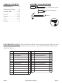
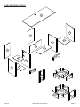
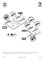
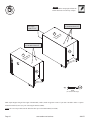
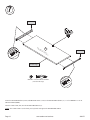
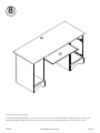
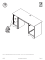
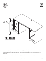
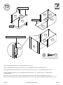
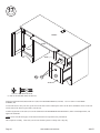
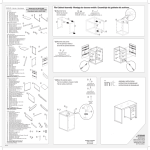
402375
Computer Desk
PLEASE CONTACT US
BEFORE RETURNING
YOUR UNIT TO THE STORE
1-800-523-3987
www.sauder.com
NOTE: THIS INSTRUCTION BOOKLET CONTAINS
IMPORTANT SAFETY INFORMATION.
PLEASE READ AND KEEP FOR FUTURE REFERENCE.
English .................... Page 1-22
Français ...............Pages 23-25
Made in the USA
Archbold, OH
Espanol.............Páginas 26-28
Lot #: 345251
05 / 02 / 12
Date Purchased: ____________________
TABLE OF CONTENTS
ASSEMBLY TOOLS REQUIRED
Part Identification ................... 2-3
No. 2 Phillips Screwdriver
Hardware Identification ......... 4-5
Tip Shown Actual Size
Assembly Steps .................... 6-22
Français .............................. 23-25
Hammer
Espanol............................... 26-28
Safety ................................. 29-30
Warranty ...................................31
PART IDENTIFICATION: While not all parts are labeled, some of the parts will have a label or an inked
letter on the edge to help distinguish similar parts from each other. Use this PART IDENTIFICATION to help
identify similar parts.
Page 2
A2
RIGHT END
1
M
DOOR
1
B
LEFT END
1
N
LARGE DRAWER FRONT
1
C2
RIGHT UPRIGHT
1
D227 LARGE DRAWER BACK
1
D
LEFT UPRIGHT
1
D232 LARGE DRAWER SIDE
2
E
TOP
1
D793 LARGE DRAWER BOTTOM
1
F
MODESTY PANEL
1
G2
RIGHT BOTTOM
1
D230 SMALL DRAWER BACK
1
H
LEFT BOTTOM
1
D231 SMALL DRAWER SIDE
2
I
RIGHT BACK
1
D792 SMALL DRAWER BOTTOM
1
J
LEFT BACK
1
V2
RIGHT BASE
1
K
ADJUSTABLE SHELF
1
W
LEFT BASE
1
L
KEYBOARD SHELF
1
R
SMALL DRAWER FRONT
www.sauder.com/services
1
402375
PART IDENTIFICATION
E
A2
I
G2
C2
F
L
J
V2
K
D
B
H
D231
D230
W
D792
M
R
D231
13-1/2"
D232
D227
D793
D232
N
14-1/8"
402375
www.sauder.com/services
Page 3
HARDWARE IDENTIFICATION
35AW
CABINET RIGHT - 1 35AX CABINET LEFT - 1
35AY
35DA
CABINET RIGHT - 1 35DB CABINET LEFT - 1
35DC DRAWER RIGHT - 1 35DD
45BA
CABINET RIGHT - 1 45BB CABINET LEFT - 1
45BC
JJ FILE GLIDE - 2
MM2 HIDDEN CAM - 16
Page 4
DRAWER RIGHT - 1 35AZ DRAWER LEFT - 1
DRAWER RIGHT - 1 45BD DRAWER LEFT - 1
KK FILE ROD - 2
NN2
DRAWER LEFT - 1
CAM DOWEL - 16
www.sauder.com/services
LL ANGLE BRACKET - 8
OO CORD CLIP - 1
402375
HARDWARE IDENTIFICATION
PP HINGE BRACKET - 2
TT
LARGE DRAWER
FRONT BRACKET - 2
QQ HINGE - 2
UU
SMALL DRAWER
FRONT BRACKET - 1
XX FELT DISC CARD - 1
RR BACKPLATE - 3
VV GROMMET - 1
YY METAL PIN - 4
SS PULL - 3
WW GROMMET CAP - 1
ZZ RUBBER SLEEVE - 4
AAA BLACK 1-7/8" FLAT HEAD SCREW - 4
BBB
BROWN 1" FLAT HEAD SCREW - 4
GOLD 1" MACHINE SCREW - 3
DDD
BLACK 9/16" LARGE HEAD SCREW - 20
BLACK 1/2" FLAT HEAD SCREW - 4
FFF
BROWN 7/16" LARGE HEAD SCREW - 4
III
EEE
GGG GOLD 5/16" FLAT HEAD SCREW - 20
HHH NAIL - 29
Screws are shown actual size. You may receive extra hardware with your unit.
402375
www.sauder.com/services
Page 5
S
p
te
Look for this icon. It means a video
assembly tip is available at:
www.sauder.com/services/tips
1
Do not tighten the HIDDEN CAMS in this step.
B
A2
D
C2
H
Arrow
MM2
G2
(16 used)
NN2
Arrow
Insert the metal end of the CAM
DOWEL into the HIDDEN CAM.
Assemble your unit on a carpeted floor or on the empty carton to avoid scratching your unit or the floor.
Push sixteen HIDDEN CAMS (MM2) into the ENDS (A2 and B), UPRIGHTS (C2 and D), and BOTTOMS (G2 and H). Then, insert
the metal end of a CAM DOWEL (NN2) into each HIDDEN CAM.
Page 6
www.sauder.com/services
402375
S
p
te
2
Roller end
A2
D
Roller end
Roller end
C2
GGG
GOLD 5/16" FLAT HEAD SCREW
(12 used in this step)
Roller end
Fasten the CABINET RIGHTS (35AW, 35DA, and 45BA) and CABINET LEFTS (35AX, 35DB and 45BB) to the RIGHT
END (A2) and UPRIGHTS (C2 and D). Use twelve GOLD 5/16” FLAT HEAD SCREWS (GGG).
402375
www.sauder.com/services
Page 7
S
p
te
3
Caution
Do not stand the unit upright without the
BACK fastened. The unit may collapse.
Roller end
Roller end
A2
C2
G2
D
This hole must be here.
H
B
This hole must be here.
Fasten the ENDS (A2 and B) and UPRIGHTS (C2 and D) to the BOTTOMS (G2 and H). Tighten eight HIDDEN CAMS.
Caution
Risk of damage or
injury. Hidden Cams
must be completely
tightened. Hidden
Cams that are not
completely tightened
may loosen, and parts
may separate.
To completely tighten:
Page 8
Start
Arrow
Tighten
Maximum
210 degrees
Arrow
Minimum
190 degrees
www.sauder.com/services
402375
S
p
te
4
V2
A2
C2
G2
W
D
B
H
LL
LL
LL
DDD
BLACK 9/16" LARGE HEAD SCREW
(12 used for the ANGLE BRACKETS)
Fasten six ANGLE BRACKETS (LL) to the ENDS (A2 and B), UPRIGHTS (C2 and D), and BOTTOMS (G2 and H). Use six
BLACK 9/16” LARGE HEAD SCREWS (DDD).
NOTE: Be sure the edges of the ANGLE BRACKETS are even with the edges of the ENDS, UPRIGHTS, and BOTTOMS.
Fasten the BASES (V2 and W) to the ENDS (A2 and B), UPRIGHTS (C2 and D), and BOTTOMS (G2 and H). Use six BLACK
9/16” LARGE HEAD SCREWS (DDD).
402375
www.sauder.com/services
Page 9
S
p
te
Caution
Do not stand the unit upright without the
BACK fastened. The unit may collapse.
5
These holes must line up
over the BOTTOM (G2).
These edges
should be even.
F
su in
rf ish
ac e
e d
I
These holes must line up
over the BOTTOM (H).
G2
F
su in
rf ish
ac e
e d
J
H
HHH
NAIL
(29 used in this step)
Make equal margins along all four edges of the BACKS (I and J). Push on opposite corners of your unit if needed to make it “square”.
Fasten the BACKS (I and J) to your unit using the NAILS (HHH).
NOTE: Be sure to tap NAILS into the holes that line up over the BOTTOMS (G2 and H).
Page 10
www.sauder.com/services
402375
S
p
te
6
AAA
BLACK 1-7/8" FLAT HEAD SCREW
(4 used for the MODESTY PANEL)
This hole must
be here.
B
D
C2
F
A2
E
LL
FFF
BROWN 7/16" LARGE HEAD SCREW
(4 used for the ANGLE BRACKETS)
Maximum
210 degrees
Arrow
Minimum
190 degrees
Fasten the ENDS (A2 and B) and UPRIGHTS (C2 and D) to the TOP (E). Tighten eight HIDDEN CAMS.
Fasten the MODESTY PANEL (F) to the UPRIGHTS (C2 and D). Use four BLACK 1- 7/8” FLAT HEAD SCREWS (AAA).
Now, fasten two ANGLE BRACKETS (LL) to the TOP (E) and MODESTY PANEL (F). Use four BROWN 7/16” LARGE HEAD
SCREWS (FFF).
402375
www.sauder.com/services
Page 11
S
p
te
7
Roller end
OO
is
in
F
L
d
he
Roller end
e
ac
rf
su
Finished edge
BBB
BROWN 1" FLAT HEAD SCREW
(4 used in this step)
Fasten the DRAWER RIGHT (35AY) and DRAWER LEFT (35AZ) to the KEYBOARD SHELF (L). Use four BROWN 1” FLAT
HEAD SCREWS (BBB).
Turn the CORD CLIP (OO) into the KEYBOARD SHELF (L).
NOTE: The CORD CLIP is used to hold your keyboard cord against the KEYBOARD SHELF.
Page 12
www.sauder.com/services
402375
S
p
te
8
L
Carefully stand your unit upright.
To insert the KEYBOARD SHELF (L) into your unit, tip the front of the KEYBOARD SHELF down and drop the rollers on the
KEYBOARD SHELF behind the rollers on the unit. Lift the front of the KEYBOARD SHELF up and slide it into the unit.
402375
www.sauder.com/services
Page 13
S
p
te
9
Adjusting
screw
Mounting
screw
(vertical adjustment)
QQ
M
EEE
BLACK 1/2" FLAT HEAD SCREW
(4 used in this step)
To separate the HINGES (QQ) from the HINGE BRACKETS (PP), turn the mounting screw counter- clockwise and the adjusting
screw clockwise. Follow the diagram closely.
Fasten two HINGES (QQ) to the DOOR (M). Use four BLACK 1/2” FLAT HEAD SCREWS (EEE).
Page 14
www.sauder.com/services
402375
S
p
te
10
B
PP
Fasten two HINGE BRACKETS (PP) to the LEFT END (B). Use the screws in the HINGE BRACKETS.
402375
www.sauder.com/services
Page 15
S
p
te
11
XX
RR + SS
B
M
XX
III
GOLD 1" MACHINE SCREW
(1 used for the BACKPLATE and PULL)
Fasten the DOOR (M) to the LEFT END (B). Slide the HINGES (QQ) onto the HINGE BRACKETS on the LEFT END. Secure the
DOOR with the mounting screw on the HINGE BRACKET. See the next step for adjustments.
Peel the FELT DISC from the FELT DISC CARD (XX). Stick a FELT DISC on the DOOR where it comes in contact with the
UPRIGHT (D).
Fasten a BACKPLATE (RR) and PULL (SS) to the DOOR (M). Use a GOLD 1” MACHINE SCREW (III).
Page 16
www.sauder.com/services
402375
S
p
te
12
Adjusting screw
(horizontal)
Mounting screw
(depth))
(vertical adjustment)
Refer to the enlarged diagram to identify the parts on the HINGES and HINGE BRACKETS.
The DOOR may need some adjustments. Follow the text below to make needed adjustments.
DOOR ADJUSTMENTS:
To adjust the DOOR from side to side (horizontal), loosen the mounting screw several turns, then turn the adjusting screw in or out.
Tighten the mounting screw after making adjustments.
To adjust the DOOR up and down (vertical), loosen both screws that fasten the HINGE BRACKETS to the END. Move the DOOR
up or down to the desired location. Tighten the screws after making adjustments.
To adjust the DOOR in or out (depth), loosen the mounting screw one turn and move the DOOR in or out, as needed. Tighten the
mounting screw after making adjustments.
402375
www.sauder.com/services
Page 17
S
p
te
13
Slide the SIDES down.
D232
D232
D227
D227
D232
Finished surface
D232
14-1/8"
Groove
D793
D232
Tap down with your screwdriver and hammer.
D793
D232
N
D232
TT
DDD
BLACK 9/16" LARGE HEAD SCREW
(8 used for the DRAWER FRONTS)
Slide the DRAWER SIDES (D232) onto the DRAWER BACK (D227).
Slide the DRAWER BOTTOM (D793) into the grooves in the DRAWER SIDES and DRAWER BACK.
Pull the DRAWER FRONT BRACKETS (TT) apart and slide them into the grooves in the DRAWER SIDES (D232).
Fasten the DRAWER FRONT (N) to the DRAWER FRONT BRACKETS. Use eight BLACK 9/16” LARGE HEAD
SCREWS (DDD).
Repeat this step for the small drawer using the SMALL DRAWER FRONT (R), SMALL DRAWER BACK (D230),
SMALL DRAWER SIDES (D231), SMALL DRAWER BOTTOM (D792), and SMALL DRAWER FRONT BRACKETS (UU).
Page 18
www.sauder.com/services
402375
S
p
te
14
Roller end
1
2
4
3
D232
Roller end
D232
1
2
4
3
GGG
GOLD 5/16" FLAT HEAD SCREW
(8 used in this step)
Fasten the DRAWER RIGHT (45BC) and DRAWER LEFT (45BD) to the DRAWER SIDES (D232). Use four GOLD 5/16” FLAT
HEAD SCREWS (GGG) through holes #2 and #4.
Repeat this step for the small drawer using holes #1 and #3 on the DRAWER RIGHT (35DC) and DRAWER LEFT (35DD).
402375
www.sauder.com/services
Page 19
S
p
te
15
Insert the FILE RODS into the holes of your choice
in the FILE GLIDES, depending on your file sizes.
KK
JJ
D232
JJ
D232
Push a FILE GLIDE (JJ) onto the DRAWER SIDE (D232).
Slide the FILE RODS (KK) into the FILE GLIDE (JJ) on the DRAWER SIDE.
Slide another FILE GLIDE (JJ) onto the other end of the FILE RODS (KK), then press this FILE GLIDE over the other
DRAWER SIDE (D232).
Page 20
www.sauder.com/services
402375
S
p
te
16
WW
VV
K
E
B
D
YY
ZZ
Push the RUBBER SLEEVES (ZZ) over the METAL PINS (YY). Insert the METAL PINS into the hole locations of your
choice in the LEFT END (B) and LEFT UPRIGHT (D). Set the ADJUSTABLE SHELF (K) onto the METAL PINS.
Insert the GROMMET (VV) and GROMMET CAP (WW) into the hole in the TOP (E).
402375
www.sauder.com/services
Page 21
S
p
te
17
100 lbs.
25 lbs.
50 lbs.
10 lbs.
R
N
RR + SS
35 lbs.
III
GOLD 1" MACHINE SCREW
(2 used for the BACKPLATES and PULLS)
Fasten the BACKPLATES (RR) and PULLS (SS) to the DRAWER FRONTS (N and R). Use two GOLD 1” MACHINE
SCREWS (III).
To insert the drawers into your unit, tip the front of the drawer down and drop the rollers on the drawer behind the rollers on the unit.
Lift the front of the drawer up and slide it into the unit.
To make adjustments to the drawer, loosen the SCREWS in the DRAWER FRONT BRACKETS, make needed adjustments, and
tighten the SCREWS.
NOTE: Please read the back pages of the instruction booklet for important safety information.
This completes assembly. Clean with your favorite furniture polish or a damp cloth. Wipe dry.
Page 22
www.sauder.com/services
402375
402375
Utilisez les instructions d’assemblage en français avec
les schémas étape par étape du manuel d’instruction
en anglais. Chaque étape en français correspond à la
même étape en anglais. La pièce devant être attachée
à l’élément est représentée en gris sur les schémas de
chaque étape pour plus de précision. Comparer la “Liste
de pièces” ci-dessous avec la “PART IDENTIFICATION”
du manuel en anglais pour vous familiariser avec les
pièces avant l’assemblage.
REMARQUE : CE MANUEL D’INSTRUCTIONS
CONTIENT D’IMPORTANTES INFORMATIONS
RELATIVES À LA SÉCURITÉ. À LIRE ET CONSERVER
POUR TOUTE RÉFÉRENCE FUTURE.
Bureau d’Ordinateur
NOUS SOMMES LA POUR VOUS AIDER!
Nous faisons de notre mieux pour nous assurer que
votre meuble arrive dans d’excellentes conditions. Nos
représentants du service Clientèle sont aimables et prêts
à vous aider au cas où une pièce aurait été endommagée
ou manquerait (ou si vous aviez besoin d’aide pour
l’assemblage). NE RAMENEZ PAS LE MEUBLE AU
MAGASIN. Au Canada, composez ce numéro d’appel gratuit:
1-800-523-3987
Du lundi au vendredi, de 9 heures du matin à
5:30 heures du soir (horaire Côte Est)
(sauf jours fériés)
Si une pièce a besoin d’être remplacée, la pièce de
remplacement sera envoyée dans les 48 heures. (Sauf
week-ends et jours fériés)
LISTE DE PIÈCES
REFERENCE DESCRIPTION
A l’usage exclusif du
Canada Noter la date
d’achat de cet élément
et conserver le livret
pour future référence.
Pour contacter Sauder
en ce qui concerne cet
élément, faire référence
au numéro de lot et
numéro de modèle en
appelant notre numéro
sans frais.
Lot nº : ____________
QUANTITÉ
A2 EXTRÉMITÉ DROITE ......................1
B
EXTRÉMITÉ GAUCHE ....................1
C2 MONTANT DROIT............................1
D
MONTANT GAUCHE .......................1
E
DESSUS ..........................................1
F
VOILE DE FOND .............................1
G2 DESSOUS DROIT ...........................1
H
DESSOUS GAUCHE .......................1
I
ARRIÈRE DROIT .............................1
J
ARRIÈRE GAUCHE .........................1
K
TABLETTE RÉGLABLE ...................1
L
TABLETTE DE CLAVIER .................1
M
PORTE .............................................1
N
DEVANT DE GRAND TIROIR ..........1
D227 ARRIÈRE DE GRAND TIROIR .......1
D232 CÔTÉ DE GRAND TIROIR .............2
D793 FOND DE GRAND TIROIR .............1
R
DEVANT DE PETIT TIROIR.............1
D230 ARRIÈRE DE PETIT TIROIR ..........1
D231 CÔTÉ DE PETIT TIROIR ................2
D792 FOND DE PETIT TIROIR ................1
V2 SOCLE DROIT .................................1
W SOCLE GAUCHE ............................1
35AW ÉLÉMENT DROITE........................1
35AX ÉLÉMENT GAUCHE.......................1
35AY TIROIR DROIT ................................1
35AZ TIROIR GAUCHE............................1
35DA ÉLÉMENT DROITE ........................1
35DB ÉLÉMENT GAUCHE ......................1
35DC TIROIR DROIT ...............................1
35DD TIROIR GAUCHE ...........................1
LISTE DE PIÈCES
REFERENCE DESCRIPTION
QUANTITÉ
45BA ÉLÉMENT DROITE.........................1
45BB ÉLÉMENT GAUCHE.......................1
45BC TIROIR DROIT ...............................1
45BD TIROIR GAUCHE ...........................1
JJ ARMATURE POUR DOSSIERS .....2
KK GUIDE POUR DOSSIERS ...............2
LL CONSOLE À ÉQUERRE .................8
MM2 EXCENTRIQUE ESCAMOTABLE .16
NN2 CHEVILLE D’EXCENTRIQUE ........16
OO CLIP DE CORDON ..........................1
PP CONSOLE DE CHARNIÈRE ...........2
QQ CHARNIÈRE ....................................2
RR FERRURE ........................................3
SS POIGNÉE .........................................3
TT CONSOLE DE DEVANT
DE GRAND TIROIR .........................2
UU CONSOLE DE DEVANT
DE PETIT TIROIR ............................1
VV PASSE--CÂBLES .............................1
WW COUVERCLE DE PASSE--CÂBLES .. 1
XX FICHE DE TAMPONS EN FEUTRE ... 1
YY GOUPILLE EN MÉTAL ....................... 4
ZZ MANCHON EN CAOUTCHOUC ........ 4
AAA VIS NOIRE TÊTE PLATE 48 mm ....... 4
BBB VIS MARRON TÊTE PLATE 25 mm .. 4
III
VIS DORÉE À MÉTAUX 25 mm ......... 3
DDD VIS NOIRE TÊTE LARGE 14 mm .... 20
EEE VIS NOIRE TÊTE PLATE 13 mm ....... 4
FFF VIS MARRON TÊTE LARGE 11 mm .. 4
GGG VIS DORÉE TÊTE PLATE 8 mm ...... 20
HHH CLOU................................................ 29
Date de
l’achat: ____________
402375
www.sauder.com/services
Page 23
ÉTAPE 1
ÉTAPE 6
Assembler l’élément sur un sol àmoquette ou sur le
carton vide pour éviter d’endommager l’élément ou le
sol.
Fixer les EXTRÉMITÉS (A2 et B) et les
MONTANTS (C2 et D) au DESSUS (E). Serrer huit
EXCENTRIQUES ESCAMOTABLES.
Enfoncer seize EXCENTRIQUES ESCAMOTABLES (MM2)
dans les EXTRÉMITÉS (A2 et B), les MONTANTS (C2
et D) et les DESSOUS (G2 et H). Ensuite, insérer l'extrémité
en métal de la CHEVILLE D’EXCENTRIQUE (NN2) dans
chaque EXCENTRIQUE ESCAMOTABLE.
Fixer le VOILE DE FOND (F) aux MONTANTS (C2 et D).
Utiliser quatre VIS NOIRES TÊTE PLATE 48 mm (AAA).
ÉTAPE 2
ÉTAPE 7
Fixer les GLISSIÈRES DROITS D’ÉLÉMENT (35AW,
35DA et 45BA) et les GLISSIÈRES GAUCHES
D’ÉLÉMENT (35AX, 35DB et 45BB) sur l’EXTRÉMITÉ
DROITE (A2) et les MONTANTS (C2 et D). Utiliser
douze VIS DORÉES TÊTE PLATE 8 mm (GGG).
Fixer le TIROIR DROIT (35AY) et le TIROIR GAUCHE (35AZ)
à la TABLETTE DE CLAVIER (L). Utiliser quatre VIS MARRON
TÊTE PLATE 25 mm (BBB).
ÉTAPE 3
Fixer les EXTRÉMITÉS (A2 et B) et les
MONTANTS (C2 et D) aux DESSOUS (G2 et H). Serrer
huit EXCENTRIQUES ESCAMOTABLES.
ÉTAPE 4
Fixer six CONSOLES EN MÉTAL (LL) aux
EXTRÉMITÉS (A2 et B), aux MONTANTS (C2 et D) et
aux DESSOUS (G2 et H). Utiliser six VIS NOIRES TÊTE
LARGE 14 mm (DDD).
REMARQUE : S’assurer que les chants des
CONSOLES À ÉQUERRE sont à fleur des chants des
EXTRÉMITÉS, des MONTANTS et des DESSOUS.
Fixer les SOCLES (V2 et W) aux EXTRÉMITÉS (A2
et B), aux MONTANTS (C2 et D) et aux DESSOUS (G2
et H). Utiliser six VIS NOIRES TÊTE LARGE
14 mm (DDD).
Maintenant, fixer deux CONSOLES EN MÉTAL (LL) au
DESSUS (E) et au VOILE DE FOND (F). Utiliser quatre
VIS MARRON TÊTE LARGE 11 mm (FFF).
Insérer le CLIP DE CORDON (OO) dans la TABLETTE
DE CLAVIER (L).
REMARQUE : Le CLIP DE CORDON est utilisé pour
maintenir le cordon de clavier contre la TABLETTE DE
CLAVIER.
ÉTAPE 8
Pour insérer la TABLETTE DE CLAVIER (L) dans
l’élément, abaisser le devant de la TABLETTE DE
CLAVIER et faire passer les roulettes situées sur la
TABLETTE DE CLAVIER derrière les roulettes situées
sur l’élément. Relever le devant de la TABLETTE DE
CLAVIER et l’enfiler dans l’élément.
ÉTAPE 9
Pour séparer les CHARNIÈRES (QQ) des CONSOLES
DE CHARNIÈRE (PP), faire tourner la vis de montage
dans le sens contraire des aiguilles d’une montre et la
vis de réglage dans le sens des aiguilles d’une montre.
Suivre attentivement les indications du schéma.
Fixer deux CHARNIÈRES (QQ) à la PORTE (M). Utiliser
quatre VIS NOIRE TÊTE PLATE 13 mm (EEE).
ÉTAPE 5
Veiller à avoir des marges égales le long des quatre
chants des ARRIÈRES (I et J). Si besoin est, enfoncer
sur les coins opposés de l’élément pour s’assurer d’être
« équerre. »
Fixer les ARRIÈRES (I et J) à l’élément à l’aide des
CLOUS (HHH).
ÉTAPE 10
Fixer deux CONSOLES DE CHARNIÈRE (PP) à
l’EXTRÉMITÉ GAUCHE (B). Utiliser les vis dans les
CONSOLES DE CHARNIÈRE.
REMARQUE : S’assurer de bien enfoncer les
CLOUS dans les trous qui sont alignés au- dessus les
DESSOUS (G2 et H).
Page 24
www.sauder.com/services
402375
ÉTAPE 11
ÉTAPE 14
Fixer la PORTE (M) à l’EXTRÉMITÉ GAUCHE (B).
Enfiler les CHARNIÈRES (QQ) sur les CONSOLES
DE CHARNIÈRE situées sur l’EXTRÉMITÉ GAUCHE.
Fixer la PORTE à l’aide de la vis de montage sur la
CONSOLE DE CHARNIÈRE. Consulter l’étape suivante
pour ajustes.
Fixer le TIROIR DROIT (45BC) et TIROIR GAUCHE (45BD)
aux CÔTÉS DE TIROIR (D232). Utiliser quatre VIS DORÉES
TÊTE PLATE 8 mm (GGG) à travers les trous nº 2 et nº 4.
Décoller le TAMPON EN FEUTRE de la FICHE DE
TAMPONS EN FEUTRE (XX). Coller un TAMPON EN
FEUTRE sur la PORTE aux endroits où celle- ci entre en
contact avec le MONTANT (D).
Fixer une FERRURE (RR) et POIGNÉE (SS) à la PORTE (M).
Utiliser une VIS DORÉE À MÉTAUX 25 mm (III).
ÉTAPE 12
Consulter le schéma agrandi pour identifier les pièces
des CHARNIÈRES et CONSOLES DE CHARNIÈRE.
Il faut peut- être ajuster la PORTE. Suivre les indications
ci- dessous pour ajuster.
RÉGLAGES DE PORTE:
Pour ajuster la PORTE latéralement (horizontalement),
desserrer la vis de montage quelques tours et tourner la
vis de réglage vers l’intérieur ou vers l’extérieur. Serrer
la vis de montage après avoir ajusté.
Pour ajuster la PORTE de haut en bas (verticalement),
desserrer les deux vis qui maintiennent les CONSOLES
DE CHARNIÈRE à l’EXTRÉMITÉ. Déplacer la PORTE
verticalement à l’emplacement désiré. Serrer les vis
après avoir ajusté.
Pour ajuster la PORTE vers l’intérieur où vers l’extérieur
(profondeur), desserrer la vis de montage un tour et
déplacer la PORTE vers l’intérieur ou vers l’extérieur.
Serrer la vis de montage après avoir ajusté.
ÉTAPE 13
Enfiler les CÔTÉS DE TIROIR (D232) sur l’ARRIÈRE
DE TIROIR (D227).
Enfiler le FOND DE TIROIR (D793) dans les rainures
des CÔTÉS DE TIROIR et de l’ARRIÈRE DE TIROIR.
Séparer les CONSOLES DE DEVANT DE TIROIR (TT) et
les enfiler dans les rainures des CÔTÉS DE TIROIR (D232).
Fixer le DEVANT DE TIROIR (N) aux CONSOLES DE
DEVANT DE TIROIR. Utiliser huit VIS NOIRES TÊTE
LARGE 14 mm (DDD).
Répéter cette étape pour le petit tiroir en utilisant les
CONSOLES DE DEVANT DE PETIT TIROIR (UU).
402375
Répéter cette étape pour le petit tiroir en utilisant les
trous nº 1 et nº 3 sur le TIROIR DROIT (35DC) et
TIROIR GAUCHE (35DD).
ÉTAPE 15
Enfoncer une ARMATURE POUR DOSSIERS (JJ) sur le
CÔTÉ DE TIROIR (D232).
Enfiler les GUIDES POUR DOSSIERS (KK) dans
l’ARMATURE POUR DOSSIERS (JJ) située sur le
CÔTÉ DE TIROIR.
Enfiler une autre ARMATURE POUR DOSSIERS (JJ) sur
l’autre extrémité des GUIDES POUR DOSSIERS (KK)
et appuyer cette ARMATURE POUR DOSSIERS sur le
CÔTÉ DE TIROIR (D232).
ÉTAPE 16
Enfoncer les MANCHONS EN CAOUTCHOUC (ZZ)
sur les GOUPILLES EN MÉTAL (YY). Insérer les
GOUPILLES EN MÉTAL dans les trous choisis de
l’EXTRÉMITÉ GAUCHE (B) et du MONTANT
GAUCHE (D). Poser la TABLETTE RÉGLABLE (K) sur
les GOUPILLES EN MÉTAL.
ÉTAPE 17
Fixer les FERRURES (RR) et les POIGNÉES (SS)
aux DEVANTS DE TIROIR (N et R). Utiliser deux VIS
DORÉES À MÉTAUX 25 mm (III).
Pour insérer le tiroirs dans l’élément, abaisser le devant
du tiroir et faire passer les roulettes situées sur le tiroir
derrière les roulettes situées sur l’élément. Relever le
devant du tiroir et l’enfiler dans l’élément.
Pour ajuster le tiroir, desserrer les VIS dans les
CONSOLES DE DEVANT DE TIROIR, ajuster et serrer
les VIS.
REMARQUE : Prière de lire attentivement les
importantes informations concernant la sécurité qui
figurent sur les pages arrière du manuel d’instructions.
Ceci complète l’assemblage. Pour nettoyer, utiliser
l’encaustique pour meubles préférée ou un chiffon
humide. Essuyer.
www.sauder.com/services
Page 25
Escritorio para
Computadora
402375
Use estas instrucciones de ensamblaje en español junto
con las figuras paso-a-paso provistas en el folleto inglés.
Cada paso en español corresponde al mismo paso en
inglés. Se destacan las figuras de cada paso con una
tonalidad oscura para mostrar precisamente cual parte se
debe montar a la unidad. Compare la “Lista de Part” abajo
con la “Part Identification” en el folleto en inglés para
familiarizarse con Las partes de ensamblaje.
NOTA: ESTE FOLLETO DE INSTRUCCIONES
CONTIENE INFORMACIÓN IMPORTANTE SOBRE LA
SEGURIDAD. POR FAVOR LEA Y GUÁRDELO PARA
REFERENCIA EN EL FUTURO.
ESTAMOS AQUI PARA AYUDAR!
Tratamos de asegurar que su mueble llega en condición
excelente. Nuestros representantes de Servicio al Cliente
son amables y listos para ayudarle con servicio rápido
y eficiente si una parte está defectuosa o ausente (o si
necesita ayuda con el ensamblaje). NO DEVUELVA LA
UNIDAD A LA TIENDA. Llame este número sin cargo:
1-800-523-3987
Lunes a viernes, 9:00 a.m. - 5:30 p.m.
Hora oficial del Este
(excepto días festivos)
Si requiere un repuesto de una parte, será enviado dentro
de 48 horas (excepto los fines de semana y días festivos)
LISTA DE PARTES
ITEM
Anote la fecha de
comprar esta unidad y
guarde el folleto para
su referencia futura.
Si necesita ponerse
en contacto con
Sauder en cuanto a
esta unidad, refiérase
al número de lote y
al número de modelo
cuando llame a nuestro
número gratis.
No. Lote: ___________
Fecha
de compra: _________
Page 26
DESCRIPCIÓN
CANTIDAD
A2 EXTREMO DERECHO ....................1
B
EXTREMO IZQUIERDO ..................1
C2 PARAL DERECHO ...........................1
D
PARAL IZQUIERDO .........................1
E
PANEL SUPERIOR ..........................1
F
VELO DE FONDO ...........................1
G2 FONDO DERECHO .........................1
H
FONDO IZQUIERDO .......................1
I
DORSO DERECHO .........................1
J
DORSO IZQUIERDO .......................1
K
ESTANTE AJUSTABLE....................1
L
ESTANTE DE TECLADO .................1
M
PUERTA ...........................................1
N
CARA DE CAJÓN GRANDE ............1
D227 DORSO DE CAJÓN GRANDE .......1
D232 LADO DE CAJÓN GRANDE ...........2
D793 FONDO DE CAJÓN GRANDE........1
R
CARA DE CAJÓN PEQUEÑO .........1
D230 DORSO DE CAJÓN PEQUEÑO .....1
D231 LADO DE CAJÓN PEQUEÑO ........2
D792 FONDO DE CAJÓN PEQUEÑO .....1
V2 BASE DERECHA .............................1
W BASE IZQUIERDA ...........................1
35AW GABINETE DERECHO ..................1
35AX GABINETE IZQUIERDO .................1
35AY CAJÓN DERECHO .........................1
35AZ CAJÓN IZQUIERDO .......................1
35DA GABINETE DERECHO ...................1
35DB GABINETE IZQUIERDO.................1
35DC CAJÓN DERECHO ........................1
35DD CAJÓN IZQUIERDO ......................1
45BA GABINETE DERECHO ...................1
45BB GABINETE IZQUIERDO .................1
www.sauder.com/services
LISTA DE PARTES
ITEM
DESCRIPCIÓN
CANTIDAD
45BC CAJÓN DERECHO.........................1
45BD CAJÓN IZQUIERDO.......................1
JJ
CORRIMIENTO DE ARCHIVERO ..2
KK VARILLA DE ARCHIVERO...............2
LL SOPORTE ANGULAR .....................8
MM2 EXCÉNTRICO ESCONDIDO .........16
NN2 PASADOR DE EXCÉNTRICO .......16
OO GRAPA DE CABLE ..........................1
PP MÉNSULA DE BISAGRA .................2
QQ BISAGRA .........................................2
RR PLACA DE TIRADOR ......................3
SS TIRADOR .........................................3
TT MÉNSULA DE CARA
DE CAJÓN GRANDE.......................2
UU MÉNSULA DE CARA
DE CAJÓN PEQUEÑO ....................1
VV OJAL ................................................1
WW CUBIERTA DE OJAL ........................ 1
XX TARJETA CON TOPES DE FIELTRO ... 1
YY ESPIGA DE METAL............................ 4
ZZ MANGUITO DE GOMA ...................... 4
AAA TORNILLO NEGRO DE
CABEZA PERDIDA de 48 mm............ 4
BBB TORNILLO MARRÓN DE
CABEZA PERDIDA de 25 mm............ 4
III
TORNILLO DORADO PARA
METAL de 25 mm ............................... 3
DDD TORNILLO NEGRO DE
CABEZA GRANDE de 14 mm .......... 20
EEE TORNILLO NEGRO DE
CABEZA PERDIDA de 13 mm............ 4
FFF TORNILLO MARRÓN DE
CABEZA GRANDE de 11 mm ............ 4
GGG TORNILLO DORADO DE
CABEZA PERDIDA de 8 mm............ 20
HHH CLAVO.............................................. 29
402375
PASO 1
PASO 6
Ensamble la unidad sobre un piso alfombrado o sobre el
cartón vacío para evitar rayar la unidad o el piso.
Fije los EXTREMOS (A2 y B) y los PARALES (C2 y D)
al PANEL SUPERIOR (E). Apriete ocho EXCÉNTRICOS
ESCONDIDOS.
Empuje dieciséis EXCÉNTRICOS ESCONDIDOS (MM2)
dentro de los EXTREMOS (A2 y B), los PARALES (C2 y D)
y los FONDOS (G2 y H). A continuación, inserte el extremo
de metal de un PASADOR DE EXCÉNTRICO (NN2) dentro
de cada EXCÉNTRICO ESCONDIDO.
PASO 2
Sujete los RIELES DERECHOS DE
GABINETE (35AW, 35DA, y 45BA) y los RIELES
IZQUIERDOS DE GABINETE (35AX, 35DB, y 45BB) al
EXTREMO DERECHO (A2) y a los
PARALES (C2 y D). Utilice doce TORNILLOS
DORADOS DE CABEZAPERDIDA de 8 mm (GGG).
Fije el VELO DE FONDO (F) a los PARALES (C2
y D). Utilice cuatro TORNILLOS NEGROS DE CABEZA
PERDIDA de 48 mm (AAA).
Ahora, fije dos SOPORTES ANGULARES (LL) al PANEL
SUPERIOR (E) y al VELO DE FONDO (F). Utilice cuatro
TORNILLOS MARRONES DE CABEZA GRANDE de
11 mm (FFF).
PASO 7
Fije el CAJÓN DERECHO (35AY) y el CAJÓN
IZQUIERDO (35AZ) al ESTANTE DE TECLADO (L).
Utilice cuatro TORNILLOS MARRONES DE CABEZA
PERDIDA de 25 mm (BBB).
PASO 3
Atornille la GRAPA DE CABLE (OO) dentro del
ESTANTE DE TECLADO (L).
Fije los EXTREMOS (A2 y B) y los PARALES (C2 y D)
a los FONDOS (G2 y H). Apriete ocho EXCÉNTRICOS
ESCONDIDOS.
NOTA: Se utiliza la GRAPA DE CABLE para mantener el
cable de teclado contra el ESTANTE DE TECLADO.
PASO 4
PASO 8
Fije seis SOPORTES ANGULARES (LL) a los
EXTREMOS (A2 y B), a los PARALES (C2y D) y a los
FONDOS (G2 y H). Utilice seis TORNILLOS NEGROS
DE CABEZA GRANDE de 14 mm (DDD).
Para insertar el ESTANTE DE TECLADO (L) dentro
de la unidad, incline la parte delantera del ESTANTE
DE TECLADO hacia abajo y deje que los rodillos del
ESTANTE DE TECLADO caigan detrás de los rodillos de
la unidad. Levante la parte delantera del ESTANTE DE
TECLADO hacia arriba y deslícelo dentro de la unidad.
NOTA: Asegúrese que los bordes de los SOPORTES
ANGULARES estén nivelados con los bordes de los
EXTREMOS, los PARALES y los FONDOS.
Fije las BASES (V2 y W) a los EXTREMOS (A2 y B), a
los PARALES (C2 y D) y a los FONDOS (G2 y H). Utilice
seis TORNILLOS NEGROS DE CABEZA GRANDE de
14 mm (DDD).
PASO 5
Los márgenes a lo largo de los cuatro bordes de los
DORSOS (I y J) deben estar uniformes. Empuje sobre
las esquinas opuestas de la unidad si es requerido para
hacerla “cuadrada.”
Fije los DORSOS (I y J) a la unidad utilizando los
CLAVOS (HHH).
NOTA: Asegúrese de clavar ligeramente los CLAVOS
dentro de los agujeros que se alinean sobre los
FONDOS (G2 y H).
402375
PASO 9
Para separar las BISAGRAS (QQ) de las MÉNSULAS
DE BISAGRA (PP), gire el tornillo de montaje hacia la
izquierda y el tornillo de ajuste hacia la derecha. Sigael
diagrama atentamente.
Fije dos BISAGRAS (QQ) a la PUERTA (M). Utilice
cuatro TORNILLOS NEGROS DE CABEZA PERDIDA
de 13 mm (EEE).
PASO 10
Fije dos MÉNSULAS DE BISAGRA (PP) al EXTREMO
IZQUIERDO (B). Utilice los tornillos provistos de las
MÉNSULAS DE BISAGRA.
www.sauder.com/services
Page 27
PASO 11
PASO 14
Fije la PUERTA (M) al EXTREMO IZQUIERDO (B).
Deslice las BISAGRAS (QQ) sobre las MÉNSULAS DE
BISAGRA sujetadas al EXTREMO IZQUIERDO. Fije la
PUERTA con el tornillo de montaje de la MÉNSULA DE
BISAGRA. Consulte el próximo paso para los ajustes.
Fije el CAJÓN DERECHO (45BC) y el CAJÓN
IZQUIERDO (45BD) a los LADOS DE CAJÓN (D232).
Utilice cuatro TORNILLOS DORADOS DE CABEZA
PERDIDA de 8 mm (GGG) a través de los agujeros No.
2 y No. 4.
Separe el TOPE DE FIELTRO de la TARJETA CON
TOPES DE FIELTRO (XX). Aplique un TOPE DE
FIELTRO sobre la PUERTA por donde hace contacto
con el PARAL (D).
Repita este paso para el cajón pequeño utilizando los
agujeros No. 1 y No. 3 del CAJÓN DERECHO (35DC) y
CAJÓN IZQUIERDO (35DD).
Fije una PLACA DE TIRADOR (RR) y un TIRADOR (SS)
a la PUERTA (M). Utilice un TORNILLO DORADO PARA
METAL de 25 mm (III).
PASO 15
PASO 12
Deslice las VARILLAS DE ARCHIVERO (KK) dentro del
CORRIMIENTO DE ARCHIVERO (JJ) sujetada al LADO
DE CAJÓN.
Consulte el diagrama ampliado para identificar las
piezas de las BISAGRAS y las MÉNSULAS DE
BISAGRA.
La PUERTA puede requerir de ajustes. Siga las
instrucciones abajo para hacer los ajustes.
Empuje un CORRIMIENTO DE ARCHIVERO (JJ) sobre
el LADO DE CAJÓN (D232).
Deslice otro CORRIMIENTO DE ARCHIVERO (JJ) sobre
el otro extremo de las VARILLAS DE ARCHIVERO (KK)
y presione este CORRIMIENTO DE ARCHIVERO sobre
el LADO DE CAJÓN (D232).
AJUSTE LA PUERTA:
Para ajustar la PUERTA de un lado al otro
(horizontalmente), afloje el tornillo de montaje varias
vueltas y gire el tornillo de ajuste hacia el interior o hacia
el exterior. Apriete el tornillo de montaje después de
hacer los ajustes.
Para ajustar la PUERTA hacia arriba o hacia abajo (vertical),
afloje los dos tornillos que aseguran las MÉNSULAS DE
BISAGRA al EXTREMO. Mueva la PUERTA hacia arriba
o hacia abajo a la ubicación deseada. Apriete los tornillos
después de hacer los ajustes.
Para ajustar la PUERTA hacia atrás o hacia adelante
(profundidad), afloje el tornillo de montaje una vuelta y
mueva la PUERTA hacia el interior o hacia el exterior
según sea necesario. Apriete el tornillo de montaje
después de hacer los ajustes.
PASO 13
Deslice los LADOS DE CAJÓN (D232) sobre el DORSO
DE CAJÓN (D227).
Deslice el FONDO DE CAJÓN (D793) dentro de las ranuras
de los LADOS DE CAJÓN y del DORSO DE CAJÓN.
Separe las MÉNSULAS DE CARA DE CAJÓN (TT)
y deslícelas dentro de las ranuras de los LADOS DE
CAJÓN (D232).
Fije la CARA DE CAJÓN (N) a las MÉNSULAS DE
CARA DE CAJÓN. Utilice ocho TORNILLOS NEGROS
DE CABEZA GRANDE de 14 mm (DDD).
PASO 16
Empuje los MANGUITOS DE GOMA (ZZ) sobre las
ESPIGAS DE METAL (YY). Inserte las ESPIGAS DE
METAL dentro de los agujeros al nivel preferido del
EXTREMO IZQUIERDO (B) y del PARAL IZQUIERDO (D).
Coloque el ESTANTE AJUSTABLE (K) sobre las ESPIGAS
DE METAL.
PASO 17
Fije las PLACAS DE TIRADOR (RR) y los TIRADORES (SS)
a las CARAS DE CAJÓN (N y R). Utilice dos TORNILLOS
DORADOS PARA METAL de 25 mm (III).
Para insertar el cajónes dentro de la unidad, incline la
parte delantera del cajón hacia abajo y deje que los
rodillos del cajón caigan detrás de los rodillos de la
unidad. Levante la parte delantera del cajón y deslícelo
dentro de la unidad.
Para ajustar el cajón, afloje los TORNILLOS de las
MÉNSULAS DE CARA DE CAJÓN, haga los ajustes y
apriete los TORNILLOS.
NOTA: Por favor lea las páginas finales del folleto de
instrucciones para información importante sobre la
seguridad.
Esto completa el ensamblaje. Para la limpieza, utilice el
pulimento para muebles preferido o un paño húmedo.
Seque con un paño.
Repita este paso para el cajón pequeño utilizando las
MÉNSULAS DE CARA DE CAJÓN PEQUEÑO (UU).
Page 28
www.sauder.com/services
402375
WARNING
Please use your furniture correctly and safely. Improper use can cause safety hazards,
or damage to your furniture or household items. Carefully read the following chart.
Look out for:
What can happen:
How to avoid the problem:
• Overloaded shelves and drawers.
• Improper loading can cause the product
to be top-heavy.
• Risk of injury.
• Top-heavy furniture can tip over.
• Overloaded shelves and drawers can
break.
• Never exceed the weight limits shown in
the instructions.
• Work from bottom to top when loading
shelves and drawers. Place the heavier
items on the lower shelves or in lower
drawers.
• Improperly moving furniture that is not
designed and equipped with casters.
• Furniture can tip over or break if
improperly moved.
• Physical injury. Furniture can be very
heavy.
• Breakage of tops - particularly with
double pedestal furniture (drawers at both
ends).
• Unload shelves and drawers from top to
bottom before moving the unit.
• Do not push furniture, especially on a
carpeted floor. Have a friend help you lift
the item and set it in place.
• Provide support to the center section of
the top when lifting the furniture.
• Placing TVs on furniture items that are
not designed to support a television is
hazardous.
• Risk of injury or death. TVs can be
very heavy. Plus the weight and location
of the picture tube tends to make TVs
unbalanced and prone to tipping forward.
• This product is not designed to support a
television.
AVERTISSEMENT
Prière d’utiliser le mobilier à bon escient et avec prudence. Une mauvaise utilisation peut être à l’origine de risques
d’accident ou peut endommager le mobilier et les articles ménagers. Lire attentivement le tableau suivant.
À surveiller :
Danger éventuel :
Solution :
• Tablettes et tiroirs surchargés.
• En cas de chargement inadéquat
l’élément peut être lourd du haut.
• Risque de blessure.
• Du mobilier mal équilibré risque de se
renverser.
• Tablettes et tiroirs surchargés risquent de
casser.
• Ne jamais excéder les limites de poids
indiquées dans les instructions.
• Pour charger les tablettes et tiroirs,
commencer par remplir celui du bas pour
finir par celui du haut. Placer les articles
plus lourds sur les tablettes inférieures ou
dans les tiroirs inférieurs.
• Déplacement inadéquat d’un mobilier
qui n’est pas conçu pour avoir des
roulettes et n’en est pas équipé.
• Le mobilier risque de se renverser ou de
casser en cas de déplacement inadéquat.
• Blessure physique. Le mobilier peut être
très lourd.
• Défaillance des dessus surtout avec les
éléments de double piédestaux (tiroirs en
chaque extrémité).
• Décharger les tablettes et tiroirs en
commençant par celui du haut avant de
déplacer l’élément.
• Ne pas pousser le mobilier, surtout sur la
moquette.
• Supporter la section centrale du dessus
lorsque l’on soulève le meuble.
• Il est dangereux de placer des téléviseurs • Risque de blessures graves, voire
sur des meubles que ne sont pas prévus à
mortelles. Les téléviseurs peuvent être
cet effet.
particulièrement lourds. De plus, le poids
et l’emplacement du tube image ont
tendance à rendre les téléviseurs instables
et enclins à tomber vers l’avant.
402375
www.sauder.com/services
• Ce produit n’est pas destiné à supporter
un téléviseur.
Page 29
ADVERTENCIA
Por favor use el mobiliario correcta y seguramente. El mal uso puede causar riesgos de seguridad
o daño a las unidades o artículos domésticos. Cuidadosamente lea la tabla a continuación.
Esté alerto de:
Puede ocurrir:
Evitar el problema:
• Estantes y cajones sobrecargados
• Riesgo de lesiones.
• Cargar el producto de manera inadecuada • El mobiliario inestable puede volcarse.
puede causar la inestabilidad.
• Estantes y cajones sobrecargados pueden
romperse.
• Nunca exceder los límites de peso
indicados en las instrucciones.
• Cargue los estantes y cajones a partir de
la base y trabaje hacia arriba. Coloque los
artículos más pesados sobre los estantes
inferiores o en los cajones inferiores.
• Mover incorrectamente el mobiliario que • La inclinación o rotura del mobiliario es
no está diseñado y provisto con ruedecitas. posible si se mueve de manera inadecuada.
• Lesión física. El mobiliario puede ser
muy pesado.
• Rotura de las superficies especialmente
las unidades con dos pedestales (con
cajones en cada extremo).
• Descargue los estantes y cajones desde
arriba hacia abajo antes de mover la
unidad.
• No empuje la unidad, especialmente
sobre un piso alfombrado.
• Soporte la sección central del panel
superior cuando levanta el mueble.
• Es peligroso colocar los televisores
sobre unidades de mobiliario que no están
diseñadas para soportar un televisor.
Page 30
• Riesgo de lesiones o muerte. Los
• Este producto no está diseñado para
televisores pueden ser muy pesados.
soportar un televisor.
Además, el peso y la ubicación del tubo de
imagen tienden a causar la inestabilidad
de televisores y propensa a volcarse hacia
adelante.
www.sauder.com/services
402375
5-YEAR LIMITED WARRANTY
1. Sauder Woodworking Co. (Sauder®) provides limited warranty coverage to
the original purchaser of this product for a period of five years from the date
of purchase against defects in materials or workmanship of Sauder furniture
components. As used in this Warranty, “defect” means imperfections in
components which substantially impair the utility of the product. This Warranty
gives you specific legal rights, and you may also have other rights which vary
from state to state.
2. There is no warranty coverage for defects or conditions that result from the
failure to follow product assembly instructions, information or warnings, misuse
or abuse, intentional damage, fire, flood, alteration or modification of the product,
or use of the product in a manner inconsistent with its intended use, nor any
condition resulting from incorrect or inadequate maintenance, cleaning, or care.
There is also no warranty coverage for rented products or any products purchased
“used” or “as is”, at a distress or going-out-of business sale, or from a liquidator.
3. As the exclusive remedy under this Warranty, Sauder will (at its sole
option) repair or replace any defective furniture component. Sauder may
require independent confirmation of the claimed defect and proof of purchase.
Replacement parts will be warranted for only the remaining period of the original
Warranty. SAUDER SHALL HAVE NO LIABILITY for ANY INCIDENTAL
OR CONSEQUENTIAL DAMAGES OF ANY KIND and all such damages
are EXCLUDED FROM THIS WARRANTY, such as loss of use, disassembly,
transportation, labor or damage to property on or near the product. Some states do
not allow the exclusion or limitation of incidental or consequential damages, so
the above limitation or exclusion may not apply to you.
4. This Warranty applies only to warranted defects that first arise and are reported
to Sauder within the warranty coverage period. The Warranty cannot be transferred
to subsequent owners or users of the product, and it shall be immediately void in
the event the product is resold, transferred, leased or rented to any third party or
person other than the original purchaser.
5. THERE ARE NO OTHER WARRANTIES APPLICABLE TO THIS
PRODUCT. Under the laws of certain states, there may be no implied warranties
from Sauder and all implied warranties, INCLUDING ANY IMPLIED
WARRANTY OF MERCHANTABILITY OR FITNESS FOR A PARTICULAR
PURPOSE are disclaimed where allowed by law. TO THE EXTENT ANY
IMPLIED WARRANTIES ARE APPLICABLE, ANY IMPLIED WARRANTIES,
INCLUDING ANY IMPLIED WARRANTY OF MERCHANTABILITY OR
FITNESS FOR A PARTICULAR PURPOSE, ARE LIMITED IN DURATION
TO THE DURATION OF THIS EXPRESS WARRANTY or the minimum period
allowed by law, whichever is shorter. Some states do not allow limitations on how
long an implied Warranty lasts, so the above limitation may not apply to you.
6. For Warranty inquiries or claims, please visit our website www.sauder.com.
You can also contact Sauder at 1-800-523-3987. Sauder may require Warranty
claims to be submitted in writing to Sauder Woodworking Co., 502 Middle Street,
Archbold, OH 43502 USA. Please include your sales receipt or other proof of
purchase and a specific description of the product defect.
GARANTIE LIMITÉE DE 5 ANS
1. Sauder Woodworking Co. (Sauder®) offre une couverture de garantie
limitée à l’acheteur initial du présent produit pendant une période de cinq ans
à compter de la date d’achat contre tout défaut de matériaux ou de fabrication
des composantes de mobilier Sauder. Le mot « défaut », tel qu’il est utilisé sous
les termes de la présente garantie, comprend les imperfections des pièces qui
empêchent substantiellement l’utilisation du produit. La présente garantie vous
donne des droits légaux spécifiques et il est possible que vous ayez des droits
supplémentaires variant d’État en État ou de province en province.
2. La présente garantie ne saurait couvrir les défauts ou conditions qui surviendraient
à la suite du non respect des instructions, informations ou mises en garde de
montage, d’une mauvaise utilisation ou d’un abus, d’un dommage intentionnel,
d’un incendie, d’une inondation, d’une altération ou modification du produit, d’une
utilisation du produit allant à l’encontre de son usage prévu, ni aucune condition
résultant d’une maintenance, d’un nettoyage ou d’un entretien inappropriés ou
inadéquats. De plus, il n’existe aucune garantie pour les produits loués ou tous
les produits achetés « d’occasion » ou « en l’état », dans le cadre d’une vente aux
enchères ou de solde pour cessation de commerce, ou auprès d’un liquidateur.
3. En tant que recours exclusif en vertu de la présente garantie, Sauder réparera
ou remplacera (sur sa seule décision) toute composante de mobilier défectueuse.
Sauder peut exiger une confirmation indépendante du défaut revendiqué ainsi
qu’une preuve d’achat. Les pièces de rechange seront garanties uniquement
pendant la période restante de la garantie originale. SAUDER NE SERA EN
AUCUN CAS RESPONSABLE de TOUT DOMMAGE ACCESSOIRE OU
CONSÉCUTIF DE TOUTE SORTE et lesdits dommages sont EXCLUS DE LA
PRÉSENTE GARANTIE, à savoir perte d’utilisation, démontage, transport, main
d’ceuvre ou dommages matériels sur ou à proximité du produit. Certains États
ou provinces ne permettant pas l’exclusion ou la limite aux responsabilités pour
dommages accidentels ou consécutifs, la limite ou l’exclusion ci-dessus peut ne
pas être applicable.
4. La présente garantie ne s’applique qu’aux défauts garantis qui se produisent
pour la première fois et qui sont signalés à Sauder dans les limites de ouverture
de la garantie. La garantie ne peut pas être transférée à des propriétaires ou
utilisateurs subséquents du produit, et sera immédiatement invalidée dans le cas
où le produit est revendu, transféré, loué sous bail ou loué à une tierce partie ou
personne autre que l’acheteur original.
5. IL N’EXISTE AUCUNE AUTRE GARANTIE EN VIGUEUR POUR LE
PRÉSENT PRODUIT. En vertu des lois de certains États ou provinces, il ne peut y
avoir de garanties implicites de la part de Sauder et toutes les garanties implicites,
Y COMPRIS TOUTE GARANTIE IMPLICITE DE COMMERCIABILITÉ
OU D’ADAPTATION À UN USAGE PARTICULIER sont déclinées partout où
la loi l’autorise. DANS LA MESURE OÙ TOUTE GARANTIE IMPLICITE
EST APPLICABLE, TOUTE GARANTIE IMPLICITE, Y COMPRIS TOUTE
GARANTIE DE COMMERCIABILITÉ OU D’ADAPTATION À UN USAGE
PARTICULIER, EST LIMITÉE À LA DURÉE DE LA PRÉSENTE GARANTIE
EXPRESSE ou à la période minimum autorisée par la loi, la période la plus courte
étant retenue. Certains États ne permettant pas que des limites soient imposées quant à
la durée d’une garantie implicite, la limite ci-dessus peut donc ne pas être applicable.
6. Pour toute question concernant la garantie ou toute demande de réclamation,
consulter le site Web www.sauder.com. Il est également possible de contacter
Sauder en composant le 1-800-523-3987. Sauder peut exiger de soumettre les
demandes de réclamation sous garantie par écrit à Sauder Woodworking Co., 502
Middle Street, Archbold, OH 43502 USA. Veuillez joindre votre ticket de caisse ou
toute autre preuve d’achat ainsi qu’une description spécifique du défaut de produit.
GARANTÍA LIMITADA DE 5 AÑOS
1. Sauder Woodworking Co. (Sauder®) provee cobertura de garantía limitada
al comprador original de este producto por un período de cinco años, a partir de
la fecha de compra, contra defectos en los materiales o de mano de obra en los
componentes de muebles Sauder. Como es utilizado en esta Garantía, “defecto”
significa imperfecciones en los componentes que de manera fundamental afecta
la utilidad del producto. Esta Garantía le permite a usted ciertos derechos legales,
y usted también podría poseer otros derechos adicionales, los cuales varían de
estado a estado.
2. No hay cobertura de garantía para defectos o estados que resulten del
incumplimiento en seguir las instrucciones, la información o las advertencias
sobre el ensamblaje del producto; del uso incorrecto o maltrato, del daño
intencional, incendio, inundación, cambio o modificación del producto; o de
la utilización del producto de manera contradictoria con el uso para el cual fue
fabricado, ni por ningún estado que resulte del mantenimiento, limpieza o cuidado
incorrecto o inadecuado. Tampoco no hay cobertura de garantía para los productos
rentados o para cualesquiera productos comprados “de uso” o “como está”, en una
venta de bienes embargados o en una venta por salirse del negocio, o comprados a
un liquidador.
3. Como un recurso exclusivo bajo esta Garantía, Sauder (sólo a su opción)
reparará o reemplazará cualquier componente defectuoso de mueble. Sauder
puede requerir una confirmación independiente de un defecto reclamado y una
prueba de compra. Las piezas de repuesto serán garantizadas solamente por el
período de tiempo que queda de la Garantía original. SAUDER NO TENDRÁ
RESPONSABILIDAD por NINGÚN DAÑO INCIDENTAL O CONSECUENTE
DE NINGÚN TIPO y todos dichos daños SE EXCLUYEN DE ESTA
GARANTÍA, tales como pérdida de uso, desensamblaje, transportación, trabajo
o daño a la propiedad en o cerca del producto. Algunos estados no permiten la
402375
exclusión o limitación de daños incidentales o consecuentes, en tales instancias la
limitación o exclusión antes mencionada podría no ser aplicable a usted.
4. Esta Garantía sólo es aplicable a defectos garantizados que primeramente surjan
y se informen a Sauder dentro del período de cobertura de garantía. La Garantía
no puede ser transferida a propietarios o usuarios subsiguientes del producto, y
ésta será inmediatamente invalidada en el caso que el producto sea revendido,
transferido, arrendado o rentado a cualquier tercero u otra persona que no sea el
comprador original.
5. NO HAY OTRA GARANTÍA APLICABLE A ESTE PRODUCTO. Bajo
las leyes de ciertos estados, pueden no haber garantías implícitas de Sauder
y se hace renuncia de responsabilidad de todas las garantías implícitas donde
lo permita la ley, INCLUYENDO CUALQUIER GARANTÍA IMPLÍCITA
DE MERCANTIBILIDAD O DE APTITUD PARA UN PROPÓSITO EN
PARTICULAR. EN LA MEDIDA CUALQUIER GARANTÍA IMPLÍCITA ES
APLICABLE, CUALESQUIERA GARANTÍAS IMPLÍCITAS, INCLUYENDO
AQUELLA DE MERCANTIBILIDAD O DE APTITUD PARA UN PROPÓSITO
EN PARTICULAR, SE LIMITAN EN DURACIÓN HASTA LA DURACIÓN
DE ESTA GARANTÍA IMPLÍCITA o hasta el periodo mínimo permitido por la
ley, la que sea más corta. Algunos estados no permiten limitaciones en cuanto a la
duración de una garantía implícita, por eso la limitación arriba citada pueda no ser
aplicable a usted.
6. Para solicitud de información o reclamación de Garantía, por favor, visite
nuestro sitio Web www.sauder.com. Usted también puede contactar a Sauder
llamando al 1-800-523-3987. Sauder puede solicitar que las reclamaciones sean
presentadas por escrito a Sauder Woodworking Co., 502 Middle Street, Archbold,
OH 43502 EE.UU. Por favor incluya su recibo de venta u otra prueba de compra y
una descripción detallada del defecto del producto.
www.sauder.com/services
Page 31
Dear valued customer:
Thank you for your purchase
from the Sauder family
companies. It’s our pleasure
to provide you with an
affordable solution that meets
your furniture and storage
needs. I hope you will enjoy it
for years to come.
I am pleased with this company’s consistent
ability to amaze the customer over time. My
grandfather, Erie Sauder, founded the company
in 1934 and later invented and patented the first
commercially successful ready-to-assemble
table. Since then, our furniture has evolved
to always provide you with top performance,
fashionable styling and uncompromised value.
A privately-held family-run business, Sauder
has been able to hold true to the core values
of innovation, integrity, servanthood and
stewardship on which it was founded. As a
result, we offer unmatched style and function in
a product manufactured with industry-leading
and environmentally responsible materials and
processes. Our Sauder branded product line is
still made in Archbold, Ohio, where it all began.
Certificate of Conformity
The Sauder name on the box ensures that
the item you have purchased is made with
the best quality workmanship and materials.
If you should encounter issues with your
product, please let us know. Our award-winning
customer service crew is ready to help at
800-523-3987 or you can reach us online.
1. This certificate applies to the Sauder Woodworking
Product indentified by this Instruction Book.
Again, thank you for being a valued
customer. I invite you to visit our website at
www.sauder.com to see additional furniture
selections, find a dealer near you, or learn more
about the heritage of the Sauder company.
June 2013
4. Date of Manufacture: __________________________
2. This certificate applies to compliance of this
product with the CPSC Ban on Lead-Containing
Paint (16 CFR 1303).
3. This product is manufactured by:
Sauder Woodworking Company
502 Middle Street
Archbold, Ohio 43502
(419) 446-2711
Sincerely,
Kevin J. Sauder
President/CEO
register your new
product online
For immediate service, our website is available
24 hours a day, 7 days a week to order replacement
parts, access assembly tips, register your product,
and view Sauder products. www.sauder.com
Consumer Services in United States and Canada
Mon.-Fri. – 9am-5:30pm ET(except holidays)
1-800-523-3987