1
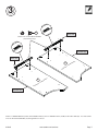
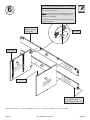
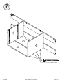
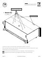
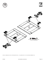
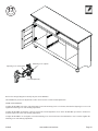
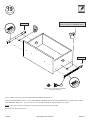
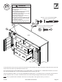
414942
Dresser
Harbor View Collection
PLEASE CONTACT US
BEFORE RETURNING
YOUR UNIT TO THE STORE
1-800-523-3987
www.sauder.com
NOTE: THIS INSTRUCTION BOOKLET CONTAINS
IMPORTANT SAFETY INFORMATION.
PLEASE READ AND KEEP FOR FUTURE REFERENCE.
English .................... Page 1-26
Français ...............Pages 27-29
Made in the USA
Archbold, OH
Espanol.............Páginas 30-32
Lot #: 353496
07 / 19 / 13
Date Purchased: ____________________
TABLE OF CONTENTS
ADULT ASSEMBLY REQUIRED
Part Identification ................... 2-3
Hardware Identification .............4
ASSEMBLY TOOLS REQUIRED
Assembly Steps .................... 5-26
No. 2 Phillips Screwdriver
Français .............................. 27-29
Tip Shown Actual Size
Espanol............................... 30-32
Safety ................................. 33-34
Hammer
Warranty ...................................35
PART IDENTIFICATION: While not all parts are labeled, some of the parts will have a label or an inked
letter on the edge to help distinguish similar parts from each other. Use this PART IDENTIFICATION to help
identify similar parts.
Page 2
A
RIGHT END
1
S
LEFT MOLDING
1
B
LEFT END
1
T
BOTTOM MOLDING
1
C
RIGHT UPRIGHT
1
U
SKIRT
1
D
LEFT UPRIGHT
1
V
BRACE MOLDING
1
E
UPRIGHT
1
W
DRAWER BRACE
4
F
TOP
1
X
BACK BRACE
1
G
BOTTOM
1
Y
FOOT
2
H
FRONT BRACE
1
D12
UPPER RIGHT DRAWER SIDE
1
I
BACK
1
D13
UPPER LEFT DRAWER SIDE
1
J
CENTER BACK
2
D24
RIGHT DRAWER SIDE
2
K
RIGHT DOOR
1
D25
LEFT DRAWER SIDE
2
L
LEFT DOOR
1
D30
LOWER RIGHT DRAWER SIDE
1
M
RIGHT DRAWER FRONT
1
D31
LOWER LEFT DRAWER SIDE
1
N
LEFT DRAWER FRONT
1
D166 UPPER DRAWER BACK
1
O
UPPER DRAWER FRONT
1
D167 LOWER DRAWER BACK
1
P
LOWER DRAWER FRONT
1
D170 DRAWER BACK
2
Q
FRONT MOLDING
1
D945 DRAWER BOTTOM
2
R
RIGHT MOLDING
1
D974 LOWER DRAWER BOTTOM
2
www.sauder.com/services
414942
PART IDENTIFICATION
R
F
Q
S
A
I
X
J
E
J
V
H
D
B
C
G
T
Y
K
U
D170
D24
L
D945
Y
D25
D170
D166
D24
M
W
D12
D945
D974
D25
D13
N
O
W
W
D30
D167
D974
P
D31
W
414942
www.sauder.com/services
Page 3
HARDWARE IDENTIFICATION
35GA
CABINET RIGHT - 4 35GB
10A SLIDE CAM - 8
1F HIDDEN CAM - 8
23F FOOT SCREW - 2
5L
DRAWER RIGHT - 4
2F CAM DOWEL - 8
1G SAFETY BRACKET - 1
WARNING LABEL - 1
!
CABINET LEFT - 4 35GC
10F
13H HINGE - 4
1M FELT DISC CARD - 1
1N
35GD
DRAWER LEFT - 4
TWIST-LOCK®
FASTENER - 18
5K KNOB - 6
NAIL - 49
MOLDING
CONNECTOR - 2
16F
98K PULL - 4
1R
METAL PIN - 4
WARNING
Serious or fatal crushing injuries can
occur from furniture tip-over. To help
prevent tip-over:
• Place heaviest items in the lowest drawers.
• Unless specifically designed to accommodate, do not
set TVs or other heavy objects on top of this product.
• Never allow children to climb or hang on drawers,
doors, or shelves.
• Never open more than one drawer at a time.
• If equipped with a drawer interlock system, do not
defeat or remove it.
Use of tip-over restraints may only reduce,
but not eliminate, the risk of tip-over.
This is a permanent label. Do not attempt to remove!
04/10
332296
(Refer to the last step for proper
location and application)
1S
BLACK 9/16" LARGE HEAD SCREW - 1
2S
BLACK 1-7/8" FLAT HEAD SCREW - 10
3S
GOLD 5/16" FLAT HEAD SCREW - 32
4S
BLACK 1-15/16" FLAT HEAD SCREW - 8
9S
BLACK 1-1/8" PAN HEAD SCREW - 6
11S BLACK 1/2" FLAT HEAD SCREW - 8
20S SILVER 3/4" MACHINE SCREW - 8
27S BLACK 1-5/8" PAN HEAD SCREW - 8
30S BLACK 1-9/16" FLAT HEAD SCREW - 20
42S SILVER 7/8" MACHINE SCREW - 6
Screws are shown actual size. You may receive extra hardware with your unit.
Page 4
www.sauder.com/services
414942
S
p
te
Look for this icon. It means a video
assembly tip is available at:
www.sauder.com/services/tips
1
Do not tighten the TWIST-LOCK® FASTENERS in this step.
10F
(18 used)
D
C
Assemble your unit on a carpeted floor or on the empty carton to avoid scratching your unit or the floor.
To begin assembly, push a SAUDER TWIST-LOCK® FASTENER (10F) into the large holes in the RIGHT UPRIGHT (C) and LEFT
UPRIGHT (D). Repeat this step for the UPRIGHT (E), BOTTOM (G), and BRACES (H and X).
414942
www.sauder.com/services
Page 5
S
p
te
2
Do not tighten the HIDDEN CAMS in this step.
W
W
W
B
W
A
Arrow
1F
Arrow
2F
Insert the metal end of the CAM
DOWEL into the HIDDEN CAM.
Push eight HIDDEN CAMS (1F) into the ENDS (A and B) and DRAWER BRACES (W). Then, insert the metal end of a CAM
DOWEL (2F) into each HIDDEN CAM.
Page 6
www.sauder.com/services
414942
S
p
te
3
3S
Roller end
GOLD 5/16” FLAT HEAD SCREW
(4 used in this step)
1
2
3
Finished edge
3
Roller end
le
s
2
h
ho
A
s
S
ur
fa
ce
w
it
1
S
ur
fa
ce
w
it
h
ho
le
B
Finished edge
Fasten a CABINET RIGHT (35GA) to the RIGHT END (A) and a CABINET LEFT (35GB) to the LEFT END (B). Use four GOLD
5/16" FLAT HEAD SCREWS (3S) through holes #1 and #3.
414942
www.sauder.com/services
Page 7
S
p
te
4
Roller end
3S
GOLD 5/16” FLAT HEAD SCREW
(12 used in this step)
1
2
3
1
2
C
3
3
2
1
®
ith CK
w
O S
aceST-L NER
f
r
SuTWI STE
FA
3
D
2
1
Roller end
Finished edge
®
ith CK
w
O
ce L RS
rfa IST- ENE
u
S TW ST
FA
Surface with
TWIST-LOCK®
FASTENERS
Finished edge
3
Roller end
2
1
E
Finished edge
3
2
1
Roller end
Fasten the CABINET RIGHTS (35GA) to the RIGHT UPRIGHT (C) and UPRIGHT (E) and the CABINET LEFTS (35GB) to
the LEFT UPRIGHT (D) and other surface of the UPRIGHT (E). Use twelve GOLD 5/16" FLAT HEAD SCREWS (3S) through
holes #1 and #3.
Page 8
www.sauder.com/services
414942
S
p
te
5
Use your hammer to tap the MOLDING CONNECTOR (16F) into the notches in the MOLDINGS.
Flat end
Flat end
16F
16F
S
Q
R
Tap two MOLDING CONNECTORS (16F) into the notches in the MOLDINGS (Q, R, and S).
414942
www.sauder.com/services
Page 9
S
p
te
How to use the SAUDER TWIST-LOCK® FASTENER
6
1. Insert the dowel end of the FASTENER into the
hole of the adjoining part.
NOTE: The dowel end of the FASTENER must remain
fully inserted in the hole of the adjoining part while
locking the FASTENER.
2. Tighten the FASTENER with a Phillips screwdriver
as tight as possible.
Edge with
TWIST-LOCK®
FASTENERS
Dowel end
Finished edge
H
D
ith ®
e wOCK
c
a
f
Sur IST-LERS
TWSTEN
FA
Su
TWrface
FA IST-with
ST LO
EN CK®
ER
S
X
C
Finished edge
t
hou®
t
i
ew K
fac -LOCS
r
u
S IST ER
TWSTEN
FA
Su
TWrface
FA IST-with
ST LO
EN CK®
ER
S
The long edge closer
to the TWIST-LOCK®
FASTENERS should be here.
Fasten the UPRIGHTS (C and D) to the BRACES (H and X). Tighten four TWIST-LOCK® FASTENERS.
Page 10
www.sauder.com/services
414942
S
p
te
7
D
J
J
C
4S
BLACK 1-15/16" FLAT HEAD SCREW
(8 used in this step)
Fasten the BACKS (J) to the UPRIGHTS (C and D). Use eight BLACK 1-15/16" FLAT HEAD SCREWS (4S).
414942
www.sauder.com/services
Page 11
S
p
te
8
1R
Finished edge
B
h
wit MS
e
c
fa CA
Sur DEN
HID
H
D
X
G
Su
r
f
a
TW ce
FA IST-with
ST LO
EN CK®
ER
S
C
2S
BLACK 1-7/8" FLAT HEAD SCREW
(4 used in this step)
This hole
must be here.
Insert two METAL PINS (1R) into the BRACES (H and X).
Fasten the LEFT END (B) to the BRACES (H and X). Tighten two TWIST-LOCK® FASTENERS.
NOTE: Be sure the METAL PINS in the BRACES (H and X) insert into the holes in the LEFT END (B).
Fasten the BOTTOM (G) to the LEFT END (B). Tighten two TWIST-LOCK® FASTENERS.
Then, fasten the BOTTOM (G) to the UPRIGHTS (C and D). Use four BLACK 1-7/8" FLAT HEAD SCREWS (2S).
Page 12
www.sauder.com/services
414942
S
p
te
9
H
Finished edge
G
X
A
t
hou S
t
i
w
ace CAM
f
r
Su DEN
HID
1R
Insert two METAL PINS (1R) into the BRACES (H and X).
Fasten the RIGHT END (A) to the BOTTOM (G) and BRACES (H and X). Tighten four TWIST-LOCK® FASTENERS.
NOTE: Be sure the METAL PINS in the BRACES (H and X) insert into the holes in the RIGHT END (A).
414942
www.sauder.com/services
Page 13
S
p
te
10
V
Surface with
TWIST-LOCK®
FASTENERS
Finished edge
E
H
X
2S
BLACK 1-7/8" FLAT HEAD SCREW
(2 used in this step)
Fasten the BRACE MOLDING (V) to the FRONT BRACE (H). Tighten four TWIST-LOCK® FASTENERS.
Fasten the UPRIGHT (E) to the BRACES (H and X). Use two BLACK 1-7/8" FLAT HEAD SCREWS (2S).
Page 14
www.sauder.com/services
414942
S
p
te
11
27S
BLACK 1-5/8" PAN HEAD SCREW
(8 used in this step)
R
Q
S
F
ce
fa
ur
S
Rounded edge
w
h
it
s
le
ho
Fasten the MOLDINGS (Q, R, and S) to the TOP (F). Use eight BLACK 1-5/8" PAN HEAD SCREWS (27S).
414942
www.sauder.com/services
Page 15
S
p
te
12
Rounded edge
S
B
E
F
Su
r
f
ho ace
les w
it
h
R
A
Fasten the ENDS (A and B) to the MOLDINGS (R and S) on the TOP (F). Tighten four HIDDEN CAMS.
NOTE: Be sure the dowel ends of the TWIST-LOCK® FASTENERS in the UPRIGHT (E) insert into the holes in the TOP (F).
Then, fasten the TOP (F) to the UPRIGHT (E). Tighten two TWIST-LOCK® FASTENERS.
Caution
Risk of damage or
injury. Hidden Cams
must be completely
tightened. Hidden
Cams that are not
completely tightened
may loosen, and parts
may separate.
To completely tighten:
Page 16
Start
Arrow
Tighten
Maximum
210 degrees
Arrow
Minimum
190 degrees
www.sauder.com/services
414942
S
p
te
13
9S
BLACK 1-1/8" PAN HEAD SCREW
(6 used for the BOTTOM MOLDING)
Rounded edge
Y
T
Y
23F
Rounded edge
2S
BLACK 1-7/8" FLAT HEAD SCREW
(3 used for the SKIRT)
Flat surface
U
T
Unfinished
surface
First, fasten the SKIRT (U) to the BOTTOM MOLDING (T). Use three BLACK 1-7/8" FLAT HEAD SCREWS (2S).
Then, fasten the BOTTOM MOLDING (T) to the BOTTOM (G). Use six BLACK 1-1/8" PAN HEAD SCREWS (9S).
Carefully turn two FOOT SCREWS (23F) a few turns into the BOTTOM MOLDING (T).
Next, turn a FOOT (Y) onto the other end of each FOOT SCREW (23F). Turn the FEET clockwise until the FOOT SCREW is tight in
the BOTTOM MOLDING (T) and each FOOT.
NOTE: Do not overtighten the FOOT SCREWS.
414942
www.sauder.com/services
Page 17
S
p
te
Caution
Do not stand the unit upright without the
BACK fastened. The unit may collapse.
14
These holes must line up over the
UPRIGHTS and BACK BRACE.
1N
NAIL
(49 used in this step)
Cut-out (used for lifting)
I
Carefully turn your unit over onto its front edges. Unfold the BACK (I) and lay it over your unit.
Make equal margins along all four edges of the BACK (I). Push on opposite corners of your unit if needed to make it “square”.
Fasten the BACK (I) to your unit using the NAILS (1N).
NOTE: Be sure to tap NAILS into the holes that line up over the UPRIGHTS (C and D) and BACK BRACE (X).
NOTE: Perforations have been provided for access through the BACK. Carefully cut out the holes needed.
Page 18
www.sauder.com/services
414942
S
p
te
15
13H
L
K
11S
BLACK 1/2” FLAT HEAD SCREW
(8 used for the HINGES)
13H
Fasten two HINGES (13H) to each DOOR (K and L). Use eight BLACK 1/2" FLAT HEAD SCREWS (11S).
414942
www.sauder.com/services
Page 19
S
p
te
16
Adjusting screw (horizontal)
Mounting screw (depth)
1M
B
5K
L
D
1M
42S
SILVER 7/8" MACHINE SCREW
(2 used for the KNOBS)
Carefully stand your unit upright.
NOTE: You may need to loosen the mounting and adjusting screws to slide the hinge part way out of the slot before fastening it to the
END. Retighten the screw before you mount the HINGE to the END.
Fasten the LEFT DOOR (L) to the LEFT END (B). Use the screws in the HINGES. See the next step for adjustments.
Fasten a KNOB (5K) to the LEFT DOOR (L). Use a SILVER 7/8" MACHINE SCREW (42S).
Peel a FELT DISC from the FELT DISC CARD (1M) and stick it on the DOOR where it comes in contact with the LEFT UPRIGHT (D).
Repeat this step for the other door.
Page 20
www.sauder.com/services
414942
S
p
te
17
Adjusting screw (horizontal)
Mounting screw (depth)
(vertical adjustment)
Refer to the enlarged diagram to identify the parts on the HINGES.
The DOORS may need some adjustments. Follow the text below to make needed adjustments.
DOOR ADJUSTMENTS:
To adjust the DOORS from side to side (horizontal), loosen the mounting screw several turns, then turn the adjusting screw in or out.
Tighten the mounting screw after making adjustments.
To adjust the DOORS up and down (vertical), loosen both vertical adjustment screws. Move the DOORS up or down to the desired
location. Tighten the screws after making adjustments.
To adjust the DOORS in or out (depth), loosen the mounting screw one turn and move the DOORS in or out, as needed. Tighten the
mounting screw after making adjustments.
414942
www.sauder.com/services
Page 21
S
VIEW THE T-LOCK BOX VIDEO
p
te
18
1
The tabs should insert freely into the slots.
Gently tilt the DRAWER SIDES side to
side until the tabs slip into the slots.
2
With the palm of your hand, tap the
DRAWER BOTTOM down into the groove.
D974
UN
FI
NI
D30
ED
D30
P
SH
D31
P
Groove
D31
Be sure the DRAWER
BOTTOM inserts into the
DRAWER FRONT groove.
Insert the LOWER DRAWER SIDES (D30 and D31) at an angle
into the slot at each end of the LOWER DRAWER FRONT (P).
3
Maximum
210 degrees
Arrow
Slide the LOWER DRAWER BOTTOM (D974) into the grooves
in the LOWER DRAWER SIDES (D30 and D31) and LOWER
DRAWER FRONT (P).
Start each screw a few turns before
completely tightening any of them.
4
30S
Minimum
190 degrees
BLACK 1-9/16" FLAT HEAD SCREW
(20 used in this step)
D167
W
D30
W
D31
Surface with
HIDDEN CAM
P
Fasten the DRAWER BRACE (W) to the LOWER DRAWER
FRONT (P). Tighten one HIDDEN CAM.
Page 22
Fasten the LOWER DRAWER BACK (D167) to the LOWER
DRAWER SIDES (D30 and D31) and DRAWER BRACE (W).
Use five BLACK 1-9/16" FLAT HEAD SCREWS (30S).
Repeat this step for the other drawers. The drawers will use DRAWER
FRONTS (M and N), DRAWER SIDES (D24 and D25), DRAWER
BACKS (D170), and DRAWER BOTTOM (D945). The upper
drawer will use UPPER DRAWER FRONT (O), UPPER DRAWER
SIDES (D12 and D13), UPPER DRAWER BACK (D166), and the
remaining LOWER DRAWER BOTTOM (D974).
www.sauder.com/services
414942
S
p
te
19
Screw head - turn CAM to line up holes in
SLIDES with holes in DRAWER SIDES.
Roller end
10A
1
10A
3
2
D31
Roller end
D30
1
3
2
3S
GOLD 5/16” FLAT HEAD SCREW
(16 used in this step)
Insert a SLIDE CAM (10A) into the LOWER DRAWER SIDES (D30 and D31).
Fasten a DRAWER RIGHT (35GC) to the LOWER RIGHT DRAWER SIDE (D30) and a DRAWER LEFT (35GD) to the LOWER
LEFT DRAWER SIDE (D31). Use four GOLD 5/16" FLAT HEAD SCREWS (3S) through holes #1 and #3.
NOTE: The screw head in the CAM must be visible through the slotted hole in the SLIDE.
Repeat this step for the other drawers.
414942
www.sauder.com/services
Page 23
S
p
te
42S
20
SILVER 7/8" MACHINE SCREW
(4 used for the KNOBS)
N
5K
20S
SILVER 3/4" MACHINE SCREW
(8 used for the PULLS)
P
98K
Fasten two KNOBS (5K) to the LEFT DRAWER FRONT (N). Use two SILVER 7/8" MACHINE SCREWS (42S). Repeat this step
for the RIGHT DRAWER FRONT (M).
Fasten two PULLS (98K) to the LOWER DRAWER FRONT (P). Use four SILVER 3/4" MACHINE SCREWS (20S). Repeat this
step for the UPPER DRAWER FRONT (O).
Page 24
www.sauder.com/services
414942
S
p
te
21
WARNING
Serious or fatal crushing injuries can
occur from furniture tip-over. To help
prevent tip-over:
-Place heaviest items in the lowest drawers.
-Unless specifically designed to
accommodate, do not set TVs or other heavy
objects on top of this product.
-Never allow children to climb or hang on
drawers, doors, or shelves.
-Never open more than one drawer at a time.
-If equipped with a drawer interlock system,
do not defeat or remove it.
Use of tip-over restraints may only reduce,
but not eliminate, the risk of tip-over.
BLACK 1-7/8" FLAT HEAD SCREW
(1 used into a stud in your wall)
2S
1G
D945
BLACK 9/16" LARGE HEAD SCREW
(1 used into the top of your unit)
5L
1S
50 lbs.
20 lbs.
N
20 lbs.
M
30 lbs.
O
30 lbs.
30 lbs.
P
30 lbs.
To insert the drawers into your unit, tip the front of the drawers down and drop the rollers on the drawers behind the rollers on the unit.
Lift the front of the drawers up and slide them into the unit.
We recommend using the SAFETY BRACKET (1G) for added stability. Use a BLACK 9/16" LARGE HEAD SCREW (1S) into the
top of the unit and a BLACK 1-7/8" FLAT HEAD SCREW (2S) into a stud in your wall.
Apply the WARNING LABEL (5L) to the upper DRAWER BOTTOM (D945). You should be able to read the label when the drawer
is open. When the drawer is closed, it will hide the label. Peel off the backing and apply the label as shown in the diagram.
NOTE: This is a permanent label intended to last for the life of the product. Once applied, do not try to remove it.
414942
www.sauder.com/services
Page 25
S
p
te
22
Loosen screw #3 a 1/4 turn, turn the cam a 1/4 turn
maximum in both the clockwise and counter-clockwise
directions to make adjustments, and then tighten screw #3.
The higher the screw in the oblong hole, the
higher your drawer front will be. The lower
the screw, the lower the drawer front.
Cam
To make adjustments to the drawers, loosen SCREW #3 in the SLIDES a 1/4 turn, then turn the CAM clockwise or counter-clockwise.
Notice how the drawer raises or lowers as you turn the CAM. The higher the screw in the oblong hole, the higher your drawer front
will be. The lower the screw, the lower the drawer front. By adjusting the drawers this way, it will help the DRAWER FRONTS line
up better when closed. Tighten the SCREW when finished with adjustments.
NOTE: Please read the back pages of the instruction booklet for important safety information.
This completes assembly. To clean your unit, dampen a cloth with tap water and wipe.
Page 26
www.sauder.com/services
414942
414942
Utilisez les instructions d’assemblage en français avec
les schémas étape par étape du manuel d’instruction
en anglais. Chaque étape en français correspond à la
même étape en anglais. La pièce devant être attachée
à l’élément est représentée en gris sur les schémas de
chaque étape pour plus de précision. Comparer la “Liste
de pièces” ci-dessous avec la “PART IDENTIFICATION”
du manuel en anglais pour vous familiariser avec les
pièces avant l’assemblage.
REMARQUE : CE MANUEL D’INSTRUCTIONS
CONTIENT D’IMPORTANTES INFORMATIONS
RELATIVES À LA SÉCURITÉ. À LIRE ET CONSERVER
POUR TOUTE RÉFÉRENCE FUTURE.
Commode
NOUS SOMMES LA POUR VOUS AIDER!
Nous faisons de notre mieux pour nous assurer que
votre meuble arrive dans d’excellentes conditions. Nos
représentants du service Clientèle sont aimables et prêts
à vous aider au cas où une pièce aurait été endommagée
ou manquerait (ou si vous aviez besoin d’aide pour
l’assemblage). NE RAMENEZ PAS LE MEUBLE AU
MAGASIN. Au Canada, composez ce numéro d’appel gratuit:
1-800-523-3987
Du lundi au vendredi, de 9 heures du matin à
5:30 heures du soir (horaire Côte Est)
(sauf jours fériés)
Si une pièce a besoin d’être remplacée, la pièce de
remplacement sera envoyée dans les 48 heures. (Sauf
week-ends et jours fériés)
LISTE DE PIÈCES
REFERENCE DESCRIPTION
A l’usage exclusif du
Canada Noter la date
d’achat de cet élément
et conserver le livret
pour future référence.
Pour contacter Sauder
en ce qui concerne cet
élément, faire référence
au numéro de lot et
numéro de modèle en
appelant notre numéro
sans frais.
Lot nº : ____________
Date de
l’achat: ____________
414942
QUANTITÉ
A
EXTRÉMITÉ DROITE ............................ 1
B
EXTRÉMITÉ GAUCHE .......................... 1
C
MONTANT DROIT ................................. 1
D
MONTANT GAUCHE ............................. 1
E
MONTANT ............................................. 1
F
DESSUS ................................................ 1
G
DESSOUS ............................................. 1
H
ENTRETOISE FRONTALE .................... 1
I
ARRIÈRE ............................................... 1
J
ARRIÈRE CENTRAL ............................. 2
K
PORTE DROITE .................................... 1
L
PORTE GAUCHE .................................. 1
M
DEVANT DE TIROIR DROIT ................. 1
N
DEVANT DE TIROIR GAUCHE ............. 1
O
DEVANT DE TIROIR SUPÉRIEUR........ 1
P
DEVANT DE TIROIR INFÉRIEUR ......... 1
Q
MOULURE AVANT ................................. 1
R
MOULURE DROITE .............................. 1
S
MOULURE GAUCHE............................. 1
T
MOULURE DE DESSOUS .................... 1
U
PLINTHE ................................................ 1
V
MOULURE D'ENTRETOISE .................. 1
W
ENTRETOISE DE TIROIR ..................... 4
X
ENTRETOISE ARRIÈRE ....................... 1
Y
PIED....................................................... 2
D12 CÔTÉ DROIT DE TIROIR SUPÉRIEUR 1
D13 CÔTÉ GAUCHE DE TIROIR SUPÉRIEUR 1
D24 CÔTÉ DROIT DE TIROIR ...................... 2
D25 CÔTÉ GAUCHE DE TIROIR ................. 2
D30 CÔTÉ DROIT DE TIROIR INFÉRIEUR . 1
D31 CÔTÉ GAUCHE DE TIROIR INFÉRIEUR 1
D166 ARRIÈRE DE TIROIR SUPÉRIEUR ...... 1
D167 ARRIÈRE DE TIROIR INFÉRIEUR ....... 1
D170 ARRIÈRE DE TIROIR ............................ 2
D945 FOND DE TIROIR.................................. 2
D974 FOND DE TIROIR INFÉRIEUR ............. 2
www.sauder.com/services
LISTE DE PIÈCES
REFERENCE DESCRIPTION
QUANTITÉ
35GA ÉLÉMENT DROITE ............................... 4
35GB ÉLÉMENT GAUCHE.............................. 4
35GC TIROIR DROIT....................................... 4
35GD TIROIR GAUCHE .................................. 4
10A EXCENTRIQUE DE COULISSE ............ 8
1F EXCENTRIQUE ESCAMOTABLE ......... 8
2F CHEVILLE D'EXCENTRIQUE ............... 8
10F FIXATION TWIST-LOCK® ................... 18
16F CONNECTEUR DE MOULURE............. 2
23F VIS DE PIED .......................................... 2
1G CONSOLE DE SÉCURITÉ .................... 1
13H CHARNIÈRE .......................................... 4
5K BOUTON................................................ 6
98K POIGNÉE............................................... 4
5L
ÉTIQUETTE DE MISE EN GARDE ....... 1
(Consulter la dernière étape pour l'emplacement
et application appropriées)
1M FICHE DE TAMPONS EN FEUTRE ...... 1
1N CLOU ................................................... 49
1R GOUPILLE EN MÉTAL .......................... 4
1S VIS TÊTE LARGE 14 mm NOIRE ......... 1
2S VIS TÊTE PLATE 48 mm NOIRE ........ 10
3S VIS TÊTE PLATE 8 mm DORÉE ......... 32
4S VIS TÊTE PLATE 49 mm NOIRE .......... 8
9S VIS TÊTE GOUTTE DE SUIF 28 mm
NOIRE.................................................... 6
11S VIS TÊTE PLATE 13 mm NOIRE .......... 8
20S VIS À MÉTAUX 19 mm ARGENT .......... 8
27S VIS TÊTE GOUTTE DE SUIF 41 mm
NOIRE.................................................... 8
30S VIS TÊTE PLATE 40 mm NOIRE ........ 20
42S VIS À MÉTAUX 22 mm ARGENT .......... 6
Page 27
ÉTAPE 1
ÉTAPE 9
Ne pas serrer les FIXATIONS TWIST-LOCK® à cette étape.
Assembler l'élément sur un sol à moquette ou sur le carton
vide pour éviter d'endommager l'élément ou le sol.
Pour commencer l'assemblage, enfoncer une FIXATION TWISTLOCK® SAUDER (10F) dans les gros trous du MONTANT DROIT (C)
et du MONTANT GAUCHE (D). Répéter cette étape pour le
MONTANT (E), le DESSOUS (G) et les ENTRETOISES (H et X).
Insérer deux GOUPILLES EN MÉTAL (1R) dans les ENTRETOISES (H et X).
Fixer l'EXTRÉMITÉ DROITE (A) au DESSOUS (G) et aux
ENTRETOISES (H et X). Serrer quatre FIXATIONS TWIST-LOCK®.
REMARQUE : S'assurer de bien insérer les GOUPILLES EN
MÉTAL situées sur les ENTRETOISES (H et X) dans les trous
sur l'EXTRÉMITÉ DROITE (A).
ÉTAPE 10
ÉTAPE 2
Ne pas serrer les EXCENTRIQUES ESCAMOTABLES dans
cette étape.
Enfoncer huit EXCENTRIQUES ESCAMOTABLES (1F) dans les
EXTRÉMITÉS (A et B) et les ENTRETOISES DE
TIROIR (W). Ensuite, insérer l'extrémité en métal de la CHEVILLE
D'EXCENTRIQUE (2F) dans chaque EXCENTRIQUE ESCAMOTABLE.
Fixer la MOULURE D'ENTRETOISE (V) à l'ENTRETOISE
AVANT (H). Serrer quatre FIXATIONS TWIST-LOCK®.
Fixer le MONTANT (E) aux ENTRETOISES (H et X). Utiliser
deux VIS TÊTE PLATE 48 mm NOIRES (2S).
ÉTAPE 11
Fixer les MOULURES (Q, R et S) au DESSUS (F). Utiliser huit
VIS TÊTE GOUTTE DE SUIF 41 mm NOIRES (27S).
ÉTAPE 3
Fixer une ÉLÉMENT DROITE (35GA) à l’EXTRÉMITÉ DROITE (A)
et une ÉLÉMENT GAUCHE (35GB) à l’EXTRÉMITÉ GAUCHE (B).
Utiliser quatre VIS TÊTE PLATE 8 mm DORÉES (3S) à travers les
trous nº 1 et nº 3.
ÉTAPE 4
Fixer les ÉLÉMENTS DROITES (35GA) au MONTANT DROIT (C)
et au MONTANT (E) et les ÉLÉMENTS GAUCHES (35GB) au
MONTANT GAUCHE (D) et sur l'autre surface du MONTANT (E).
Utiliser douze VIS TÊTE PLATE 8 mm DORÉES (3S) à travers
les trous nº 1 et nº 3.
ÉTAPE 5
Enfoncer deux CONNECTEURS DE MOULURE (16F) dans
les crans des MOULURES (Q, R et S).
ÉTAPE 12
Fixer les EXTRÉMITÉS (A et B) aux MOULURES (R et S) et au
DESSUS (F). Serrer quatre EXCENTRIQUES ESCAMOTABLES.
REMARQUE : S’assurer que l’extrémité à cheville des
FIXATIONS TWIST-LOCK® du MONTANT (E) sont insérées
dans les trous du DESSUS (F). Ensuite fixer le DESSUS (F) au
MONTANT (E). Serrer deux FIXATIONS TWIST-LOCK®.
Attention: Risque des dégâts ou blessures. Les Excentriques
Escamotables doivent être serrés à bloc. Les Excentriques
Escamotables que ne sont pas serrées à bloc peuvent
desserrer et les pièces peuvent séparer. Pour serrer à bloc,
faire tourner l'excentrique escamotable de 210 degrés.
ÉTAPE 13
Utilisation de la FIXATION TWIST-LOCK® SAUDER
1. Insérer l'extrémité filetée de la FIXATION dans le trou de la
pièce attenante.
REMARQUE : L'extrémité filetée de la FIXATION doit rester
complètement insérée dans le trou de la pièce attenante
lorsque l'on bloque la FIXATION.
2. Bien serrer la FIXATION à l'aide d'un tournevis Phillips.
Fixer les MONTANTS (C et D) aux ENTRETOISES (H et X).
Serrer quatre FIXATIONS TWIST-LOCK®.
Tout d'abord, fixer la PLINTHE (U) à la MOULURE DE DESSOUS (T).
Utiliser trois VIS TÊTE PLATE 48 mm NOIRES (2S).
Ensuite, fixer la MOULURE DE DESSOUS (T) au DESSOUS (G).
Utiliser six VIS TÊTE GOUTTE DE SUIF 28 mm NOIRES (9S).
Faire soigneusement tourner deux VIS DE PIED (23F) de
quelques tours dans la MOULURE DE DESSOUS (T).
Ensuite, faire tourner un PIED (Y) sur l’autre extrémité de chaque
VIS DE PIED (23F). Faire tourner les PIEDS dans le sens des
aiguilles d’une montre jusqu’à ce que la VIS DE PIED soit serrée
dans la MOULURE DE DESSOUS (T) et chaque PIED.
REMARQUE : Ne pas trop serrer les VIS DE PIED.
ÉTAPE 7
ÉTAPE 14
Fixer les ARRIÈRES (J) aux MONTANTS (C et D). Utiliser huit
VIS TÊTE PLATE 49 mm NOIRES (4S).
Attention: Ne pas relever l'élément dans sa position verticale
avant d'avoir fixé l’ARRIÈRE. L'élément risque de s'effondrer.
Avec précaution, retourner l'élément sur ses chants avant.
Déplier l'ARRIÈRE (I) et le placer sur l'élément.
Veiller à avoir des marges égales le long des quatre chants de
l'ARRIÈRE (I). Si besoin est, enfoncer sur les coins opposés
de l'élément pour s'assurer d'être « d'équerre ».
Fixer l'ARRIÈRE (I) à l'élément à l'aide des CLOUS (1N).
REMARQUE : S'assurer de bien enfoncer les CLOUS dans
les trous qui sont alignés sur les MONTANTS (C et D) et
l'ENTRETOISE ARRIÈRE (X).
REMARQUE : Des lignes perforées ont été prévues pour
accéder facilement à l'ARRIÈRE. Découper avec précaution
les trous nécessaires.
ÉTAPE 6
ÉTAPE 8
Insérer deux GOUPILLES EN MÉTAL (1R) dans les ENTRETOISES (H et X).
Fixer l'EXTRÉMITÉ GAUCHE (B) aux ENTRETOISES (H et X).
Serrer deux FIXATIONS TWIST-LOCK®.
REMARQUE : S'assurer de bien insérer les GOUPILLES EN
MÉTAL situées sur les ENTRETOISES (H et X) dans les trous
sur l'EXTRÉMITÉ GAUCHE (B).
Fixer le DESSOUS (G) à l'EXTRÉMITÉ GAUCHE (B). Serrer
deux FIXATIONS TWIST-LOCK®.
Ensuite, fixer le DESSOUS (G) aux MONTANTS (C et D).
Utiliser quatre VIS TÊTE PLATE 48 mm NOIRES (2S).
Page 28
www.sauder.com/services
414942
ÉTAPE 15
ÉTAPE 19
Fixer deux CHARNIÈRES (13H) à chaque PORTE (K et L).
Utiliser huit VIS TÊTE PLATE 13 mm NOIRES (11S).
Insérer une EXCENTRIQUE DE COULISSE (10A) dans les
CÔTÉS DE TIROIR INFÉRIEUR (D30 et D31).
Fixer un TIROIR DROIT (35GC) sur le CÔTÉ DROIT DE
TIROIR INFÉRIEUR (D30) et un TIROIR GAUCHE (35GD)
sur le CÔTÉ GAUCHE DE TIROIR INFÉRIEUR (D31). Utiliser
quatre VIS TÊTE PLATE 8 mm DORÉES (3S) à travers les
trous nº 1 et nº 3.
REMARQUE : La tête de vis dans l'EXCENTRIQUE doit être
visible à travers le trou fendu dans la COULISSE.
Répéter cette étape pour les autres tiroirs.
ÉTAPE 16
Relever, avec précaution, l'élément dans sa position verticale.
REMARQUE : Il est peut-être nécessaire de desserrer les
vis de montage et de réglage pour faire glisser la charnière
partiellement hors de la fente avant de la fixer à l’EXTRÉMITÉ.
Resserrer la vis avant de monter la CHARNIÈRE à
l’EXTRÉMITÉ.
Fixer la PORTE GAUCHE (L) à l'EXTRÉMITÉ GAUCHE (B).
Utiliser les vis fournies avec les CHARNIÈRES. Voir l'étape
suivante pour réglages.
Fixer un BOUTON (5K) à la PORTE GAUCHE (L). Utiliser une
VIS À MÉTAUX 22 mm ARGENT (42S).
Séparer un TAMPON EN FEUTRE de la FICHE AVEC TAMPONS
EN FEUTRE (1M) et le coller sur la PORTE aux endroits où celleci entre en contact avec le MONTANT GAUCHE (D).
Répéter cette étape pour l'autre porte.
ÉTAPE 20
Fixer deux BOUTONS (5K) au DEVANT DE TIROIR GAUCHE (N).
Utiliser deux VIS À MÉTAUX 22 mm ARGENTÉES (42S). Répéter
cette étape pour le DEVANT DE TIROIR DROIT (M).
Fixer deux POIGNÉES (98K) au DEVANT DE TIROIR
INFÉRIEUR (P). Utiliser quatre VIS À MÉTAUX 19 mm
ARGENTÉES (20S). Répéter cette étape pour le DEVANT DE
TIROIR SUPÉRIEUR (O).
ÉTAPE 17
ÉTAPE 21
Consulter le schéma agrandi pour identifier les pièces des
CHARNIÈRES.
Il faut peut-être ajuster les PORTES. Suivre les indications cidessous pour ajuster.
RÉGLAGES DES PORTES :
Pour ajuster les PORTES latéralement (horizontalement),
desserrer la vis de montage quelques tours et tourner la vis
de réglage vers l'intérieur ou vers l'extérieur. Serrer la vis de
montage après avoir ajusté.
Pour ajuster les PORTES de haut en bas (verticalement),
desserrer les deux vis de réglage. Déplacer les PORTES
verticalement à l'emplacement désiré. Serrer les vis après
avoir ajusté.
Pour ajuster les PORTES vers l'intérieur où vers l'extérieur
(profondeur), desserrer la vis de montage un tour et déplacer
les PORTES vers l'intérieur ou vers l'extérieur. Serrer la vis de
montage après avoir ajusté.
Pour insérer les tiroirs dans l'élément, abaisser le devant des
tiroirs et faire passer les roulettes situées sur les tiroirs derrière
les roulettes situées sur l'élément. Relever les devants du tiroir
et les enfiler dans l'élément.
Il est recommandé d'utiliser la CONSOLE DE SÉCURITÉ (1G)
pour renforcer la stabilité. Utiliser une VIS TÊTE LARGE
14 mm NOIRE (1S) dans le haut de l'élément et une VIS
TÊTE PLATE 48 mm NOIRE (2S) dans un montant du mur.
Apposer l'ÉTIQUETTE DE MISE EN GARDE (5L) sur le FOND
DU TIROIR supérieur (D945). Cette étiquette doit être lisible
lorsque le tiroir est ouvert. Lorsque le tiroir est fermé, il doit
la dissimuler. Décoller le film protecteur et apposer l'étiquette
comme l'indique le schéma.
REMARQUE : Cette étiquette permanente est prévue pour
durer pendant toute la vie du produit. Une fois apposée, ne pas
essayer de la retirer.
ÉTAPE 18
Pour ajuster les tiroirs, desserrer la VIS nº 3 dans les COULISSES
un quart de tour et tourner ensuite la CAME dans le sens des
aiguilles d'une montre ou dans le sens contraire. Noter que le tiroir
monte ou descend lorsque l'on tourne la CAME. Plus la vis dans
le trou oblong est haute, plus le devant de tiroir sera haut. Plus la
vis est basse, plus le devant de tiroir sera bas. Ajuster les tiroirs
de cette manière permet aux DEVANTS DE TIROIR d'être mieux
alignés une fois fermés. Resserrer la VIS après d'avoir ajusté.
REMARQUE : Prière de lire les informations importantes
sur la sécurité figurant sur les pages arrière du manuel
d’instructions.
Ceci complète l'assemblage. Pour nettoyer l’unité, humidifier
un chiffon avec de l’eau du robinet et essuyer.
1
Insérer les CÔTÉS DE TIROIR INFÉRIEUR (D30
et D31) en biseau dans la fente dans chaque extrémité du
DEVANT DE TIROIR INFÉRIEUR (P).
2
Enfiler le FOND DE TIROIR INFÉRIEUR (D974) dans
les rainures des CÔTÉS DE TIROIR INFÉRIEUR (D30 et D31)
et du DEVANT DE TIROIR INFÉRIEUR (P).
3
Fixer l’ENTRETOISE DE TIROIR (W) au DEVANT
DE TIROIR INFÉRIEUR (P). Serrer un EXCENTRIQUE
ESCAMOTABLE.
4
Fixer l'ARRIÈRE DE TIROIR INFÉRIEUR (D167)
aux CÔTÉS DE TIROIR INFÉRIEUR (D30 et D31) et à
l’ENTRETOISE DE TIROIR (W).
Utiliser cinq VIS TÊTE PLATE 40 mm NOIRES (30S).
Répéter cette étape pour les autres tiroirs. Les tiroirs utiliseront les
DEVANTS DE TIROIR (M et N), les CÔTÉS DE TIROIR (D24 et D25),
les ARRIÈRES DE TIROIR (D170) et FOND DE TIROIR (D945). Le
tiroir supérieur utilisera le DEVANT DE TIROIR SUPÉRIEUR (O),
les CÔTÉS DE TIROIR SUPÉRIEUR (D12 et D13), l'ARRIÈRE DE
TIROIR SUPÉRIEUR (D166) et l'autre FOND DE TIROIR
INFÉRIEUR (D974).
414942
ÉTAPE 22
www.sauder.com/services
Page 29
414942
Use estas instrucciones de ensamblaje en español junto
con las figuras paso-a-paso provistas en el folleto inglés.
Cada paso en español corresponde al mismo paso en
inglés. Se destacan las figuras de cada paso con una
tonalidad oscura para mostrar precisamente cual parte se
debe montar a la unidad. Compare la “Lista de Part” abajo
con la “Part Identification” en el folleto en inglés para
familiarizarse con Las partes de ensamblaje.
NOTA: ESTE FOLLETO DE INSTRUCCIONES
CONTIENE INFORMACIÓN IMPORTANTE SOBRE LA
SEGURIDAD. POR FAVOR LEA Y GUÁRDELO PARA
REFERENCIA EN EL FUTURO.
Cómoda
ESTAMOS AQUI PARA AYUDAR!
Tratamos de asegurar que su mueble llega en condición
excelente. Nuestros representantes de Servicio al Cliente
son amables y listos para ayudarle con servicio rápido
y eficiente si una parte está defectuosa o ausente (o si
necesita ayuda con el ensamblaje). NO DEVUELVA LA
UNIDAD A LA TIENDA. Llame este número sin cargo:
1-800-523-3987
Lunes a viernes, 9:00 a.m. - 5:30 p.m.
Hora oficial del Este
(excepto días festivos)
Si requiere un repuesto de una parte, será enviado dentro
de 48 horas (excepto los fines de semana y días festivos)
LISTA DE PARTES
ITEM
Anote la fecha de
comprar esta unidad y
guarde el folleto para
su referencia futura.
Si necesita ponerse
en contacto con
Sauder en cuanto a
esta unidad, refiérase
al número de lote y
al número de modelo
cuando llame a nuestro
número gratis.
No. Lote: ___________
Fecha
de compra: _________
Page 30
DESCRIPCIÓN
CANTIDAD
A
EXTREMO DERECHO .......................... 1
B
EXTREMO IZQUIERDO ........................ 1
C
PARAL DERECHO................................. 1
D
PARAL IZQUIERDO............................... 1
E
PARAL.................................................... 1
F
PANEL SUPERIOR ................................ 1
G
FONDO .................................................. 1
H
RIOSTRA FRONTALE ........................... 1
I
DORSO .................................................. 1
J
DORSO CENTRAL ................................ 2
K
PUERTA DERECHA .............................. 1
L
PUERTA IZQUIERDA ............................ 1
M
CARA DERECHA DE CAJÓN................ 1
N
CARA IZQUIERDA DE CAJÓN.............. 1
O
CARA DE CAJÓN SUPERIOR .............. 1
P
CARA DE CAJÓN INFERIOR ................ 1
Q
MOLDURA DELANTERA....................... 1
R
MOLDURA DERECHA........................... 1
S
MOLDURA IZQUIERDA......................... 1
T
MOLDURA DE FONDO ......................... 1
U
FALDÓN................................................. 1
V
MOLDURA DE RIOSTRA ...................... 1
W
RIOSTRA DE CAJÓN ............................ 4
X
RIOSTRA POSTERIOR ......................... 1
Y
PIE ......................................................... 2
D12 LADO DERECHO DE CAJÓN SUPERIOR 1
D13 LADO IZQUIERDO DE CAJÓN SUPERIOR 1
D24 LADO DERECHO DE CAJÓN ............... 2
D25 LADO IZQUIERDO DE CAJÓN ............. 2
D30 LADO DERECHO DE CAJÓN INFERIOR 1
D31 LADO IZQUIERDO DE CAJÓN INFERIOR 1
D166 DORSO DE CAJÓN SUPERIOR ........... 1
D167 DORSO DE CAJÓN INFERIOR ............ 1
D170 DORSO DE CAJÓN............................... 2
D945 FONDO DE CAJÓN ............................... 2
D974 FONDO DE CAJÓN INFERIOR............. 2
www.sauder.com/services
LISTA DE PARTES
ITEM
DESCRIPCIÓN
CANTIDAD
35GA GABINETE DERECHO .......................... 4
35GB GABINETE IZQUIERDO ........................ 4
35GC CAJÓN DERECHO ................................ 4
35GD CAJÓN IZQUIERDO .............................. 4
10A EXCÉNTRICO DE CORREDERA.......... 8
1F EXCÉNTRICO ESCONDIDO................. 8
2F PASADOR DE EXCÉNTRICO ............... 8
10F SUJETADOR TWIST-LOCK® .............. 18
16F CONECTOR DE MOLDURA.................. 2
23F TORNILLO DE PIE ................................ 2
1G MÉNSULA DE SEGURIDAD ................. 1
13H BISAGRA ............................................... 4
5K POMO .................................................... 6
98K TIRADOR ............................................... 4
5L
ETIQUETA DE ADVERTENCIA ............. 1
(Consulte el último paso para la ubicación e
instalación apropiada)
1M TARJETA CON TOPES DE FIELTRO .... 1
1N CLAVO ................................................. 49
1R ESPIGA DE METAL ............................... 4
1S TORNILLO NEGRO DE CABEZA
GRANDE de 14 mm............................... 1
2S TORNILLO NEGRO DE CABEZA
PERDIDA de 48 mm ............................ 10
3S TORNILLO DORADO DE CABEZA
PERDIDA de 8 mm .............................. 32
4S TORNILLO NEGRO DE CABEZA
PERDIDA de 49 mm .............................. 8
9S TORNILLO NEGRO DE CABEZA
REDONDA de 28 mm ............................ 6
11S TORNILLO NEGRO DE CABEZA
PERDIDA de 13 mm .............................. 8
20S TORNILLO PLATEADO PARA METAL
de 19 mm ............................................... 8
27S TORNILLO NEGRO DE CABEZA
REDONDA de 41 mm ............................ 8
30S TORNILLO NEGRO DE CABEZA
PERDIDA de 40 mm ............................ 20
42S TORNILLO PLATEADO PARA METAL
de 22 mm ............................................... 6
414942
PASO 1
PASO 9
No apriete los SUJETADORES TWIST-LOCK® en este paso.
Ensamble la unidad sobre un piso alfombrado o sobre el
cartón vacío para evitar rayar la unidad o el piso.
Para comenzar el ensamblaje, empuje un SUJETADOR
TWIST-LOCK® SAUDER (10F) dentro de los agujeros grandes
del PARAL DERECHO (C) y del PARAL IZQUIERDO (D).
Repita este paso para el PARAL (E), el FONDO (G) y las
RIOSTRAS (H y X).
Inserte dos ESPIGAS DE METAL (1R) en las RIOSTRAS (H y X).
Fije el EXTREMO DERECHO (A) al FONDO (G) y a las
RIOSTRAS (H y X). Apriete cuatro SUJETADORES TWISTLOCK®.
NOTA: Asegúrese de insertar las ESPIGAS DE METAL
sujetadas a las RIOSTRAS (H y X) en los agujeros del
EXTREMO DERECHO (A).
PASO 10
PASO 2
No apriete los EXCÉNTRICOS ESCONDIDOS en este paso.
Empuje ocho EXCÉNTRICOS ESCONDIDOS (1F) dentro de
los EXTREMOS (A y B) y de las RIOSTRAS DE CAJÓN (W).
A continuación, inserte el extremo de metal de un PASADOR
DE EXCÉNTRICO (2F) dentro de cada EXCÉNTRICO
ESCONDIDO.
PASO 3
Fije un GABINETE DERECHO (35GA) al EXTREMO
DERECHO (A) y un GABINETE IZQUIERDO (35GB) al
EXTREMO IZQUIERDO (B). Utilice cuatro TORNILLOS
DORADOS DE CABEZA PERDIDA de 8 mm (3S) a través de
los agujeros No. 1 y No. 3.
PASO 4
Fije los GABINETES DERECHOS (35GA) al PARAL DERECHO (C)
y PARAL (E) y los GABINETES IZQUIERDOS (35GB) al PARAL
IZQUIERDO (D) y la otra superficie del PARAL (E). Utilice doce
TORNILLOS DORADOS DE CABEZA PERDIDA de 8 mm (3S) a
través de los agujeros No. 1 y No. 3.
PASO 5
Ligeramente clave dos CONECTORES DE MOLDURA (16F)
dentro de las muescas de las MOLDURAS (Q, R y S).
PASO 11
Fije las MOLDURAS (Q, R y S) al PANEL SUPERIOR (F).
Utilice ocho TORNILLOS NEGROS DE CABEZA REDONDA
de 41 mm (27S).
PASO 12
Fije los EXTREMOS (A y B) a las MOLDURAS (R y S) sobre
el PANEL SUPERIOR (F). Apriete cuatro EXCÉNTRICOS
ESCONDIDOS.
NOTA: Asegúrese de que los extremos de la clavija de los
SUJETADORES TWIST-LOCK® en el PARAL (E) se inserta
en los agujeros del PANEL SUPERIOR (F). A continuación,
fije el PANEL SUPERIOR (F) al PARAL (E). Apriete dos
SUJETADORES TWIST-LOCK®.
Precaución: Riesgo de daños o heridas. Los Excéntricos
Escondidos deben apretarse completamente. Los Excéntricos
Escondidos que no se aprieten completamente se aflojarán
y las partes pueden separarse. Para apretar completamente,
atornille el excéntrico escondido 210 grados.
PASO 13
PASO 6
Cómo utilizar el SUJETADOR TWIST-LOCK® SAUDER
1. Inserte el extremo con cabilla del SUJETADOR dentro del
agujero de la parte adjunta.
NOTA: El extremo con cabilla del SUJETADOR debe
quedarse completamente insertado en el agujero de la parte
adjunta cuando se enclava el SUJETADOR.
2. Apriete el SUJETADOR lo más apretado posible con un
destornillador Phillips (cruz).
Fije los PARALES (C y D) a las RIOSTRAS (H y X). Apriete
cuatro SUJETADORES TWIST-LOCK®.
PASO 7
Fije los DORSOS (J) a los PARALES (C y D). Utilice ocho
TORNILLOS NEGROS DE CABEZA PERDIDA de 49 mm (4S).
PASO 8
Inserte dos ESPIGAS DE METAL (1R) en las RIOSTRAS (H y X).
Fije el EXTREMO IZQUIERDO (B) a las RIOSTRAS (H y X).
Apriete dos SUJETADORES TWIST-LOCK®.
NOTA: Asegúrese de insertar las ESPIGAS DE METAL
sujetadas a las RIOSTRAS (H y X) en los agujeros del
EXTREMO IZQUIERDO (B).
Fije el FONDO (G) al EXTREMO IZQUIERDO (B). Apriete dos
SUJETADORES TWIST-LOCK®.
A continuación, fije el FONDO (G) a los PARALES (C y D).
Utilice cuatro TORNILLOS NEGROS DE CABEZA PERDIDA
de 48 mm (2S).
414942
Fije la MOLDURA DE RIOSTRA (V) a la RIOSTRA
DELANTERA (H). Apriete cuatro SUJETADORES TWISTLOCK®.
Fije el PARAL (E) a las RIOSTRAS (H y X). Utilice dos
TORNILLOS NEGROS DE CABEZA PERDIDA de 48 mm (2S).
Primero, fije el FALDÓN (U) a la MOLDURA DE FONDO (T).
Utilice tres TORNILLOS NEGROS DE CABEZA PERDIDA de
48 mm (2S).
A continuación, fije la MOLDURA DE FONDO (T) al FONDO (G).
Utilice seis TORNILLOS NEGROS DE CABEZA REDONDA
de 28 mm (9S).
Gire cuidadosamente un par de vueltas dos de los TORNILLOS
DE PIE (23F) dentro de la MOLDURA DE FONDO (T).
Posteriormente, gire un PIE (Y) hacia el otro extremo de cada
TORNILLO DE PIE (23F). Gire los PIES en dirección de las
manecillas del reloj, hasta que quede sujetado el TORNILLO
DE PIE en la MOLDURA DE FONDO (T) y cada PIE.
NOTA: No apriete los TORNILLOS DE LOS PIES en exceso.
PASO 14
Precaución: No coloque la unidad en posición vertical hasta
que se fije el DORSO. La unidad podría caerse.
Cuidadosamente voltee la unidad para que repose sobre los bordes
delanteros. Desdoble el DORSO (I) y colóquelo sobre la unidad.
Los márgenes a lo largo de los cuatro bordes del DORSO (I)
deben estar uniformes. Empuje sobre las esquinas opuestas
de la unidad si es requerido para hacerla "cuadrada."
Fije el DORSO (I) a la unidad utilizando los CLAVOS (1N).
NOTA: Asegúrese de clavar ligeramente los CLAVOS dentro
de los agujeros que se alinean sobre los PARALES (C y D) y la
RIOSTRA POSTERIOR (X).
NOTA: Hay perforaciones provistas para el acceso a través
del DORSO. Cuidadosamente corte los agujeros necesarios.
www.sauder.com/services
Page 31
PASO 15
PASO 19
Fije dos BISAGRAS (13H) a cada PUERTA (K y L). Utilice ocho
TORNILLOS NEGROS DE CABEZA PERDIDA de 13 mm (11S).
Inserte un EXCÉNTRICO DE CORREDERA (10A) en los
LADOS DE CAJÓN INFERIOR (D30 y D31).
Fije un CAJÓN DERECHO (35GC) al LADO DERECHO DE
CAJÓN INFERIOR (D30) y un CAJÓN IZQUIERDO (35GD)
al LADO IZQUIERDO DE CAJÓN INFERIOR (D31). Utilice
cuatro TORNILLOS DORADOS DE CABEZA PERDIDA de 8
mm (3S) a través de los agujeros No. 1 y No. 3.
NOTA: La cabeza de tornillo del EXCÉNTRICO debe ser
visible a través del agujero alargado de la CORREDERA.
Repita este paso para los otros cajones.
PASO 16
Cuidadosamente ponga la unidad en posición vertical.
NOTA: Puede que tenga que aflojar los tornillos de montaje y
ajuste para deslizar la bisagra parcialmente fuera de la ranura
antes de fijarla al EXTREMO. Vuelva a apretar el tornillo antes
de montar la BISAGRA al EXTREMO.
Fije la PUERTA IZQUIERDA (L) al EXTREMO IZQUIERDO (B).
Utilice los tornillos provistos de las BISAGRAS. Consulte el
próximo paso para los ajustes.
Fije un POMO (5K) a la PUERTA IZQUIERDA (L). Utilice un
TORNILLO PLATEADO PARA METAL de 22 mm (42S).
Separe un TOPE DE FIELTRO de la TARJETA CON TOPES
DE FIELTRO (1M) y aplique este tope sobre la PUERTA por
donde hace contacto con el PARAL IZQUIERDO (D).
Repita este paso para la otra puerta.
PASO 20
Fije dos POMOS (5K) a la CARA IZQUIERDA DE CAJÓN (N). Utilice
dos TORNILLOS PLATEADOS PARA METAL de 22 mm (42S).
Repita este paso para la CARA DERECHA DE CAJÓN (M).
Fije dos TIRADORES (98K) a la CARA DE CAJÓN
INFERIOR (P). Utilice cuatro TORNILLOS PLATEADOS PARA
METAL de 19 mm (20S). Repita este paso para la CARA DE
CAJÓN SUPERIOR (O).
PASO 17
PASO 21
Consulte el diagrama ampliado para identificar las piezas de
las BISAGRAS.
Las PUERTAS pueden requerir de ajustes. Siga el texto abajo
para hacer los ajustes necesarios.
AJUSTE DE LA PUERTA:
Para ajustar las PUERTAS de un lado al otro
(horizontalmente), afloje el tornillo de montaje varias vueltas
y gire el tornillo de ajuste hacia el interior o hacia el exterior.
Apriete el tornillo de montaje después de hacer los ajustes.
Para ajustar las PUERTAS hacia arriba o hacia abajo (vertical),
afloje los dos tornillos de ajuste. Mueva las PUERTAS hacia
arriba o hacia abajo a la ubicación deseada. Apriete los
tornillos después de hacer los ajustes.
Para ajustar las PUERTAS hacia atrás o hacia adelante
(profundidad), afloje el tornillo de montaje una vuelta y mueva las
PUERTAS hacia el interior o hacia el exterior según sea necesario.
Apriete el tornillo de montaje después de hacer los ajustes.
Para insertar los cajones dentro de la unidad, incline la parte
delantera de los cajones hacia abajo y deje que los rodillos de
los cajones caigan detrás de los rodillos de la unidad. Levante
la parte delantera de los cajones y deslícelos dentro de la
unidad.
Se recomienda que utilice el SOPORTE DE SEGURIDAD (1G)
para aumentar la estabilidad. Utilice un TORNILLO NEGRO
DE CABEZA GRANDE de 14 mm (1S) a través de la parte
superior de la unidad y un TORNILLO NEGRO DE CABEZA
PERDIDA de 48 mm (2S) dentro de un montante de la pared.
Aplique la ETIQUETA DE ADVERTENCIA (5L) al FONDO DEL
CAJÓN (D945) superior. Usted debe poder leer la etiqueta
cuando el cajón está abierto. Cuando el cajón está cerrado,
éste ocultará la etiqueta. Quite el material protector y aplique
la etiqueta tal como se muestra en el diagrama.
NOTA: Esta etiqueta es permanente e intencionada a durar la
vida útil del producto. Una vez aplicado, no trate de sacarlo
PASO 22
PASO 18
1
Inserte los LADOS DE CAJÓN INFERIOR (D30 y D31)
en ángulo en el encaje en cada extremo de la CARA DE CAJÓN
INFERIOR (P).
2
Deslice el FONDO DE CAJÓN INFERIOR (D974) dentro
de las ranuras de los LADOS DE CAJÓN INFERIOR (D30 y D31)
y de la CARA DE CAJÓN INFERIOR (P).
3
Fije la RIOSTRA DE CAJÓN (W) a la CARA
DE CAJÓN INFERIOR (P). Apriete un EXCÉNTRICO
ESCONDIDO.
4
Fije el DORSO DE CAJÓN INFERIOR (D167) a los
LADOS DE CAJÓN INFERIOR (D30 y D31) y a la RIOSTRA
DE CAJÓN (W).
Utilice cinco TORNILLOS NEGROS DE CABEZA PERDIDA de
40 mm (30S).
Repita este paso para los otros cajones. Los cajones utilizaran
las CARAS DE CAJÓN (M y N), los LADOS DE CAJÓN (D24
y D25), los DORSOS DE CAJÓN (D170) y el FONDO DE
CAJÓN (D945). El cajón superior utilizara la CARA DE CAJÓN
SUPERIOR (O), los LADOS DE CAJÓN SUPERIOR (D12 y D13)
y el DORSO DE CAJÓN SUPERIOR (D166) y el otro FONDO DE
CAJÓN INFERIOR (D974).
Page 32
Para ajustar los cajones, afloje el TORNILLO No. 3 de las
CORREDERAS una cuarta vuelta y después gire la leva hacia
la derecha o hacia la izquierda. Observe que el cajón sube
o baja al girar la LEVA. Entre más alto esté el tornillo en el
agujero oblongo, más alto estará el frente del cajón. Entre
más bajo esté el tornillo, el frente del cajón estará más bajo.
Al ajustar los cajones de esta manera, mejorará la alineación
de las CARAS DE CAJÓN una vez cerrada. Apriete los
TORNILLOS después de hacer los ajustes.
NOTA: Por favor, lea las páginas de atrás del folleto de
instrucciones en cuanto a importante información de
seguridad.
Esto completa el ensamblaje. Para limpiar la unidad,
humedezca un paño con agua de llave y limpie.
www.sauder.com/services
414942
WARNING
Please use your furniture correctly and safely. Improper use can cause safety hazards,
or damage to your furniture or household items. Carefully read the following chart.
Look out for:
What can happen:
How to avoid the problem:
• Overloaded dresser drawers and
shelves.
• Risk of injury.
• Top-heavy furniture can tip over.
• Overloaded drawers and shelves can
break.
• Never exceed the weight limits shown
in the instructions.
• Work from the bottom to the top when
loading shelves and drawers. Place the
heavier items on the lower shelves or
drawers.
• Children climbing on furniture.
• A child may try to reach a toy or other
object by climbing on furniture.
• Risk of injury or death.
• A child climbing on a piece of furniture
can make it top-heavy and cause it to tip
over.
• Never allow children to climb on or
play with furniture.
• Placing TVs on furniture items that are
not designed to support a television is
hazardous.
• Risk of injury or death. TVs can be
heavy and the location of the picture tube
tends to make TVs unbalanced and prone
to tipping forward.
• This product is not designed to
support a television.
• Improperly moving furniture that is
not designed and equipped with casters.
• Furniture can tip over or break if
improperly moved.
• Physical injury. Furniture can be very
heavy.
• Unload drawers from top to bottom
before moving the dresser.
• Do not push furniture, especially on a
carpeted floor.
AVERTISSEMENT
Prière d’utiliser le mobilier à bon escient et avec prudence. Une mauvaise utilisation peut être à l’origine de risques
d’accident ou peut endommager le mobilier et les articles ménagers. Lire attentivement le tableau suivant.
À surveiller :
Danger éventuel :
Solution :
• Tiroirs et tablettes de commodes
surchargées.
• Risque de blessure.
• Du mobilier mal équilibré risque de
se renverser.
• Des tiroirs et tablettes surchargées
peuvent casser.
• Ne jamais excéder les limites de poids
indiquées dans les instructions.
• Pour charger les tablettes et tiroirs,
commencer par remplir celui du bas pour
finir par celui du haut. Placer les objets les
plus lourds sur les tablettes inférieures ou
dans les tiroirs inférieurs.
• Les enfants qui grimpent sur
le mobilier.
• Un enfant peut grimper sur le mobilier
pour essayer d’attraper un jouet ou tout
autre objet.
• Risque de blessures graves,
voire mortelles.
• Un enfant qui grimpe sur un meuble
risque de déséquilibrer ce dernier et de le
faire tomber.
• Ne jamais laisser les enfants grimper sur
le mobilier ou jouer avec.
• Il est dangereux de placer des
téléviseurs sur des meubles qui ne
sont pas prévus à cet effet.
• Risque de blessures graves, voire mortelles. • Ce produit n’est pas destiné à supporter
Les téléviseurs peuvent être très lourds.
un téléviseur.
De plus, le poids et l’emplacement du tube
image ont tendance à rendre les téléviseurs
instables et enclins à tomber vers l’avant.
• Déplacement inadéquat d’un
mobilier qui n’est pas conçu pour
avoir des roulettes et n’en est pas
équipé.
• Le mobilier risque de se renverser ou
de casser en cas de déplacement
inadéquat.
• Blessure physique. Le mobilier peut
être très lourd.
414942
www.sauder.com/services
• Décharger les tiroirs en commençant par
celui du haut avant de déplacer la
commode.
• Ne pas pousser le mobilier, surtout sur la
moquette.
Page 33
ADVERTENCIA
Por favor use el mobiliario correcta y seguramente. El mal uso puede causar riesgos de seguridad
o daño a las unidades o artículos domésticos. Cuidadosamente lea la tabla a continuación.
Esté alerto de:
Puede ocurrir:
Evitar el problema:
• Cajones y estantes de cómoda
sobrecargados.
• Riesgo de lesiones.
• El mobiliario inestable puede volcarse.
• Los cajones y estantes sobrecargados
pueden romperse.
• Nunca exceda los límites de peso
indicados en las instrucciones.
• Cargue los estantes y los cajones a
partir de la base y trabaje hacia arriba.
Coloque los artículos más pesados sobre
los estantes inferiores o dentro de los
cajones inferiores.
• Los niños subiendo al mobiliario.
• El niño que intenta a alcanzar un juguete
u otro objeto subiendo
al mobiliario.
• Riesgo de lesiones o la muerte.
• Un niño subiendo al mobiliario puede
causar la inestabilidad y caída de
la unidad.
• Nunca permita que los niños suban al o
jueguen sobre el mobiliario.
• Es peligroso colocar televisores sobre
unidades no diseñadas para soportarlos.
• Riesgo de lesiones o la muerte. Los
televisores pueden ser muy pesados. El
peso y la ubicación del tubo de imagen
tienden a causar la inestabilidad de
televisores y por eso tendrán la tendencia
a inclinarse hacia adelante.
• Este producto no está diseñado para
soportar un televisor.
• Mover incorrectamente el mobiliario
que no está diseñado y provisto
con ruedecitas.
• La inclinación o rotura del
mobiliario es posible si se mueve de
manera inadecuada.
• Lesión física. El mobiliario puede ser
muy pesado.
• Descargue los cajones desde arriba
hacia abajo antes de mover la cómoda.
• No empuje la unidad, especialmente
sobre un piso alfombrado.
Page 34
www.sauder.com/services
414942
5-YEAR LIMITED WARRANTY
1. Sauder Woodworking Co. (Sauder®) provides limited warranty coverage to
the original purchaser of this product for a period of five years from the date
of purchase against defects in materials or workmanship of Sauder furniture
components. As used in this Warranty, “defect” means imperfections in
components which substantially impair the utility of the product. This Warranty
gives you specific legal rights, and you may also have other rights which vary
from state to state.
2. There is no warranty coverage for defects or conditions that result from the
failure to follow product assembly instructions, information or warnings, misuse
or abuse, intentional damage, fire, flood, alteration or modification of the product,
or use of the product in a manner inconsistent with its intended use, nor any
condition resulting from incorrect or inadequate maintenance, cleaning, or care.
There is also no warranty coverage for rented products or any products purchased
“used” or “as is”, at a distress or going-out-of business sale, or from a liquidator.
3. As the exclusive remedy under this Warranty, Sauder will (at its sole
option) repair or replace any defective furniture component. Sauder may
require independent confirmation of the claimed defect and proof of purchase.
Replacement parts will be warranted for only the remaining period of the original
Warranty. SAUDER SHALL HAVE NO LIABILITY for ANY INCIDENTAL
OR CONSEQUENTIAL DAMAGES OF ANY KIND and all such damages
are EXCLUDED FROM THIS WARRANTY, such as loss of use, disassembly,
transportation, labor or damage to property on or near the product. Some states do
not allow the exclusion or limitation of incidental or consequential damages, so
the above limitation or exclusion may not apply to you.
4. This Warranty applies only to warranted defects that first arise and are reported
to Sauder within the warranty coverage period. The Warranty cannot be transferred
to subsequent owners or users of the product, and it shall be immediately void in
the event the product is resold, transferred, leased or rented to any third party or
person other than the original purchaser.
5. THERE ARE NO OTHER WARRANTIES APPLICABLE TO THIS
PRODUCT. Under the laws of certain states, there may be no implied warranties
from Sauder and all implied warranties, INCLUDING ANY IMPLIED
WARRANTY OF MERCHANTABILITY OR FITNESS FOR A PARTICULAR
PURPOSE are disclaimed where allowed by law. TO THE EXTENT ANY
IMPLIED WARRANTIES ARE APPLICABLE, ANY IMPLIED WARRANTIES,
INCLUDING ANY IMPLIED WARRANTY OF MERCHANTABILITY OR
FITNESS FOR A PARTICULAR PURPOSE, ARE LIMITED IN DURATION
TO THE DURATION OF THIS EXPRESS WARRANTY or the minimum period
allowed by law, whichever is shorter. Some states do not allow limitations on how
long an implied Warranty lasts, so the above limitation may not apply to you.
6. For Warranty inquiries or claims, please visit our website www.sauder.com.
You can also contact Sauder at 1-800-523-3987. Sauder may require Warranty
claims to be submitted in writing to Sauder Woodworking Co., 502 Middle Street,
Archbold, OH 43502 USA. Please include your sales receipt or other proof of
purchase and a specific description of the product defect.
GARANTIE LIMITÉE DE 5 ANS
1. Sauder Woodworking Co. (Sauder®) offre une couverture de garantie
limitée à l’acheteur initial du présent produit pendant une période de cinq ans
à compter de la date d’achat contre tout défaut de matériaux ou de fabrication
des composantes de mobilier Sauder. Le mot « défaut », tel qu’il est utilisé sous
les termes de la présente garantie, comprend les imperfections des pièces qui
empêchent substantiellement l’utilisation du produit. La présente garantie vous
donne des droits légaux spécifiques et il est possible que vous ayez des droits
supplémentaires variant d’État en État ou de province en province.
2. La présente garantie ne saurait couvrir les défauts ou conditions qui surviendraient
à la suite du non respect des instructions, informations ou mises en garde de
montage, d’une mauvaise utilisation ou d’un abus, d’un dommage intentionnel,
d’un incendie, d’une inondation, d’une altération ou modification du produit, d’une
utilisation du produit allant à l’encontre de son usage prévu, ni aucune condition
résultant d’une maintenance, d’un nettoyage ou d’un entretien inappropriés ou
inadéquats. De plus, il n’existe aucune garantie pour les produits loués ou tous
les produits achetés « d’occasion » ou « en l’état », dans le cadre d’une vente aux
enchères ou de solde pour cessation de commerce, ou auprès d’un liquidateur.
3. En tant que recours exclusif en vertu de la présente garantie, Sauder réparera
ou remplacera (sur sa seule décision) toute composante de mobilier défectueuse.
Sauder peut exiger une confirmation indépendante du défaut revendiqué ainsi
qu’une preuve d’achat. Les pièces de rechange seront garanties uniquement
pendant la période restante de la garantie originale. SAUDER NE SERA EN
AUCUN CAS RESPONSABLE de TOUT DOMMAGE ACCESSOIRE OU
CONSÉCUTIF DE TOUTE SORTE et lesdits dommages sont EXCLUS DE LA
PRÉSENTE GARANTIE, à savoir perte d’utilisation, démontage, transport, main
d’ceuvre ou dommages matériels sur ou à proximité du produit. Certains États
ou provinces ne permettant pas l’exclusion ou la limite aux responsabilités pour
dommages accidentels ou consécutifs, la limite ou l’exclusion ci-dessus peut ne
pas être applicable.
4. La présente garantie ne s’applique qu’aux défauts garantis qui se produisent
pour la première fois et qui sont signalés à Sauder dans les limites de ouverture
de la garantie. La garantie ne peut pas être transférée à des propriétaires ou
utilisateurs subséquents du produit, et sera immédiatement invalidée dans le cas
où le produit est revendu, transféré, loué sous bail ou loué à une tierce partie ou
personne autre que l’acheteur original.
5. IL N’EXISTE AUCUNE AUTRE GARANTIE EN VIGUEUR POUR LE
PRÉSENT PRODUIT. En vertu des lois de certains États ou provinces, il ne peut y
avoir de garanties implicites de la part de Sauder et toutes les garanties implicites,
Y COMPRIS TOUTE GARANTIE IMPLICITE DE COMMERCIABILITÉ
OU D’ADAPTATION À UN USAGE PARTICULIER sont déclinées partout où
la loi l’autorise. DANS LA MESURE OÙ TOUTE GARANTIE IMPLICITE
EST APPLICABLE, TOUTE GARANTIE IMPLICITE, Y COMPRIS TOUTE
GARANTIE DE COMMERCIABILITÉ OU D’ADAPTATION À UN USAGE
PARTICULIER, EST LIMITÉE À LA DURÉE DE LA PRÉSENTE GARANTIE
EXPRESSE ou à la période minimum autorisée par la loi, la période la plus courte
étant retenue. Certains États ne permettant pas que des limites soient imposées quant à
la durée d’une garantie implicite, la limite ci-dessus peut donc ne pas être applicable.
6. Pour toute question concernant la garantie ou toute demande de réclamation,
consulter le site Web www.sauder.com. Il est également possible de contacter
Sauder en composant le 1-800-523-3987. Sauder peut exiger de soumettre les
demandes de réclamation sous garantie par écrit à Sauder Woodworking Co., 502
Middle Street, Archbold, OH 43502 USA. Veuillez joindre votre ticket de caisse ou
toute autre preuve d’achat ainsi qu’une description spécifique du défaut de produit.
GARANTÍA LIMITADA DE 5 AÑOS
1. Sauder Woodworking Co. (Sauder®) provee cobertura de garantía limitada
al comprador original de este producto por un período de cinco años, a partir de
la fecha de compra, contra defectos en los materiales o de mano de obra en los
componentes de muebles Sauder. Como es utilizado en esta Garantía, “defecto”
significa imperfecciones en los componentes que de manera fundamental afecta
la utilidad del producto. Esta Garantía le permite a usted ciertos derechos legales,
y usted también podría poseer otros derechos adicionales, los cuales varían de
estado a estado.
2. No hay cobertura de garantía para defectos o estados que resulten del
incumplimiento en seguir las instrucciones, la información o las advertencias
sobre el ensamblaje del producto; del uso incorrecto o maltrato, del daño
intencional, incendio, inundación, cambio o modificación del producto; o de
la utilización del producto de manera contradictoria con el uso para el cual fue
fabricado, ni por ningún estado que resulte del mantenimiento, limpieza o cuidado
incorrecto o inadecuado. Tampoco no hay cobertura de garantía para los productos
rentados o para cualesquiera productos comprados “de uso” o “como está”, en una
venta de bienes embargados o en una venta por salirse del negocio, o comprados a
un liquidador.
3. Como un recurso exclusivo bajo esta Garantía, Sauder (sólo a su opción)
reparará o reemplazará cualquier componente defectuoso de mueble. Sauder
puede requerir una confirmación independiente de un defecto reclamado y una
prueba de compra. Las piezas de repuesto serán garantizadas solamente por el
período de tiempo que queda de la Garantía original. SAUDER NO TENDRÁ
RESPONSABILIDAD por NINGÚN DAÑO INCIDENTAL O CONSECUENTE
DE NINGÚN TIPO y todos dichos daños SE EXCLUYEN DE ESTA
GARANTÍA, tales como pérdida de uso, desensamblaje, transportación, trabajo
o daño a la propiedad en o cerca del producto. Algunos estados no permiten la
414942
exclusión o limitación de daños incidentales o consecuentes, en tales instancias la
limitación o exclusión antes mencionada podría no ser aplicable a usted.
4. Esta Garantía sólo es aplicable a defectos garantizados que primeramente surjan
y se informen a Sauder dentro del período de cobertura de garantía. La Garantía
no puede ser transferida a propietarios o usuarios subsiguientes del producto, y
ésta será inmediatamente invalidada en el caso que el producto sea revendido,
transferido, arrendado o rentado a cualquier tercero u otra persona que no sea el
comprador original.
5. NO HAY OTRA GARANTÍA APLICABLE A ESTE PRODUCTO. Bajo
las leyes de ciertos estados, pueden no haber garantías implícitas de Sauder
y se hace renuncia de responsabilidad de todas las garantías implícitas donde
lo permita la ley, INCLUYENDO CUALQUIER GARANTÍA IMPLÍCITA
DE MERCANTIBILIDAD O DE APTITUD PARA UN PROPÓSITO EN
PARTICULAR. EN LA MEDIDA CUALQUIER GARANTÍA IMPLÍCITA ES
APLICABLE, CUALESQUIERA GARANTÍAS IMPLÍCITAS, INCLUYENDO
AQUELLA DE MERCANTIBILIDAD O DE APTITUD PARA UN PROPÓSITO
EN PARTICULAR, SE LIMITAN EN DURACIÓN HASTA LA DURACIÓN
DE ESTA GARANTÍA IMPLÍCITA o hasta el periodo mínimo permitido por la
ley, la que sea más corta. Algunos estados no permiten limitaciones en cuanto a la
duración de una garantía implícita, por eso la limitación arriba citada pueda no ser
aplicable a usted.
6. Para solicitud de información o reclamación de Garantía, por favor, visite
nuestro sitio Web www.sauder.com. Usted también puede contactar a Sauder
llamando al 1-800-523-3987. Sauder puede solicitar que las reclamaciones sean
presentadas por escrito a Sauder Woodworking Co., 502 Middle Street, Archbold,
OH 43502 EE.UU. Por favor incluya su recibo de venta u otra prueba de compra y
una descripción detallada del defecto del producto.
www.sauder.com/services
Page 35
Dear valued customer:
Thank you for your purchase
from the Sauder family
companies. It’s our pleasure
to provide you with an
affordable solution that meets
your furniture and storage
needs. I hope you will enjoy it
for years to come.
I am pleased with this company’s consistent
ability to amaze the customer over time. My
grandfather, Erie Sauder, founded the company
in 1934 and later invented and patented the first
commercially successful ready-to-assemble
table. Since then, our furniture has evolved
to always provide you with top performance,
fashionable styling and uncompromised value.
A privately-held family-run business, Sauder
has been able to hold true to the core values
of innovation, integrity, servanthood and
stewardship on which it was founded. As a
result, we offer unmatched style and function in
a product manufactured with industry-leading
and environmentally responsible materials and
processes. Our Sauder branded product line is
still made in Archbold, Ohio, where it all began.
Certificate of Conformity
The Sauder name on the box ensures that
the item you have purchased is made with
the best quality workmanship and materials.
If you should encounter issues with your
product, please let us know. Our award-winning
customer service crew is ready to help at
800-523-3987 or you can reach us online.
1. This certificate applies to the Sauder Woodworking
Product identified by this Instruction Book.
Again, thank you for being a valued
customer. I invite you to visit our website at
www.sauder.com to see additional furniture
selections, find a dealer near you, or learn more
about the heritage of the Sauder company.
May 2014
4. Date of Manufacture: __________________________
2. This certificate applies to compliance of this
product with the CPSC Ban on Lead-Containing
Paint (16 CFR 1303).
3. This product is manufactured by:
Sauder Woodworking Company
502 Middle Street
Archbold, Ohio 43502
(419) 446-2711
Sincerely,
Kevin J. Sauder
President/CEO
register your new
product online
For immediate service, our website is available
24 hours a day, 7 days a week to order replacement
parts, access assembly tips, register your product,
and view Sauder products. www.sauder.com
Consumer Services in United States and Canada
Mon.-Fri. – 9am-5:30pm ET(except holidays)
1-800-523-3987