1
I132 Rev. 1.0
MFP9720043
8 June 2011 (HSP)
Table of Contents
1.0 General Requirements.............................................................. 3-4
1.1 Warnings and Limitations
2.0
3.0
4.0
5.0
System Compatibility................................................................. 5
Making Connections................................................................. 5
Installation................................................................................. 6-7
Inspection and Maintenance..................................................... 8-9
5.1 Inspection/5.2 Types of Material Damage/5.3 Maintenance
3URGXFW,GHQWL¿FDWLRQ
Product Labels/Product Markings............................................. 24-25
Inspection and Maintenance Log.............................................. 26
Warranty.................................................................................... 27
Table des Matières
1.0 Exigences Générales............................................................... 10-11
1.1 Avertissements et Limitations
2.0 Compatibilité du Système.........................................................12
3.0 Établissement de Raccords..................................................... 12
4.0 Installation................................................................................ 13-14
5.0 Inspection et Entretien............................................................. 15-16
5.1 Inspection/5.2 Types de Dommages Matériels/5.3 Entretien
,GHQWL¿FDWLRQGHV3URGXLWV........................................................ 24
Étiquettes sur les Produits/Marquages des Produits................. 24-25
Registre D’inspection et D’entretien......................................... 26
Garantie....................................................................................27
Índice
1.0 Requisitos Generales............................................................... 17-18
1.1 Advertencias y Limitaciones
2.0 Compatibilidad del Sistema...................................................... 19
3.0 Realización de Conexiones......................................................19
4.0 Instalación................................................................................ 20-21
5.0 Inspección y Mantenimiento.....................................................22-23
5.1 Inspección/5.2 Tipos de Daños del Material/5.3 Mantenimiento
,GHQWL¿FDFLyQGHO3URGXFWR........................................................ 24
Etiquetas de los Productos/Marcas Puestas en los Productos.... 24-25
Registro de Inspección y Mantenimiento................................. 26
Garantía................................................................................... 27
2
U s e r In s tru c ti o n s - E n g l i s h
Thank You
Thank you for your purchase of Miller Fall Protection equipment. Miller brand products are produced
WRPHHWWKHKLJKHVWVWDQGDUGVRITXDOLW\DWRXU,62FHUWL¿HGIDFLOLW\0LOOHU)DOO3URWHFWLRQHTXLSment will provide you with years of use when cared for properly.
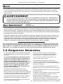
WARNING
All persons using this equipment must read, understand and follow all instructions. Failure to do so may result in serious injury or death. Do not use
this equipment unless you are properly trained.
Questions?
CALL
1.800.873.5242
It is crucial that the authorized person/user of this fall protection equipment read and understand
these instructions. In addition, it is the employer’s responsibility to ensure that all users are trained
in the proper use, inspection, and maintenance of fall protection equipment. Fall protection training
should be an integral part of a comprehensive safety program.
Proper use of fall arrest systems can save lives and reduce the potential of serious injuries from a
fall. The user must be aware that forces experienced during the arrest of a fall or prolonged suspension may cause bodily injury. Consult a physician if there is any question about the user’s ability
to use this product. Pregnant women and minors must not use this product.
Miller rope grabs are designed to protect working personnel from falls while allowing them
freedom of movement. Rope grabs move easily up and down vertical lifelines yet lock
instantly in the event of a free fall. Trailing models offer complete hands-free operation.
1.0 General Requirements
All warnings and instructions shall be provided
to authorized persons/users.
To minimize the potential for accidental
disengagement, a competent person must
ensure system compatibility.
All authorized persons/users must reference
the regulations governing occupational
safety, as well as applicable ANSI or
CSA standards. Please refer to product
ODEHOLQJIRULQIRUPDWLRQRQVSHFL¿F26+$
regulations, and ANSI and CSA standards
met by product.
Equipment must not be altered in any way.
Repairs must be performed only by the
manufacturer, or persons or entities authorized
in writing by the manufacturer.
Any product exhibiting deformities, unusual
wear, or deterioration must be immediately
discarded.
Proper precautions should always be taken to
remove any obstructions, debris, material, or
other recognized hazards from the work area
that could cause injuries or interfere with the
operation of the system.
Any equipment subject to a fall must be
removed from service.
The authorized person/user shall have a rescue
plan and the means at hand to implement it
when using this equipment.
All equipment must be inspected before
each use according to the manufacturer’s
instructions.
All equipment should be inspected by a
TXDOL¿HGSHUVRQRQDUHJXODUEDVLV
3
Never use fall protection equipment for
purposes other than those for which it was
designed. Fall protection equipment should
never be used for towing or hoisting.
U s e r In s tru c ti o n s - E n g l i s h
All synthetic material must be protected from
VODJKRWVSDUNVRSHQÀDPHVRURWKHUKHDW
sources. The use of heat resistant materials is
recommended in these applications.
Do not allow equipment to come in contact
with anything that will damage it including, but
not limited to, sharp, abrasive, rough or hightemperature surfaces, welding, heat sources,
electrical hazards, or moving machinery.
Never use natural materials (manila, cotton,
etc.) as part of a fall protection system.
Always check for obstructions below the work
area to make sure potential fall path is clear.
Environmental hazards should be considered
when selecting fall protection equipment.
Equipment must not be exposed to chemicals
which may produce a harmful effect. Polyester
should be used in certain chemical or acidic
environments. Use in highly corrosive or
caustic environments dictates a more frequent
inspection and servicing program to ensure the
integrity of the device is maintained. Contact
Miller Technical Services if in doubt.
Allow adequate fall clearance below the work
surface.
Never remove product labels, which include
important warnings and information for the
authorized person/user.
1.1 Warnings and Limitations
ROPE GRABS/WIRE ROPE GRABS
)RUXVHE\21(SHUVRQRQO\0D[LPXPFDSDFLW\LVOEVNJLQFOXGLQJWRROV²
'2127(;&(('7+,6:(,*+7
'RQRWXVHLIDQ\SDUWRIWKHGHYLFHDSSHDUVWREHGDPDJHG
Do not attempt to service the device or alter it in any way.
Attach the device to appropriate vertical lifelines only.
8VHRIWKLVSURGXFWLVQRWVXLWDEOHZKHQWKHXVHULVSRVLWLRQHGRQDQXQVWDEOHVXUIDFH¿QH
grain material, or particulate solids such as sand or coal.
0D[LPXPDUUHVWGLVWDQFHLQP
VERTICAL LIFELINES
0LOOHUYHUWLFDOOLIHOLQHVKDYHDPLQLPXPWHQVLOHVWUHQJWKRIOEVN1>26+$
requires a minimum tensile strength of 5,000 lbs. (22.2kN).]
/LIHOLQHVPXVWEHNHSWFOHDQ
Never allow the lifeline to become slack or to pass under or entwine around arms, legs,
neck, or any other obstacle.
'RQRWWLHNQRWVLQOLIHOLQHV
/LIHOLQHVPXVWEHDWWDFKHGLQGHSHQGHQWO\RIWKHZRUNLQJVXUIDFHDQGDQFKRUHGDERYHWKH
user to prevent a swing fall.
/LIHOLQHHORQJDWLRQFKDUDFWHULVWLFVURSHVWUHWFK ZLUHURSHVWUHWFK SYSTEM
A competent person must ensure the compatibility of all connections and that of the
system.
'RQRWXVHWKHV\VWHPLIWKHGHYLFHGRHVQRWORFNRQWRWKHOLIHOLQHRULIDQ\FRPSRQHQWLQ
the system does not operate properly.
The device and lifeline should be installed and used in such a manner as to reduce the
potential for a swing fall.
$OORZVXI¿FLHQWFOHDUDQFHLQWKHHYHQWRIDIUHHIDOO)RUV\QWKHWLFURSHOLIHOLQHVDGGIW
PRIIDOOFOHDUDQFHIRUHDFKIHHWPRIURSHDERYHWKHFRQQHFWLRQSRLQW,IDVKRFN
DEVRUEHULVXVHG\RXPXVWDOVRDOORZIRUDQDGGLWLRQDOIWPPD[LPXPHORQJDWLRQ
6\VWHPPXVWEHULJJHGWROLPLWWKHIUHHIDOOGLVWDQFHWRIHHWPRUOHVV
4
U s e r In s tru c ti o n s - E n g l i s h
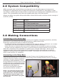
2.0 System Compatibility
Miller rope grabs and vertical lifelines are designed for use with Miller approved components.
Substitution or replacement with non-approved component combinations or subsystems or both
may affect or interfere with the safe function of each other and endanger the compatibility within the
system. This incompatibility may affect the reliability and safety of the total system.
$OZD\VXVH0LOOHUURSHJUDEVZLWKVSHFL¿HG0LOOHUYHUWLFDOOLIHOLQHVZLWKDPLQLPXPWHQVLOHVWUHQJWKRI
6,000 lbs. (27kN).
Model
/LIHOLQH
8172
5/16” (8mm) wire rope
8173
5/8” (16mm) synthetic rope
8174
5/8” (16mm) or 3/4” (19mm) synthetic rope
8175
5/8” (16mm) synthetic rope
8174C & 8174-Z7
5/8” (16mm) synthetic rope
8175C & 8175-Z7
5/8” (16mm) synthetic rope
3.0 Making Connections
Connecting to the Anchorage
The vertical lifeline must be attached to an anchor point capable of supporting 5,000 lbs. (22.2kN)
per worker or meet OSHA 1926.502 requirements for a safety factor of two.
Anchorage requirements based on ANSI are as follows:
)RUIDOODUUHVWV\VWHPVDQFKRUDJHVPXVWZLWKVWDQGDVWDWLFORDGRIOEVN1IRUQRQFHUWL¿HG
DQFKRUDJHVRUWZRWLPHVWKHPD[LPXPDUUHVWLQJIRUFHIRUFHUWL¿HGDQFKRUDJHV
:KHQPRUHWKDQRQHSHUVRQDOIDOODUUHVWV\VWHPLVDWWDFKHGWRDQDQFKRUDJHWKHDERYHDQFKRUDJH
strengths must be multiplied by the number of personal fall arrest systems attached to the anchorage.
Make sure connections are compatible in regards to size, strength, and shape. Never use an
anchor point which will not allow snap hook or carabiner keeper to close and lock, or which is
capable of causing a load to be applied to the keeper. Rope grabs are connected to the vertical
lifeline as per section 4.0, Installation.
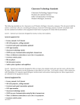
Connecting to the Body Wear
Rope grabs should be connected to either the back D-ring on the full-body harness (see Fig. 1)
using an approved lanyard, or to the front chest D-ring on the full-body harness (see Fig. 2) using a
connector, such as a locking carabiner.
(According to ANSI standards, a front
D-ring attachment element may be used
for fall arrest only in applications where
the personal fall arrest system limits the
maximum free fall distance to
2 ft. (0.6m) and limits the maximum
arrest force to 900 lbs. (4.0kN).)
127(7KHPD[LPXPODQ\DUGOHQJWK
is 3 ft. (.9m) for use with trailing rope
grabs (8172, 8173, and 8175 models).
7KHPD[LPXPODQ\DUGOHQJWKLVIW
(1.8m) for use with manual rope grabs
(8174 model).
Fig. 1
5
Fig. 2
U s e r In s tru c ti o n s - E n g l i s h
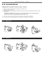
4.0 Installation
Models 8172 and 8173 (refer to Fig. 1 and 2)
1. Open the device by rotating the locking lever upward, and
2. Opening up the sideplate.
3. Place the device on the appropriate lifeline with the arrow pointing upwards toward the lifeline
anchor point.
:$51,1*1(9(5DWWDFKWKHGHYLFHRQWKHOLIHOLQHZLWKWKHDUURZSRLQWLQJGRZQZDUGLWZLOOQRWORFNRQWRWKHOLIHOLQHVKRXOGDIDOORFFXU
4. Close the device around the lifeline and rotate the locking lever downward.
5. Connect device to full-body harness (see Section 3.0, Making Connections).
Fig. 1 - Model 8172
2
1
4
3
Fig. 2 - Model 8173
2
1
4
3
6
U s e r In s tru c ti o n s - E n g l i s h
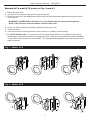
Models 8174 and 8175 (refer to Fig. 3 and 4)
1. Open the latch, and
2. Unscrew the locking thumbscrew to open the device.
3. Place the device on the appropriate lifeline with the arrow pointing upwards toward the lifeline
anchor point.
:$51,1*1(9(5DWWDFKWKHGHYLFHRQWKHOLIHOLQHZLWKWKHDUURZSRLQWLQJGRZQZDUGLWZLOOQRWORFNRQWRWKHOLIHOLQHVKRXOGDIDOORFFXU
4. Close the device around the lifeline, tighten thumbscrew, and
5. Close the latch.
6. Connect device to full-body harness (see section 3.0, Making Connections).
7. )RUPRGHOVRQO\ To reposition the rope grab on the lifeline, lift upward on the springloaded cam handle that connects the gripping cams. Slide the rope grab to the desired position
on the lifeline and release the cam handle. The spring-loaded gripping cams will keep the rope
grab in position.
Fig. 3 - Model 8174
2
4
3
1
5
Fig. 4 - Model 8175
4
1
2
5
3
7
U s e r In s tru c ti o n s - E n g l i s h
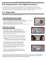
5.0 Inspection and Maintenance
Miller rope grabs and vertical lifelines are designed for today’s rugged work environments.
To maintain their service life and high performance, system components should be inspected
frequently. Inspect each product thoroughly before each use. Regular inspection by a competent
person for wear, damage or corrosion should be a part of your safety program.
5.1 Inspection
/$1<$5',163(&7,21
Before each use, visually inspect for the following:
ROPE GRABS/WIRE ROPE GRABS
,QVSHFWIRUSK\VLFDOGDPDJHFUDFNVZHDUDQGFRUURVLRQ
&KHFNFDPDQGVSULQJVPRGHOVIRUGDPDJHRUORVVRIWHQVLRQ
&KHFNSDZODQGORFNLQJPHFKDQLVPPRGHOV
%HVXUHWKDWDOOSDUWVPRYHIUHHO\ZLWKRXWKHVLWDWLRQ
&KHFNULYHWVIRUGDPDJHFUDFNVZHDURUFRUURVLRQ
,QVSHFWIRUPDOIXQFWLRQLQJFRPSRQHQWVEURNHQRUPLVVLQJVSULQJV
VERTICAL LIFELINES
5RSH/LIHOLQHV5RWDWLRQRIWKHURSHOLIHOLQHZKLOH
inspecting from end-to-end will bring to light any fuzzy,
ZRUQEURNHQRUFXW¿EHUV:HDNHQHGDUHDVIURPH[WUHPH
loads will appear as a noticeable change in original
diameter. The rope diameter should be uniform throughout,
following a short break-in period.
:LUH5RSH/LIHOLQHV:KLOHURWDWLQJWKHZLUHURSHOLIHOLQH
watch for cuts, frayed areas, or unusual wearing patterns
on the wire. Broken strands will separate from the body of
the lifeline.
&$87,21$OZD\VZHDUJORYHVZKHQLQVSHFWLQJD
ZLUHURSHOLIHOLQHEURNHQVWUDQGVFDQFDXVHLQMXU\
6QDS+RRNV&DUDELQHUV,QVSHFWFORVHO\IRUKRRNDQG
eye distortions, cracks, corrosion, or pitted surfaces.
The keeper (latch) should seat into the nose without
binding and should not be distorted or obstructed. The
NHHSHUVSULQJVKRXOGH[HUWVXI¿FLHQWIRUFHWR¿UPO\FORVH
the keeper. Keeper locks must prevent the keeper from
opening when the keeper closes.
7KLPEOHV7KHWKLPEOHPXVWEH¿UPO\VHDWHGLQWKHH\H
of the splice, and the splice should have no loose or cut
strands. The edges of the thimble must be free of sharp
edges, distortion, or cracks.
If inspection reveals a defect in condition, remove the device from service. Always remove
from service any equipment subject to a fall. Products removed from service should be
disposed of in a manner that prevents inadvertent further use.
8
U s e r In s tru c ti o n s - E n g l i s h
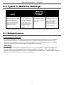
5.2 Types of Material Damage
MOLTEN
METAL OR
FLAME
HEAT
In excessive heat, rope/
webbing becomes brittle
and has a shriveled
brownish appearance.
Fibers will break when
ÀH[HG6KRXOGQRWEH
used above 180°F.
Change in color
usually appearing as
a brownish smear or
smudge. Transverse
cracks when rope/
webbing is bent over
a mandrel. Loss of
elasticity in rope/
webbing.
Rope/webbing strands
fuse together. Hard
shiny spots. Hard and
brittle feel.
Paint which penetrates
and dries restricts
PRYHPHQWRI¿EHUV
Drying agents and
solvents in some
paints will appear as
chemical damage.
Contact Miller Technical Service Department at 800-873-5242 if you have any questions about the above chart.
5.3 Maintenance
Cleaning and Storage
Basic care of all Miller Fall Protection equipment will prolong the durable life and will contribute
toward the performance of its vital safety function. Clean the equipment to remove any dirt,
corrosives, or contaminants. Store in a clean, dry area, free of exposure to fumes or corrosive
elements. Avoid excessive heat, steam, or long periods of sunlight.
Servicing
A record log of all inspection dates for this device must be maintained. Miller rope grabs and
wire rope grabs are not repairable and should be replaced if damaged. This system and all
components must be taken out of service if subjected to fall arrest forces. Contact Miller Technical
Services at 1-800-873-5242 if you have any questions.
9
Instructions D’utilisation - Français
Merci
Nous désirons vous remercier d’avoir acheté un équipement de Miller Fall Protection. Les produits
de marque Miller sont fabriqués selon des normes de qualité des plus rigoureuses, dans notre
XVLQHFHUWL¿pH,62%LHQHQWUHWHQXXQpTXLSHPHQW0LOOHU)DOO3URWHFWLRQV¶XWLOLVHGHV
années durant.
AVERTISSEMENT
Toutes les personnes qui utilisent cet équipement doivent lire, comprendre et
suivre toutes les instructions. Tout manquement à cette règle peut avoir pour conséquence des blessures graves ou la mort. Ne pas utiliser cet équipement à moins
d’avoir reçu une formation adéquate.
Des Questions?
APPELEZ
1.800.873.5242
Il est essentiel que la personne autorisée à utiliser cet équipement de protection contre les chutes
lise et comprenne ces instructions. De plus, il incombe à l’employeur de s’assurer que tous les utilisateurs sont formés à l’emploi, à l’inspection et à l’entretien adéquats de l’équipement de protection contre les chutes. La formation sur la protection contre les chutes devrait faire partie intégrante
d’un programme global de sécurité.
L’utilisation adéquate de systèmes d’arrêt de chute peut épargner des vies et réduire le risque de
blessures graves consécutives à une chute. L’utilisateur doit être sensibilisé au fait que les forces
subies lors d’un arrêt de chute ou d’une suspension prolongée peuvent causer des blessures
corporelles. Dans l’incertitude sur la capacité de la personne à utiliser ce produit, consulter un
médecin. Les femmes enceintes et les mineurs ne doivent pas utiliser ce produit.
/HVFRXOLVVHDX[GHVpFXULWp0LOOHUVRQWFRQoXVSRXUSURWpJHUOHVRXYULHUVFRQWUHOHVFKXWHV
WRXWHQOHXUSURFXUDQWODOLEHUWpGHPRXYHPHQW/HVFRXOLVVHDX[VHGpSODFHQWIDFLOHPHQWGH
KDXWHQEDVVXUOHVFkEOHVGHVpFXULWpYHUWLFDX[HWVHYHUURXLOOHQWLQVWDQWDQpPHQWHQFDVGH
FKXWHOLEUH/HVPRGqOHVGHWUDvQpHSURFXUHQWXQIRQFWLRQQHPHQWFRPSOHWPDLQVOLEUHV
1.0 Exigences Générales
Les avertissements et instructions devront être
mis à la disposition des personnes/utilisateurs
autorisés.
Pour minimiser le risque de décrochage
accidentel, une personne compétente doit
s’assurer de la compatibilité du système.
/HVSHUVRQQHVXWLOLVDWHXUVDXWRULVpVGRLYHQW
VHUHSRUWHUjODUpJOHPHQWDWLRQDSSOLFDEOHHQ
PDWLqUHGHVpFXULWpHQPLOLHXGHWUDYDLODLQVL
TX¶DX[QRUPHV$16,RX&6$SHUWLQHQWHV
9HXLOOH]YRXVUHSRUWHUDX[pWLTXHWWHVDSSRVpHV
sur les produits pour des informations plus
GpWDLOOpHVVXUOHVUqJOHPHQWV26+$DLQVL
TXHOHVQRUPHV$16,HW&6$DX[TXHOOHVFHV
produits sont conformes.
,OHVWLQWHUGLWGHPRGL¿HUO¶pTXLSHPHQWGH
quelque façon que ce soit.
'HVSUpFDXWLRQVGRLYHQWrWUHSULVHVD¿Q
d’éliminer de la zone de travail les obstacles,
débris, matériaux ou autres éléments présentant
un danger et qui pourraient causer des blessures
ou nuire au bon fonctionnement du système.
Tout équipement soumis à une chute doit être
mis hors service.
L’équipement doit être inspecté avant chaque
utilisation selon les directives du fabricant.
Les réparations doivent être effectuées
uniquement par le fabricant de l’équipement,
ou par des personnes ou entités autorisées par
écrit par le fabricant.
Tout produit déformé, anormalement usé ou
détérioré doit être immédiatement mis au rebut.
L’utilisateur doit posséder un plan de sauvetage
et avoir les moyens de le mettre en œuvre
lorsqu’il utilise cet équipement.
Ne jamais utiliser un équipement de protection
contre les chutes dans un but autre que celui
L’équipement doit être régulièrement inspecté
pour lequel il a été prévu. Ne jamais utiliser un tel
SDUXQHSHUVRQQHTXDOL¿pH
10 équipement pour remorquer ou lever une charge.
Instructions D’utilisation - Français
Les matériaux synthétiques doivent être protégés
contre le laitier (de soudure), les étincelles
FKDXGHVOHVÀDPPHVQXHVRXDXWUHVVRXUFHV
de chaleur. Dans de tels cas, on recommande
d’utiliser des matériaux résistant à la chaleur.
Ne jamais utiliser de matériaux naturels (chanvre
de Manille, coton, etc.) dans un système de
protection contre les chutes.
Dans la sélection d’équipement de protection
contre les chutes, on doit tenir compte des
risques environnementaux. On ne doit pas
exposer l’équipement aux produits chimiques
susceptibles de causer un effet nocif. Pour
utiliser l’équipement dans des environnements
hautement corrosifs ou caustiques, il faut mettre
en place un programme d’inspection et d’entretien
à intervalles rapprochés pour maintenir l’intégrité
du dispositif. En cas de doute, communiquer avec
les services techniques de Miller.
Éviter tout contact entre un équipement et un
objet susceptible de l’endommager, incluant
notamment, sans que la liste soit exhaustive :
des arêtes vives, une surface abrasive, rugueuse
ou à haute température, du matériel de soudage,
une source de chaleur, un appareil électrique
présentant un danger ou une machine mobile.
7RXMRXUVYpUL¿HUTX¶LOQ¶\DSDVG¶REVWDFOHVHQ
dessous de la zone de travail et que le trajet en
cas de chute est dégagé.
Éviter les risques de chute par balancement
en travaillant directement en-dessous du point
d’ancrage.
3UpYRLUXQHGLVWDQFHGHGpJDJHPHQWVXI¿VDQWH
en dessous de la surface de travail.
Ne jamais ôter une étiquette apposée sur un
produit; des informations et avertissements
importants y sont en effet inscrits à l’intention de
la personne/de l’utilisateur autorisé.
1.1 Avertissements et Limitations
COULISSEAUX DE SÉCURITÉ / CÂBLES MÉTALLIQUES DE SÉCURITÉ
¬XWLOLVHUSDU81(6(8/(SHUVRQQH/DFDSDFLWpPD[LPDOHHVWGHOENJ\
FRPSULVOHVRXWLOV²1(3$6'e3$66(5&(32,'6
1HSDVXWLOLVHUOHGLVSRVLWLIVLXQFRPSRVDQWTXHOFRQTXHVHPEOHDYRLUpWpHQGRPPDJp
1HSDVHQWUHSUHQGUHGHUpSDUHUĐDSSDUHLORXGHOHPRGL¿HUćXQHPDQLqUHTXHOFRQTXH
,QVWDOOHUOHGLVSRVLWLIXQLTXHPHQWVXUXQ¿OLQGHVpFXULWpYHUWLFDODSSURSULp
,OQ¶HVWSDVDSSURSULpG¶XWLOLVHUFHSURGXLWORUVTXHO¶XWLOLVDWHXUHVWSRVLWLRQQpVXUXQH
VXUIDFHLQVWDEOHFRPPHXQHSLOHGHPDWpULDX[VROLGHVHQSDUWLFXOHVRXHQJUDLQV¿QV
comme sable ou charbon.
'LVWDQFH'¶$UUHW0D[LQP
CÂBLES DE SÉCURITÉ VERTICAUX
/HVFkEOHVGHVpFXULWpYHUWLFDX[0LOOHURQWXQHIRUFHGHWUDFWLRQPLQLPDOHGHOE
N1>/¶26+$H[LJHXQHIRUFHGHWUDFWLRQPLQLPDOHGHOEN1@
*DUGHUOHVFkEOHVGHVpFXULWpSURSUHV
)DLUHHQVRUWHTXHOHFkEOHGHVpFXULWpQHGHYLHQQHSDVOkFKH
Ne pas faire passer le câbleGHVpFXULWpHQWUHRXDXWRXUG¶XQEUDVG¶XQHMDPEHGXFRXGH
l’utilisateur ou de tout autre obstacle.
1HSDVIDLUHGHQ°XGVGDQVOHVFkEOHVGHVpFXULWp
/HVFkEOHVGHVpFXULWpGRLYHQWrWUHDWWDFKpVLQGpSHQGDPPHQWGHO¶DLUHGHWUDYDLOHWDQFUpV
DXGHVVXVGHO¶XWLOLVDWHXUSRXUpYLWHUOHVFKXWHVSDUEDODQFHPHQW
&DUDFWpULVWLTXHVG¶pORQJDWLRQGHVFkEOHVGHVpFXULWpH[WHQVLRQGHVFRXOLVVHDX[ H[WHQVLRQGHVFkEOHVPpWDOOLTXHV SYSTÈME
8QHSHUVRQQHFRPSpWHQWHGRLWV¶DVVXUHUGHODFRPSDWLELOLWpGHWRXVOHVUDFFRUGVHWGH
celle du système.
1HSDVXWLOLVHUFHV\VWqPHV¶LOQ¶HVWSDVSRVVLEOHG¶REWHQLUXQEORFDJHVXUOHFkEOH de
VpFXULWpRXVLXQFRPSRVDQWTXHOFRQTXHGXV\VWqPHQHIRQFWLRQQHSDVFRUUHFWHPHQW
/HGLVSRVLWLIHWOHFkEOHGHVpFXULWpGRLYHQWrWUHLQVWDOOpVHWXWLOLVpVGHPDQLqUHjUpGXLUHOH
risque de chute par balancement.
3UpYRLUXQGpJDJHPHQWVXI¿VDQWHQFDVGHFKXWHOLEUH3RXUOHVFkEOHVV\QWKpWLTXHV
DMRXWHUSLPPGHGLVWDQFHGHGpJDJHPHQWSRXUFKDTXHORQJXHXUGHSLPP
de câble au-dessus du point de raccordement. Si l’on utilise un amortisseur de chocs, on
GRLWpJDOHPHQWDOORXHUXQHpORQJDWLRQPD[LPDOHVXSSOpPHQWDLUHGHòSLPP
/HV\VWqPHGRLWrWUHLQVWDOOpGHIDoRQjOLPLWHUODGLVWDQFHGHFKXWHOLEUHjSLPPRX
moins.
11
Instructions D’utilisation - Français
2.0 Compatibilité du Système
Les coulisseaux de sécurité et les câbles verticaux sont conçus pour être utilisés avec des
composants Miller approuvés. Les substitutions ou les remplacements par des combinaisons de
composants ou de sous-systèmes non approuvés peuvent nuire à leur sécurité de fonctionnement
réciproque et ainsi remettre en cause la compatibilité des éléments du système. Cette
LQFRPSDWLELOLWpSHXWQXLUHjODVpFXULWpHWjOD¿DELOLWpGHO¶HQVHPEOHGXV\VWqPH
Toujours utiliser des coulisseaux de sécurité Miller avec des câbles de sécurité verticaux Miller avec
force de traction minimale de 6000 lb (27 kN).
Modèle
&kEOHGH6pFXULWp
8172
Câble métallique de 5/16” (8 mm)
8173
Câble synthétique de 5/8” (16 mm)
8174
Câble synthétique de 5/8” (16 mm) ou de 3/4” (19 mm)
8175
Câble synthétique de 5/8” (16 mm)
8174C & 8174-Z7
Câble synthétique de 5/8” (16 mm)
8175C & 8175-Z7
Câble synthétique de 5/8” (16 mm)
3.0 Établissement de Raccords
Raccordement à L’ancrage
Le câble de sécurité vertical doit être attaché à un point d’ancrage pouvant supporter 5000 lb (22.2
kN) par ouvrier ou satisfaire aux exigences 1926.502 de l’OSHA pour un facteur de sécurité de deux.
Les exigences ANSI qui s’appliquent aux ancrages sont les suivantes :
/¶DQFUDJHQRQFHUWL¿pG¶XQGLVSRVLWLIDQWLFKXWHGRLWVXSSRUWHUXQHFKDUJHVWDWLTXHGHOEN1
WDQGLVTX¶XQDQFUDJHFHUWL¿pGRLWVXSSRUWHUGHX[IRLVODIRUFHPD[LPDOHPLVHHQMHXORUVGHO¶DUUrWG¶XQH
chute.
/RUVTXHSOXVLHXUVGLVSRVLWLIVDQWLFKXWHLQGLYLGXHOVVRQW¿[pVjXQPrPHDQFUDJHOHVUpVLVWDQFHV
d’ancrage ci-dessus doivent être multipliées par le nombre de dispositifs anti-chute rattachés à l’ancrage.
S’assurer que les raccordements sont compatibles quant aux dimensions, à la force et à la forme.
Ne jamais utiliser un point d’ancrage qui empêche la boucle à pression ou le loquet de mousqueton
de se fermer et de se verrouiller, ou qui peut faire en sorte qu’une charge soit appliquée au loquet.
Les coulisseaux de sécurité sont raccordés au câble vertical suivant la section 4.0 – Installation.
Raccordement au Dispositif de Protection
Les coulisseaux de sécurité doivent être raccordés à l’anneau dorsal en D sur le harnais intégral
(voir Fig. 1) à l’aide d’une longe approuvée, ou à l’anneau frontal en D sur le harnais intégral (voir
Fig. 2) à l’aide d’un connecteur, tel qu’un mousqueton à verrou. (Selon les normes de l’ANSI,
on peut utiliser un élément d’attache
d’anneau frontal en D pour arrêt de
chute uniquement dans les applications
où le système d’arrêt de chute individuel
limite la distance maximale de chute
libre à 2 pi (0.6 m) et la force d’arrêt
maximale à 900 lb (4.0 kN).
127$/DORQJXHXUPD[LPDOHG¶XQH
longe est de 3 pi (0.9 m) pour utilisation
DYHFGHVFRXOLVVHDX[GHVpFXULWpGH
WUDvQpHPRGqOHVHW
/DORQJXHXUPD[LPDOHG¶XQHORQJHHVW
GHSLPSRXUXWLOLVDWLRQDYHF
GHVFRXOLVVHDX[GHVpFXULWpPDQXHOV
(modèles 8174).
12
Fig. 1
Fig. 2
Instructions D’utilisation - Français
4.0 Installation
Modèles 8172 et 8173 (se reporter aux Fig. 1 et 2)
1. Ouvrir le dispositif en faisant pivoter le levier verrouillant vers le haut; et
2. Ouvrir la plaque latérale.
3ODFHUOHGLVSRVLWLIVXUOHFkEOHGHVpFXULWpDSSURSULpODÀqFKHSRLQWDQWYHUVOHKDXWHQGLUHFWLRQ
du point d’ancrage du câble.
0,6((1*$5'(4XDQGRQDWWDFKHOHGLVSRVLWLIDXFjEOHGHVpFXULWp1(-$0$,6
IDLUHSRLQWHUODÀqFKHYHUVOHEDVHQFDVGHFKXWHLOQHSRXUUDLWSDVVHYHUURXLOOHU
sur le câble.
4. Fermer le dispositif autour du câble de sécurité et faire pivoter le levier verrouillant vers le bas.
5. Raccorder le dispositif au harnais intégral ( Voir la Section 3.0 – Établissement de Raccords ).
Fig. 1 - Modèle 8172
2
1
4
3
Fig. 2 - Modèle 8173
2
1
4
3
13
Instructions D’utilisation - Français
Modèles 8174 et 8175 (se reporter aux Fig. 3 et 4)
1. Ouvrir le loquet, et
2. Dévisser la vis de serrage pour ouvrir le dispositif
3ODFHUOHGLVSRVLWLIVXUOHFkEOHGHVpFXULWpDSSURSULpODÀqFKHSRLQWDQWYHUVOHKDXWHQGLUHFWLRQ
du point d’ancrage du câble.
0,6((1*$5'(4XDQGRQDWWDFKHOHGLVSRVLWLIDXFjEOHGHVpFXULWp1(-$0$,6
IDLUHSRLQWHUODÀqFKHYHUVOHEDVHQFDVGHFKXWHLOQHSRXUUDLWSDVVHYHUURXLOOHU
sur le câble.
4. Fermer le dispositif autour du câble de sécurité, serrer la vis, et
5. Fermer le loquet.
6. Raccorder le dispositif au harnais intégral ( Voir la Section 3.0 – Établissement de raccords ).
7. 3RXUPRGqOHVVHXOHPHQWPour replacer le coulisseau de sécurité sur le càble, soulever
la poignée à ressort qui se raccorde aux cames d’accrochage. Faire glisser le coulisseau à la
position voulue sur le câble et relâcher la poignée. Les cames d’accrochage maintiennent le
coulisseau en place.
Fig. 3 - Modèle 8174
2
4
3
1
5
Fig. 4 - Modèle 8175
4
1
2
5
3
14
Instructions D’utilisation - Français
5.0 Inspection et Entretien
Les coulisseaux de sécurité et les câbles verticaux sont conçus pour les environnements de travail
GLI¿FLOHVG¶DXMRXUG¶KXL$¿QGHPDLQWHQLUOHXUGXUpHHWOHXUUHQGHPHQWpOHYpRQGRLWLQVSHFWHU
fréquemment les composants du système. Inspecter à fond chaque produit avant chaque utilisation.
Votre programme de sécurité doit comprendre une inspection régulière par une personne
compétente, pour voir s’il n’y a pas d’usure, de dommages ou de corrosion.
5.1 Inspection
$1<$5',163(&7,21
Avant chaque utilisation, inspecter visuellement l’équipment comme suit:
COULISSEAUX DE SÉCURITÉ / CÂBLES MÉTALLIQUES
DE SÉCURITÉ
9pULILHUSRXUYRLUV¶LOQ¶\DSDVGHGRPPDJHVSK\VLTXHVGHFUDTXHOXUHV
d’usure ou de corrosion.
9pULILHUOHVFOLTXHWVHWOHVUHVVRUWV0RGqOHVHWSRXUYRLUV¶LOQ¶\D
pas de dommages ou de perte de tension.
9pULILHUOHVFOLTXHWVHWOHPpFDQLVPHGHYHUURXLOODJH0RGqOHVHW
6¶DVVXUHUTXHWRXWHVOHVSDUWLHVVHGpSODFHQWOLEUHPHQWHWVDQVKpVLWDWLRQ
9pULILHUOHVULYHWVSRXUYRLUV¶LOQ¶\DSDVGHGRPPDJHVGHFUDTXHOXUHVG¶XVXUHRXGHFRUURVLRQ
9pULILHUSRXUYRLUV¶LOQ¶\DSDVGHFRPSRVDQWVTXLIRQFWLRQQHQHQWPDOQLGHUHVVRUWVEULVpVRX
manquants.
CÂBLES DE SÉCURITÉ VERTICAUX
&kEOHVGHVpFXULWp3HQGDQWO¶LQVSHFWLRQLQWpJUDOHGXFkEOHGH
sécurité, le fait de tourner ce dernier permettra de constater s’il y
DGHV¿EUHVÀRXHVXVpHVEULVpHVRXFRXSpHV8QH]RQHDIIDLEOLH
sous une charge extrême se remarque par un changement notable
du diamètre (par rapport à celui d’origine). Après une brève période
de rodage, le diamètre de la corde doit être uniforme d’un bout à
l’autre.
&kEOHVGHVpFXULWpPpWDOOLTXHV(QIDLVDQWWRXUQHUOHFkEOH
PpWDOOLTXHYpUL¿HUODSUpVHQFHGHFRXSXUHVG¶pUDLOOXUHVRXG¶XVXUH
inhabituelle. Les brins sectionnés se détachent du câble.
$77(17,217RXMRXUVSRUWHUGHVJDQWVTXDQGRQLQVSHFWH
XQFkEOHGHVpFXULWpPpWDOOLTXHOHVEULQVEULVpVSHXYHQW
FDXVHUGHVEOHVVXUHV
%RXFOHVjSUHVVLRQPRXVTXHWRQV9pUL¿HUVRLJQHXVHPHQWOH
FURFKHWHWO¶RHLOSRXUYRLUV¶LOQ¶\DSDVGHGpIRUPDWLRQVGH¿VVXUHV
de corrosion ou de corrosion par piqûres. Le système d’ouverture
(avec verrou) doit s’insérer dans le nez sans se coincer et ne doit
être ni déformé, ni bloqué par un obstacle. Le ressort du système
G¶RXYHUWXUHGRLWH[HUFHUXQHIRUFHVXI¿VDQWHSRXUXQHERQQH
fermeture. Les verrous d’un système d’ouverture doivent empêcher
ce dernier de s’ouvrir lors de la fermeture.
&RVVHV8QHFRVVHGRLWrWUHVROLGHPHQW¿[pHGDQVO¶RHLOGH
O¶pSLVVXUHHWDXFXQ¿OGHFHWWHpSLVVXUHQHGRLWrWUHGpWDFKpQL
coupé. Les rebords de la cosse doivent être exempts d’arêtes vives,
GHGpIRUPDWLRQVRXGH¿VVXUHV
6LO¶LQVSHFWLRQUpYqOHXQHGpIHFWXRVLWpGHFRQGLWLRQUHWLUHUOHGLVSRVLWLIGXVHUYLFH7RXMRXUV
UHWLUHUGXVHUYLFHWRXWpTXLSHPHQWVXMHWjXQHFKXWH/HVSURGXLWVUHWLUpVGXVHUYLFHGRLYHQW
rWUHpOLPLQpVGHPDQLqUHjHPSrFKHUXQHXWLOLVDWLRQXOWpULHXUHSDULQDGYHUWDQFH
15
Instructions D’utilisation - Français
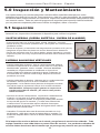
5.2 Types de Dommages Matériels
MÉTAL
FONDU OU
FLAMME
CHALEUR
PRODUITS
CHIMIQUES
Exposée à une chaleur
excessive, une corde/une
sangle devient cassante
comme du verre, se
ratatine et prend une
couleur brunâtre.
/HV¿EUHVVHFDVVHQW
ORUVTX¶RQOHVÀpFKLW
Ne pas utiliser à une
température supérieure à
180°F (82°C).
Le changement de
couleur se présente
habituellement sous la
forme d’une maculation
ou d’une empreinte
brunâtre. Fissures
transversales lorsqu’on
plie le cordage/la
sangle sur un mandrin.
Perte d’élasticité dans
le cordage/la sangle.
/HV¿OVGHFRUGDJH
sangle fusionnent.
Points durs brillants.
Dur et cassant au
toucher.
PEINTURES
ET SOLVANTS
La peinture qui durcit
après avoir pénétré nuit
au bon déplacement
GHV¿EUHV/HVDJHQWV
de séchage et les
solvants contenus dans
certaines peintures
produisent des
dommages semblables
à ceux dus à des
produits chimiques.
Pour toute question sur le tableau ci-dessus, contacter le Service technique Miller au 800-873-5242.
5.3 Entretien
Nettoyage et Entreposage
Grâce à un entretien de base, on prolonge la durée de vie des équipements Miller Fall Protection et on
leur permet de mieux remplir leur fonction de sécurité vitale. Nettoyer l’équipement pour enlever toute
saleté, toute corrosion ou tous contaminants. Entreposer dans un endroit propre et sec, à l’abri des
vapeurs et d’éléments corrosifs. Éviter la chaleur excessive, la vapeur ou de longues périodes de
soleil.
Entretien
On doit tenir un registre de toutes les dates d’inspection pour ce dispositif. Les coulisseaux
de sécurité et les câbles Miller ne sont pas réparables et doivent être remplacés s’ils sont
endommagés. On doit retirer du service le système et tous ses composants s’ils ont subi
des forces d’arrêt de chute. Pour toute question à ce sujet, communiquer avec les Services
techniques de Miller, au 1 (800) 873-5242.
16
Instrucciones Para El Usuario - Español
Gracias
Le agradecemos su compra de equipo anticaídas Miller. Los productos de la marca Miller son
manufacturados para cumplir con las más altas normas de calidad en nuestra fábrica, la cual
SRVHHODFHUWL¿FDFLyQ,62&XLGDGRVFRPRHVGHELGRORVHTXLSRVDQWLFDtGDV0LOOHUOH
servirán muchos años.
ADVERTENCIA
Toda persona que use este equipo debe leer, comprender y seguir cabalmente todas las instrucciones. No hacerlo podría tener como consecuencia lesiones graves
o mortales. No use este equipo si no ha sido debidamente entrenado.
¿Consultas?
LLAMAR AL
1.800.873.5242
Es fundamental que la persona o usuario autorizado de este equipo anticaídas lea y comprenda las
presentes instrucciones. Además, es responsabilidad del empleador que todos los usuarios hayan
recibido capacitación para usar, inspeccionar y dar el debido mantenimiento al equipo anticaídas.
La capacitación anticaídas debe ser parte integral de un programa completo de seguridad.
La utilización correcta de los sistemas de detención de caídas puede salvar vidas y disminuir las
posibilidades de lesiones graves en caso de una caída. Los usuarios deben estar conscientes de
que las fuerzas ejercidas para detener una caída o durante una suspensión prolongada pueden
causar lesiones. Consulte a un médico en caso de duda sobre la capacidad del usuario para emplear este producto. Las mujeres embarazadas y los niños no deben usar este producto.
/RVVXMHWDFXHUGDV0LOOHUHVWiQIDEULFDGRVSDUDSURWHJHUFRQWUDFDtGDVDOSHUVRQDOSHUPLWLpQGROHV
DOPLVPRWLHPSROLEHUWDGGHPRYLPLHQWR/RVVXMHWDFXHUGDVVHGHVSOD]DQFRQIDFLOLGDGKDFLD
DUULED\KDFLDDEDMRSRUODVFXHUGDVVDOYDYLGDVSHURVHDVHJXUDQLQVWDQWiQHDPHQWHHQFDVRGH
XQDFDtGDOLEUH/RVPRGHORVVHJXLGRUHVSHUPLWHQXQDFRPSOHWDOLEHUWDGGHPDQRV
1.0 Requisitos Generales
$¿QGHUHGXFLUDOPtQLPRODVSRVLELOLGDGHV
de un desenganche accidental, una persona
competente debe garantizar la compatibilidad
del sistema.
Deben suministrarse a las personas y
usuarios autorizados todas las advertencias e
instrucciones.
Todas las personas y usuarios autorizados
deben consultar los reglamentos de
seguridad laboral y las normas ANSI o
&6$TXHFRUUHVSRQGDQ/DVHWLTXHWDVGHO
producto contienen información sobre los
UHJODPHQWRV26+$\ODVQRUPDV$16,\
CSA que cumple el producto.
El equipo no debe ser alterado de ninguna forma.
Las reparaciones deben ser efectuadas
exclusivamente por el fabricante del equipo o
bien por personas o entidades autorizadas por
escrito por el fabricante.
Todo producto con deformidades, desgaste
anormal o deterioro debe ser desechado de
inmediato.
Siempre deben tomarse las debidas
precauciones al retirar del área de trabajo
obstrucciones, basura, material y otros peligros
reconocidos que pudieran causar lesiones o
interferir en el funcionamiento del sistema.
Todo equipo sometido a una caída debe ser
puesto fuera de servicio.
Todo el equipo debe ser inspeccionado
visualmente antes de cada uso de conformidad
con las instrucciones del fabricante.
El usuario debe contar con un plan y medios de
rescate a mano para poder aplicarlos al usar
este equipo.
Todo el equipo debe ser inspeccionado con
UHJXODULGDGSRUXQDSHUVRQDFDOL¿FDGD
-DPiVORXWLOLFHSDUD¿QHVGLVWLQWRVDOSUR\HFWDdo. No use jamás el equipo para remolcar o izar
objetos.
17
Instrucciones Para El Usuario - Español
Debe protegerse todo el material sintético con
el objeto de mantenerlo alejado de escorias,
chispas calientes, llamas y otras fuentes de
calor. Para tales usos se recomienda el uso de
materiales resistentes al calor.
Jamás use materiales naturales (cáñamo
de Manila, algodón, etc.) como parte de un
sistema de protección contra caídas.
Al seleccionar equipo anticaídas deben tomarse
en cuenta los riesgos medioambientales.
No debe exponerse el equipo a sustancias
químicas que puedan producir un efecto
perjudicial. El uso del equipo en entornos
muy corrosivos o cáusticos exige un programa
de inspecciones y servicio más frecuentes
para garantizar la integridad continuada del
dispositivo. Si tiene dudas, comuníquese con el
Depto. de Servicio Técnico de Miller.
No permita que la cuerda o el tejido entren
en contacto con cualquier cosa que pueda
GDxDUORVFRPRVXSHU¿FLHVD¿ODGDVDEUDVLYDV
ásperas o a alta temperatura, soldadura,
fuentes de calor, peligros eléctricos o
maquinaria en movimiento.
Siempre revise para ver si hay obstrucciones abajo
GHOiUHDGHWUDEDMRFRQHO¿QGHDVHJXUDUVHGHTXH
esté despejada la trayectoria de una posible caída.
Evite los peligros de una caída columpiada;
trabaje abajo del punto de anclaje.
Deje una distancia segura de caída adecuada
DEDMRGHODVXSHU¿FLHGHWUDEDMR
Nunca desprenda etiquetas de los productos, las
cuales pueden incluir importantes advertencias e
información para la persona o usuario autorizado.
1.1 Advertencias y Limitaciones
SUJETACUERDAS (CUERDA SINTÉTICA / CUERDA DE ALAMBRE)
Deben ser usados por UNA sola persona./DFDSDFLGDGPtQLPDHVOENJ
LQFOXLGDVODVKHUUDPLHQWDV²12(;&('$(67(3(62
1RXVHHOHTXLSRVLFXDOTXLHUSLH]DGHOGLVSRVLWLYRSDUHFHHVWDUGDxDGD
1RLQWHQWHUHSDUDUHOGLVSRVLWLYRQLPRGL¿FDUORGHQLQJXQDPDQHUD
,QVWDOHHOGLVSRVLWLYRVRODPHQWHHQFXHUGDVVDOYDYLGDVYHUWLFDOHVDSURSLDGDV
1RHVFRQYHQLHQWHXVDUHVWHHTXLSRFXDQGRHOXVXDULRHVWpSDUDGRVREUHXQDVXSHU¿FLH
LQHVWDEOHPDWHULDOGHJUDQR¿QRRPDWHULDOHVVyOLGRVHQSDUWtFXODVWDOFRPRDUHQDRFDUEyQ
'LVWDQFLD'H'HWHQFLyQ0i[ 39 in. (1m)
CUERDAS SALVAVIDAS VERTICALES
/DVFXHUGDVVDOYDYLGDV0LOOHUWLHQHQOEN1GHUHVLVWHQFLDPtQLPDDODWUDFFLyQ
>26+$UHTXLHUHOEN1GHUHVLVWHQFLDPtQLPDDODWUDFFLyQ@
'HEHQPDQWHQHUVHOLPSLDVODVFXHUGDVVDOYDYLGDV
1RSHUPLWDTXHVHSRQJDKROJDGDODFXHUGDVDOYDYLGDV
Nunca permita que una cuerda salvavidas pasen por abajo de los brazos, piernas, cuello o
QLQJ~QREVWiFXORHQWUHHOORVQLVHHQUHGHQDOUHGHGRUGHORVPLVPRV
1RKDJDQXGRVHQODVFXHUGDVVDOYDYLGDV
/DVFXHUGDVVDOYDYLGDVGHEHQVXMHWDUVHGHPDQHUDLQGHSHQGLHQWHDODVXSHU¿FLHGHWUDEDMR
\GHEHQDQFODUVHDUULEDGHOXVXDULRFRPRSUHYHQFLyQSDUDXQDFDtGDFROXPSLDGD
&DUDFWHUtVWLFDVGHDODUJDPLHQWRGHODVFXHUGDVVDOYDYLGDVHVWLUDPLHQWRGHODFXHUGD
VLQWpWLFD HVWLUDPLHQWRGHODFXHUGDGHDODPEUH SISTEMA
8QDSHUVRQDFRPSHWHQWHGHEHJDUDQWL]DUODFRPSDWLELOLGDGGHWRGDVODVFRQH[LRQHV\GHO
sistema.
1RXVHHVWHHTXLSRVLHOGLVSRVLWLYRQRTXHGDEORTXHDGRHQODFXHUGDVDOYDYLGDVRVL
cualquier componente del sistema no funciona en forma debida.
(VWHGLVSRVLWLYR\ODFXHUGDVDOYDYLGDVGHEHQLQVWDODUVH\XVDUVHGHWDOPDQHUDTXHVH
UHGX]FDODSRVLELOLGDGGHXQDFDtGDFROXPSLDGD
'HMHVX¿FLHQWHGLVWDQFLDVHJXUDGHFDtGDFRPRSUHYHQFLyQHQFDVRGHXQDFDtGDOLEUH
3DUDODVFXHUGDVVDOYDYLGDVVLQWpWLFDVDJUHJXHSLHPGHGLVWDQFLDVHJXUDGH
FDtGDSRUFDGDSLHVPGHFXHUGDDUULEDGHOSXQWRGHFRQH[LyQ6LVHHPSOHDXQ
DPRUWLJXDGRUGHLPSDFWRDJUHJXHSLHVPGHDODUJDPLHQWRPi[LPRDGLFLRQDO
(OVLVWHPDGHEHHVWDUDSDUHMDGRGHWDOPDQHUDTXHOLPLWHODGLVWDQFLDGHFDtGDOLEUHDSLHV
(1.8 m) o menos.
18
Instrucciones Para El Usuario - Español
2.0 Compatibilidad del Sistema
Los sujetacuerdas y cuerdas salvavidas verticales Miller están fabricados para usarse con
componentes aprobados por dicha compañía. La sustitución o reemplazo de dichos componentes
con combinaciones no aprobadas de componentes o subsistemas, puede afectar o interferir en el
funcionamiento seguro de cada componente y poner en peligro la compatibilidad dentro del sistema.
(VWDLQFRPSDWLELOLGDGSXHGHDIHFWDUOD¿DELOLGDG\VHJXULGDGGHOVLVWHPDWRWDO
6LHPSUHXVHVXMHWDFXHUGDVFRQODVFXHUGDVVDOYDYLGDV0LOOHUHVSHFL¿FDGDVFRQOEN1GH
resistencia mínima a la tracción.
Modelo
Cuerda Salvavidas
8172
Cuerda de alambre de 5/16” (8 mm)
8173
Cuerda sintética de 5/8” (16 mm)
8174
Cuerda sintética de 5/8” (16 mm) o 3/4” (19 mm)
8175
Cuerda sintética de 5/8” (16 mm)
8174C & 8174-Z7
Cuerda sintética de 5/8” (16 mm)
8175C & 8175-Z7
Cuerda sintética de 5/8” (16 mm)
3.0 Realización de Conexiones
Forma de efectuar la conexión al anclaje
La cuerda salvavidas vertical debe ser unida a un punto de anclaje capaz de soportar 5,000 libras
(22.2 kN) por trabajador, o cumplir los requisitos de la norma OSHA 1926.502 con un factor de
seguridad de dos. Los requisitos para el anclaje basados en las normas ANSI son como sigue:
Para los sistemas de detención de caídas, los anclajes deben poder soportar una carga estática de
OEN1HQHOFDVRDQFODMHVQRFHUWL¿FDGRVRGRVYHFHVODIXHU]DGHGHWHQFLyQPi[LPDHQHO
FDVRGHDQFODMHVFHUWL¿FDGRV
&XDQGRVHVXMHWDPiVGHXQVLVWHPDSHUVRQDOGHGHWHQFLyQGHFDtGDVDXQDQFODMHVHGHEHQ
multiplicar las fuerzas de anclaje indicadas arriba por el número de sistemas sujetados a dicho anclaje.
Asegúrese de que las conexiones sean compatibles en tamaño, resistencia y forma. Nunca use
un punto de anclaje que no permita que cierre o se asegure el gancho de resorte o el linguete del
mosquetón, o que pueda causar que se aplique una carga en dicho linguete. Los sujetacuerdas se
conectan a la cuerda salvavidas vertical de conformidad con la sección 4.0, “Instalación”.
Forma de efectuar la conexión al aparejo del cuerpo
El sujetacuerdas debe conectarse ya sea al anillo “D” posterior del arnés de cuerpo entero (ver
¿JPHGLDQWHXQDFXHUGDGHVHJXULGDGDSUREDGDRDODQLOOR³'´SHFWRUDOGHGLFKRDUQpVYHU
¿JPHGLDQWHXQFRQHFWRUFRPRXQ
mosquetón asegurador. (De conformidad
con las normas ANSI, un elemento de unión
de anillo “D” frontal puede usarse para
detención de caídas sólo en aplicaciones en
las cuales el sistema personal de detención
de caídas limita la distancia máxima de
caída libre a 2 pies (0.6 m) y limita la fuerza
máxima de detención a 900 lb (4.0 kN).
127$/DORQJLWXGPi[LPDGHODFXHUGD
de seguridad es 3 pies (0.9 m) para usarse
con sujetacuerdas seguidores (los modelos
\/DORQJLWXGPi[LPD
GHODFXHUGDGHVHJXULGDGHVSLHVP
para usarse con sujetacuerdas manuales (el
modelo 8174).
Fig. 1
19
Fig. 2
Instrucciones Para El Usuario - Español
4.0 Instalación
Modelos 8172 y 8173 (ver Àgs. 1 y 2)
1. Abra el dispositivo; para ello, gire hacia arriba la palanca de aseguramiento.
2. Abra la placa lateral.
&RORTXHHOGLVSRVLWLYRHQODFXHUGDVDOYDYLGDVFRQODÀHFKDDSXQWDQGRKDFLDDUULEDKDFLDHO
punto de anclaje de la cuerda salvavidas.
$'9(57(1&,$181&$XQDHOGLVSRVLWLYRDODFXHUGDVDOYDYLGDVFRQODÀHFKD
DSXQWDQGRKDFLDDEDMRGHORFRQWUDULRHOGLVSRVLWLYRQRVHD¿DQ]DHQGLFKDFXHUGD
VLVXFHGHXQDFDtGD
4. Cierre el dispositivo alrededor de la cuerda salvavidas y gire hacia abajo la palanca de
aseguramiento.
5. Conecte el dispositivo al arnés de cuerpo entero (vea la sección 3.0, “Realización de conexiones”).
Fig. 1 - Modelo 8172
2
1
4
3
Fig. 2 - Modelo 8173
2
1
4
3
20
Instrucciones Para El Usuario - Español
Modelos 8174 y 8175 (ver Àgs. 3 y 4)
1. Abra el pestillo.
2. Desenrosque el tornillo de apriete manual para abrir el dispositivo.
&RORTXHHOGLVSRVLWLYRHQODFXHUGDVDOYDYLGDVFRQODÀHFKDDSXQWDQGRKDFLDDUULEDKDFLDHO
punto de anclaje de la cuerda salvavidas.
$'9(57(1&,$181&$XQDHOGLVSRVLWLYRDODFXHUGDVDOYDYLGDVFRQODÀHFKD
DSXQWDQGRKDFLDDEDMRGHORFRQWUDULRHOGLVSRVLWLYRQRVHD¿DQ]DHQGLFKDFXHUGD
VLVXFHGHXQDFDtGD
4. Cierre el dispositivo alrededor de la cuerda salvavidas y apriete el tornillo de apriete manual.
5. Cierre el pestillo.
6. Conecte el dispositivo al arnés de cuerpo entero (vea la sección 3.0, “Realización de Conexiones”).
7. 6yORORVPRGHORVPara cambiar la posición del sujetacuerda en la cuerda salvavidas, levante la manija que conecta las levas de sujeción. Deslice el sujetacuerda a la posición deseada
en la cuerda salvavidas y suelte la manija de las levas. Las levas sujetadoras de resorte mantienen el sujetacuerda en su posición.
Fig. 3 - Modelo 8174
2
4
3
1
5
Fig. 4 - Modelo 8175
4
1
2
5
3
21
Instrucciones Para El Usuario - Español
5.0 Inspección y Mantenimiento
Los sujetacuerdas y las cuerdas salvavidas verticales Miller están fabricadas para los rudos
ambientes de trabajo de hoy en día. Para mantener su vida útil y gran desempeño, los componentes
del sistema deben inspeccionarse con frecuencia. Inspeccione meticulosamente cada producto cada
vez antes de usarlos. Debe ser parte del programa de seguridad una inspección habitual realizada
por una persona competente para buscar indicios de desgaste, daños o corrosión.
5.1 Inspección
/$1<$5',163(&7,21
$QWHVGHOXVRLQVSHFFLyQHYLVXDOPHQWHHOGLVSRVLWLYRSDUDYHUL¿FDUORVLJXLHQWH
SUJETACUERDAS (CUERDA SINTÉTICA / CUERDA DE ALAMBRE)
,QVSHFFLyQHORVSDUDYHUVLWLHQHQGDxRVJULHWDVGHVJDVWH\FRUURVLyQ
5HYLVHODOHYD\ORVUHVRUWHVPRGHORV\SDUDYHUVLWLHQHQGDxRVR
pérdida de tensión.
5HYLVHHOWULQTXHWH\HOPHFDQLVPRGHDVHJXUDPLHQWRPRGHORV\
$VHJ~UHVHGHTXHWRGDVODVSLH]DVVHPXHYDQOLEUHPHQWHVLQGHWHQHUVH
5HYLVHORVUHPDFKHVSDUDYHUVLWLHQHQGDxRVJULHWDVGHVJDVWHRFRUURVLyQ
,QVSHFFLRQHSDUDYHUVLKD\FRPSRQHQWHVIXQFLRQDQGRPDORUHVRUWHVURWRVR
faltantes.
CUERDAS SALVAVIDAS VERTICALES
&XHUGDVVDOYDYLGDVVLQWpWLFDV*LUHODFXHUGDVDOYDYLGDVVLQWpWLFD
PLHQWUDVODLQVSHFFLRQDGHXQH[WUHPRDRWURSDUDYHUVLKD\¿EUDV
deshilachadas, gastadas, rotas o cortadas. Las áreas debilitadas
FDXVDGDVSRUFDUJDVH[WUHPDVVHPDQL¿HVWDQHQIRUPDGHXQ
cambio notable en el diámetro original de la pieza. El diámetro de
la cuerda debe ser uniforme a todo lo largo, después de un breve
período de uso inicial.
&XHUGDVVDOYDYLGDVGHDODPEUH0LHQWUDVJLUDODFXHUGDVDOYDYLGDV
de alambre, observe para ver si tiene cortaduras o áreas
desgarradas, o si el alambre tiene patrones de desgaste inusuales.
Las hebras rotas se separan del cuerpo de la cuerda salvavidas.
35(&$8&,Ï16LHPSUHSyQJDVHJXDQWHVDOLQVSHFFLRQDU
FXHUGDVVDOYDYLGDVGHDODPEUH£ODVKHEUDVURWDVSXHGHQ
FDXVDUOHVLRQHV
*DQFKRVGHUHVRUWH0RVTXHWRQHV,QVSHFFLRQHFXLGDGRVDPHQWH
el gancho y el ojo para ver si tienen deformaciones, grietas,
FRUURVLyQRVXSHU¿FLHVSLFDGDV(OOLQJXHWHHOSHVWLOORGHEHDVHQWDU
en la punta del gancho sin atorarse, y no debe tener distorsiones
QLREVWUXFFLRQHV(OUHVRUWHGHEHHMHUFHUVX¿FLHQWHIXHU]DSDUD
FHUUDU¿UPHPHQWHHOOLQJXHWH/DVWUDEDVGHOOLQJXHWHGHEHQHYLWDUOD
apertura de éste cuando cierra.
&DVTXLOORV(OFDVTXLOORGHEHHVWDU¿UPHPHQWHDVHQWDGRHQHORMR
GHOHPSDOPH\pVWHGHEHFDUHFHUGHKHEUDVÀRMDVRFRUWDGDV/RV
ERUGHVGHOFDVTXLOORGHEHQFDUHFHUGHERUGHVD¿ODGRVGLVWRUVLRQHV
y grietas.
Si la inspección revela un defecto en el estado, ponga fuera de servicio las unidades. Todo
HTXLSRVRPHWLGRDXQDFDtGDGHEHVHUSXHVWRIXHUDGHVHUYLFLR/RVSURGXFWRVUHWLUDGRVGHO
servicio deben desecharse de tal manera que se prevenga su posterior uso por accidente.
22
Instrucciones Para El Usuario - Español
5.2 Tipos de Daños del Material
CALOR
SUSTANCIAS
QUÍMICAS
Sometidas a calor
excesivo, las correas
tejidas y las cuerdas se
vuelven quebradizas
y tienen aspecto
apergaminado y tono
DPDUURQDGR/DV¿EUDVVH
URPSHQDOVHUÀH[LRQDGDV
No debe usarse a
temperaturas superiores a
180 °F (82 ºC).
Se produce un cambio
de color, y por lo
general aparece como
una mancha o borrón
amarronado. Grietas
transversales cuando
la cuerda o correa
tejida se enrolla en un
mandril. Pérdida de
elasticidad en la cuerda
o correa tejida.
METAL
FUNDIDO O
LLAMA
Las hebras de la
cuerda o tira tejida
se fusionan entre
sí. Puntos brillantes
duros. Duros y
quebradizos al tacto.
PINTURAS Y
SOLVENTES
La pintura que penetra
y se seca, restringe
el movimiento de las
¿EUDV/RVDJHQWHVGH
secado y solventes
de algunas pinturas
aparecen como
daño de sustancias
químicas.
Si tiene preguntas acerca de la tabla anterior, comuníquese con el
Departamento de Servicio al Cliente de Miller Fall Protection, al 800-873-5242.
5.3 Mantenimiento
Limpieza y Almacenamiento
Con un cuidado básico de todo el equipo Miller Fall Protection se prolonga la vida de servicio de la unidad
y se contribuye al correcto desempeño de su vital función de seguridad. Limpie el equipo para eliminar
toda suciedad, corrosivos o contaminantes. Guarde el equipo en un área limpia, seca y carente de
exposición a emanaciones y agentes corrosivos. Evite exponer el equipo a calor o vapor excesivos,
y no lo deje expuesto a la luz solar por períodos prolongados.
Servicio
Debe llevarse un registro con todas las fechas de inspecciones realizadas al dispositivo. Los
sujetacuerdas Miller para cuerdas sintéticas y cuerdas de alambre no son reparables y deben
reemplazarse si resultan dañados. Este sistema y todos los componentes deben ser puestos
fuera de servicio si son sometidos a fuerzas de detención de caída. Si tiene preguntas
comuníquese con el Depto. de Servicios Técnicos de Miller, llamando al 1-800-873-5242.
23
Product Identification
IdentiÀcation des Produits / IdentiÀcación del Producto
0LFUR/RF7UDLOLQJ5RSHDQG:LUH5RSH*UDEV
&RXOLVVHDXGHVpFXULWpGHWUDvQpHHWFRXOLVVHDX[GHVpFXULWp
PpWDOOLTXHV0LFURORF
6XMHWDFXHUGDVVHJXLGRUHV0LFUR/RFSDUDFXHUGDVVLQWpWLFDV\FXHUGDV
de alambre
Base Model #’s (Nos de modèles de base / Núm. de modelo base):
8172 (wire rope / câble métallique / cuerda de alambre)
8173 (rope / câble ordinaire / cuerda sintética)
7UDLOLQJ5RSH*UDE
&RXOLVVHDXGHVpFXULWpWUDvQDQW
Sujetacuerdas seguidor
Base Model #8175
(Modèle de base n° / Modelo base #)
9HUWLFDO/LIHOLQHV
&kEOHVGHVpFXULWpYHUWLFDX[
Cuerdas salvavidas verticales
0DQXDO5RSH*UDE
&RXOLVVHDXGHVpFXULWpPDQXHO
Sujetacuerdas manual
Base Model #’s (Nos de modèles de base /
Núm. de modelo base):
194R, 195R, 198RLS, 201RLS,
202RRS, 209RRS, 300C, 300L
[Materials (Matériels / Materials): Nylon,
polyester, or polyester/polypropylene blend.]
Base Model #8174
(Modèle de base n° / Modelo base #)
All Miller rope grabs and vertical lifelines include this instruction manual. Special order and custom product model numbers may not be
listed. New model numbers will be added in the next printing of this manual. If there is any doubt as to whether this instruction manual
applies to your particular product, please contact Miller Technical Services at 1-800-873-5242.
Tous les coulisseaux de sécurité et les câbles de sécurité verticaux comportent le présent manuel d’instructions. Il se peut que des numéros de modèles de produits ordinaires et de commandes spéciales ne soient pas mentionnés. Les numéros des nouveaux modèles
seront ajoutés dans la prochaine impression du présent manuel. Si l’on a des doutes à savoir si le présent manuel d’instructions
s’applique à son produit particulier, prière de communiquer avec les Services techniques Miller, au 1 (800) 873-5242.
®
& HORIZONTAL or
VERTICAL LIFELINES
LANYARD
1-800-873-5242
USE
EACH
BEFORE
Shock - Absorbing Lanyard
INSPECT
DO NOT REMOVE THIS TAG
MILLER
D
MUST NOT
CAUTION:
WARNING:
- IF USED FOR FALL PROTECTION, A SHOCK-ABSORBER, LIMITING THE FORCES
TO 1800 LBS. (8.01kN) OR LESS MUST BE USED.
- REMOVE FROM SERVICE IF ANY DAMAGE IS DETECTED.
- NEVER USE A STEEL CABLE LANYARD FOR FALL ARREST UNLESS USED IN
CONJUNCTION WITH A SHOCK-ABSORBER.
- CONNECT ORS AND ANCHORAGE POINTS MUST BE COMP ATIBLE AND ABLE
TO SUPPORT 5,000 LBS (22kN).
- RIG LANY ARD T O ALLOW A MAXIMUM FREE FALL DIST ANCE OF NOT MORE
THAN SIX FEET (6') [1.83m].
- DO NOT ALLOW LANY ARD T O CONT ACT SHARP OR ABRASIVE SURF ACES,
SP ARKS OR TEMPERA TURES ABOVE 180 DEGREES F. (82 DEGREES C.)
- SNAPHOOKS WITH GA TE OPENINGS LARGER THAN ONE INCH (1") [2.54cm]
BE CONNECTED T O D-RINGS ON HARNESSES
AND BEL TS.
- REMOVE FROM SER VICE IF ANY DAMAGE IS DETECTED.
WARNING: MANUF ACTURER'S INSTRUCTIONS SUPPLIED WITH THIS PRODUCT
AT TIME OF SHIPMENT MUST BE FOLLOWED:
FAILURE T O DO SO COULD RESUL T
IN SERIOUS INJUR Y OR DEA TH. CONT ACT MILLER FALL PROTECTION
IF
INSTRUCTION MANUAL IS NEEDED.
USE
MATERIAL:
EACH
N
ADVERTENCIA:
DEBEN SEGUIRSE
LAS INSTRUCCIONES
DEL FABRICANTE
PROVIST AS CON ESTE PRODUCT O AL MOENT O DES DESP ACHO: EL NO HACERLO
PUEDE RESUL TAR EN LESIONES GRA VES O LA MUERTE. SI SE REQUIRE EL
MANUAL DE INSTRUCCIONES
CONSUL TE CON MILLER FALL PROTECTION.
ö
EXPIRATION DATE: SEE MANUAL FOR INSPECTION
BEFORE
O
AVERTISSEMENT : VOUS DEVEZ RESPECTER LES INSTRUCTIONS DU FABRICANT
QUE VOUS AVEZ RECUES AVEC LE PRODUIT . DANS LE CAS CONTRAIRE.
VOUS
RISQUEZ DES BLESSURES
GRA VES OU MEME LAMORT . CONT ACTEZ MILLER FALL
PROTECTION
SI VOUS AVEZ BESOIN D'UN NOUVEAU MANUEL.
MADE IN THE USA.
MODEL\LENGTH:
INSPECT
PUNCH GRID ON DA TE OF FIRST USE
M
A
M
J
J
A
S
CAUTION:
F
ANSI Z359.1, ANSI A10.32-2004,
OSHA 1926.502, CSA Z259.1-95
CAP ACITY : 310 LBS.
J
DA TE:
YR
1
2
3
4
5
24
LB669 REV. C
M.P .N. MFP9350362
Todos los sujetacuerdas y cuerdas salvavidas verticales Miller incluyen este manual de instrucciones. No se enumeran los números
de productos de órdenes especiales y hechos a la orden. Los números de los nuevos modelos se añadirán en la siguiente impresión
de este manual. Si no sabe con seguridad si este manual de instrucciones se aplica a su producto en particular, comuníquese con el
Departamento de Servicio Técnico de Miller, llamando al 1-800-873-5242.
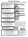
Product Markings
Marquages des Produits / Marcas Puestas en los Productos
MicroLoc™
MILLER
model 8172
MicroLoc™
MILLER
model 8173
model 8174
UP
HAUT
ALTO
model 8175 Meets OSHA
Meets OSHA
6 ft (1.8m) Max. lanyard length
CE 0333 EN 353-2
UP
HAUT
ALTO
Read, understand and follow all instructions
Failure to do so may result in serious injury or death
Use only 5/8” (16mm) Dia. or 3/4” (19mm) Dia.
synthetic rope
Maximum capacity 310 lbs (141 Kg)
Made in France
MILLER
Meets OSHA
3 ft (0.9 m) Max. lanyard length
Use only with locking carabiner
CE 0333 EN 353-2
UP
HAUT
ALTO
Read, understand and follow all instructions
Failure to do so may result in serious injury or death
Use only 5/8” (16mm) Dia synthetic rope
Maximum capacity 310 lbs (141 Kg)
Instructions en Franqais sont a l’interieur
MILLER
Meets OSHA
3 ft (0.9 m) Max. lanyard length
Use only with locking carabiner
UP
HAUT
ALTO
Read, understand and follow all instructions
Failure to do so may result in serious injury or death
Use only 5/16” (8.3mm) Dia wire rope
Maximum capacity 310 lbs (141 Kg)
Instructions en Franqais sont a l’interieur
Use only 5/8 in. (16mm) dia. synthetic rope
Max. 3ft (0.9m) lanyard
Read and follow instructions!
Made in France
MILLER Model/Modele 8174
Read and follow all instructions before use.
Lisez et suivez toutes les instructions avant utilisation.
Never use with incompatible lifelines.
Use only 5/8” (16mm) dia. synthetic rope.
Utilisation seulement 5/8” (16mm) dia. Corde synthétique.
Maximum capacity 310 lbs. (141 Kg)
Made in France
127$&HVPDUTXDJHVYLVHQWOHPRGqOH
8174C ( vendu au Canada ) et le modèle
=YHQGXDX[e8
127$(VWDVPDUFDVFRUUHVSRQGHQDO
PRGHOR&VHYHQGHHQ&DQDGi\DO
PRGHOR=VHYHQGHHQ((88
MILLER Model/Modele 8175
0HHWV26+$$16,=$-DQG&6$=-98 ADP
IWP0D[ODQ\DUGOHQJWK
Read and follow all instructions before use.
Lisez et suivez toutes les instructions avant utilisation.
Never use with incompatible lifelines.
Use only 5/8” (16mm) dia. synthetic rope.
Utilisation seulement 5/8” (16mm) dia. Corde synthétique.
Maximum capacity 310 lbs. (141 Kg)
Made in France
25
UP
HAUT
ALTO
UP
HAUT
ALTO
Meets OSHA, ANSI Z359.1, A10.32-2004
and CSA Z259.2.1-98 MDP
6 ft. (1.8m) Max. lanyard length
127(7KHVHPDUNLQJVSHUWDLQWR0RGHO
&VROGLQ&DQDGDDQG0RGHO=
(sold in U.S.).
127(7KHVHPDUNLQJVSHUWDLQ
to Model 8175C (sold in Canada)
DQG0RGHO=VROGLQ86
127$&HVPDUTXDJHVYLVHQW
le modèle 8175C ( vendu au
&DQDGDHWOHPRGqOH=
YHQGXDX[e8
127$(VWDVPDUFDVFRUUHVSRQden al modelo 8175C (se vende
HQ&DQDGi\DOPRGHOR=
VHYHQGHHQ((88
Inspection and Maintenance Log
Registre D'inspection et D'entretien
Registro de Inspección y Mantenimiento
'$7(2)0$18)$&785(_________________________________________________
'$7('()$%5,&$7,21)(&+$'()$%5,&$&,Ï1
02'(/180%(5________________________________________________________
180e52'(02'Ê/(1Ò0'(02'(/2
'$7(385&+$6('______________________________________________________
'$7('¶$&+$7)(&+$'(&2035$
,163(&7,21'$7(
'$7('¶,163(&7,21
)(&+$'(,163(&&,Ï1
,163(&7,21
,7(06127('
&255(&7,9(
$&7,21
P2,176127e6
/256'(/¶,163(&7,21
P81726'(,163(&&,Ï1
5(/(9$17(6
A&7,21&255(&7,9(
M(','$&255(&7,9$
Approved by:
Approuvé par:
Aprobado por:
Approved by:
Approuvé par:
Aprobado por:
Approved by:
Approuvé par:
Aprobado por:
Approved by:
Approuvé par:
Aprobado por:
Approved by:
Approuvé par:
Aprobado por:
Approved by:
Approuvé par:
Aprobado por:
Approved by:
Approuvé par:
Aprobado por:
Approved by:
Approuvé par:
Aprobado por:
Approved by:
Approuvé par:
Aprobado por:
Approved by:
Approuvé par:
Aprobado por:
26
0$,17(1$1&(
3(5)250('
(175(7,(1())(&78e
M$17(1,0,(172
5($/,=$'2
0,//(5®)$//3527(&7,21352'8&76
727$/6$7,6)$&7,21$6685$1&(
At Miller Fall Protection, we have been providing quality Miller brand fall protection
equipment to millions of workers worldwide since 1945.
/,0,7('/,)(7,0(:$55$17<
BACKED BY OVER 60 YEARS IN THE FALL PROTECTION BUSINESS
We sincerely believe that our fall protection equipment is the best in the world.
Our products endure rigorous tests to ensure that the fall protection equipment you trust is manufactured
to the highest standards. Miller fall protection products are tested to withstand normal wear and tear,
but are not indestructible and can be damaged by misuse.
Our Limited Lifetime Warranty does not apply to normal wear and tear or abusive treatment of the product.
In the unlikely event that you should discover defects in either workmanship or materials,
under our Limited Lifetime Warranty, we will repair or replace the product at our expense.
If a replacement is necessary and your product is no longer available, a comparable product will be substituted.
Should a product issue surface, contact us at 800.873.5242.
0DQXIDFWXULQJVSHFL¿FDWLRQVDUHVXEMHFWWRFKDQJHZLWKRXWQRWLFH
352'8,760,//(5®)$//3527(&7,21
$6685$1&('(6$7,6)$&7,21727$/(
Chez Miller Fall Protection, nous fournissons des équipements de protection contre les chutes de marque
Miller de qualité à des millions de travailleurs dans le monde entier depuis 1945.
*$5$17,(/,0,7e(¬9,(
ASSURÉE GRÂCE À PLUS DE 60 ANS PASSÉS DANS LE DOMAINE DE LA PROTECTION CONTRE LES CHUTES
Nous croyons sincèrement que notre équipement de protection contre les chutes est le meilleur au monde. Nos
SURGXLWVVRQWVRXPLVjGHVWHVWVULJRXUHX[D¿QG¶DVVXUHUTXHOHVpTXLSHPHQWVGHSURWHFWLRQFRQWUH
OHVFKXWHVGDQVOHVTXHOVYRXVDYH]FRQ¿DQFHVRQWIDEULTXpVVHORQOHVQRUPHVOHVSOXVH[LJHDQWHV
/HVSURGXLWVGHSURWHFWLRQFRQWUHOHVFKXWHV0LOOHUVRQWVRXPLVjGHVHVVDLVSRXUYpUL¿HUTX¶LOVUpVLVWHQWjXQHXVXUH
normale; ils ne sont cependant pas indestructibles et peuvent s’endommager en cas de mauvaise utilisation. Notre
garantie limitée à vie ne s’applique pas à l’usure normale ou à un usage abusif du produit.
Dans le cas peu probable où vous découvririez des défauts, soit de fabrication, soit de matériau,
dans le cadre de notre garantie à vie, nous réparerons ou remplacerons le produit à nos frais.
En cas de remplacement, si votre produit n’est plus offert, vous recevrez un produit comparable.
En cas de problème sur un produit, nous contacter au 800-873-5242.
/HVFDUDFWpULVWLTXHVGHIDEULFDWLRQSHXYHQWrWUHPRGL¿pHVVDQVSUpDYLV
352'8&726$17,&$Ë'$60,//(5®
*$5$17Ë$'(6$7,6)$&&,Ï1727$/
En Miller Fall Protection, venimos suministrando desde 1945 los equipos de protección anticaídas
con la calidad Miller a millones de trabajadores en todo el mundo.
*$5$17Ë$/,0,7$'$'(3259,'$
NOS RESPALDAN MÁS DE 60 AÑOS EN LA FABRICACIÓN DE EQUIPO ANTICAÍDAS
Sinceramente creemos que su equipo de protección contra caídas es el mejor del mundo. Nuestros productos resisten
rigurosas pruebas para garantizar que el equipo de protección contra caídas en el que usted confía está fabricado de
conformidad con las normas más elevadas. Los productos anticaídas Miller son sometidos a pruebas para que resistan el
desgaste normal, pero no son indestructibles y su incorrecta utilización puede dañarlos.
Nuestra Garantía limitada de por vida no se aplica al desgaste normal ni al maltrato del producto.
En el poco probable caso de que usted descubriera defectos de mano de obra o materiales, por nuestra Garantía limitada de por vida, repararemos o sustituiremos el producto por cuenta nuestra. Si un reemplazo es necesario y nuestro
producto ya no está disponible, se lo sustituiremos por otro comparable.
En caso de que surja un problema con el producto, contáctenos al 800.873.5242.
/DVHVSHFL¿FDFLRQHVGHIDEULFDFLyQHVWiQVXMHWDVDPRGL¿FDFLRQHVVLQSUHYLRDYLVR
27
Toll Free: 800.873.5242
Fax: 800.892.4078
Download this manual at: www.millerfallprotection.com
Téléchargez ce manuel à l’adresse: www.millerfallprotection.com
Puede bajar por Internet este manual en: www.millerfallprotection.com
Honeywell Safety Products
P.O. Box 271, 1345 15th Street
Franklin, PA 16323 USA