1
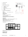
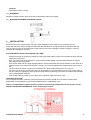
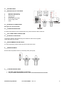
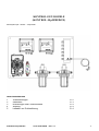
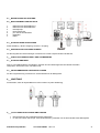
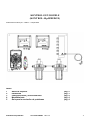
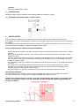
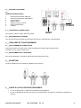
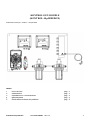
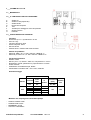
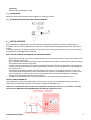
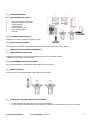
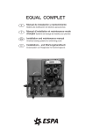
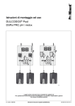
KONTROL GEN DOUBLE (KONTROL 40 pH/REDOX) 0000136989 rev. 1.0 INSTRUCTIONS MANUAL EN HANDBUCH DE MANUAL DE INSTALACION ES MANUEL D’INSTALLATION FR MANUALE D’INSTALLAZIONE IT MANUAL DE INSTALAÇÃO PT KONTROL GEN DOUBLE (KONTROL 40 pH/REDOX) pH measurement system – Redox - Temperature CONTENTS 1 2 3 4 5 First of all Installation Settings and Operation Maintenance Troubleshooting KONTROL 40 pH/Redox Cod. 0000136989 page 2 page 3 page 4 page 4 page 4 rev. 1.0 1 1___FIRST OF ALL 1.1__WELCOME 1.2__THE PACKAGE CONTENTS A B C D E F G H pH probe PT100 probe (Optional) Redox probe Buffer solution kit Pipes Plugs for fixing the panel to the wall Filter key Panel 1.3__TECHNICAL CHARACTERISTICS - Panel Dimensions: (H x L x S) 420x 630 x 10 mm Weight: 6.7 kg Sample inlet: 8X12 Sample outlet: 8X12 Flow sensor Flow alarm: Reed contact flow absence - Measuring the pH/Redox Electrode: SRH-1-S-1,5 –999..+999 mV 3 BAR 60 °C pH electrode: SRH-1-S-1,5 -999..+999 mV 3 BAR 60 °C - Electronic tool Model: PR40 Measurements: pH 014, Redox ± 1500 mV, Temperature 0100°C Regulations: On/Off, break/work, proportional signal Outputs: relay/mA Calibration: self-calibrating pH, Redox Power supply: standard 100240 ± 10%, 50/60 Hz Dosing system PVDF Model 603 Pressure Flow: cc /stroke. bar L/h 12 4 0.42 10 8 5 6 0.52 2 8 0.83 Connections (mm) Strokes / min Int / Ext 0.63 4/6 160 Materials that make up the pump head - PUMP BODY: PVDF CONNECTORS: PVDF MEMBRANE: PTFE VALVES: CERAMIC KONTROL 40 pH/Redox Cod. 0000136989 rev. 1.0 2 - Optional Temperature sensor: PT100 1.4__WARNINGS Keep the hydraulic section clean where the pH and Redox probes are located. 1.5__MATERIAL REQUIRED FOR INSTALLATION 2___INSTALLATION Disconnect the power supply before carrying out the installation of the system or any maintenance on it. Check that the power supply voltage coincides with that indicated on the tag placed on the measurement tool. Lack of respect for any of the instructions in this manual could cause damage to people or things or incorrect operation and damage to the parts. FOR THE INSTALLATION, PROCEED AS FOLLOWS: - - - Position the panel on the wall at a height from the ground that makes it easy to access both the lower and the upper part of the panel. Note The panel must be positioned on a level and if possible straight. Leave the floor area free in order to allow easy access to the panel. Connect the water inlet to a tap that guarantees an uninterrupted water flow rate of between 40 and 60 l/h at a pressure equal to the outlet back pressure + 0.5 bar; it is recommended that this pressure does not exceed 6 bar. The flow rate must remain constant; any variations can cause measurement errors of 1.5%/ l/h. For lack of power supply, the delivery hose can be emptied; it is recommended to insert a non-return valve at the inlet. Hence, the emptying of the electrode-holder tank by siphoning is prevented, a situation that damages the pH measurement electrode. Connect the outlet to a water recovery point with a maximum back pressure of 5 bar. TANK INSTALLATION Do not position the tanks containing chemical substances under the CLOR TOP; the fumes emitted cause deterioration of the equipment. The recommended distance is a MINIMUM of 2 m. NOTE: For calibrating the probes and the connection of the dosing pumps and their use, please see the INSTALLER INSTRUCTION MANUAL of the measurement system. KONTROL 40 pH/Redox Cod. 0000136989 rev. 1.0 3 2.1__SYSTEM FIXING 2.2__DESCRIPTION OF THE PARTS 1 2 3 4 5 6 7 Electronic tool PR40 pH Electronic tool PR40 Rx Dosing pump Flow sensor pH and Rx probe holder Power supply cable Panel OUTLET 2.3__HYDRAULIC CONNECTIONS See figure for inlet and outlet INLET 2.4__ALARM INTERVENTIONS For alarm interventions on the measurement tool, please read the relative manuals. 3___SETTINGS AND OPERATION 3.1__HYDRAULIC OPERATION Connect the delivery and the discharge and set 60 l/h with the flow regulator, check that there are no leaks. 3.2__PROGRAMMING AND SETTINGS For the programming, please read about the measurement tools. 4___MAINTENANCE Ensure that the hydraulic section is constantly clean (see figure). 5___TROUBLESHOOTING For leaks, check the hydraulic connections. For pH or Redox measurement errors, refer to the measurement tool manual. KONTROL 40 pH/Redox Cod. 0000136989 rev. 1.0 4 KONTROL GEN DOUBLE (KONTROL 40 pH/REDOX) Messsystem pH – Redox – Temperatur INHALTSVERZEICHNIS 1 2 3 4 5 Vorbemerkungen Installation Einstellungen und Funktionsweise Wartung Leitfaden zur Problemlösung KONTROL 40 pH/Redox Code 0000136989 S. 2 S. 3 S. 4 S. 4 S. 4 Rev. 1.0 1 1___VORBEMERKUNGEN 1.1__WILLKOMMEN 1.2__VERPACKUNGSINHALT A B C D E F G H pH-Sonde Sonde PT100 (Extrazubehör) Redox-Sonde Kit Pufferlösung Rohre Dübel zur Befestigung der Platte an der Wand Filterschlüssel Platte 1.3__TECHNISCHE EIGENSCHAFTEN - Platte Abmessungen: (H x B x T) 420 x 630 x 10 mm Gewicht: 6,7 Kg Eingang Probe: 8X12 Ausgang Probe: 8X12 Durchflusssensor Durchflussalarm: Reedkontakt fehlender Durchfluss - Messung ph/Redox Elektrode: SRH-1-S-1,5 –999..+999 mV 3 BAR 60°C pH-Elektrode: SRH-1-S-1,5 -999..+999 mV 3 BAR 60°C - Elektronisches Gerät Modell: PR40 Messungen: pH 0-14, Redox ± 1500 mV, Temperatur 0-100°C Einstellungen: An/Aus, Unterbrechung/Betrieb, Strom-Proportionalregelung Ausgänge: Relais/mA Kalibrierung: selbstkalibrierend pH, Redox Stromversorgung: Standard 100-240 ± 10%, 50/60 Hz Dosiersystem PVDF Modell 603 Druck Förderleistung cc /Impulse bar l/h 12 4 0,42 10 8 5 6 0,52 2 8 0,83 Anschlüsse (mm) Impulse / min IN / OUT 0,63 4/6 160 Materialien, aus denen der Pumpenkopf aufgebaut ist - PUMPENKÖRPER: PVDF ANSCHLÜSSE: PVDF MEMBRAN: PTFE VENTILE: KERAMIK KONTROL 40 pH/Redox Cod. 0000136989 rev. 1.0 2 - Extrazubehör Temperatursensor: PT100 1.4__WARNHINWEISE Den Hydraulikbereich, in dem die pH- und Redox-Sonden untergebracht sind, sauber halten. 1.5__NOTWENDIGES INSTALLATIONSMATERIAL 2___INSTALLATION Vor der Installation oder Wartung des Systems die Netzspannung abschalten. Die Netzspannung überprüfen und sicherstellen, dass diese mit der angegebenen Spannung auf dem Schild des Messgeräts übereinstimmt. Die Nichtbeachtung der hier aufgeführten Vorschriften kann zu Sach- oder Personenschäden führen, Teile des Systems beschädigen oder deren Funktion beeinträchtigen. FÜR DIE INSTALLATION WIE FOLGT VORGEHEN: - - - Die Platte so hoch vom Boden an der Wand positionieren, dass ein leichter Zugang sowohl zum Unterteil, als auch zum Oberteil der Platte gewährleistet wird. ANM.: Die Platte muss unter Zuhilfenahme einer Wasserwaage und nach Möglichkeit lotrecht positioniert werden. Den Fußboden frei halten, um einen leichten Zugang zur Platte zu gewährleisten. Den Wassereingang an der Wasserzufuhr anschließen, und dabei beachten, dass ein ununterbrochener Durchfluss zwischen 40 und 60 l/h und ein Druck entsprechend des Gegendrucks des Ausgangs (+ 0,5 bar) gewährleistet ist. Dieser Druck sollte nicht über 6 bar liegen. Der Durchfluss muss konstant bleiben. Etwaige Veränderungen haben einen Messfehler in Höhe von 1,5%/ l/h zur Folge. Soweit der Druckschlauch bei fehlender Stromversorgung geleert werden kann, sollte am Eingang ein Rückschlagventil eingesetzt werden. Auf diese Weise wird die Entleerung des Elektrodenhalterungsbehälters durch Syphonierung verhindert, was zu einer Beschädigung der pH-Messelektrode führen würde. Den Ausgang an einen Wasserrücklauf mit Gegendruck von max. 5 bar anschließen. INSTALLATION DER TANKS Keine Kanister mit Chemikalien unter dem CLOR TOP positionieren. Die austretenden Dämpfe beschädigen die Geräte. Der empfohlene Abstand liegt bei MINDESTENS 2 m. ANMERKUNGEN: Für die Kalibrierung der Sonden und den Anschluss der Dosierpumpen und deren Gebrauch verweisen wir auf das MONTAGEHANDBUCH des Messsystems. KONTROL 40 pH/Redox Cod. 0000136989 rev. 1.0 3 2.1__BEFESTIGUNG DES SYSTEMS 2.2__BESCHREIBUNG DER BAUTEILE 1 2 3 4 5 6 7 Elektronisches Gerät PR40 pH Elektronisches Gerät PR40 Rx Dosierpumpe Durchflusssensor pH- und Rx-Sondenhalter Netzkabel Platte OUTLET 2.3__HYDRAULISCHE ANSCHLÜSSE Siehe Abbildung, INLET= Eingang, OUTLET= Ausgang INLET 2.4__EINGRIFFE BEI FEHLERMELDUNGEN Für die Eingriffe bei Fehlermeldungen verweisen wir auf die entsprechenden Handbücher. 3___EINSTELLUNGEN UND FUNKTIONSWEISE 3.1__HYDRAULIKBETRIEB Den Zu- und Ablaufschlauch anschließen und über den Durchflussregler 60 Liter/Stunde einstellen. Überprüfen, dass keine Lecks vorhanden sind. 3.2__PROGRAMMIERUNG UND EINSTELLUNGEN Für die Programmierung verweisen wir auf das Handbuch der Messgeräte. 4___WARTUNG Sicherstellen, dass der Hydraulikbereich immer sauber ist (siehe Abbildung). 5___LEITFADEN ZUR PROBLEMLÖSUNG Bei Wasserlecks die Hydraulikanschlüsse überprüfen. Im Fall von Fehlern bei der pH- oder Redox-Messung verweisen wir auf das Handbuch des Messgeräts. KONTROL 40 pH/Redox Cod. 0000136989 rev. 1.0 4 KONTROL GEN DOUBLE (KONTROL 40 pH/REDOX) Sistema de medición pH – Redox – Temperatura ÍNDICE 1 2 3 4 5 Antes de empezar Instalación Configuraciones y funcionamiento Mantenimiento Guía para la resolución de problemas KONTROL 40 pH/Redox Cód. 0000136989 pág. 2 pág. 3 pág. 4 pág. 4 pág. 4 rev. 1.0 1 1___ANTES DE EMPEZAR 1.1__BIENVENIDO 1.2__CONTENIDO DEL EMBALAJE A B C D E F G H Sonda pH Sonda PT100 (Opcional) Sonda Redox Kit soluciones tampón Tubos Tacos para fijar el panel en la pared Llave para filtro Panel 1.3__CARACTERÍSTICAS TÉCNICAS - Panel Dimensiones: (H x A x P) 420 x 630 x 10 mm Peso: 6,7 kg Entrada muestra: 8X12 Salida muestra: 8X12 Sensor de flujo Alarma de flujo: contacto reed ausencia de flujo - Medida del pH/Redox Electrodo: SRH-1-S-1,5 –999..+999 mV 3 BAR 60 °C Electrodo pH: SRH-1-S-1,5 -999..+999 mV 3 BAR 60 °C - Instrumento electrónico Modelo: PR40 Medidas: pH 0414, Redox ± 1500 mV, Temperatura 0100°C Regulaciones: On/Off, pausa/trabajo, proporcional en corriente Salidas: relé/mA Calibración: autocalibrante pH, Redox Alimentación: estándar 100240 ± 10%, 50/60 Hz Sistema de dosificación PVDF Modelo 603 Conexiones Presión Caudal bar L/h 12 4 0,42 10 8 5 6 0,52 2 8 0,83 cc /golpe Altura (mm) Golpes / min Entrada/Salida 0,63 4/6 160 Materiales que componen la cabeza de la bomba - CUERPO BOMBA: PVDF CONECTORES: PVDF MEMBRANA: PTFE VÁLVULAS: CERÁMICA KONTROL 40 pH/Redox Cód. 0000136989 rev. 1.0 2 - Opcional Sensor de la temperatura: PT100 1.4__ADVERTENCIAS Mantener limpia la sección hidráulica donde están alojadas las sondas pH y Redox. 1.5__MATERIAL NECESARIO PÁRA LA INSTALACIÓN 2___INSTALACIÓN Antes de efectuar la instalación o el mantenimiento del sistema, desconectar la alimentación de tensión. Comprobar que la tensión de alimentación coincida con la indicada en la placa que se encuentra en el instrumento de medición. La inobservancia de las presentes prescripciones puede provocar daños a las personas y las cosas, así como un mal funcionamiento del aparato o el deterioro de alguna de sus partes. PARA LA INSTALACIÓN, SEGUIR ESTE PROCEDIMIENTO: - - - Colocar el panel en la pared a una altura del suelo que permita acceder fácilmente a la parte inferior y superior del panel. N.B. el panel debe quedar nivelado y, si es posible, a plomo. Dejar libre el pavimento para poder acceder fácilmente al panel. Conectar la entrada del agua a una toma que garantice ininterrumpidamente un caudal de agua comprendido entre 40 y 60 l/h a una presión equivalente a la contrapresión de salida + 0,5 bar. Es aconsejable que dicha presión no supere los 6 bar. El caudal debe permanecer constante. Sus posibles variaciones provocan un error en la medida equivalente a 1,5%/ l/h. Si en ausencia de alimentación puede vaciarse el tubo de envío, es aconsejable introducir una válvula antirretorno en la entrada. De este modo se evita el vaciado de la cubeta portaelectrodos para sifonaje, situación que daña el electrodo de medición del pH. Conectar la salida a un punto de recuperación del agua con una contrapresión máxima de 5 bar. INSTALACIÓN TANQUES No colocar bidones que contengan sustancias químicas debajo del CLOR TOP: las exhalaciones emitidas provocarían desperfectos en los equipos. La distancia MÍNIMA aconsejada es de 2 m. NOTAS: Para la calibración de las sondas y la conexión de las bombas dosificadoras, y para saber cómo utilizar correctamente el equipo, consulte el MANUAL DE INSTRUCCIONES PARA EL INSTALADOR del sistema de medición. KONTROL 40 pH/Redox Cód. 0000136989 rev. 1.0 3 2.1__FIJACIÓN SISTEMA 2.2__DESCRIPCIÓN DE LAS PARTES 1 2 3 4 5 6 7 Instrumento electrónico PR40 pH Instrumento electrónico PR40 Rx Bomba dosificadora Sensor de flujo Porta sonda pH y Rx Cable de alimentación Panel OUTLET 2.3__CONEXIONES HIDRÁULICAS Véase figura, INLET= Entrada, OUTLET= Salida INLET 2.4__INTERVENCIONES DE ALARMA Para informarse acerca de las intervenciones de alarma del instrumento de medida es aconsejable leer sus respectivos manuales. 3___CONFIGURACIONES Y FUNCIONAMIENTO 3.1__FUNCIONAMIENTO HIDRÁULICO Conectar el envío y la descarga y programar 60 litros/hora con el regulador de flujo; comprobar que no haya pérdidas de agua. 3.2__PROGRAMACIÓN Y CONFIGURACIONES Para efectuar la programación, lea los instrumentos de medida. 4___MANTENIMIENTO Es necesario garantizar una limpieza constante de la sección hidráulica (véase la figura). 5___GUÍA PARA LA RESOLUCIÓN DE PROBLEMAS En caso de que se produzcan pérdidas de agua, controlar las conexiones hidráulicas. En caso de observar errores en la medición del pH o del Redox, tomar como referencia el manual del instrumento de medición. KONTROL 40 pH/Redox Cód. 0000136989 rev. 1.0 4 KONTROL GEN DOUBLE (KONTROL 40 pH/REDOX) Système de mesure pH – Rédox – Température SOMMAIRE 1 2 3 4 5 Opérations préliminaires Installation Réglages et fonctionnement Entretien Guide à la solution des problèmes KONTROL 40 pH/Redox Cod. 0000136989 page page page page page rev. 1.0 2 3 4 4 4 1 1___OPÉRATIONS PRÉLIMINAIRES 1.1__BIENVENUE 1.2__LE CONTENU DE L’EMBALLAGE A B C D E F G H Sonde pH Sonde PT100 (en option) Sonde Rédox Kit solutions tampon Tuyaux Chevilles pour la fixation murale du panneau Clé pour filtre Panneau 1.3__CARACTÉRISTIQUES TECHNIQUES - Panneau Dimensions : (H x L x P) 420x x 630 x 10 mm Poids : 6,7 kg Entrée étalon : 8X12 Sortie étalon : 8X12 Capteur débit Alarme débit : contact à lame absence débit - Mesure du pH/potentiel Rédox Électrode : SRH-1-S-1,5 –999..+999 mV 3 bars 60 °C Électrode pH : SRH-1-S-1,5 -999..+999 mV 3 bars 60 °C - Instrument électronique Modèle : PR40 Mesures : pH 0-14, Rédox ± 1500 mV, Température 0-100°C Réglages : On/Off, arrêt/marche, proportionnel en courant Sorties : relais/mA Étalonnage : étalonnage automatique pH, Rédox Alimentation : standard 100-240 ± 10%, 50/60 Hz Système dosage PVDF Modèle 603 Pression Débit bars 12 10 8 2 l/h 4 5 6 8 cm³/coup Connections coups/min (mm) Int. / Ext. 0,42 0,52 0,63 0,83 4/6 160 Matériaux qui constituent la tête de la pompe - - CORPS POMPE : PVDF CONNECTEURS : PVDF MEMBRANE : PTFE VANNES : CÉRAMIQUE En option Capteur de la température : PT100 KONTROL 40 pH/Redox Réf. 0000136989 rév. 1.0 2 1.4__AVERTISSEMENTS Maintenir propre la section hydraulique où les sondes pH et Rédox sont logées. 1.5__MATÉRIEL NÉCESSAIRE POUR L’INSTALLATION 2___INSTALLATION Avant de procéder à l’installation ou à l’entretien du système, couper l’alimentation électrique. Contrôler que la tension d’alimentation correspond à la tension indiquée sur la plaquette située sur l’instrument de mesure. L’inobservance des prescriptions contenues dans ce manuel peut provoquer des dommages aux personnes et aux choses ou le fonctionnement incorrect et l’endommagement des pièces. PROCÉDURE D’INSTALLATION : - - - positionner le panneau sur le mur à une hauteur du sol qui rende facilement accessible aussi bien sa partie inférieure que sa partie supérieure. N.b. : le panneau doit être mis de niveau et, si possible, d’aplomb. Laisser le sol libre afin de faciliter l’accès au panneau. Raccorder l’entrée de l’eau à une prise qui assure sans interruptions un débit d’eau compris entre 40 et 60 l/h, avec une pression égale à la contre-pression de sortie + 0,5 bar. Il est préférable que cette pression ne dépasse pas 6 bars. Le débit doit rester constant, les éventuelles variations comportent une erreur sur la mesure égale à 1,5%/ l/h. Si le tuyau d’aspiration peut se vider en cas d’absence d’alimentation en eau, il est conseillé d’insérer un clapet anti-retour sur l’entrée, De cette façon, on évite le vidage du bac porte-électrodes par siphonnage, ce qui endommagerait l’électrode de mesure du pH. Raccorder la sortie à un point de récupération de l’eau avec une contre-pression maximum de 5 bars. INSTALLATION DES RÉSERVOIRS Ne pas positionner les bidons contenant des substances chimiques sous le CLOR TOP car les exhalations émises provoquent la détérioration des appareils. La distance MINIMUM conseillée est de 2 m. REMARQUE : Pour l’étalonnage des sondes et le raccordement des pompes doseuses et leur utilisation, se référer au MANUEL D’INSTRUCTIONS POUR L’INSTALLATEUR du système de mesure. KONTROL 40 pH/Redox Réf. 0000136989 rév. 1.0 3 2.1__FIXATION DU SYSTÈME 2.2__ DESCRIPTION DES PIÈCES 1 2 3 4 5 6 7 Instrument électronique PR40 pH Instrument électronique PR40 Rédox Pompe doseuse Capteur débit Supports sondes pH et Rx Cordon d’alimentation Panneau OUTLET 2.3__CONNEXIONS HYDRAULIQUES INLET Voir la figure : INLET= Entrée, OUTLET= Sortie 2.4__INTERVENTIONS D’ALARME Pour les interventions d’alarme de l’instrument de mesure, lire les Manuels correspondants. 3___RÉGLAGES ET FONCTIONNEMENT 3.1__FONCTIONNEMENT HYDRAULIQUE Raccorder l’arrivée et la sortie, puis, à l’aide du régulateur de débit, régler 60 litres/heure. Contrôler qu’il n’y a pas de fuites d’eau. 3.2__PROGRAMMATION ET RÉGLAGES Pour la programmation, consulter le manuel des instruments de mesure. 4___ENTRETIEN Toujours maintenir propre la section hydraulique (voir la figure). 5___GUIDE À LA SOLUTION DES PROBLÈMES En cas de fuites d’eau, contrôler les raccordements hydrauliques. En cas de problèmes de mesure du pH ou du potentiel Rédox, se référer au manuel de l’instrument de mesure. KONTROL 40 pH/Redox Réf. 0000136989 rév. 1.0 4 KONTROL GEN DOUBLE (KONTROL 40 pH/REDOX) Sistema di misura pH – Redox – Temperatura INDICE 1 2 3 4 5 Prima di tutto Installazione Impostazioni e funzionamento Manutenzione Guida alla soluzione dei problemi KONTROL 40 pH/Redox Cod. 0000136989 pag pag pag pag pag rev. 1.0 2 3 4 4 4 1 1___PRIMA DI TUTTO 1.1__BENVENUTO 1.2__IL CONTENUTO NELLA CONFEZIONE A B C D E F G H Sonda pH Sonda PT100 (Opzionale) Sonda Redox Kit soluzioni tampone Tubi Tasselli per il fissaggio al muro del pannello Chiave per filtro Pannello 1.3__CARATTERISTICHE TECNICHE - Pannello Dimensioni:(H x L x S) 420x 630 x 10 mm Peso: 6.7 Kgr Ingresso campione: 8X12 Uscita campione: 8X12 Sensore flusso Allarme flusso: contatto reed assenza flusso - Misura del pH/Redox Elettrodo: SRH-1-S-1,5 –999..+999 mV 3 BAR 60 °C Elettrodo pH: SRH-1-S-1,5 -999..+999 mV 3 BAR 60 °C - Strumento elettronico Modello: PR40 Misure: pH 014, Redox ± 1500 mV, Temperatura 0100°C Regolazioni: On/Off, pausa/lavoro, proporzionale in corrente Uscite: relè/mA Calibrazione: autocalibrante pH, Redox Alimentazione: standard 100240 ± 10%, 50/60 Hz Sistema dosaggio PVDF Model 603 Pressure Flow Rate cc /stroke. bar L/h 12 4 0,42 10 8 5 6 0,52 2 8 0,83 Connections (mm) Strokes / min Int / Ext 0,63 4/6 160 Materiali che compongono la testa della pompa - CORPO POMPA: PVDF CONNETTORI: PVDF MEMBRANA: PTFE VALVOLE: CERAMICA KONTROL 40 pH/Redox Cod. 0000136989 rev. 1.0 2 - Opzionale Sensore della temperatura: PT100 1.4__AVVERTENZE Mantenere pulito il setto idraulico dove alloggiano le sonde pH e Redox. 1.5__MATERIALE NECESSARIO PER L’INSTALLAZIONE 2___INSTALLAZIONE Prima di effettuare l’installazione o la manutenzione del sistema disconnettere la tensione di alimentazione. Controllare che la tensione di alimentazione coincida con quella indicata sulla targhetta posta sullo strumento di misura. Il mancato rispetto di una della prescrizioni qui contenute può provocare danni a persone e cose o il non corretto funzionamento e danneggiamento delle parti. PER L’INSTALLAZIONE PROCEDERE NEL SEGUENTE MODO: - - - Posizionare il pannello a muro ad una altezza da terra che renda di facile accesso, sia la parte inferiore che la parte superiore del pannello. N.B. Il pannello deve essere posizionato in bolla e possibilmente a piombo. Lasciare libero il pavimento al fine di rendere comodo l’accesso al pannello. Collegare l’ingresso dell’acqua ad una presa che garantisca ininterrottamente una portata d’acqua compresa tra 40 e 60 l/h ad una pressione pari alla contropressione d’uscita + 0,5 bar, tale pressione è consigliabile che non superi i 6 bar. La portata deve rimanere costante, eventuali variazioni provocano un errore sulla misura pari a 1,5%/ l/h. Se in mancanza di alimentazione il tubo di mandata si può svuotare è consigliabile inserire una valvola di non ritorno all’ingresso. In questo modo si evita lo svuotamento della vaschetta portaelettrodi per sifonaggio, situazione che danneggia l’elettrodo di misura del pH. Collegare l’uscita ad un punto di recupero dell’acqua con una contropressione massima di 5 bar. INSTALLAZIONE SERBATOI Non posizionare i bidoni contenenti sostanze chimiche sotto il CLOR TOP le esalazioni emesse provocano un deterioramento delle apparecchiature. La distanza consigliata è di MINIMO 2 mt. NOTE: Per la calibrazione delle sonde ed il collegamento delle pompe dosatrici e loro utilizzo si rimanda alla lettura del MANUALE ISTRUZIONI INSTALLATORE del sistema di misura. KONTROL 40 pH/Redox Cod. 0000136989 rev. 1.0 3 2.1__FISSAGGIO SISTEMA 2.2__DESCRIZIONE DELLE PARTI 1 2 3 4 5 6 7 Strumento elettronico PR40 pH Strumento elettronico PR40 Rx Pompa dosatrice Sensore flusso Porta sonda pH e Rx Cavo di alimentazione Pannello OUTLET 2.3__CONNESSIONI IDRAULICHE Vedere figura, INLET= Ingresso, OUTLET= Uscita INLET 2.4__INTERVENTI DI ALLARME Per gli interventi di allarme dello strumento di misura si rimanda alla lettura dei relativi Manuali. 3___IMPOSTAZIONI E FUNZIONAMENTO 3.1__FUNZIONAMENTO IDRAULICO Collegare la mandata e lo scarico ed impostare 60 litri/ora con il regolatore di flusso, verificare che non ci siano perdite d’acqua. 3.2__PROGRAMMAZIONE E IMPOSTAZIONI Per la programmazione si rimanda alla lettura degli strumenti di misura. 4___MANUTEZIONE Assicurare una costante pulizia della sezione idraulica (vedi figura). 5___GUIDA ALLA SOLUZIONE DEI PROBLEMI In caso di perdite d’acqua verificare le connessioni idrauliche. In caso di errori nella misura del pH o del Redox, fare riferimento al manuale dello strumento di misura. KONTROL 40 pH/Redox Cod. 0000136989 rev. 1.0 4