1
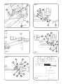
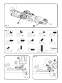
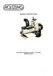
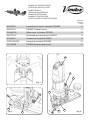
MANUAL DE INSTRUCCIONES
OPERATING INSTRUCTIONS
MODE D'EMPLOI
GEBRAUCHSANWEISUNG
MANUALE D'ISTRUZIONI
MANUAL DE INSTRUÇÕES
ИНСТРУКЦИЯ ПО ЭКСПЛУАТАЦИИ
página/page
seite/pagina
страница
ESPAÑOL
Fresadora de cantos inclinable FR292R
6
ENGLISH
FR292R Tiltable trimmer
FRANÇAIS
Affleureuse inclinable FR292R
12
DEUTSCH
Schwenkbare Kantenfräse FR292R
15
ITALIANO
Fresatrice inclinabile FR292R
18
PORTUGUÉS
Fresadora inclinável FR292R
22
РУССКИЙ
FR292R Фрезер кромочный
25
9
A1
A
D
Fig. 1
H
B
O
H
Fig. 3
2
X
M
M1
H
Fig. 2
Fig. 4
H
Fig. 5
C
E
A
D
Y
E
B
L
H
K
W
A
Y
G1
D
B
H
E
M
N
F
Fig. 6
Fig. 7
M1
Fig. 8
B
D
Y
N
A
M
H
F
M1
Fig. 9
3
N
Fig. 10
R
Fig. 11
a1
b1
a2
b2
c
d
e
f
f1
g1
g2
h
i
j
Fig. 13
Fig. 12
4
k
Fig. 15
Fig. 14
H
B3
Fig. 16
T
V
R
S
Fig. 17
Q
Fig. 18
5
incluida de origen.
Fresas par aplicaciones varias: Ver página 29
6446073 Acoplamiento de aspiración
¡ATENCIÓN! Utilizar siempre fresas con el diámetro
de la caña adecuado a la pinza que va a utilizar y
adaptadas a la velocidad de la màquina.
12. NIVEL DE RUIDO Y VIBRACIONES
Las mediciones de esta herramienta eléctrica han sido
efectuadas según Norma Europea EN50144.
El nivel de ruidos en el puesto de trabajo puede sobrepasar 85 dB(A). En este caso es necesario tomar
medidas de protección contra el ruido para el usuario
de la herramienta.
13. GARANTÍA
Todas las máquinas electroportátiles VIRUTEX tienen
una garantía válida de 12 meses a partir del día de su
suministro, quedando excluidas todas las manipulaciones o daños ocasionados por manejos inadecuados
o por desgaste natural de la máquina.
Para cualquier reparación dirigirse al servicio oficial
de asistencia técnica VIRUTEX.
VIRUTEX se reserva el derecho de modificar sus
productos sin previo aviso.
English
FR292R TILTABLE TRIMMER
IMPORTANT
CAUTION. Read these OPERATING INSTRUCTIONS
and the attached GENERAL SAFETY INSTRUCTIONS
LEAFLET carefully before using the machine. Make
sure you have understood them before operating the
machine for the first time.
Keep both sets of instructions for any future queries.
1. SAFETY INSTRUCTIONS
FOR USING THE ROUTER
1.WARNING! Carefully read the GENERAL SAFETY
INSTRUCTION LEAFLET enclosed with the machine
documents.
2. Before plugging in the machine, make sure that the
power supply voltage is the same as that shown on
the specifications plate.
3. Always keep your hands away from the cutting area.
Always grip the machine safely.
4. Use protective goggles.
5. Always use original VIRUTEX tools. Never use
defective or damaged tools.
6. Always use cutter bits with the appropriate stem
diameter for the chuck collet and tool speed to be
used.
7. WARNING! Unplug the machine from the power
supply before performing any maintenance opera-
tions.
2. SPECIFICATIONS
Power..............................................................750 W
Universal motor..............................………..50/60 Hz
Revolutions..............................14,000 – 30,000/min
Ø max bit...........................................………..25 mm
Ø standard chuck collet........................…….6 and 8 mm
Weighted equivalent acoustic,
continuous pressure level...............................83 dB(A)
Acoustic pressure level..............................98 dB(A)
Usual vibration level (hand-arm)....................<2.5 m/s2
Weight..................................................……...2.2 Kg
3. STANDARD EQUIPMENT
Inside the carrying case the following items will be
found:
• FR292R Router with 8- and 6-mm chucks.
• Straight cutter for trimming and slotting D.18 LC.
20
• Key: 11 mm for motor shaft.
• Key: 19 mm for chuck collet attachment.
• Copying device
• Lateral square with centring shaft
• 3-mm Allen wrench
• Operating instructions and other documents
4. GENERAL DESCRIPTION OF THE ROUTER
The FR292R router can be used for trimming laminates,
shaping small mouldings, rabbeting, making straight
cut-outs, chamfering, etc. Its head may be tilted from
0 to 91.5° to cut bevelled edges and chamfer using
cylindrical cutters plus many more applications.
It micrometric copying wheel also allows interior curves
with radii over 52 mm to be cut.
It can also cut copies from templates using the copiers
or the template guides shown in section 11 and it
can cut or shape circles using the lateral square and
centring shaft.
5.ASSEMBLY OF THE ROUTER
AND ITS ACCESSORIES
5.1 ASSEMBLING AND CHANGING THE CUTTER
WARNING. Disconnect the machine from the power
supply before assembly.
To change or assemble a cutter in the machine (Fig.
1), block the motor shaft using the key U, unscrew the
nut using the service key Z, take out the used cutter
and attach the new one placing it into the bottom of its
housing and then tighten using the service keys.
WARNING. Check that the stem diameter of the chuck
collet matches that of the cutter stem to be used.
5.2 ASSEMBLING THE COPYING DEVICE
WARNING. Disconnect the machine from the power
supply before assembly.
Place copying device set M (Fig. 2), through holes O
(Fig. 3) on the head and fix it at the required height
using screws H (Fig. 2).
9
5.3 ASSEMBLING THE LATERAL SQUARE
WARNING. Disconnect the machine from the power
supply before assembly.
Place lateral square W (Fig. 5), through holes C (Fig.
4) on the head and fix it at the required height using
screws H.
10) to the on position. To stop the machine, simply
press the back of the switch and it will return to the
off position.
The electronic control enables you to work at the ideal
speed for each type of job and bit. Adjust the speed
using button A1 (Fig. 2).
5.4 ASSEMBLING THE CENTRING DEVICE
Assemble the shaft on the lateral square in the position
shown in (Fig. 6) and fix it with the nut supplied.
8.APPLICATIONS
The many options with the tilting head and the included
accessories give the FR292R a great deal of versatility
to perform such jobs as trimming, slotting, chamfering,
moulding, copying, etc.
6. ADJUSTMENTS
6.1 ADJUSTING HEAD TILT
WARNING. Disconnect the machine from the power
supply before adjustment.
With the FR292R router, head tilt may be set for the
cutter head to be between 0 and 91.5° and may be
locked in any position using screws N (Fig. 7 y 8).
To trim with the 90° conical bit, place the head at 45°
+1° = 46° approximately, to avoid damaging the coating
of the surface when trimming the edge.
Similarly, to trim edges using the D.18 straight bit,
also supplied with the machine, turn the head to the
maximum 91.5°, so that the cutting edge of the bit is
1.5° below the head horizontal (Fig. 9).
6.2 ADJUSTING THE HEAD WITH
REGARD TO THE CUTTER
WARNING. Disconnect the machine from the power
supply before adjustment.
For the cutter head: The head is set at the required
height by loosening knob D (Fig. 7), turning wheel Y
(Fig. 7) until the required position is reached and it is
then fixed there using knob D (Fig. 7).
The head is also supplied with a high-precision micrometric adjustment system on its shaft for making fine
adjustments to cutting depth with screw A (Fig. 7). To
adjust it in this way, loosen knob D (Figs. 7 and 2) and
using screw A slowly turn until the required measurement is obtained. On the side of the machine there is
a reference guide in millimetres G1 (Fig. 7).
For the cutter edge: It also has a fine adjustment system
for the position of the head using screw B (Fig. 7). To
use this adjustment, loosen screw E (Fig. 7) and slowly
turn screw B to the required position.
6.3 AJUSTING THE COPYING SHAFT TO TRIM
WARNING. Disconnect the machine from the power
supply before adjustment.
In order to set the wheel on the copying device at a
suitable distance from the base of the head, loosen
screws H (Fig. 8), raise or lower the copying device to
the required height and fix it again in this position.
To locate the cutter, set the distance to the edge of
the copying device wheel, loosen screw M1(Fig. 8)
and set the position of the wheel using adjustment
nut F (Fig. 8).
7. STARTING
To start the machine, press button R forward (Fig.
10
8.1 TRIMMING SURFACES AND EDGES
WITH THE 90° CONICAL BIT
Trimming the coating of a surface (Fig. 11-a1),
and (Fig. 13):
• First set the head to 46° (Fig. 13), as described in
section 6.1.
• Loosen screw E (Fig. 13), raise the head so it just
reaches the top limit without forcing, by turning knob
B (Fig. 13) clockwise, and fix it in this position.
• Position the base of the head approximately in the
middle of the bit edge by loosening knob D (Fig. 13)
and with the help of control Y and the fine adjustment
knob A (Fig. 13).
• Position feeler M (Fig. 13) so that the bearing is
near the bit and fix it in place using the screws H
(Fig. 13).
• Adjust the position of the bearing, aligning it with the
bit, using nut F (Fig. 13) and fix in place with screw
M1 (Fig. 13).
• If the board is made of particularly coarse fibreboard,
you can use a large support surface lateral square
instead of the bearing feeler. This will prevent irregularities in the board extending to the trim.
• Trim the excess covering from the surface.
Straight edge trimming (Fig. 11-b1) and (Fig. 14):
• Loosen screw E (Fig. 14) and lower the head by turning
knob B (Fig. 14) anti-clockwise, until its base is aligned
with the bit. Then tighten it in the new position. If knob
B (Fig. 14) has been turned as far as it will go and the
bit is still not aligned with the base, do not force the
knob; loosen knob D (Fig. 14) and lower the base of
the head, with knob A (Fig. 14), until aligned.
• Trim the excess edge.
Trimming chamfered edges:
• Chamfered edges may be trimmed to any angle
from 5° to 45°. To do this, loosen the screws N (Fig.
14) and turn the body to the angle marked on the
indicator, i.e. 45°, plus the required chamfer. Then
tighten the screws N.
E.g.: To trim a 30° chamfer, the head must be inclined until the indicator marks 75°, or 90° for a 45°
chamfer.
• Loosen screw E (Fig. 14) and lower the head by
turning knob B (Fig. 14) anti-clockwise, until its base
is approximately in the middle of the bit edge. Then
tighten it in the new position.
• Adjust the position of the feeler bearing, using nut F
(Fig. 13) to obtain the required chamfer depth. Hold
in place with screw M1 (Fig. 13).
• Trim the edge chamfer.
8.2 TRIMMING SURFACES AND EDGES
WITH THE D.18 STRAIGHT BIT
Trimming the coating of a surface (Fig. 11-a2):
First attach the D.18 cylindrical bit, as described in
section 5.1.
Attach the required cutter, using knobs D and Y the
fine adjustment A (Fig. 7).
Set the height of copying device M (Fig. 7), until the
wheel is on the edge and fix this position using nut F
(Fig. 7), so that the cutting edge of the cutter is flush
with the edge of the piece (Fig. 7).
With particularly coarse fibreboard, you can use the
large support surface lateral square instead of the
wheel feeler. This will prevent irregularities in the
board extending to the trimming.
Trim the surface coating of the pannel.
Straight edge trimming (Fig. 11-b2): Place the
motor at 91.5º (Fig. 8), following the instructions in
section 6.1.
Locate the cutting edge on the edge to be trimmed
(Fig. 9). To do so, move the wheel on the copying
device M (Fig. 8) to the edge of a section and then
locate the cutter by moving the motor in the opposite
direction to the wheel, using wheel Y and fine adjustment A (Fig. 8).
Trim the rest of the edge.
8.3 TRIMMING EDGES WITH A SHAPED BIT
Edges can also be trimmed at an angle (Fig. 12) or
chamfered (Fig. 11-c-d), from the vertical or horizontal motor position, if you have the corresponding
profile bit.
8.4 CHAMFERING WITH A STRAIGHT CUTTER
Tilt the motor to 45° or the required angle between 0
and 91.5°, set the copying shaft or lateral square, the
depth and then begin to cut (Fig. 11-f1).
8.5 SLOTTING
Place the lateral square W (Fig. 5) at the required
distance; set the slot depth by turning wheel Y and
fine adjustment A (Fig. 5) then begin to cut (Fig. 11g1-h-i-g2).
8.6 CUTTING COPIES WITH
ANY TEMPLATE (Fig. 11-j)
Copies may be cut from a template by mounting a
copier or template guide L (Fig. 4) suitable for the
cutter to be used. This is held on the base of the head
by screws K (Fig. 4).
Please see the available template guide in section 11
Optional Accessories.
The head must also be place in the appropriate position
for copying with a template. To do so, loosen screw E
(Fig. 4), move the machine’s motor until stop X (Fig.
3), using adjustment screw B (Fig. 3) and tighten
knob E (Fig. 4).
8.7 CUTTING OR TRIMMING CIRCLES
Attach the centring shaft on the lateral square as
described in section 5.4.
Attach the square upside down on the base using
shaft B3 as the centre of the circumference B3 (Fig.
15). Set the size of the required radius and fix it using
screws H (Fig. 15).
9. CONNECTING TO EXTERNAL ASPIRATION
To connect the machine to AS182K, AS282K aspirators or any other external aspiration, the aspiration
connector 6446073 (optional accessory) must be
attached. Connect the rubber nozzle to the machine’s
socket B1 (Fig. 10)
10. BRUSH AND COLLECTOR MAINTENANCE
WARNING. Unplug the machine from the electrical
outlet before carrying out any maintenance.
Remove screws R (Fig. 16) holding the side covers
T and separate them.
Remove the brush-holder S (Fig. 17) with small
screwdriver V, using one of the brush-holder side
tabs to lever it out.
Push back the end of spring Q. Keep it in this position
to extract the brush and replace it with a new genuine
VIRUTEX brush. Reinsert the brush-holder, ensuring
that it is firmly positioned in the casing and that each
of the brushes exerts a small amount of pressure on
the collector.
Reattach the covers "T" with the corresponding
screws, making sure that no wires get caught in the
process.
It is advisable to allow the machine to run for 15 minutes in order to ensure that the brushes have properly
settled into place.
If the collector burns or juts out, it should be serviced
by a Virutex service technician.
Keep the cable and plug in good working condition.
11. ACCESSORIES AND TOOLS
Guides to copy with a template (see Fig. 18)
Reference For cutter size
ØA
ØB
2950104
6 mm
8 mm
10mm
2950105
8 or 7.6
10
12
2950106
10 mm
12
14
2950107
12 mm
14
16
2950081
14 mm
16
18
2950108
16 mm
18
20
1222084 Chuck collet Ø 6 mm.
1222024 Chuck collet Ø 8 mm, supplied.
1222085 Chuck collet Ø 1/4"
1140087 90° trimming bit, supplied.
1140016 Straight bit D.18 mm, supplied.
11
Bits for several jobs: See page 29
6446073 Dust collector connection
WARNING! Always use bits with the appropriate
shank diameter for the chuck collet and tool speed
to be used.
12. NOISE AND VIBRATION LEVEL
The noise and vibration levels of this electrical device
have been measured according to the European
standard EN50144.
The noise level in the workplace can exceed 85 dB(A),
in which case it is necessary for the user to take noise
protection measures.
13. WARRANTY
All VIRUTEX power tools are guaranteed for 12 months
from the date of purchase, excluding any damage which
is a result of incorrect use or of natural wear and tear
on the machine. All repairs should be carried out by the
official VIRUTEX technical assistance service.
VIRUTEX reserves the right to modify its products
without prior notice.
Français
AFFLEUREUSE INCLINABLE FR292R
IMPORTANT
ATTENTION! Avant d'utiliser la machine, lisez attentivement ce MANUEL D'INSTRUCTIONS et la
BROCHURE D'INSTRUCTIONS GÉNÉRALES DE
SÉCURITÉ qui vous sont fournis avec cette machine.
Assurez-vous de bien avoir tout compris avant de
commencer à travailler sur la machine.
Gardez toujours ces deux manuels d'instructions à
portée de la main pour pouvoir les consulter, en cas
de besoin.
1. INSTRUCTIONS DE SÉCURITÉ
POUR LE MANIEMENT DE L'AFFLEUREUSE
1. ATTENTION! Lire attentivement le MANUEL
D’INSTRUCTIONS GÉNÉRALES DE SÉCURITÉ
joint à la documentation de la machine.
2. Avant de brancher la machine, vérifier si la tension
d’alimentation correspond à celle indiquée sur la
plaque de caractéristiques.
3. Toujours maintenir les mains éloignées de la zone
de coupe. Toujours fixer fermement la machine.
4. Utiliser des lunettes de protection.
5. Toujours utiliser des outils d'origine VIRUTEX. Ne jamais utiliser d'outils défectueux ou en mauvais état.
6. Toujours utiliser des fraises au diamètre correct pour
la pince et adaptées à la vitesse de la machine.
7. ATTENTION! Débrancher la machine du secteur
avant de procéder à toute opération de maintenance.
12
2. CARACTÉRISTIQUES
Puissance........................................................750 W
Moteur universel...........................………..50/60 Hz
Tours.....................................14 000 – 30 000/min
Ø fraise max.....................................………..25 mm
Ø pince standard...........................……….6 et 8 mm
Niveau de pression acoustique continu
équivalent pondéré.....................……....…..83 dB (A)
Niveau de puissance acoustique..............98 dB (A)
Niveau de vibrations (main - bras) habituel...<2,5 m/s2
Poids...................................................……......2,2 kg
3. ÉQUIPEMENT STANDARD
La mallette contient les éléments suivants:
• Fraiseuse FR292R avec pince de 8 mm
• Fraise droite pour affleurer et rainurer D.18 LC. 20
• Clef o/c: 11 mm pour arbre moteur.
• Clef o/c: 19 mm pour écrou fixation pince.
• Palpeur
• Équerre latérale avec axe pour centres
• Clef six pans o/c 3 mm
• Manuel d'instructions et documentation variée
4. DESCRIPTION GÉNÉRALE DE LA FRAISEUSE
Les fonctions de la fraiseuse FR292R sont l'affleurage
de stratifiés, la réalisation de petites moulures, de délardements, de rainures droites, de chanfreins, etc. Sa
tête rabattable de 0 à 91,5° permet également de faire
des rainures en biseaux, de réaliser des chanfreins
en utilisant des fraises cylindriques et de multiples
applications additionnelles.
Son palpeur à galet à réglage micrométrique lui permet
aussi de profiler des courbes intérieures d'un rayon
supérieur à 52 mm.
Elle peut également fraiser des copies de gabarit en
utilisant les copieurs ou guides gabarits indiqués au
paragraphe 11 et couper ou profiler des cercles à l’aide
de son équerre latérale et de son axe pour centres.
5.MONTAGE DE LA FRAISE ET
DES ACCESSOIRES
5.1 MONTAGE ET CHANGEMENT DE LA FRAISE
ATTENTION. Débrancher la machine du secteur avant
de procéder à cette opération.
Pour réaliser le changement ou le montage d'une
fraise sur la machine (Fig. 1), bloquer l'arbre moteur,
à l'aide de la clef en U, dévisser l'écrou à l'aide de la
clef de service Z, retirer la fraise utilisée et monter la
nouvelle en l'introduisant au fond de son logement,
la resserrer à l'aide des clefs de service.
ATTENTION. Vérifier si le diamètre de la pince correspond à celui de la tige de la fraise à utiliser.
5.2 MONTAGE DU PALPEUR
ATTENTION. Débrancher la machine du secteur avant
de procéder à cette opération.
Introduire l'ensemble palpeur M (Fig. 2) dans les
orifices O (Fig. 3) de la tête et le fixer à l'aide des vis
H à la hauteur voulue (Fig. 2).