1
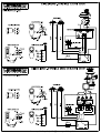
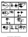
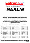
PROJECT X4
INSTRUCTION MANUAL
MANUALE DI ISTRUZIONI
MANUEL D'INSTRUCTIONS
GEBRAUCHSANWEISUNG
MANUAL DE INSTRUCCIÓNES
M.038.04.06 Rev.01
www.busse-yachtshop.de | [email protected]
CONTENTS
Project X4 presentation
Safety information
Windlass wiring minimum requirements
Installation general requirements
Installation procedure
Test procedure
Use of the windlass
Pg.3
Pg.3
Pg.3
Pg.3
Pg.3
Pg.3
Pg.4
Maintenance program
Limited international warranty
Wiring diagram
Pictures
Exploded drawings
Part list
Lofrans sales organization
Pg.5
Pg.5
Pg.18
Pg.19
Pg.20-22
Pg.21-23
Pg.24
Pg.6
Pg.6
Pg.6
Pg.6
Pg.6
Pg.6
Pg.7
Programma di manutenzione
Garanzia internazionale limitata
Schema elettrico
Immagini
Disegni esplosi
Lista parti
Organizzazione di vendita Lofrans
Pg.8
Pg.8
Pg.18
Pg.19
Pg.20-22
Pg.21-23
Pg.24
Pg.9
Pg.9
Pg.9
Pg.9
Pg.9
Pg.9
Pg.10
Programme d'entretien
Garantie internationale limitée
Schéma électrique
Figures
Schéma détaillés
Liste des pièces
Réseau de vente Lofrans
Pg.11
Pg.11
Pg.18
Pg.19
Pg.20-22
Pg.21-23
Pg.24
Pg.12
Pg.12
Pg.12
Pg.12
Pg.12
Pg.12
Pg.13
Wartungsplan
Garantiebedingungen
Elektr. Anschlußplan
Bilder
Explosionszeichnung
Ersatzteilliste
Vertriebsstruktur
Pg.14
Pg.14
Pg.18
Pg.19
Pg.20-22
Pg.21-23
Pg.24
Pg.15
Pg.15
Pg.15
Pg.15
Pg.15
Pg.15
Pg.16
Programa de mantenimiento
Garantìa internacional limitada
Diagrama eléctrico
Figuras
Esquema de piezas
Listas de la piezas
Distribuidores de Lofrans
Pg.16
Pg.17
Pg.18
Pg.19
Pg.20-22
Pg.21-23
Pg.24
SOMMARIO
Presentazione del Project X4
Informazioni sulla sicurezza
Requisiti minimi dell’impianto elettrico
Requisiti generali per l’installazione
Procedura di installazione
Test di funzionamento
Uso del salpa-ancore
TABLES DE MATIERES
Présentation du Project X4
Consignes de sécurité
Conditions requises minimum pour le circuit électrique
Conditions requises general pour l’installation
Procédure d'installation
Essai de fonctionnement
Utilisation du guindeau
INHALT
Präsentation des Project X4
Sicherheitshinweise
Mindestanforderungen an die Elektroanlage
Allgemeine Anforderungen für die Installation
Installationsverfahren
Funktionstest
Gebrauch der Ankerwinde
INDICE
Presentation de Project X4
Información sobre la securidad
Requisitos minimos de la installaciòn eléctrica
Requisitos generales de la installaciòn
Installaciòn
Prueba de funcionamiento
Uso del molinetes
2
www.busse-yachtshop.de | [email protected]
PROJECT X4 PRESENTATION
Thank you for choosing Lofrans. The Project X4 is the new Lofrans windlass , designed for boat from 18 (59’) up to 25 mts (82’) length . Listed below are the technical features :
• Chromed Bronze finish as standard
• Base bearing in stainless steel AISI 440
• Nominal power with S2 parameter 60 minutes : 2000W or 2500W24V
• Independent drum from gipsy
• Peak power with S2 parameter 1 minute : 4000W 24V
• Manual override equipped
• Available in AC motor : Three phases – Single phase (ask for details)
• Haulage speed : from 18 up to 24 mt/min
• Nickeled chain gipsy
• Ampere load : from 90 - 110 A
• Cone clutches equipped
• Max pull measured with dynamometer : Kgs 1800 approx
• Main shaft in stainless steel AISI 431
• Weight : Kgs 73
SAFETY INFORMATION
•
•
•
•
•
•
This product is not designed as a strong point to fasten your anchor rode. Fast the anchor rode to a strong point such as mooring cleat or similar.
The vessel’s engine should always be running and used to assist in the recovery of the ground tackle.
Always install the properly rated circuit breaker to protect the electric circuit and the motor from overheating and damage.
Always turn off the main switch when the windlass is not in use to prevent accidental engagement.
Always keep hands and feet clear of an operating windlass.If a jam occurs turn the windlass off at the main switch before clearing the anchor rode.
Do not use the windlass for different purposes it was designed for.
WINDLASS WIRING MINIMUM REQUIREMENTS
Below there are the requirements for all the components of the windlass electric plant depending from the motor nominal power .
A-Battery capacity
B-Power cables size
C-Lofrans Circuit breaker (slow time/current curve)
Fuse
Control wires size
2000/2500W 24V
200 Ah
50 mm² - 1 AWG
100/125 A
5A
1,5 mm² - 14 AWG
Notes
A. Battery of lower capacity decrease the windlass performances and are rapidly subjected to wear and tear.
B. This size must be increased when the length of the positive plus the negative cables are more than 25 mts. Use marine grade tinned copper wire.
C. The Lofrans circuit breaker protects the power line from short circuit and the windlass motor in case of overheating. It must be kept dry and installed in accessible place to be
promptly reactivated when it trips. It can be also used to isolate the windlass from the remote controls as we strongly suggest to avoid accidental engagement.
All the switches must be wired in parallel. We strongly recommend to have a minimum of two switches to operate the windlass in case one of them gets damage.
All Lofrans equipment is CE approved.
INSTALLATION GENERAL REQUIREMENTS
Proper installation of the windlass is critical and these essential conditions listed below need be fully satisfied :
Fig.1
The gipsy of the windlass must be in line with the bow roller.
Fig.2
The deck must be flat. The structure of the boat must be adequate to the load that the windlass is able to pull. If necessary reinforce the deck with a backing pad to spread the
stress.
Fig.3
When determining the position of the windlass , it is critical to locate it directly above the deepest area of the chain locker. As the chain falls into the chain locker , it must be
maximized because when the chain is stored. The chain tends to gather in the shape of a pyramid , which reduce the available space. If the chain pyramid falls , then overlaps
may occur, resulting in jams. The deeper the locker , the less likely this will occur. You must have a minimum of A=12” between the underside of the deck and the top of the
heaped chain. The chain locker shape is really important to limit the pyramid problem. The chain coming from the bow roller can be inclined up to 5 degrees.
INSTALLATION PROCEDURE
Fig.4
Fig.5
Fig.6
Fig.7
Carefully position the template provided to the deck . Mark and drill the holes as indicated (see Fig.A). Sand smooth all edges and seal (see Fig.B). Clean the deck area.
Loosen the 4 hex nuts (391) to separate the topworks from the gearbox and motor. Seal the windlass base with high quality sealant. Position the topworks on the deck.
Join the gearbox to the windlass topworks by inserting the main shaft into the way of the gearbox. Align the motor away from the chain pipe.
Fasten a washer ,lock washer and hex nut to the remaining deck studs. Tighten all hardware properly. Connect the cables from the battery to the electric motor as shown in the
electric diagram.
TEST PROCEDURE
Fig.8
Fig.9
Fig.10
Introduce the chain into the gipsy . Please take care to keep hands and feet away of the incoming chain.
Turn on the remote control. Operate the UP switch. The chain will be recovered. Release the UP switch.Operate the DOWN switch. The chain will be released. If the windlass
runs in wrong direction change over the UP and DOWN wires at the control box.
After using the windlass , we strongly recommend that the nuts are checked again to ensure they are well tightened.
3
www.busse-yachtshop.de | [email protected]
USE OF THE WINDLASS
The basic operations you need to know are lowering and raising the anchor by electric motor. This product is cone clutch-equipped which allows to you to lower the anchor without using
the electric motor. Lofrans strongly recommend to use the chain stopper in conjiunction with this windlass. The chain stopper is a device which is normally installed on the boat and will
keep your chain in place on deck. It must be used to secure the anchor after anchoring.
OPERATION
FIRST ...
THEN ...
1. USE OF THE CLUTCH
-
Low profile : to disengage the clutch insert the handle (884) into the star-shaped slot on the
gipsy cap (944) and loosen it. To engage the clutch again tight the gipsy can until you cannot
move the handle any more.
Standard : to disengage the clutch insert the handle (884) supplied into the clutch nut (841)
and loosen it. To engage the clutch tighten it until you cannot move the handle any more.
Anchor and /or chain provide resistance during the tightening.
2. USE OF THE BRAKE
-
To disengage the brake loosen the hand-wheel (938). To engage the brake tight the handwheel. Always the band brake must be disengaged when you raise or lower the anchor and
engaged at the end of these operation.
3. LOWERING THE ANCHOR BY
THE ELECTRIC MOTOR
•
•
•
•
Disengage the chain stopper
Check if the clutch is engaged
Disengage the brake
Turn on the circuit breaker
Simple push the button DOWN.
You will have always a perfect control of the operation , which can be interrupted any moment
by releasing the button DOWN .
4. AFTER ANCHORING
•
•
•
Engage the chain stopper
Engage the clutch
Turn off the circuit breaker
If you have all chain , reduce the windlass load by engaging the chain stopper. If using a
combination of rope and chain , fix the rope to a strong point such as a cleat. Engage the
brake.
5. RAISING THE ANCHOR
•
•
•
•
Disengage the chain stopper
Check if the clutch is engaged
Disengage the brake
Turn on the circuit breaker
Start the engine of the boat. Push the button UP while with the boat at minimum speed going
towards the anchoring point. Do not use the windlass to pull the boat to the anchor. Release
the button UP to stop the operation. Pay attention to the speed of the anchor , which may
damage the bow of your boat. In the event that the anchor becomes stranded and the Lofrans
circuit breaker trips , wait several minutes before re-setting and try once more. Should the
circuit breaker trip again , we suggest to fix the rope or chain to a cleats and then use the boat
engine to break the anchor loose.
6. DURING THE NAVIGATION
•
•
•
Engage the chain stopper
Engage the clutch
Turn off the circuit breaker
Windlass must not be used as the sole means of securing the anchor to the bow fitting.
Anchors should be independently secured to prevent accidental release.
Use a chain stopper or a lanyard to do that.
7. LOWERING THE ANCHOR BY THE CLUTCH
•
•
•
Disengage the chain stopper
Disengage the brake
Turn off the circuit breaker
Disengage the clutch. As the chain falls , it can be controlled by the clutch handle .
At the end of the operation engage the clutch.
8. USE THE DRUM
•
•
Engage the brake
Turn On the Circuit breaker
Disengage the clutch. Turn clockwise around the drum with 2-3 laps of rope.
Keep the end of rope. Push the button UP , recovering the rope at the same time.
9. USE OF THE MANUAL EMERGENCY
•
•
•
Disengage the Chain stopper
Engage the Clutch
Turn Off the Circuit breaker
Insert the handle into the star-shaped slot (944 or 841) and turn it clockwise to exceed the
gearbox springs strength (403). The stress will be hard in case of deep anchoring.
4
www.busse-yachtshop.de | [email protected]
MAINTENANCE PROGRAM
Below are indicated the operations and the period we consider essential to got the best efficiency and performance of your anchor windlass.
A. Clean all the outer surfaces and the hidden points with fresh water and remove the salt layer.
B. Grease the outer rotation parts . Particularly the main shaft thread and the clutch cones. Check for evidences of corrosion and stress.
C. Check the terminals of the electric motor. Test the drop of voltage at the terminals.
D. Replace of the all outer seals. The geabox is proper filled with SAE 90 long life oil.
E. Remove the windlass from the deck to clean the salt under the base plate.
Yearly frequency of use of the boat
Less than 2 months
Every 3 Months
Every 6 Months
Every 12 Months
After 24 Months
After 36 Months
From 2 to 6 months
A,B,C
D,E
Over 6 months
Charter
A,B
A,B
C
D
E
C,D
E
A,B
C
D
E
LOFRANS LIMITED INTERNATIONAL WARRANTY
Lofrans warrants this product for a period of 2 years subjected to the conditions listed below :
1.
2.
3.
4.
5.
6.
7.
8.
9.
The product must be registered. The registration must be done within 30 days from the date of purchase by one of these options : online going to the web site
www.lofrans.com under the page “Product Registration”and following the instructions or by faxing to +039 2004299 the completed registration card attached to the
instruction manual.
This warranty starts from the date of purchase of the product from the original purchaser. If the product is first equipment of a new boat the warranty starts from the date of
purchase of the boat.
This warranty covers original defects in material and workmanship.
This warranty is limited to the repairment and/or the replacement of the original defective part.
The claim of warranty must be promptly notified in writing and sent by fax or e-mail to Lofrans or Lofrans authorised distributor providing the serial number of the product and
the registration warranty number. Lofrans reserves the right to require the proof of purchase of the product to accept the claim of warranty.
The defective part/product must be returned to Lofrans or Lofrans authorized distributor. List of authorised distributors is available on the web site www.lofrans.com.
This warranty does not cover failures due to : use of the product in applications for which they are not intended , corrosion , normal wear and tear , discoloration ,
unauthorised alteration of the product , improper installation , incorrect use or maintenance of the product , conditions that exceed the product’s performance specifications
This warranty does not cover any loss or damages to the original purchaser due to a proven non conformity of the product with the exception of the cases ruled by the Italian
law.
Lofrans reserves the right to disclaim the warranty in case the product be controlled by improper electric devices and/or in case of non installation of a proper circuit breaker
on the electric power line.
The consumer statutory rights are not affected by this warranty according to the national legislation, disciplining the sale of goods.
This warranty is ruled by the Italian law
For every controversy the Court of Milan is competent exclusively.
5
www.busse-yachtshop.de | [email protected]
PRESENTAZIONE DEL PROJECT X4
Grazie per aver scelto Lofrans. Il Project X4 è il nuovo salpa-ancore Lofrans progettato per barche da 18 fino a 25 metri di lunghezza. Queste sono le caratteristiche principali :
• Standard finiture cromate
• Cuscinetto della base stagno in acciaio inossidabile AISI 440
• Potenza nominale a parametro S2 - 60 minuti : 2000W o 2500W 24V
• Campana indipendente dal barbotin
• Potenza di picco a parametro S2 - 1 minuto : 4000W 24V
• Possibilità di emergenza manuale
• Disponibili motori in AC : Trifase – Monofase (chiedere per dettagli)
• Velocità di recupero : da 18 a 24 mt/min
• Barbotin sottoposto a trattamento di nichelatura
• Consumo : da 90 - 110 A
• Frizione a dischi conici
• Tiro massimo istantaneo : Kgs 1800 approx
• Albero principale in acciaio inossidabile AISI 431
• Peso : Kgs 73
INFORMAZIONI SULLA SICUREZZA
•
•
•
•
•
•
Il salpa-ancore non è progettato per essere utilizzato come presa di forza a bordo dell’imbarcazione. La cima o la catena devono essere fissate a punti fissi come bitte o altro.
Assistere il salpa-ancore durante l’operazione di recupero , dirigendo l’imbarcazione verso il punto di ancoraggio alla minima velocità.
Installare sempre un appropriato interruttore salvamotore per proteggere il circuito ed il motore elettrico da surriscaldamento e danni.
Disattivare sempre il salpa-ancore quando non è in uso , per prevenire azionamenti accidentali.
Tenere sempre mani,piedi e dita lontane dal salpa-ancore quando è in azione. Se la catena si incastra , disattivare il salpa-ancore e con estrema cautela tentare di liberare la catena.
Non utilizzare il salpa-ancore per impieghi diversi o in modo differente rispetto a quanto previsto dal presente manuale.
REQUISITI MINIMI DELL’IMPIANTO ELETTRICO
La tabella sotto mostra i requisiti dell’impianto elettrico in funzione della potenza nominale del motore.
A-Capacità della batteria
B-Dimensione cavi di potenza
C-Interruttore magneto-termico Lofrans (a curva tempo/corrente ritardata)
Fusibile
Dimensione fili di controllo
2000/2500 W 24V
200 Ah
50 mm² - 2 AWG
100/125 A
5A
1,5 mm² - 14 AWG
Note
A. Batteria di capacità inferiore peggiora le prestazioni del salpa-ancore ed è soggetta rapidamente ad usura.
B. Questa sezione deve essere incrementata se la lunghezza dei cavi positivo e negativo è maggiore di 25 mt. Usare cavi di rame di tipo marino.
C. L’interruttore salvamotore Lofrans protegge la linea da corti circuiti ed il motore in caso di surriscaldamento. Deve essere installato in un luogo accessibile per essere prontamente
riattivato in caso di scatto. Può essere anche utilizzato per isolare il salpa-ancore dai comandi come suggeriamo di fare per evitare azionamenti accidentali.
Tutti i comandi devono essere collegati in parallelo. Raccomandiamo fortemente di avere almeno due comandi per azionare il salpa-ancore in caso uno degli stessi sia danneggiato. Tutti
gli accessori elettrici Lofrans sono approvati CE.
REQUISITI GENERALI PER L’INSTALLAZIONE
Il salpa-ancore per funzionare correttamente deve essere posizionato i modo da soddisfare le seguenti condizioni :
Fig.1
Il barbotin del salpa-ancore deve essere in linea col puntale.
Fig.2
Il ponte deve essere piatto. La struttura della barca deve essere adeguata al carico sollevato. Rinforzare la coperta con un piano di supporto per distribuire lo sforzo se
necessario.
Fig.3
La caduta della catena nel gavone deve essere massimizzata perché la catena immagazzinata tende ad assumere la forma di piramide riducendo il salto e provocando
inceppamenti. Occorre avere un minimo di A=300 mm tra la parte sotto del ponte e la cima del mucchio di catena raccolta. La forma del gavone della catena è importante per
ridurre il problema della piramide. La catena in ingresso dal puntale può deviare di un angolo di circa 5°.
PROCEDURA DI INSTALLAZIONE
Fig.4
Fig.5
Fig.6
Fig.7
Posizionare con cura la dima di foratura sul ponte. Marchiare e forare come indicato in Fig.A. Lisciare gli spigoli vivi dei fori come da Fig.B. Pulire il ponte.
Allentare i 4 dadi (391) per separare la parte superiore dal riduttore. Sigillare la base del salpa-ancore con silicone. Posizionare con cura la parte superiore sulla coperta.
Unire il riduttore alla parte superiore inserendo l’albero principale nella sede sul riduttore . Allineare il motore lontano dal foro catena.
Avvitare rondelle e dadi ai rimanenti prigionieri. Serrare tutti i dadi in modo appropriato. Collegare i cavi provenienti dalla batteria al motore elettrico seguendo le indicazioni
dello schema elettrico.
TEST DI FUNZIONAMENTO
Fig.8
Fig.9
Fig.10
Introdurre la catena nel barbotin. Tenere lontano mani e piedi dal barbotin e dalla catena in movimento.
Accendere il comando. Premere il tasto UP. La catena verrà recuperata. Rilasciare il tasto UP. Premere il tasto DOWN. La catena verrà rilasciata. Se il salpa-ancore ruota nella
direzione errata invertire i cavi UP e DOWN sul control box.
Controllare che i dadi di fissaggio siano serrati dopo i primi ancoraggi.
6
www.busse-yachtshop.de | [email protected]
USO DEL SALPA-ANCORE
Le operazioni base da conoscere sono rilasciare e sollevare l’ancora elettricamente. Questo prodotto è equipaggiato con frizioni coniche che ti permettono di rilasciare l’ancora senza
usare il motore elettrico. Lofrans raccomanda vivamente di usare il chain stopper con i propri salpa-ancore. Il chain stopper è un dispositivo installato sulle barche per tenere la catena in
posizione sul ponte ed impedire un rilascio accidentale . Esso deve essere usato per assicurare l’ancora dopo l’ancoraggio.
OPERAZIONE
PRIMA ...
POI ...
1. USO DELLA FRIZIONE
-
Low profile : per aprire la frizione inserire la leva (884) nella sede a stella posta sul volantino
copribarbotin (944) ed allentarlo. Per chiudere serrare il volantino copribarbotin finchè la leva
non possa muoversi ulteriormente.
Standard : Per aprire la frizione inserire la leva (884) nel volantino (841) ed allentarlo. Per
chiudere la frizione serrarlo finchè la leva non possa muoversi ulteriormente.
L’ancora e la catena provvederanno a fare la resistenza durante il serraggio.
2. USO DEL FRENO
-
Per aprire il freno ruotare il volantino (938) in senso antiorario. Per chiudere il freno ruotare il
volantino in senso orario. Il freno deve essere sempre aperto quando si salpa o si cala l’ancora
e ben chiuso quando queste operazioni sono completate.
3. RILASCIARE L’ANCORA COL
MOTORE ELETTRICO
•
•
•
•
Disattivare il chain stopper
Chiudere la frizione
Aprire il freno
Attivare il magneto-termico
Premere il pulsante DOWN. Calando elettricamente si ha una perfetta padronanza della
manovra , che può essere interrotta rilasciando il pulsante DOWN.
4. DOPO L’ANCORAGGIO
•
•
•
Attivare il chain stopper
Chiudere la frizione
Disattivare il magneto-termico
Ridurre lo sforzo sul salpa-ancore con il chain stopper oppure legando con una cima legare la
catena ad un punto fisso. Chiudere il freno.
5. SALPARE L’ANCORA
•
•
•
•
Disattivare il chain stopper
Chiudere la frizione
Aprire il freno
Attivare il magneto-termico
Accendere il motore dell’imbarcazione. Premere il tasto UP e con la barca al minimo dirigersi
verso il punto di ancoraggio. Non usare il salpa-ancore per tirare la barca verso il punto di
ancoraggio. Rilasciare il tasto UP per fermare l’operazione. Prestare la massima attenzione alla
velocità dell’ancora che potrebbe danneggiare la prua dell’ imbarcazione. In caso l’ancora sia
incagliata e l'interruttore salva-motore sia scattato , aspettare qualche minuto prima di
riarmarlo per riprovare la manovra. Se l’ interruttore scatta di nuovo , consigliamo di
manovrare l' imbarcazione per disincagliare l' ancora.
6. DURANTE LA NAVIGAZIONE
•
•
•
Attivare il chain stopper
Chiudere la frizione
Disattivare il magneto-termico
Il salpa-ancore non deve essere usato come principale punto di tenuta dell’ancora sul
puntale. L’ancora deve essere assicurata in modo da prevenire un rilascio accidentale.
Chiudere il freno ed usare il chain stopper per fare questo.
7. RILASCIARE L’ANCORA
CON LA FRIZIONE
•
•
•
Disattivare il chain stopper
Aprire il freno
Disattivare il magneto-termico
Aprire la frizione. La caduta della catena può essere frenata serrando il volantino con la leva.
Alla fine della operazione chiudere la frizione.
8. USARE LA CAMPANA
•
•
Chiudere il freno
Attivare il magneto-termico
Aprire la frizione. Avvolgere la campana con 2-3 giri di cima in senso orario mantenendo in
tensione l’estremo della cima non impegnato. Premere il tasto UP , recuperando nel
contempo la cima. Chiudere la frizione al termine.
9. USO DELL’ EMERGENZA MANUALE
•
•
•
•
Disattivare il Chain stopper
Chiudere la frizione
Aprire il freno
Disattivare il magneto-termico
Inserire la leva nel volantino (944 o 841) e ruotare in senso orario , vincendo la resistenza
dovuta alla molla (403). Lo sforzo sarà notevole in caso di fondale profondo.
7
www.busse-yachtshop.de | [email protected]
PROGRAMMA DI MANUTENZIONE
Sotto sono indicate le operazioni ed il periodo che noi consideriamo essenziali per ottenere la migliore efficienza e prestazioni dal tuo salpa-ancore.
A. Pulire tutte le superfici esterne ed i punti nascosti con acqua dolce e rimuovere lo strato di sale formatosi.
B. Ingrassare le parti esterne che ruotano. In particolare il filetto dell’albero principale ed i coni frizione. Controllare la presenza di segni di corrosione e stress meccanici.
C. Controllare i terminale del motore elettrico. Testare la caduta di tensione ai terminali.
D. Sostituire tutte le guarnizioni esterne. Il riduttore è adeguatamente riempito con olio a lunga vita SAE 90.
E. Rimuovere il salpa-ancore dal ponte per pulire il sale sotto la base e sigillare di nuovo.
FREQUENZA ANNUALE D’USO DELLA BARCA
Meno di 2 mesi
Ogni 3 Mesi
Ogni 6 Mesi
Ogni 12 Mesi
Dopo 24 Mesi
Dopo 36 Mesi
Da 2 a 6 mesi
A,B,C
D,E
A,B
C
D
E
Sopra i 6 mesi
Charter
A,B
A,B
C
D
E
C,D
E
GARANZIA INTERNAZIONALE LIMITATA LOFRANS
Lofrans garantisce questo prodotto per un periodo di 2 anni alle condizioni elencate sotto :
1.
2.
3.
4.
5.
6.
7.
8.
9.
Il prodotto deve essere registrato. La registrazione deve avvenire entro 30 giorni dalla data di acquisto del prodotto mediante una di queste opzioni : collegarsi al sito
www.lofrans.com alla pagina “Registrazione Prodotto” seguendo le istruzioni , oppure inviare al numero di fax 039 2004299 la carta di registrazione completata , allegata al
manuale di istruzioni.
La garanzia ha inizio dalla data di acquisto del prodotto da parte dell’acquirente originale. Se il prodotto è primo equipaggiamento di una nuova imbarcazione fa fede la data di
acquisto dell’ imbarcazione.
La garanzia copre difetti di materiale e lavorazione presenti all’origine.
La garanzia si limita alla riparazione e/o sostituzione dei componenti difettosi all’origine.
La chiamata di garanzia deve essere notificata per iscritto ed inviata via fax od e-mail direttamente a Lofrans od ad un suo distributore autorizzato , allegando il numero di serie
del prodotto ed il numero di garanzia ottenuto dalla registrazione prodotto. Lofrans si riserva il diritto di richiedere una prova di acquisto del prodotto.
Il particolare/prodotto difettoso deve essere inviato a Lofrans oppure al suo distributore autorizzato. La lista dei distributori autorizzati è disponibile presso il sito
www.lofrans.com.
La garanzia non copre difetti originati da : uso del prodotto in applicazioni per la quale non e’ stato concepito , corrosione , normale usura , perdita di colore , modifica non
autorizzata del prodotto , impropria installazione , uso o manutenzione non corretta del prodotto, uso del prodotto in condizioni che eccedano le prestazioni dichiarate .
La presente garanzia non copre alcuna perdita o danno derivante all’acquirente dalla accertata non conformità del prodotto , salvo il caso di dolo o colpa grave di Lofrans
dichiarato con sentenza passata in giudicato.
Lofrans si riserva il diritto di non riconoscere la presente garanzia in caso il prodotto sia azionato da accessori elettrici non adeguati e/o in caso di mancata installazione di un
appropriato interruttore salva-motore sulla linea elettrica di potenza.
Questa garanzia lascia inalterati i diritti del consumatore secondo la legislazione nazionale vigente , disciplinante la vendita dei beni di consumo.
La presente garanzia è regolata dalla legge Italiana.
Per ogni controversia è competente in via esclusiva il Foro di Milano.
8
www.busse-yachtshop.de | [email protected]
PRESENTATION DU PROJET X4
Merci d’avoir choisi Lofrans. Le Project X4 est le nouveau guindeau Lofrans conçu pour des bateaux de 18 à 25 mètres de longueur. Ses caractéristiques principales sont :
• Finitions chromées standard
• Palier de la base étanche en acier inoxydable AISI 440
• Puissance nominale au paramètre S2 - 60 minutes : 2000W ou 2500W 24V
• Poupée indépendante du barbotin
• Puissance maximale au paramètre S2 – 1 minute : 4000W 24V
• Possibilité de bouton d’urgence manuel
• Disponible dans C.A. moteur : trois phases and monophasé (demandez des details)
• Vitesse de récupération : de 16 à 25 m/min
• Barbotin soumis à un traitement de nickelage
• Consommation : de 90 - 110 A
• Embrayages de cone
• Tirage maximum istantané : Kgs 1800 environ
• Axe principal in acier inoxydable AISI 431
• Poids : Kgs 73
CONSIGNES DE SECURITÉ
•
•
•
•
•
•
Le guindeau n’est pas conçu pour être utilisé comme un point d'amarrage à bord de l’embarcation. Le cordage ou la chaîne doivent être fixés à des points fixes tels que bitte ou
autre.
Aider le guindeau pendant l’opération de récupération, en dirigeant le bateau vers le point de mouillage à la vitesse minimum.
Toujours installer un interrupteur protège-moteur afin de protéger le circuit et le moteur électrique de toute surchauffe et des problèmes en résultant.
Toujours désarmer le guindeau quand il n’est pas utilisé , afin d’éviter tout actionnement accidentel.
Toujours garder les mains, les pieds et les doigts à bonne distance du guindeau quand ce dernier est en train de fonctionner. Si la chaîne se coince, désarmer le guindeau et, avec la
plus grande prudence, essayer de libérer la chaîne.
Ne pas utiliser le guindeau pour des utilisations autres ou d’une façon différente de ce qui est prévu dans le présent manuel.
CONDITIONS REQUISES MINIMUM POUR LE CIRCUIT ELECTRIQUE
Le tableau ci-dessous indique les conditions requises pour l’installation électrique en fonction de la puissance nominale du moteur.
A-Capacité de la batterie
B-Dimension des câbles de puissance
C-Interrupteur magnéto-thermique Lofrans (à courbe temps/courant retardé)
Fusible
Dimension fils de commande
2000/2500 W 24V
200 Ah
50 mm² - 2 AWG
100/125 A
5A
1,5 mm² - 14 AWG
Remarques
A.
Une batterie d’une capacité inférieure diminuerait les performances du guindeau et subirait une usure rapide.
Cette section doit être augmentée si la longueur des câbles positif et négatif est supérieure à 25 m. Utiliser des câbles en cuivre de type marin.
L’interrupteur protège-moteur Lofrans protège la ligne contre les courts- circuits, ainsi que le moteur, en cas de surchauffe. Il doit être installé dans un endroit accessible pour être
rapidement réarmé en cas de déclenchement. Il peut également être utilisé pour isoler le guindeau des commandes comme nous conseillons de le faire afin d’éviter tout actionnement
accidentel.
Toutes les commandes doivent être raccordées en parallèle. Nous recommandons fortement d’avoir au moins deux commandes pour actionner le guindeau au cas où l’une des deux serait
en panne. Tous les accessoires électriques Lofrans ont l’approbation CE.
B.
C.
CONDITIONS REQUISES GENERALES POUR L’INSTALLATION
Le guindeau doit, pour fonctionner correctement, être positionné de manière à répondre aux conditions suivantes :
Fig.1
Le barbotin du guindeau doit être aligné avec le creux sur quille.
Fig.2
Le pont doit être plat. La structure du bateau doit être appropriée à la charge soulevée. Renforcer le pont supérieur avec un plan de support pour répartir l’effort si nécessaire.
Fig.3
La chute de la chaîne dans le puits doit être maximale car la chaîne emmagasinée a tendance à prendre la forme d’une pyramide, ce qui réduit le saut et provoque des
coincements. Il faut avoir un minimum de A=300 mm entre la partie inférieure du pont et le sommet du tas de chaîne rangée. La forme du puits de la chaîne est importante et
peut réduire le problème de la pyramide. La chaîne à l'entrée du creux sur quille peut dévier d’un angle d’environ 5°.
PROCEDURE D’INSTALLATION
Fig.4
Fig.5
Fig.6
Fig.7
Positionner avec soin le gabarit de perçage sur le pont. Marquer et percer comme indiqué sur la Fig.A. Poncer les arêtes vives des trous comme sur la Fig.B. Nettoyer le pont.
Desserrer les 4 écrous (391) pour séparer la partie supérieure du réducteur. Scellez la base de guindeau avec le mastic de haute qualité. Positionner avec soin la partie
supérieure sur le pont.
Assembler le réducteur à la partie supérieure en introduisant l’arbre principal dans le logement sur le réducteur. Aligner le moteur loin du trou de chaîne .
Visser les rondelles et les écrous sur les goujons restants. Serrer tous les écrous comme il se doit. Raccorder les câbles provenant de la batterie au moteur électrique en
suivant les indications du schéma électrique.
ESSAI DE FONCTIONNEMENT
Fig.8
Fig.9
Fig.10
Introduire la chaîne dans le barbotin. Garder mains et pieds à bonne distance du barbotin et de la chaîne en mouvement.
Allumer les commandes. Appuyer sur la touche UP. La chaîne sera récupérée. Relâcher la touche UP. Appuyer sur la touche DOWN. La chaîne sera relâchée. Si le guindeau
tourne dans le mauvais sens inverser les câbles UP et DOWN dans l’armoire de commande.
Vérifier que les écrous de fixation sont bien serrés après les premiers mouillages.
9
www.busse-yachtshop.de | [email protected]
UTILISATION DU GUINDEAU
Les opérations de base qu’il faut connaître consistent à mouiller l’ancre et à la relever électriquement. Ce produit est équipé d'embrayages à cônes qui permettent de mouiller l’ancre
sans utiliser le moteur électrique. Lofrans recommande vivement d’utiliser un chain stopper avec ses guindeaux. Le chain stopper est un dispositif installé sur les bateaux pour maintenir
la chaîne en position sur le pont et empêcher toute descente accidentelle de l’ancre . Il doit être utilisé pour bloquer l’ancre après le mouillage.
OPERATION
AVANT ...
APRES ...
1. UTILISATION DE L'EMBRAYAGE
-
Low profile : pour débrayer introduire la manivelle (884) dans le logement en étoile situé sur
le volant couvre-barbotin (944) et desserrer ce dernier. Pour refermer serrer le volant couvrebarbotin jusqu’à ce que la manivelle levier ne puisse plus bouger.
Standard : pour débrayer introduire la manivelle (884) dans le volant (841) et le desserrer.
Pour embrayer, serrer jusqu’à ce que la manivelle ne puisse plus bouger.
L’ancre et la chaîne opposeront une résistance pendant le serrage.
2. UTILISATION DU FREIN
-
Pour désengager le frein détachez le volant de commande (938). Pour engager le frein , serrer
jusqu’à ce que le volant de commande ne puisse plus bouger. Toujours le frein doit être
désengagé quand vous soulevez ou abaissez l'ancre et engagés à la fin des ces opération.
3. MOUILLER L’ANCRE AVEC LE
MOTEUR ELECTRIQUE
•
•
•
•
Dèsactiver le chain stopper
Embrayer
Désengager le frein
Activer le magnéto-thermique
Appuyer sur le bouton DOWN. En descendant électriquement on maîtrise parfaitement la
manœuvre, qui peut être interrompue en relâchant le bouton DOWN.
4. APRES LE MOUILLAGE
•
•
•
Activer le chain stopper
Embrayer
Désactiver le magnéto-thermique
Réduire l’effort sur le guindeau avec le chain stopper ou en attachant la chaîne à un point fixe
à l’aide d’une corde. Engager le frein.
5. RELEVER L’ANCRE
•
•
•
•
Désactiver le chain stopper
Embrayer
Désengager le frein
Activer le magnéto-thermique
Mettre le moteur du bateau en marche. Appuyer sur la touche UP et avec le bateau à la vitesse
minimum se diriger vers le point de mouillage. Ne pas utiliser le guindeau pour tirer le
bateau vers le point de mouillage. Relâcher la touche UP pour arrêter l’opération. Prêter la
plus grande attention à la vitesse de l’ancre qui pourrait endommager la proue de
l’embarcation. Au cas où l’ancre serait accrochée quelque part et où le protège-moteur se
serait déclenché , attendre quelques minutes pour réarmer ce dernier et retenter la manœuvre.
Si l’interrupteur se déclenche à nouveau, nous conseillons de manœuvrer le bateau de façon à
libérer l’ancre.
6. PENDANT LA NAVIGATION
•
•
•
Activer le chain stopper
Embrayer
Désactiver le magnéto-thermique
Le guindeau ne doit pas être utilisé comme point principal pour maintenir l’ancre sur le creux
sur quille. L’ancre doit être bloquée de manière à prévenir toute descente accidentelle.
Pour ce faire, engager le frein et/ou utiliser le chain stopper.
7. MOUILLER L’ANCRE
AVEC L'EMBRAYAGE
•
•
•
Désactiver le chain stopper
Désengager le frein
Désactiver le magnéto-thermique
Débrayer. La chute de la chaîne peut être freinée en serrant le volant avec la manivelle. A la fin
de l’opération, embrayer.
8. UTILISER LA POUPÉE
•
•
Engager le frein
Activer le magnéto-thermique
Débrayer. Enrouler autour de la poupée 2 ou 3 tours de cordage dans le sens des aiguilles
d’une montre, en gardant tendue l’extrémité du cordage non enroulée. Appuyer sur la touche
UP, en récupérant en même temps le cordage. Embrayer à la fin de l'opération.
9. UTILISATION DU BOUTON D’URGENCE
MANUEL
•
•
•
•
Désactiver le chain stopper
Embrayer
Désengager le frein
Désactiver le magnéto-thermique
Introduire la manivelle dans le volant (944 ou 841) et tourner dans le sens des aiguilles d’une
montre, pour vaincre la résistance due au ressort (403). L’effort sera très important en cas de
grande profondeur.
10
www.busse-yachtshop.de | [email protected]
PROGRAMME D’ENTRETIEN
Vous trouverez ci-dessous les opérations et la fréquence que nous estimons essentielles pour obtenir la meilleure efficacité et les meilleurs performances de votre guindeau.
A. Nettoyer toutes les surfaces externes et les endroits cachés avec de l’eau douce pour éliminer la couche de sel qui s’est formée.
B. Graisser les parties externes qui tournent.En particulier le filet de l’arbre principal et les cônes d'embrayage. Contrôler la présence d’éventuels signes de stress mécanique.
C. Contrôler les bornes terminales du moteur électrique. Tester la chute de tension sur les bornes terminales.
D. Remplacer tous les joints externes. Le réducteur doit être rempli comme il se doit d’huile de longue durée SAE 90.
E. Retirer le guindeau du pont pour nettoyer le sel sous sa base et le sceller de nouveau.
FREQUENCE ANNUELLE D’UTILISATION DU BATEAU
Moins de 2 mois
Tout les 3 Mois
Tout les 6 Mois
Tout les 12 Mois
Après 24 Mois
Après 36 Mois
De 2 à 6 mois
A,B,C
D,E
A,B
C
D
E
Plus de 6 mois
Charter
A,B
A,B
C
D
E
C,D
E
GARANTIE INTERNATIONALE LIMITÉE LOFRANS
Lofrans garantit ce produit pour une période de 2 ans si les conditions énumérées ci-dessous sont respectées :
1.
2.
3.
4.
5.
6.
7.
8.
9.
Le produit doit être enregistré. L’enregistrement doit avoir lieu dans les 30 jours qui suivent la date d’achat du produit au moyen de l’une des options suivantes : aller sur le
site www.lofrans.com à la page “Enregistrement Produit” et suivre les instructions données, ou bien envoyer la feuille d’enregistrement jointe au Manuel d’instructions
dûment remplie au n° de fax suivant : +39 039 2004299 .
La garantie commence à la date d’achat du produit par l’acheteur d’origine. Si le produit est le premier équipement d’un nouveau bateau, c’est la date d’achat de ce bateau
qui fait foi.
La garantie couvre les défauts de matériel et d’usinage présents à l’origine.
La garantie se limite à la réparation et/ou au remplacement des éléments défectueux à l’origine.
La demande de garantie doit être notifiée par écrit et envoyée par fax ou poste électronique directement à Lofrans ou à l’un de ses distributeurs agréés, en joignant le numéro
de série du produit et le numéro de garantie délivré lors de l’enregistrement produit. Lofrans se réserve le droit de demander une preuve d’achat du produit.
La pièce/ produit défectueux doit être envoyé à Lofrans ou à l’un de ses distributeurs agréés. La liste des distributeurs agréés est disponible sur le site www.lofrans.com
La garantie ne couvre pas les défauts générés par : une utilisation du produit pour des applications pour lesquelles il n’a pas été conçu, la corrosion , l’usure normale , la
perte de couleur , une modification non autorisée du produit , une mauvaise installation, une utilisation ou un entretien incorrect du produit, une utilisation du produit dans
des conditions qui sortent des limites de performance déclarées .
La présente garantie ne couvre pas de perte ou de dommage causé à l’acheteur par la non conformité reconnue du produit , sauf cas de dol ou faute grave de Lofrans déclarée
par jugement exécutoire.
Lofrans se réserve le droit de ne pas reconnaître la présente garantie au cas où le produit est actionné par des accessoires électriques non appropriés et/ou au cas où un
interrupteur protège-moteur adéquat n’a pas été installé sur la ligne électrique de puissance.
Cette garantie garde les droits du consommateur intacts, selon la législation nationale en vigueur, régissant la vente des biens de consommation.
La présente garantie est régie par la loi italienne.
Pour tout litige, le Tribunal de Milan est le seul compétent.
11
www.busse-yachtshop.de | [email protected]
PRÄSENTATION DES PROJECT X4
Wir danken Ihnen, dass Sie sich für Lofrans entschieden haben. Project X4 ist die neue Lofrans Ankerwinde, die für Boote von 18 bis 25 Meter Länge konstruiert wurde. Ihre
Hauptmerkmale sind:
• Standardmäßig verchromte Oberflächen
• Lager der wasserdichten Basis aus rostfreiem Stahl AISI 440
• Nennleistung bei Parameter S2 – 60 Minuten: 2000W o 2500W 24V
• Von der Kettennuss unabhängiger Windenkopf
• Spitzenleistung bei Parameter S2 – 1 Minute: 4000W 24V
• Möglichkeit des manuellen Emportauchens
• Vorhanden im Wechselstrommotor: Drei Phasen - einphasiges (bitten Sie um Details) • Aufholgeschwindigkeit: 18 bis 24 m/min
• Vernickelte Kettennuss
• Verbrauch : 90 – 110 A
• Kegelkupplungen
• Losbrechkraft: ca 1800 kg
• Antriebswelle aus rostfreiem Stahl AISI 431
• Gewicht : 73 kg
SICHERHEITSHINWEISE
•
•
•
•
•
•
Die Ankerwinde wurde nicht zur Verwendung als Zapfwelle an Bord des Bootes projektiert. Das Tau oder die Kette müssen an Fixpunkten wie Poller oder anderem befestigt werden.
Die Ankerwinde beim Einholen unterstützen, indem das Boot bei Minimalgeschwindigkeit in Richtung Ankerstelle gefahren wird.
Installieren Sie stets einen geeigneten Motorschutzschalter, um den Stromkreis und den Elektromotor vor Überhitzung und Schäden zu schützen.
Die Ankerwinde immer ausschalten, wenn sie nicht benutzt wird, um ein zufälliges Ingangsetzen zu vermeiden.
Hände, Füße und Finger stets von der Ankerwinde fern halten, wenn diese in Betrieb ist. Wenn sich die Kette verfängt, die Ankerwinde ausschalten und ganz vorsichtig versuchen, die
Kette zu lösen.
Die Ankerwinde nicht für andere Zwecke oder auf andere als in diesem Handbuch angegebene Weise verwenden.
MINDESTANFORDERUNGEN AN DIE ELEKTROANLAGE
Die nachstehende Tabelle zeigt die Anforderungen an die Elektroanlage je nach Nennleistung des Motors.
A-Batterieleistung
B-Größe der Leistungskabel
C-Magnetothermischer Schalter Lofrans (mit verzögerter Zeit-Strom-Kurve)
Sicherung
Größe der Steuerdrähte
2000/2500 W 24V
200 Ah
50 mm² - 2 AWG
100/125 A
5A
1,5 mm² - 14 AWG
Anmerkungen
A. Eine Batterie von geringerer Leistung verringert die Leistungen der Ankerwinde und verschleißt schnell.
B. Dieser Querschnitt muss erhöht werden, wenn die Länge des positiven und negativen Kabels mehr als 25 m beträgt. Seewasserbeständige Kupferkabel verwenden.
C. Der Motorschutzschalter Lofrans schützt die Leitung vor Kurzschlüssen und den Motor bei Überhitzung. Er muss an einer leicht zugänglichen Stelle installiert werden, um bei
Auslösung schnell wieder eingeschaltet werden zu können. Der Schalter kann auch benutzt werden, um die Ankerwinde von den Steuerungen zu isolieren, wie wir empfehlen, um ein
zufälliges Einschalten zu vermeiden.
Sämtliche Steuerungen müssen parallel geschaltet werden. Wir empfehlen, mindestens zwei Steuerungen zum Einschalten der Ankerwinde zur Verfügung zu haben, falls eine beschädigt
sein sollte. Das gesamte elektrische Zubehör Lofrans ist EG-zertifiziert.
ALLGEMEINE ANFORDERUNGEN FÜR DIE INSTALLATION
Damit die Ankerwinde richtig funktioniert, müssen bei ihrer Installation folgende Vorkehrungen getroffen werden:
Abb.1
Die Kettennuss der Ankerwinde muss mit der Raumstütze ausgerichtet sein.
Abb.2
Das Deck muss flach sein. Die Struktur des Bootes muss der angehobenen Last angemessen sein. Gegebenenfalls das Oberdeck mit einer Unterlage verstärken, um das
Gewicht zu verteilen.
Abb.3
Das Fallen der Kette in die Piek muss erhöht werden, weil die gelagerte Kette dazu neigt, eine Pyramidenform anzunehmen, wodurch die Fallhöhe reduziert und ein
Hängenbleiben bewirkt wird. Der Abstand zwischen dem Teil unter dem Deck und der Spitze des Kettenbergs muss mindestens A=300 mm betragen. Die Form der Piek der
Kette ist wichtig, um das Problem der Pyramide zu reduzieren. Die Kette im Eingang von der Raumstütze kann um einen Winkel von ca. 5° abweichen.
INSTALLATIONSVERFAHREN
Abb.4
Abb.5
Abb.6
Abb.7
Die Bohrschablone vorsichtig auf dem Deck positionieren. Wie in Abb. A anzeichnen und bohren. Die scharfen Kanten der Bohrungen glätten. Der Teil des Rands der
Kettenöffnung in Richtung des Bugs muss für einen Winkel von 45° geglättet werden (siehe Abb. B). Reinigen und die mitgelieferte Dichtung positionieren.
Die 4 Muttern (227) lockern, um den oberen Teil vom Getriebe zu trennen. Den oberen Teil sorgfältig auf dem Oberdeck positionieren. 2 Muttern mit Unterlegscheiben an den
Enden von zwei gegenüberliegenden Gewindestiften anschrauben (siehe Abb. C).
Das Getriebe mit dem oberen Teil verbinden, indem die Lasche (284) der Antriebswelle in den Sitz auf dem Getriebe eingeführt wird. Den Motor weit von der Kettenöffnung
entfernt ausrichten und das Getriebe drehen, um den beiden bereits montierten Muttern zu gestatten, das Gewicht des unteren Teils (Getriebe und Motor) zu tragen (siehe Abb.
D).
Unterlegscheiben und Muttern an die restlichen Gewindestifte anschrauben. Alle Muttern festziehen. Die aus der Batterie den Elektromotor anschließen, dabei die Anleitungen
des Schaltplans befolgen.
FUNKTIONSTEST
Abb.8
Abb.9
Abb.10
Die Kette in die Kettennuss einführen. Hände und Füße von der Kettennuss und der sich bewegenden Kette fern halten.
Die Steuerung einschalten. Die UP-Taste drücken. Die Kette wird eingeholt. Die UP-Taste loslassen. Die DOWN-Taste drücken. Die Kette wird losgelassen. Wenn sich die
Ankerwinde in der falschen Richtung dreht, die Kabel UP und DOWN auf der Control Box umkehren.
Nach dem ersten Ankern prüfen, ob die Befestigungsmuttern festgezogen sind.
12
www.busse-yachtshop.de | [email protected]
GEBRAUCH DER ANKERWINDE
Die wichtigsten Handlungen sind das elektrische Loslassen und Anheben des Ankers. Dieses Produkt ist mit Kegelkupplungen ausgerüstet, die gestatten, den Anker ohne den Einsatz des
Elektromotors zu werfen. Lofrans empfiehlt, mit den Ankerwinden den Kettenstopper zu benutzen. Der Kettenstopper ist eine auf den Booten installierte Vorrichtung, um die Kette auf dem
Deck in ihrer Position zu halten und ein zufälliges Loslassen zu verhindern. Er wird verwendet, um den Anker nach dem Ankern zu sichern.
HANDLUNG
VORHER …
NACHHER …
1. GEBRAUCH DER KUPPLUNG
-
Low profile : zum Öffnen der Kupplung den Hebel (884) in den sternförmigen Sitz auf dem
Kettennussrad (944) einführen und lockern. Zum Schließen das Kettennussrad festspannen,
bis sich der Hebel nicht weiter bewegen kann.
Standard : zum Öffnen der Kupplung den Hebel (884) in das Handrad (841) einführen und
lockern. Zum Schließen der Kupplung das Handrad festspannen, bis sich der Hebel nicht
weiter bewegen kann.
Der Anker und die Kette bilden während des Festspannens den Widerstand.
2. GEBRAUCH DER BREMSE
-
Die Bremse wird gelöst, indem man das Handrad (938) löst. Sich die Bremse fest engagieren
das Handrad. Immer muß die Bandbremse gelöst werden, wenn Sie den Anker anheben oder
senken und am Ende von diesen Betrieb engagiert werden.
3. DEN ANKER MIT DEM
ELEKTROMOTOR WERFEN
•
•
•
•
Den Kettenstopper ausschalten
Die Kupplung schließen
Löosen Sie die Bremse
Den Schutzschalter einschalten
Die DOWN-Taste drücken. Beim elektrischen Absenken hat man eine perfekte Beherrschung
des Vorgangs und kann diesen durch Loslassen der DOWN-Taste unterbrechen.
4. NACH DEM ANKERN
•
•
•
Den Kettenstopper einschalten
Die Kupplung schließen
Den Schutzschalter ausschalten
Mit dem Kettenstopper die Kraft auf die Ankerwinde reduzieren oder durch Anbinden mit
einem Tau die Kette an einen Fixpunkt anbinden.
5. DEN ANKER LICHTEN
•
•
•
•
Den Kettenstopper ausschalten
Die Kupplung schließen
Löosen Sie die Bremse
Den Schutzschalter einschalten
Den Bootsmotor einschalten. Die UP-Taste drücken und mit dem Boot in
Minimalgeschwindigkeit in Richtung Ankerstelle fahren. Die Ankerwinde nicht benutzen, um
das Boot in Richtung Ankerstelle zu ziehen. Die UP-Taste loslassen, um den Vorgang
abzubrechen. Größte Aufmerksamkeit auf die Geschwindigkeit des Ankers verwenden, der den
Bug des Bootes beschädigen könnte. Sollten der Anker versandet und der Motorschutzschalter
ausgelöst sein, einige Minuten warten, bevor er für einen erneuten Versuch wieder gerüstet
wird. Wird der Schutzschalter erneut ausgelöst, empfehlen wir, das Boot zu bewegen, um den
Anker zu befreien.
6. WÄHREND DES FAHRENS
•
•
•
Den Kettenstopper einschalten
Die Kupplung schließen
Den Schutzschalter ausschalten
Die Ankerwinde darf nicht als hauptsächlicher Haltepunkt des Ankers auf der Raumstütze
benutzt werden. Den Anker so befestigen, dass ein zufälliges Loslassen vermieden wird.
Dafür den Kettenstopper verwenden.
7. DEN ANKER
MIT DER KUPPLUNG WERFEN
•
•
•
Den Kettenstopper ausschalten
Löosen Sie die Bremse
Den Schutzschalter ausschalten
Die Kupplung öffnen. Das Fallen der Kette kann durch Festspannen des Handrads mit dem
Hebel gebremst werden. Am Ende des Vorgangs die Kupplung schließen.
8. DEN WINDENKOPF VERWENDEN
•
•
Engagieren Sie sich die Bremse
Den Schutzschalter einschalten
Die Kupplung öffnen. Die Glocke mit 2-3 Tau-Umdrehungen in Uhrzeigersinn aufwickeln,
dabei das Ende des nicht verwendeten Taus gespannt halten. Die UP-Taste drücken und in der
Zwischenzeit das Tau einholen. Am Ende die Kupplung schließen.
9. GEBRAUCH DES MANUELLEN NOTHALTS
•
•
•
•
Den Kettenstopper ausschalten
Die Kupplung schließen
Löosen Sie die Bremse
Den Schutzschalter ausschalten
Den Hebel in das Handrad (944 oder 841) einführen und in Uhrzeigersinn drehen, dabei den
Widerstand durch die Feder (403) überwinden. Bei großer Tiefe ist die aufzubringende Kraft
sehr hoch.
13
www.busse-yachtshop.de | [email protected]
WARTUNGSPLAN
Nachstehend sind die Vorgänge und Zeiten angegeben, die wichtig sind, um die beste Wirksamkeit und Leistung Ihrer Ankerwinde zu erzielen.
A. Alle Außenflächen und versteckten Stellen mit Süßwasser reinigen und die sich gebildete Salzschicht entfernen.
B. Die rotierenden Außenteile schmieren. Insbesondere das Gewinde der Antriebswelle und die Kupplungskegel. Das Vorhandensein von
C. Die Klemme des Elektromotors prüfen. Den Spannungsabfall an den Klemmen testen.
D. Alle Außendichtungen ersetzen. Das Getriebe ist mit langlebigem Öl SAE 90 gefüllt.
E. Die Ankerwinde vom Deck nehmen, um das Salz unter der Basis zu entfernen und erneut versiegeln.
BENUTZUNG DES BOOTES IM LAUFE EINES JAHRES
Weniger als 2 Monate
Alle 3 Monate
Alle 6 Monate
Alle 12 Monate
Nach 24 Monaten
Nach 36 Monaten
A,B,C
D,E
2 bis 6 Monate
A,B
C
D
E
Mehr als 6 Monate
Charter
A,B
A,B
C
D
E
C,D
E
GARANTIEBEDINGUNGEN
Lofrans gewährt auf dieses Produkt eine Garantie von 2 Jahren zu den nachstehenden Bedingungen :
1.
2.
3.
4.
5.
6.
7.
8.
9.
Das Produkt muss registriert werden. Die Registrierung muss innerhalb von 30 Tagen ab Kaufdatum durch eine der folgenden Optionen erfolgen : Verbindung mit der
Webseite www.lofrans.com auf der Seite „Produkt registrieren“ herstellen und dort die Anleitungen befolgen oder das der Gebrauchsanleitung beiliegende Registrierformular
vollständig ausgefüllt an die Faxnummer 039 2004299 senden.
Die Garantiezeit beginnt ab dem Datum des Produktkaufs durch den Originalkäufer. Ist das Produkt die Erstausstattung eines neuen Bootes, gilt das Kaufdatum des Bootes.
Die Garantie deckt ursprünglich vorhandene Material- und Fertigungsmängel.
Die Garantie beschränkt sich auf die Reparatur und/oder Auswechslung der ursprünglich mangelhaften Komponenten.
Die Garantieklage muss schriftlich erfolgen und per Fax oder E-Mail direkt an Lofrans oder einen seiner Vertragshändler gesendet werden; dabei die Seriennummer des
Produktes und die bei der Registrierung des Produktes erhaltene Garantienummer angeben. Lofrans behält sich vor, einen Kaufbeleg des Produktes zu verlangen.
Das mangelhafte Teil/Produkt ist an Lofrans oder seinen Vertragshändler einzusenden. Das Verzeichnis der autorisierten Vertragshändler finden Sie auf der Webseite
www.lofrans.com.
Folgende Mängel sind von der Garantie ausgenommen : Einsatz des Produktes bei Anwendungen, für die es nicht konzipiert wurde; Korrosion; normale Abnutzung;
Farbverlust; nicht genehmigte Veränderungen des Produktes; unsachgemäße Installation; falsche Anwendung und Wartung des Produktes; Einsatz des Produktes unter
Bedingungen, die die erklärten Leistungen übersteigen.
Die vorliegende Garantie deckt keinen Verlust oder Schaden, der dem Käufer aus der nachgewiesenen Nichtkonformität des Produktes entsteht; außer bei Vorsatz oder
schwerer Schuld von Lofrans, die mit rechtskräftigem Urteil erklärt wurde.
Lofrans behält sich vor, die vorliegende Garantie nicht anzuerkennen, wenn das Produkt durch ungeeignetes elektrisches Zubehör betrieben wurde und/oder bei fehlender
Installation eines geeigneten Motorschutzschalters auf der Leistungsleitung.
Diese Garantie lässt die Rechte des Verbrauchers nach der geltenden einheimischen Gesetzgebung, welche den Verkauf von Konsumgütern regelt, unberührt.
Diese Garantie wird durch die italienische Gesetzgebung geregelt.
Für alle Auseinandersetzungen ist der ausschließliche zuständige Gerichtsstand Mailand.
14
www.busse-yachtshop.de | [email protected]
PRESENTACIÓN DE PROJECT X4
Gracias por haber elegido Lofrans. Project X4 es el nuevo molinete de anclas de Lofrans, proyectado para barcos de 18 a 25 metros de eslora. Las características principales son las
siguientes :
• Acabados cromados estándar
• Cojinete de la base estanco, de acero inoxidable AISI 440
• Potencia nominal con parámetro S2 - 60 minutos : 2000W o 2500W 24V
• Campana independiente del barbotin
• Potencia de pico con parámetro S2 - 1 minuto : 4000W 24V
• Funcionamiento manual en caso de emergencia
• Disponible en motor de CA : Tres fases – monofàsico (pida detalles)
• Velocidad de recuperación: de 18 a 24 m/min
• Barbotín sometido a tratamiento de niquelado
• Consumo: de 90 - 110 A
• Equiparon con los embrague de conos
• Tensión máxima instantánea: aprox. 1800 kg
• Eje motor de acero inoxidable AISI 431
• Peso: 73 Kgs
INFORMACIÓN SOBRE LA SEGURIDAD
•
•
•
•
•
•
El molinete de anclas no se ha proyectado para ser utilizado como toma de fuerza a bordo de la embarcación. El cabo o la cadena deben asegurarse a puntos fijos como, por
ejemplo, la bita.
Ayudar al molinete durante la operación de recuperación, dirigiendo la embarcación hacia el punto de anclaje a velocidad mínima.
Instalar siempre un interruptor salvamotor adecuado para proteger el circuito y el motor eléctrico de recalentamientos y averías.
Desconectar siempre el molinete cuando no se use; así se evitan accionamientos accidentales.
Tener siempre las manos, los pies y los dedos lejos del molinete cuando esté funcionando. Si la cadena se bloquea, desactivar el molinete y, con muchísimo cuidado, intentar
liberarla.
No utilizar el molinete de manera diferente o para un uso que no corresponda a lo especificado en el presente manual.
REQUISITOS MÍNIMOS DE LA INSTALACIÓN ELÉCTRICA
La tabla que aparece a continuación muestra los requisitos de la instalación eléctrica en función de la potencia nominal del motor.
A- Capacidad de la batería
B- Dimensión de los cables de potencia
C- Interruptor magnetotérmico Lofrans (con curva tiempo/corriente retardada)
Fusible
Dimensión de los hilos de control
2000/2500 W 24V
200 Ah
50 mm² - 2 AWG
100/125 A
5A
1,5 mm² - 14 AWG
Notas
A. Las baterías de capacidad inferior perjudican las prestaciones del molinete y se desgastan rápidamente.
B. Esta sección debe aumentarse si la longitud de los cables positivo y negativo supera los 25 m Usar cables de cobre de tipo marino.
C. El interruptor salvamotor Lofrans protege la línea de cortocircuitos y el motor en caso de recalentamiento. Debe instalarse en un lugar accesible para poder reactivarlo rápidamente si
salta. También puede utilizarse para aislar el molinete de los mandos; sugerimos hacerlo para evitar accionamientos accidentales.
Todos los mandos deben conectarse en paralelo. Aconsejamos vivamente tener por lo menos dos mandos para accionar el molinete, por si uno se averiase. Todos los accesorios
eléctricos Lofrans cuentan con aprobación CE.
REQUISITOS GENERALES DE LA INSTALACIÓN
Para funcionar correctamente, el molinete debe colocarse de manera que cumpla las siguientes condiciones:
Fig.1
El barbotín del molinete debe alinearse con la puntera.
Fig.2
El puente debe estar plano. La estructura del barco debe ser adecuada a la carga izada. Si fuera necesario, reforzar la cubierta con una superficie de apoyo para distribuir el
esfuerzo.
Fig.3
Hay que maximizar la caída de la cadena en la caja porque ésta, al almacenarse, tiende formar una pirámide que reduce el salto y provoca bloqueos. Se necesita una A=300
mm, como mínimo, entre la parte por debajo del puente y el vértice del montón de cadena estibada. La forma con que se deposita la cadena es importante para reducir la
formación de una pirámide. La cadena que entra por la puntera puede desviarse un ángulo de aprox. 5°.
INSTALACIÓN
Fig.4
Fig.5
Fig.6
Fig.7
Colocar con atención en el puente la plantilla para perforar. Marcar y perforar como indica la fig. A. Lijar los cantos vivos de los orificios. La parte del borde del orificio de la
cadena que da a proa debe lijarse con un ángulo de 45° (fig. B). Lijar y colocar la junta suministrada en dotación.
Aflojar las 4 tuercas (391) para separar la parte superior del reductor. Selle la base del molinete y colocar con atención la parte superior sobre la cubierta .
Unir el reductor a la parte superior, introduciendo los eje principal en el alojamiento del reductor. Alinear el motor lejos del orificio de la cadena.
Enroscar las arandelas y las tuercas en los otros prisioneros. Apretar todas las tuercas de manera adecuada. Conectar los cables que provienen de la batería al motor eléctrico
siguiendo las indicaciones del diagrama eléctrico.
PRUEBA DE FUNCIONAMIENTO
Fig.8
Fig.9
Fig.10
Introducir la cadena en el barbotín. Tener las manos y los pies lejos del barbotín y de la cadena en movimiento.
Encender el mando. Apretar el botón UP. De esta manera se recupera la cadena. Soltar el botón UP. Apretar el botón DOWN. De esta manera se suelta la cadena. Si el molinete
gira en la dirección errónea, invertir los cables UP y DOWN en la caja de mando.
Después de los primeros anclajes, controlar que las tuercas de sujeción sigan apretadas.
15
www.busse-yachtshop.de | [email protected]
USO DEL MOLINETE
Las operaciones base que hay que conocer son echar y levar el ancla eléctricamente. Este producto está equipado con embragues cónicos que permiten echar el ancla sin usar el motor
eléctrico. Lofrans aconseja vivamente usar el estopor de la cadena con sus molinetes. El estopor es un dispositivo instalado en los barcos para mantener la cadena en su posición en el
puente e impedir que se suelte accidentalmente. Debe usarse para asegurar el ancla después del anclaje.
OPERACIÓN
ANTES ...
1. USO DEL EMBRAGUE EN EL MODELO LOW PROFILE
DESPUÉS ...
Low profile : para abrir el embrague, introducir la palanca (884) en el asiento a estrella
situado en la rueda que cubre el barbotín (944) y aflojarla. Para cerrar, apretar la rueda que
cubre el barbotín hasta que la palanca no pueda moverse.
Standard : para abrir el embrague, introducir la palanca (884) en la rueda (841) y aflojarla.
Para cerrar el embrague, apretar la rueda hasta que la palanca no pueda moverse.
El ancla y la cadena harán de resistencia mientras se aprieta..
2. USO DEL FRENO
-
Para desunir el freno afloje la rueda (938). Para contratar el freno firmemente la rueda. El
freno de la venda se debe desunir cuando usted levanta o baja el ancla y contratar siempre en
el final de estos la operación.
3. ECHAR EL ANCLA CON EL MOTOR •
ELÉCTRICO
•
•
•
Activar el estopor de la cadena
Cerrar el embrague
Desunir el freno
Activar el magnetotérmico
Pulsar el botón DOWN. Calando eléctricamente, se controla perfectamente la maniobra, que
puede interrumpirse soltando el botón DOWN.
4. DESPUÉS DEL ANCLAJE
•
•
•
Activar el estopor de la cadena
Cerrar el embrague
Desactivar el magnetotérmico
Reducir el esfuerzo en el molinete de anclas con el estopor, o bien con un cabo atar la cadena
a un punto fijo.
5. LEVAR EL ANCLA
•
•
•
•
Desactivar el estopor de la cadena
Cerrar el embrague
Desunir el freno
Activar el magnetotérmico
Encender el motor de la embarcación. Pulsar el botón UP y, con el barco al mínimo, dirigirse
hacia el punto de anclaje. No usar el molinete para remolcar la barca hacia el punto de
anclaje. Soltar el botón UP para detener la operación. Prestar la máxima atención a la
velocidad del ancla ya que podría dañar la proa de la embarcación. En el caso que el ancla
haya encallado y el interruptor salvamotor haya saltado, esperar unos minutos antes de volver
a activarlo y repetir la maniobra. Si el interruptor salta de nuevo, aconsejamos maniobrar la
embarcación para desencallar el ancla. .
6. DURANTE LA NAVEGACIÓN
•
•
•
Activar el estopor de la cadena
Cerrar el embrague
Desactivar el magnetotérmico
El molinete no debe usarse como principal punto de sujeción del ancla en la puntera. El ancla
debe asegurarse para evitar que se suelte accidentalmente.
Para ello, usar el estopor.
7. ECHAR EL ANCLA CON EL EMBRAGUE
•
•
•
Desactivar el estopor de la cadena
Desunir el freno
Desactivar el magnetotérmico
Abrir el embrague. La caída de la cadena puede frenarse apretando la rueda con la palanca.
Al terminar la operación, cerrar el embrague.
8. USAR LA CAMPANA
•
•
Contratar el freno
Activar el magnetotérmico
Abrir el embrague. Enrollar 2-3 vueltas de cabo, en sentido horario, en la campana,
manteniendo tenso el extremo del cabo no utilizado. Pulsar el botón UP , recuperando al
mismo tiempo el cabo. Al terminar, cerrar el embrague.
Desactivar el estopor de la cadena
Cerrar el embrague
Desunir el freno
Desactivar el magnetotérmico
Introducir la palanca en la rueda (944 ó 841) y girar en sentido horario, venciendo la
resistencia que ejerce el resorte (403). El esfuerzo será considerable si el fondo es profundo.
9. FUNCIONAMIENTO MANUAL EN CASO DE •
EMERGENCIA
•
•
•
16
www.busse-yachtshop.de | [email protected]
PROGRAMA DE MANTENIMIENTO
A continuación indicamos las operaciones que consideramos esenciales, y la frecuencia con la que deben realizarse, para obtener la mejor eficiencia y prestaciones del molinete.
A. Limpiar todas las superficies externas y los recovecos con agua dulce y retirar la capa de sal que se haya formado.
B. Engrasar las partes externas que giran. En especial, la rosca del eje motor y los conos del embrague. Controlar la presencia de signos de corrosión y de esfuerzo mecánico.
C. Controlar el terminal del motor eléctrico. Controlar la caída de tensión en los terminales.
D. Sustituir todas las guarniciones externas. Controlar que el reductor esté lleno con el nivel adecuado de aceite de larga duración SAE 90.
E. Retirar el molinete del puente para limpiar la sal que haya debajo de la base y sellar de nuevo.
FRECUENCIA DE USO ANUAL DEL BARCO
Menos de 2 meses
Cada 3 meses
Cada 6 meses
Cada 12 meses
Después de 24 meses
Después de 36 meses
De 2 a 6 meses
A,B,C
D,E
A,B
C
D
E
Más de 6 meses
Charter
A,B
A,B
C
D
E
C,D
E
GARANTÍA INTERNACIONAL LIMITADA LOFRANS
Lofrans garantiza este producto durante un periodo de 2 años con las condiciones que se enumeran a continuación:
1.
2.
3.
4.
5.
6.
7.
8.
9.
El producto debe registrarse. El registro debe producirse en un plazo inferior a 30 días a partir de la fecha de adquisición del producto mediante una de estas opciones:
conectarse al sitio www.lofrans.com , ir a la página “Registrar el producto” y seguir las instrucciones o bien enviar la ficha de registro, que encontrará adjunta al manual de
instrucciones, debidamente cumplimentada, al número de fax 039 2004299.
La garantía inicia en la fecha en la que el cliente original ha adquirido el producto. Si el producto pertenece al primer armamento de una embarcación nueva, da fe la fecha de
adquisición de la embarcación.
La garantía cubre defectos de material y de elaboración presentes desde el origen.
La garantía se limita a la reparación y/o sustitución de los componentes defectuosos desde el origen.
Las reclamaciones durante el periodo de garantía deben notificarse por escrito y enviarse por fax o correo electrónico directamente a Lofrans o a un distribuidor autorizado,
adjuntando el número de serie del producto y el número de garantía obtenido al registrar el producto. Lofrans se reserva el derecho de solicitar al cliente que pruebe la
adquisición del producto.
La pieza / producto defectuoso debe enviarse a Lofrans o bien a un distribuidor autorizado. La lista de distribuidores autorizados se encuentra en el sitio www.lofrans.com.
La garantía no cubre defectos causados por: el uso del producto en aplicaciones para las que no se haya proyectado, corrosión, desgaste normal, pérdida de color,
modificación no autorizada del producto, instalación inadecuada, uso o mantenimiento incorrectos del producto, uso del producto en condiciones que excedan las
prestaciones declaradas.
La presente garantía no cubre pérdidas o daños que sufra el comprador a causa del producto que se haya demostrado no conforme, salvo en caso de dolo o culpa grave de
Lofrans declarado por sentencia en juicio.
Lofrans se reserva el derecho de no reconocer la presente garantía cuando el producto se accione con accesorios eléctricos inadecuados y/o si no se ha instalado un
interruptor salvamotor adecuado en la línea eléctrica de potencia.
Esta garantía respeta completamente los derechos del consumidor vigentes en la legislación nacional que reglamenta la venta de bienes de consumo.
La presente garantía está reglamentada por la ley italiana.
Para cualquier litigio, será competente exclusivamente el Tribunal de Milán.
17
www.busse-yachtshop.de | [email protected]
www.busse-yachtshop.de | [email protected]
PICTURES
Fig.1
Fig.2
Fig.3
Fig.4
Fig.5
Fig.6
Fig.7
Fig.8
Fig.9
Fig.10
These pictures are intended for guide only
19
www.busse-yachtshop.de | [email protected]
www.busse-yachtshop.de | [email protected]
PROJECT X4
Item
Description
Kit
Q.ty
Item
Description
Kit
Q.ty
209
226
234
255
260
272
336
351
361
365
Key - 6x6x30
Washer for screw M8
Hd cap screw - M8x20
Key - 6x6x25
Spring washer for screw M8
Handle
Oil plug 3/8”
Hd cap screw - M6x20
Seal - 40x50x5
Spring
Gipsy chain 10 Iso - 3/8” G40
Kit C
Kit B
Kit B
Kit C
Kit B
2
10
10
1
10
1
1
2
1
1
954
1005
1030
1031
1032b
1192
Circlip - 68 Din 472 inox
Drum washer
Magnet
Sensor
Sensor tube
O Ring seal - 60-5 special
Kit D
2
1
1
1
1
1
KA26101
KB26101
KC26101
Kit A - Seals
Kit B - Screws&Nuts
Kit C - Keys
1
1
1
1
1
KD26101
KS38101
Kit D - Circlips
Kit S - Sensor&magnet
1
1
367b
367c
367d
Kit B
Kit A
Gipsy chain 3/8” Din766 - BBB - 10 Din766
367e
Gipsy chain 12 Iso - 13 Din766 - 1/2” Din766
Gipsy chain 1/2” G40
367f
Gipsy chain 1/2” BBB
367g
369
375
385
386
389b
390
391
392
395
396
399
400
401
402
403
407
413
414
419
433
437
449
453
632b
639
679
680
841
865
866
867
869
874
875
876
877
878
879
880
881
882
883
884
931
932
933
934
935
936
937
938
939
940
941
942
943
944
953
Washer for screw M10
Dished plane spring
Hex hd screw M10x30
Spring washer for screw M10
Stud - M10x170
Washer
Nut - M10
Hex hd screw - M8x25
Seal - 50x70x10
Bearing - 16010
Pawl
Circlip - 15 Din 471
Pivot
Hex hd screw - M6x16
Spring
Sightglass
Coupling flange
Hex hd screw - M8x30
Electric motor 2000 W 24 V
Electric motor 2500 W 24 V
Nylon band
Pivot
Bearing - 6206
Bearing - 51108
Washer for screw M8
Coupling
A.C. Electric motor
Clutch nut
Clutch cone - outer
Clutch cone - inner
Seal - 40x68x10
Circlip - 40 Din 471
Gearcase - upper
O Ring seal - 4800
Wormwheel
Ratchet
Gearcase - lower
O Ring seal - 159
Oil level flange
Coupling flange
Worm
Spacer
Emergency handle
Base
Stripper
Cover
Main shaft
Band brake
Pivot
Brake pivot
Knob
Brake cover
Drum
Pivot
Main shaft
Clutch cone - outer
Gipsy cap
Bearing - 6008-2RS inox
Kit S
Kit S
1
1
1
1
Gipsy chain 14 Iso
Kit B
Kit B
Kit B
Kit B
Kit B
Kit B
Kit A
Kit D
Kit B
Kit B
Kit B
Kit A
Kit D
Kit A
Kit A
2
2
2
2
4
4
4
11
2
2
2
4
2
3
2
1
1
4
1
1
1
2
1
1
5
1
1
1
1
1
1
3
1
1
1
1
1
3
1
1
1
1
1
1
1
1
1
1
1
1
1
1
1
1
1
1
1
2
B.38.101 Rev. B - Date: 04-2007
www.busse-yachtshop.de | [email protected]
www.busse-yachtshop.de | [email protected]
PROJECT X4 Sx.
Item
Description
Kit
Q.ty
Item
Description
209
226
234
255
260
272
336
351
361
365
367b
367c
367d
367e
367f
367g
369
375
385
386
389b
390
391
392
395
396
399
400
401
402
403
407
413
414
419
433
437
449
453
632b
639
679
680
865
866
867
869
874
875
876
877
878
879
880
881
882
883
884
932
935
936
937
938
939
940
941
943
953
954
968
969
970
971
972
973
Key - 6x6x30
Washer for screw M8
Hd cap screw - M8x20
Key - 6x6x25
Spring washer for screw M8
Handle
Oil plug 3/8”
Hd cap screw - M6x20
Seal - 40x50x5
Spring
Gipsy chain 10 Iso - 3/8” G40
Gipsy chain 3/8” Din766 - BBB - 10 Din766
Gipsy chain 12 Iso - 13 Din766 - 1/2” Din766
Gipsy chain 1/2” G40
Gipsy chain 1/2” BBB
Kit C
Kit B
Kit B
Kit C
Kit B
2
10
10
1
10
1
1
2
1
1
1005
1030
1031
1032b
1192
Drum washer
Magnet
Sensor
Sensor tube
O Ring seal - 60-5 special
KA26101
KB26101
KC26101
KD26101
KS38101
Kit A - Seals
Kit B - Screws&Nuts
Kit C - Keys
Kit D - Circlips
Kit S - Sensor&magnet
Gipsy chain 14 Iso
Washer for screw M10
Dished plane spring
Hex hd screw - M10x30
Spring washer for screw M10
Stud - M10x170
Washer
Nut - M10
Hex hd screw - M8x25
Seal - 50x70x10
Bearing - 16010
Pawl
Circlip - 15 Din 471
Pivot
Hex hd screw - M6x16
Spring
Sightglass
Coupling flange
Hex hd screw - M8x30
Electric motor 2000 W 24 V
Electric motor 2500 W 24 V
Nylon band
Pivot
Bearing - 6206
Bearing - 51108
Washer for screw M8
Coupling
A.C. Electric motor
Clutch cone - outer
Clutch cone - inner
Seal - 40x68x10
Circlip - 40 Din 471
Gearcase - upper
O Ring seal - 4800
Wormwheel
Ratchet
Gearcase - lower
O Ring seal - 159
Oil level flange
Coupling flange
Worm
Spacer
Emergency handle
Stripper
Band brake
Pivot
Brake pivot
Knob
Brake cover
Drum
Pivot
Clutch cone - outer
Bearing - 6008-2RS inox
Circlip - 68 Din 472 inox
Cover
Base
Main shaft
Main shaft
Clutch nut
Gipsy cap
Kit B
Kit A
1
1
Kit
Kit S
Kit S
1
1
1
1
Kit B
Kit B
Kit B
Kit B
Kit B
Kit B
Kit A
Kit D
Kit B
Kit B
Kit B
Kit A
Kit D
Kit A
Kit A
Kit D
2
2
2
2
4
4
4
11
2
2
2
4
2
3
2
1
1
4
1
1
1
2
1
1
5
1
1
1
1
1
3
1
1
1
1
1
3
1
1
1
1
1
1
1
1
1
1
1
1
1
1
2
2
1
1
1
1
1
1
B.38.102 Rev. B - Date: 04-2007
www.busse-yachtshop.de | [email protected]
Q.ty
1
1
1
1
1
1
1
1
1
1
www.busse-yachtshop.de | [email protected]
FINLAND
FRANCE
BELGIUM
PALBY MARINE A/S
Bommerhavevej 41 Slelde
DK 7100 Vejle
DENMARK
MERCURY DIVERS COMPANY LTD.
15, Franlin Roosvelt Av. - Orphanides House
P.O. Box 469 – Limassol
Lofrans is
not
in
S.V.B.
Gelsenkirchener st. 25
28199 Bremen
GERMANY
any
way
be
VIDAL DIFFUSION MARINE
Z.I. Toulon EST
Toulon Cedex 9
CYPRUS
UNIMAR S.r.l.
Via Valdirivio 26
34134 Trieste-Italy
SEIMI S.A.
Rue Alain -Colas
ZIP-Port du Moulin Blanc - Boîte Postale 243
29272 Brest
R.E.Y.A.
144, Avenue de la Roubine
06150 Cannes-La Boca
CROATIA -SLOVENJA
BUDGET MARINE N.V.
P.O. Box 434
25B Waterfront Road - Cole Bay - St. Maarten
CARIBBEAN
NORDEST - Roberto Origgi
Ap. de Correo 10431
38080 Santa Cruz de Tenerife
CANARY ISLANDS
ELECTRIC-AUTO-YACHTING S.A.R.L.
6, Rue de la Paix
13001 Marseille
AMIOT S.A.
41, Quai Duguay-Trouin - Boîte Postale 106
35407 Saint-Malo
CANADA
REKORD MARINE ENTERPRISES Ltd.
8194 Ontario Street
Vancouver B.C. V5X 3E3
ACCASTILLAGE BERNARD
880 Avenue Saint Exupéry
06210 Mandelieu
HUNTER N.V.
St. Bernardsesteenveg 858-864
2660 Hoboken (Antwerpen)
2000 MARINE STORES
P.O. Box 26927
Manama
BAHRAIN - ARABIAN GULF
OY MARITIM AB
P.O. Box 46
00211 Helsinki 21
E.C. SMITH & SONS LTD.
Unit H & J Kingsway - Industrial Estate, Kingsway
Luton Beds , LU1 1LP
ENGLAND
AUSTRIA
G.ASCHERL GmbH
Erlengrund 38 - 6971 Hard
HARTMANN
Hafenstrasse 5
A - 6971 Hard a. Bodensee
MAPSO Marine Propulsion and Supply S.A.E.
11(A) Mohamed Anis St.
Zamalek - Cairo
EGYPT
DOMINGO P. PEDRONI S.A.I.C.
9 de Julio 198 - 1646 S. Fernando - Bs..As.
ARGENTINA
LOFRANS’ SALES ORGANIZATION
responsible
for
selection
of
a
windlass
TELMO CONTROL A.S.
Rolf Hofmos GT. 18 - Postboks 2906 Toyen
0608 OSLO 6
NORWAY
MIMOKER Co.
Orso’ Utca 3
H 1026 Budapest
HUNGARY
VETUS DEN OUDEN N.V.
Fokkerstrat 571
3125 Bd Schiedam
NEDERLANDS
EUROMARINE
P.O. BOX 10144
Dominion Road-Aukland 10
NEW ZELAND
LIMOUSIN MARINE
70, R.te du Port Despointes-B. P. 701
Noumea
NEW CALEDONIE
INTERNATIONAL MARINE CENTRE
Ta’Xbiex Palace
Testaferrata Street Msida
MALTA
MARINE DIFFUSION
B.P. 8389 Beyrouth
LEBANON
ATLANTIS MARINE LTD
147 Kikar Atarim
169 Hayarkon Str. – Tel Aviv 63453
ISRAEL
ELCO MARINE & ENGINEERING LTD.
20 Yip Fung Street
Unit 6 , G/F - Lincoln Centre - Fanling
New Territories HONG KONG
HONG KONG
ALEX MARINE
5 Leocharous Str.
185 31 Piraeus
GREECE
by
others.
IMTRA CORPORATION
30 Samuel Barnet Blvd - New Bedford Industrial Park
New Bedford Massachusettes 02745
U.S.A.
CARKCI DENIZCILIK San.Ve.Tic.Ltd. Sti.
Ozek skt tersalener yolu nuh sanayi sitesi 36
Icmeler Tusla – Istambul
TURKEY
GENCO MARINE LTD.
Suite 5F 5 169 Min Shen East Road, Sec.5
P.O. Box 87-908 - Taipei Taiwan 10582
TAIWAN
ITALNORDIC
Företagsvägen - Box 12
440 90 Henan
SWEDEN
LA INDUSTRIAL VELERA MARSAL S.A.
Muntadas 8 y 10
08014 Barcelona
IMNASA S.A.
Adva. Zaragozza 73/75
17220 Sant Feliu de Giuxols (Girona)
SPAIN
MANEX & POWER MARINE (PTY) LTD.
19 Dorsetshire Street - P.O. Box 182
7420 Paarden Eiland-Cape Town
SOUTH AFRICA
AMERICAN MARINE (S) PTE LTD.
No. 26 Jalan Terusan
Jurong Town Singapore 2261
SINGAPORE
NAUTICOR
Rua Bartolomeu Dias 172 A/D
1400 Lisboa
PORTUGAL
MAZURIA
11 214 Galiny 2
POLAND