1
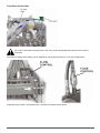
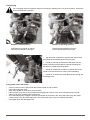
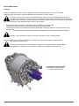
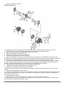
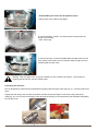
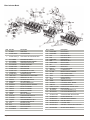
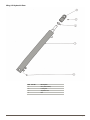
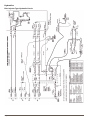
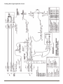
Operator Manual
& Parts List
MAJOR
SLURRY
INJECTORS
230310
Head Office
Major Equipment Intl Ltd
Ballyhaunis,
Co. Mayo,
Ireland
Tel.:
Fax:
09496 30572 09496 30788
UK Office
Major Equipment Ltd.
Major Industrial Estate.
Middleton Rd
Heysham
Lancs.
LA3 3JJ
Tel.:
Fax:
01524 850 501
01524 850 502
NL & GERMANY OFFICE
Major Equipment Intl Ltd
Postbus 29
NL-7700 AA
Dedemsvaart
Nederland
Tel: + 31 (0) 6389 19585
Web: www.major-equipment.com
We suggest that you record your machine details along with your dealers address & telephone
number for your convenience
MODEL:
______________ SERIAL NO:
__________________
DEALER:
________________________________________________________
ADDRESS:
________________________________________________________
________________________________________________________
________________________________________________________
TEL NO:
________________________________________________________
Disclaimer
While every effort has been made in the production of this manual to ensure that the information contained herein is full and correct, Major assumes no responsibility for errors or omissions.
Major reserves the right to modify the machinery and the technical data contained within the manual without prior notice.
Further to this, Major assumes no liability for any damages which may result from the use of the information contained within this
manual.
Contents
Introduction
Thank you1
Using Your Operator’s Manual 1
Safety Issues1
Product Identification
Machine Serial Numbers1
Purpose of Use 1
Product Specifications2
Register Your Product and Warranty Online2
Safety
Machine Safety Labels 3
Operating Safely4
Driving safely on public roads 4
Operating the Machine
Inspections before Use5
Key to Main Parts 5
Starting Regulations6
Machine Set Up6
Coupling the tanker to the tractor8
Coupling the Slurry Applicator to the Tanker10
Feed Hose Connection11
Operating the Machine12
Uncoupling the Injector from the Tanker14
Maintenance
Greasing schedule 16
Hydraulics 17
ExaCut Macerator18
Trouble Shooting21
Spare Parts
Spare Parts22
Introduction
Thank you
We appreciate having you as a customer and wish you many years of safe and satisfied use of your machine.
Using Your Operator’s Manual
This manual is an important part of your machine and should remain with the machine when you buy it. Reading
your operator’s manual will help you and others avoid personal injury or damage to the machine. Information given in
this manual will provide the operator with the safest and most effective use of the machine.
Sections in your operator’s manual are placed in a specific order to help you understand all the safety messages
so you can operate this machine safely. You can also use this manual to answer any specific operating or servicing
questions.
Safety Issues
Your manual contains special messages to bring attention to potential safety concerns, machine damage as well
as helpful operating and servicing information. Please read all the information carefully to avoid injury and machine
damage.
Product Identification
Machine Serial Numbers
If you need to contact MAJOR or your MAJOR dealer for information on servicing or spare parts, always provide the
product model and serial numbers.
We suggest that you record your machine details below:
Model No:
____________________________________
Serial No:
____________________________________
Date of Purchase: ____________________________________
Dealer Name:
____________________________________
Dealer Telephone:
____________________________________
The serial plate is loacted on the front side of the frame.
To show that the Major Disc Injector / Trailing Shoe
conforms to all the European rules, the CE-brand is
printed on the Major identify plate.
Purpose of Use
The slurry applicator is an agricultural machine which is exclusively developed for the injection of fluids in or onto
the soil with a limited amount of solid matter, like water or slurry. The slurry applicator should not be used for other
purposes other than applying slurry. Other applications outside the correct use can be dangerous.
Page 1
Product Specifications
MAJOR TRAILING SHOE
Hydraulic Requirements:
Hydraulic Flow Rate 50-70 L/Min
Max Pressure 200 Bar
Tractor Spools:
1. Double Acting – Macerator Motor
2. Double Acting - 6 Port Diverter
6 Port Diverter controls
Spool Position “A”
- Lifts the frame and closes the gate valve feeding
the macerator
Spool Position “B”
- Lowers Frame and opens gate valves. Gate valves
stay open until operator lifts frame.
•
Drain Port – Motor drain line
(Must be pressure free flow return)
MAJOR DISC INJECTOR
Hydraulic Requirements:
Hydraulic Flow Rate 50-70 L/Min
Max Pressure 200 Bar
Tractor Spools:
1. Double Acting – Wing Ram
2. Double Acting – KV-10 Sequence Valve
KV-10 Sequence:
1. Arms lower
2. Gate valves open
3. Motor rotates
•
KV-10 Reverse Sequence
1. Motor Stops
2. Gate Valve Closes
3. Arms Lift
Drain Port – Motor drain line
(Must be pressure free flow return)
Horse Power Requirements – 100 Hp +
PTO Requirements – 1000 PTO Rpm Max (Optimum efficiency 750E)
(Turbo Pump Model)
MAJOR DISC INJECTOR
Working width (m)
5.2
Weight (kg)
1260
Working depth
20 – 60 mm
Transport Width
2.4m (8ft)
Spreader outlet
40 mm
Spread Capacity
10 – 30 m3/ha (142 – 429 cuft/acre)
(3/4” - 2 1/2”)
TRAILING SHOE APPLICATOR
Working width (m)
6.4
6.8
7.7
Weight (kg)
1130
1130
1170
Transport Width
2.7m (8ft 8)
Spreader outlet
40 mm
Spread Capacity
10 – 30 m3/ha (142 – 429 cuft/acre)
Register Your Product and Warranty Online
To register your product through the Internet, simply go to the Support section on www.major-equipment.com.
Completing the information, either online or with the product warranty card, will ensure the customer that their product
receives all post sales service and important product information.
The MAJOR Shallow Disc Injector and Trailing Shoe are supplied with a twelve month warranty. No warranty is given
where the machine is being used as a hire machine. Warranty is against faulty workmanship or parts. All parts must
be returned to the manufacturer. No warranty can be considered unless parts are returned. All replacement parts will
be supplied on a chargeable basis until warranty has been accepted.
Page 2
Safety
Machine Safety Labels
The machine safety labels shown in this section are placed in important areas on your machine to draw attention to
potential safety hazards. Replace missing or damaged labels.
Read the user manual thoroughly before
use.
In front of the tank, on front of frame
Danger of entrapment
On the frame, both foldable sides
Grease Point
On the frame, near Hinge points
Don’t not run macerator dry
On the rear of macerator
Beware of High Pressure Oil Leaks.
On front of frame
Lift machine before reversing.
On front of frame
Do not insert hands during operation
Rear of the macerator.
Switch off machine before opening for
inspection
Rear of the macerator
Warning Danger of crushing between two
moving parts,
Right and left wing hinges.
Remove transport pin in linkage frame
before use
Diverter Hydraulic hoses near fittings.
Page 3
Operating Safely
Users should become thoroughly familiar with the contents of this manual before using, servicing and mounting the
implement to the tractor and all other pertinent operations. Never wear jewellery, loose clothing such as ties, scarves,
belts, unbuttoned jackets or dungarees with open zips which could become caught up in moving parts.
Always wear approved garments complying with accident prevention provisions such as non-slip shoes, ear muffs,
goggles and gauntlets. Wear a jacket with reflecting stickers if the implement is used near public highways.
Consult your retailer, the Labour Health Service or your nearest equivalent authority for the information about the
current safety provisions and specific regulations with in order to ensure personal safety.
ALWAYS DISENGAGE PTO, SWITCH OFF THE TRACTOR ENGINE AND ENGAGE THE PARKING BRAKE
BEFORE MAKING ADJUSTMENT TO THE MACHINE.
Sound Levels: The average measured sound-pressure level of a slurry injector is less than 70 dB (A). Take care,
the average sound-level of a slurry tanker can be more than 80 dB(A), it is therefore recommended that you wear ear
protection.
Driving safely on public roads
When the machine is used for transport on the public road, it must conform to all road safety regulations. For these
laws the Major Disc Injector / Trailing Shoe have a topped of triangle on the back of the frame, and road lighting in
accordance with the Roads Authority Transport.
Transport on the public road is only allowed when both wings are folded up and locked in position. Ensure the
machine is coupled together correctly and pins are retained.
Hydraulic connections: Check connections are clean before attaching, ensuring correct fitment and prevention of
internal damage.
Foldable parts: Do not allow people in the working area when folding or unfolding wings as there could be serious
injury and or loss of limb. Lock wings in position after folding.
Take account of the stability of the tanker while driving with a coupled Major Disc Injector / Trailing Shoe. Ensure
tractor is weighted correctly to balance steering.
Transport on a Trailer
Both wings of the slurry injector should be folded out
when transported on a trailer. Be aware of the total
height and width of a trailer with load.
The Major Disc Injector / Trailing Shoe can be tied up at
the following points:
At the lower linkage point (A);
At the upper lifting eyes (B
Page 4
Operating the Machine
Inspections before Use
Before transporting the combination of slurry tanker and slurry injector, the following points should be checked and
followed:
• Check the entire technical conditions of the machine.
• Check the locking pins of the linkages and wings are secure.
• Check the hydraulic system for leakages.
• Check the gate valves and couplings for leakages
• Check the lights are operating correctly.
• Check if the topped off reflective triangle is on the right place and visible
Key to Main Parts
Image 1: Coupled onto the slurry tanker
The MAJOR Disc Injector and the Trailing Shoe slurry applicators are mounted on the 4 point linkage of the slurry
tanker. Depending on the width and version of the machine, the slurry is pushed under pressure from the vacuum
tanker via the stone trap and through the Turbo chopper unit into the macerator/distributor feed hose macerator/
distributor. The Macerator chops the slurry into a fine pulp and distributes it between the hoses.
The Major Disc Injector uses the weight of the tanker to push the cutting discs into the ground, creating a groove. The
groove can be set in depth from 10 to 60 mm. The slurry is injected in this groove below the level of the ground. The
discs are held in pairs and follow the ground contours together. The Discs are of a three part construction and roll on
bearings
The Major Trailing Shoe model rests on the ground on its own weight with the slurry placed in the track left by the
shoe. For optimum application, the slurry must be well agitated before filling the tanker. The macerator is more prone
to blockages if the slurry is thick and heavy with grass.
Image 2: OVerview Slurry Applicator
The two side parts (wings) of the slurry injector are foldable,
so the machine is capable for transport on the public
roads. The distributor, frame lift and fold up cylinders are
hydraulically operated.
Page 5
Starting Regulations
Always check that any imminently dangerous conditions have been eliminated before using the machine. Ensure all
guarding is present and the operator is fully aware of the operations of the machine
Machine Set Up
Setting the wing level (all models)
If the wings of the slurry injector are not completely flat after unfolding (the outer discs or shoes are higher or lower),
then adjust in the following way:
• Unfold the wings of the machine;
• Loosen the lock nut;
• Lift the machine on one side with a jack;
• Using a wrench to rotate the piston rod until desired level is reached.
• Relock lock nut.
Page 6
Adjustment of working depth (This is for Major Disc Injector only)
Check that the wings are opened out completely to ensure the outside discs will have the same working
depth as the inner discs.
There are three steps in setting the working depth.
1. Set the depth to desired dosage per hectare: The depth can be adjusted independent to the desired dosage per
ha. A small dosage can be operated at a low depth, approx 2 to 3 cm depth. For a higher volume of slurry, increase
the depth to suit.
2. Adjust by hand: Adjust the top linkages to ensure the rubber boot slurry outlets are not rubbing on the ground.
3. Fixing the depth with pressure: The depth-adjustment is set using the KV10 Valve to a maximum of 80bar. See
the section “Operating Disc Injector” for more details on the working of the KV10 valve
Do not exceed 80 bar as damage may occur to the machine.
Page 7
Coupling the tanker to the tractor
1. Connect Hitch.
2. Connect Hydraulic hoses as per slurry applicator listed below:
Disc Injector Model.
Double Spool ½” Male Connection KV10 Valve.
Drain line
¾” Female Connection KV10 Valve and Macerator Motor Drain (free flow to tank)
Double spool ½” Male Connections Fold out Wings Cylinder
Trailing Shoe model
Double spool ½” Male Connections Macerator Motor.
Drain line
¾” Female Connection Macerator Motor Drain (free flow to tank)
Double spool ½” Male Connections 6 port diverter
N.B: Remove linkage transport safety lock before use! (See Image below).
The MAJOR Tanker is designed to be balanced correctly when coupled to the Slurry Applicator. Operation
of the tanker without the slurry applicator attached will cause more wear on the tractor hitch and the
machine will be more difficult to tow. It is advisable to fit a counterweight onto the 4 point linkage to balance
the machine.
A splash plate can attach onto the rear of the slurry applicator, therefore the slurry applicator need not be removed.
Page 8
3. Connect the Control box
Disc Injector Model
Position the Reverse Macerator Switch in the tractor cab &
connect 12v plug
Control Box (Image 8) reverses the rotation of the
macerator motor. Set Spool Valve to neutral & then operate
Control Box to change direction.
IMPORTANT: DO NOT OPERATE SWITCH
CONTINUALLY AS THIS MAY DAMAGE THE
MACERATOR MOTOR.
Trailing Shoe Model
Position the 6 Port Diverter Control Box (Image 9) in the
tractor cab & connect 12v plug
Set Spool Valve to neutral & then operate Control Box to
change operation.
Control box in top position (de-energized)
- Spool position ‘A’ :
- Lifts the frame & closes the gate valve feeding the
macerator.
- Spool position ‘B’
- Lowers Frame & opens gate valve. Gate valve remains
open until operator lifts frame.
CONTROL SWITCH MUST BE IN TOP POSITION WHEN
OPERATING & ENSURE TRACTOR SPOOL IS IN
‘FLOAT’ POSITION TO ALLOW OIL TO FLOW FROM LIFT
RAMS TO TRACTOR ALLOWING FRAME TO LIFT &
LOWER WITH GROUND CONTOURS WHEN APPLYING
SLURRY
Control box in side position (energized)
Lifts & lowers Trailing Shoe Wings from transport position
when alternating from spool position ‘A’ & ‘B’
4. Attach the cable of the lights to the socket (standard 7-contact plug).
5. Connect Brake hoses.
6. Connect PTO Shaft as described in Tanker manual after checking for length.
NOTE: Some tractor manufacturers fit pressure relief on one side of the tractor spools (e.g. John Deere).
If the hydraulic connection for lifting the frame is connected to this side of the spool then the frame will lower
automatically with the spool in neutral position. To remedy this action swap the hydraulic hose connections.
Consult tractor manual or your Tractor dealer for more information.
Page 9
Coupling the Slurry Applicator to the Tanker
Never couple or manoeuvre if somebody is between the slurry injector and the slurry tanker.
Only attach or detach hydraulic connections when the tractor is switched off. Make sure the hydraulic
valves and electric cables are coupled in a way that there is not a chance of damage.
Connect the following while referring to the image below.
•
•
•
•
Connect Lower Linkage
Connect Top Links
Connect Trap with 4” Feed Hose
Connect Hydraulic hoses:
- ¾” Male Connections Macerator Hydraulic Motor.
- ½” Female Connection Macerator Hydraulic Motor Drain
- ½” Male Connection Fold out Wings Cylinder
•
•
•
Couple the 4” hose feed from the slurry tanker to the distributor.
Take both support legs away if the slurry injector is coupled and locked for transport.
Attach the lights cable to the socket (standard 7-contact plug).
NOTE: Lock Frame Lift Hydraulic Rams in Transport position with the lever tap located on the rear of the
chassis. This allows the operator to disconnect and reconnect the quick release fittings from tractor with
ease.
NOTE: Operate Frame Hydraulic Rams smoothly using tractor spool as linkage will drop quickly. This quick
action allows the Injector Frame to follow the ground contours with ease.
Page 10
Feed Hose Connection
Do not fit an automatic reversing valve to the circuit as this will damage the hydraulic motor and the
macerator
The speed of folding and unfolding can be adjusted by turning flow controller in or out (see image below).
Depending upon model – the hydraulic flow controller is located as shown above.
Page 11
Operating the Machine
Disc Injector
Do not operate the macerator motor without slurry in the distributor or damage can occur.
System with KV10 Valve Sequential Valve
Unfold the Wings and check if the slurry injector is flat in the width
Operate Sequential Valve on separate spool, this will automatically:
•
Lower frame
•
Open rear gate valve and stone trap gate valve.
•
Start Hydraulic Motor.
N.B. The clinchers open mechanically, when the machine is put on the soil;
Start driving forward at a suitable speed. When turning at the headlands or when finished working the machine,
Lift main frame to clear the ground by operating the KV10 Valve in reverse. This will:
•
Stop Hydraulic Motor
•
Close Gate Valves
•
Lift Frame
Fold in both foldable parts of the slurry injector when finished and lock in
position.
For models without KV 10 Valve
Unfold the Wings and Check if the slurry injector is level.
Put the slurry injector with the cutting discs into the soil by putting down
the lifting device of the slurry tanker;
N.B. Both injectors open the clinchers (rubber boot seal) mechanically,
when the machine is put on the soil;
Adjust the right working depth according to one of the methods previously
described
Open the gate valve from the slurry tanker and start with driving. The
manure will stream directly out of the outlets;
N.B. When the gate valve is opened before the clinchers are opened, the
pressure can be too high and a seal can burst open.
First close the gate valve and then close the clinchers at the end of the
parcel. The clinchers will prevent leaking of manure;
When Finished
Lift the slurry injector with the linkage off the ground;
Fold in both wings on the slurry injector and lock in position.
Trailing Shoe
6 port diverter:
The trailing shoe hydraulics operates through a 6 port diverter. The six port diverter has two spool settings. These
settings are operated by the in cab control box (Ref P.11)
•
Spool position ‘A’: Lifts the frame and closes the gate valve feeding the macerator.
•
Spool position ‘B’: Lowers Frame and opens gate valve. Gate valve remains open until operator lifts frame.
Unfold the wings and check that the trailing shoe applicator is flat. Select position ‘A’ on the control box and lower
frame, the gate valve will automatically open. Start hydraulic macerator motor.
When finished
Switch off macerator motor. Select position ‘B‘ on the control box and raise frame. This will shut off the gate valve
feeding the macerator.
Page 12
Turbo Pump
Do not engage Turbo Pump gears while PTO is turning or damage can occur to the machine. Ensure the
levers are detented in position.
Handles in neutral position
Handles in operating position
Centrifugal pump handle on the left
vacuum pump handle on the right
Centrifugal pump handle on the left
vacuum pump handle on the right.
Slurry Flow Controllers
• Adjust the flow controllers to optimise the output of the
pump against the forward speed of the machine.
• Handle ‘A’ controls the macerator feed valve and can
be left in position as the hydraulic gate valve feeding the
macerator is closed when filling tanker.
• Handle ‘B’ controls the macerator overflow and can be
varied to remove the excess of slurry when spreading.
• Handle ‘B’ is opened fully when filling tanker through the
centrifugal pump
Filling tanker with Turbo Pump
•
•
•
•
•
•
•
Connect vacuum hose to either turbo filler inlets located on side of tanker.
Close stone trap gate valve
Open fully, handle ‘B’ on the slurry flow controller
Place vacuum pump into vacuum position and engage both vacuum pump and centrifugal pump into gear
Start PTO & prime centrifugal pump with slurry
Once Centrifugal pump engages, continue to fill tanker when tanker is full, Slurry will exit through the yellow overflow hose & into the centrifugal pump. This will prevent more slurry from entering the tanker.
Close gate valve and disengage PTO.
Page 13
ExaCut Macerator
The ExaCut can be used on pump tankers and vacuum tankers. The pump tanker must be supplied with a pressure
limit of 3 bar. This is possible using a pressure relief valve (optional). For control purposes, we recommend a pressure
gauge on the liquid manure pipe.
Achievable flow rate:
The maximum flow rate depends on the proportion of dry matter, the type of liquid manure, the pressure of
the spreading vehicle, the cutting ring hole size and the rotor geometry.
Required pressure:
To achieve a good average distribution, the pressure in the spreader needs to be from 0.2 bar. That means
that, with low viscosity media, you achieve a better average distribution with a higher flow rate.
Please observe the following operating instructions:
• The ExaCut must be switched on shortly before the media flows through it.
• To prevent increased wear, a dry run of the ExaCut of more than 30 seconds should be avoided.
• The direction of rotation should be changed at regular intervals. Depending on the connector, this can be achieved by redirecting the control unit or by a timed electromagnetic valve. This guarantees the best self-sharpening
of the blades.
• As a small amount of liquid manure can leak from the suction pipes, short hoses should be connected which can
be guided with the drain hoses. You also simplify cleaning the ventilation if you use a water hose.
Uncoupling the Injector from the Tanker
The Shallow Disc Injector / Trailing Shoe should be uncoupled on stable, flat and horizontal ground. If the slurry
injector is stored with both wings folded up, then those parts should be locked. If the machine is not to be used for a
long time, then it is recommended to open the wings out. Keep the following points in mind when uncoupling.
•
Put the support legs in the right place and lock (see picture below).
•
•
•
•
•
Let the slurry injector down using the tanker linkage.
Switch off the tractors engine.
Ensure the hydraulic valves are not pressurised, uncouple them from the slurry tanker. Put the valves in position to guarantee they remain clean.
Uncouple the light socket from the slurry tanker and store the cable;
Uncouple the slurry injector from the linkage arms.
Be aware of downward forces when uncoupling the slurry injector.
Page 14
Technical data for the hydraulic motors
Motor type
OMS 125
OMS 160
OMS 200
OMS 250
VOGELSANG item no.
AOM.016
AOM.015
AOM.017
AOM.018
32
32
32
32
cont.
600
470
375
300
int. 1)
720
560
450
360
cont.
210
210
210
200
int. 1)
275
260
250
250
peak 2)
295
280
270
270
cont.
375
490
610
720
int. 1)
490
600
720
870
cont.
75
75
75
75
int. 1)
90
90
90
90
cont.
230
230
230
230
int. 1)
295
295
295
295
peak 2)
300
300
300
300
Ø Shaft
max. speed of rotation [min-1]
max. drop in pressure [bar]
max. torque [Nm]
max. oil flow [l/min]
max. inlet pressure [bar]
max. return pressure with oil
leakage pipe [bar]
max. return pressure without oil
leakage pipe [bar]
cont.
140
140
140
140
int. 1)
175
175
175
175
peak 2)
210
210
210
210
cont.
30
35
45
50
int. 1)
75
75
75
75
1) Intermittent operation: the permissible values may be reached max. 10% of every minute.
2) Peak performance: the permissible values may be reached max. 1% of every minute.
Page 15
Maintenance
Injectors
Maintenance must be carried out by qualified personnel. To make sure that all parts of the Disc Injector / Trailing
Shoe function properly, the machine has to be cleaned regularly. Clean the machine after use (daily). Do not use a
high pressure cleaner.
Greasing schedule:
Follow the schedule below using EP2 or an equal type of grease. Standard hydraulic tractor oil can be used for
hydraulic oil.
When
Where
How
Daily (after use)
Bearings of the rolling coulters
Grease nipple
Bearings at both turn points of the foldable parts
Grease nipple
Stub axles
Grease nipple
Supports of valves
Grease nipple
Hydraulic system
Refresh hydraulic oil
Weekly
1000 work hours or
every two years
Check the following points regularly:
•
•
•
•
•
•
•
Check the gate valves for jams damages / leakages;
Check the hydraulic valves for damages / leakages;
Check the hydraulic connections for damages / leakages;
Check the hydraulic cylinders and packing for leakages;
Check if the fastening bolts of the linkage device are tightened.
Check the linkage device for metal fatigue and cracks;
Check the pivot points folding parts for damage.
Check the fasteners for tightness:
Disc Injector
Trailing Shoe Applicator
•
Linkage mounting
•
Linkage mounting
•
Linkage pivot pins
•
Linkage pivot pins
•
Wing Pivots
•
Wing Pivots
•
Steering arm Horizontal Pivots
•
Spring Mounting bolts (both ends)
•
Steering Arm Vertical Pivots
•
Coulters
•
Cutting Disc Axle Nuts
Page 16
Vogelsang Hose layout
Hydraulics
NOTE: Hydraulics will ‘Lock out’ if Drain line is not connected to free flow return in Tractor
KV 10 Sequence Valve (Injector models only)
Sequence
Return Sequence
•
Arms lower
•
Stop Hydraulic Motor
•
Gate valve opens
•
Close Gate Valve
•
Motor rotates
•
Lift Frame
The lift ram valve should remain opened out if this valve
is used on the trailing shoe model or the frame will be
forced downwards which could damage the springs.
KV 10 Set up
Adjust valve ‘X’ to offer a maximum flow 60 litres / min to
the macerator motor
Set lift ram valve to 40 bar. Adjust valve X to compensate
flow loss to motor.
Adjust Lift Ram Valve to desired pressure. Adjust Valve
X to compensate, fine tune valve X to remove noise from
valve.
Page 17
ExaCut Macerator
Cleaning
Remove foreign bodies, such as stones, regularly through the cleaning port (pos. 40 in fig. “Exploded
drawing ExaCut wear parts”) - (intervals depend on the proportion of foreign objects.
To keep the air duct in the interior of the distributor free, water should be sprayed regularly into the air
lines when the distributor is running slowly. This work step is made easier by attaching short hoses to the
ventilation pipes. Excentrics must be checked for mobility at regular intervals and, if necessary, dismantled
and made operational. After dismantling the excentric, tension again.
•
•
•
Before long breaks in operation, the ExaCut must be cleaned by spreading water.
The ExaCut is cleaned with open maintenance ports and checked for wear.
Lubricate the hydraulic motor adapter with ample grease after cleaning to protect the contact surfaces of the sealing rings.
•
All cutting surfaces should be sprayed with biodegradable oil before longer breaks in operation.
Warning: First of all switch off the PTO and put the hydraulic valve in floating position.
Open the cleaning port and let the distributor run empty. Then unscrew the lateral maintenance port
and grease the cutting parts.
Warning! If the housing cover is dismantled for cleaning, the excentric adjusters slacken. Before
reassembling the housing cover, the excentric adjuster must be tightened and secured.
Lubricating the grease nipples
Lubricating the grease nipples:
• every 50 operating hours
Page 18
• before long breaks in operation
Replacing wear parts
The cutting knives must be replaced if the driver plate of the rotor is sticking out of the cutting knife 8-10mm.
1. Switch off the PTO motor / spreading vehicle, put the hydraulic valve into floating position.
2. Open the cleaning port [pos. 40] and let the distributor run empty.
3. Open the maintenance port [Items 24+23].
4. Unscrew the housing cover [Item 1] of the ExaCut.
5. Unscrew the screw [Item 17] in the rotor [Item 7].
6. Pull out the distributor rotor [Item 7]. Pay attention to the shims [Item 20]. If the distributor rotor is stuck, with
ExaCuts from construction year 12/2002, you have the possibility of pulling off the rotor using an M30 hex head screw
(see the chapter on “Disassembling the rotor from the hydraulic motor using an M30 hex head screw”).
7. Remove the cutting ring nuts [Item 5] from the rear side and remove the cutting rings [Item 4]. Before installing
the new cutting rings, clean the contact surfaces and coat the area around the threaded bolts with seal agent, for
example, silicone. When tightening the nuts, observe the max. tightening torque of 28Nm.
8. Check lip seals and bushing [Item 9] for wear and replace if necessary.
9. Lubricate the ring gasket, foam PU [Item 8] and replace if worn.
10.Clean the cover seal [Item 21] and examine for damage.
11. Tension the excentric [Item.11] with the help of a small pair of water pump pliers and secure it using a spring
cotter.
12.Place the cutting knives [pos. 6] on the rotor.
13.Lubricate the bushing [Item 9] on the rotor, assemble the rotor [Item 7] with a light rotational movement to protect
the lip seal. Pay attention to the shims [pos. 20] and distance bushing [Item 18] with O-ring [Item 19] between the
rotor and the hydraulic motor.
14.Assemble the cover [Item 1].
15.Check whether the rotor is positioned in the middle and, if necessary, balance the shims.
16.Remove the spring cotter (you should hear a clicking sound - the excentric is turning), close the cleaning port
[Item 40] and the maintenance port [Items 24+23].
Page 19
Disassembling the rotor from the hydraulic motor
Remove the screw, washer and gasket.
To centre the shims, a M10x * hex head screw is inserted into the
boring in the bushing.
* max. 30mm long
To remove the rotor, screw a lubricated M30 hex head screw into the
rotor. After the hex head screw is screwed in deep enough, the rotor
releases itself from the motor.
Warning: With very tight rotors, it may be necessary to first of all pull it out approx. 12mm without a
centering bolt and to then use the centering bolt.
Tensioning the excentric
First of all tighten by hand and secure behind the leg spring with the spring cotter (see fig. “A”). Gloves protect from
injury.
Tighten the rest using a pair of water pump pliers until the borings are aligned. Then secure using the spring
cotter [fig. “B”]. Do not remove the spring cotter through the opening of the maintenance port until after assembling
the housing cover.
Page 20
Trouble Shooting
Injector
Fault
Injector wont drop
Frame does not follow ground
contours
Macerator will not spin
Cause
Remedy
Hydraulic tap is closed
Open hydraulic tap
Transport lock is still in place
Remove locking pin
Hydraulic linkage is pressurised
Put hydraulics in float position
Low flow rate/ Oil pressure
Check hydraulic flow rate set to running
specifications
Macerator shear plate blocked
Empty macerator by opening bottom
stone trap. Open inspection port and
clear any blockages.
KV-10 valve incorrectly set
Refer to previous page
Cause
Remedy
Rotor runs too slowly
Check the hydraulics
Rotor is clogged
Clean the ExaCut
Ventilation is blocked
Clean the ventilation ducts from
outside using a water hose
Liquid manure flow rate
excessive
Reduce the pump speed
Cutting knives worn
Replace the cutting knives
Pre-tensioning part(s) defective
Replace pre-tensioning part(s)
Cutting knives do not move
Make cutting knives operational
Rotor runs too slowly
Check the hydraulics
Rotor speed too low/too high
Check the oil flow rate of the PTO
Pressure in pot too low
Increase the delivery rate quantity
Hoses laid wrongly
Refer to hose laying diagram
ExaCut Macerator
Fault
ExaCut vibrates
Cutting force insufficient
Bad distribution
Fibrous matter under the cutting knife Remove fibrous matter
Only a few hoses are fed with
medium
Rotor blocked
If possible, reverse the rotor several
times
Remove blockage
Check the hydraulics
Cover cannot be
assembled
Excentrics are not preloaded
Preload excentrics
Page 21
Turbo Injector
Macerator / Distributor
Item Part No
Description
Item Part No
Description
1
TDE.701.N1
Cover
15
NUS.001
Washer
2
GRS.083
Sleeve packing
16
DKR.009
Copper ring
3
TFL.715
Cutting ring (Large holes (Standard))
17
NSK.060.EE
Hex head screw
3
TFL.716
Cutting ring (Small holes)
18
TRS.011
Bushing
3
TFL.717
Cutting ring (Extra large holes)
19
DOR.021
O-Ring
4
TMS0002
Blade ring
20
NUS.067
Shim
5
TMH0003
Blade holder
23
DFD.356
Gasket maintenance port
6-13 TRO.709
Rotor complete
24
TFL.504.N1
Maintenance port
6
NIR.023
Inner ring
25
NGS.031
Stud
7
TRO.708
Rotor
26
NMK.002
Hex nut
8
DFD.116
Ring gasket, foam PU
9
TFL.677
Channel
27
TRS.082
Adaptor for hydraulic motor
10
TFL.676
Channel
28
NSR.025
Retaining ring
11
TEV.005.N1
Eccentric adjuster
29
DWD.050
Lip seal
12
NUS.003.E
Washer
30
NUS.060
Washer
13
NSK.208
Hex head screw
31
NGE.094
Screw connection
14
DFD.115
Gasket ABIL
32
NKS.012
Grease pipe
Page 22
27-31 TAS.015
Adaptor for hydraulic motor complete
Macerator / Distributor
Item Part No
Description
Item Part No
Description
33
NGE.093
Screw connection
41
NMS.004
Hex nut
34
NKS.001
Grease pipe
42
BKA.001
Grease nipple cap
35
TEE.110
Pipe nipple
43
TFD.021
Foam rubber
36
HRS.163
Tube coupling
44
TEG.701.N1
Housing
37
AOM.018
Hydraulic motor
45
NSZ.005
Cylinder pin
38
NPF.053
Key
46
NGS.032
Stud
39
NGS.049
Stud
47
NMK.020
Eye nut
40
NUS.005
Washer
48
NMK.001
Hex nut
Parts & Macerator Feed Pipework from Turbo Pump
Item
1
2
3
4
5
6
7
8
9
10
11
12
13
14
15
16
17
18
19
20
Part No
TA-LF04
JET26
JET28
JET9
LGP-DH050
TA-5HB-001
TA-5HB-010
TA-GF-24
TA-GF-P
TA-GF023
TA-GF027
TA-GF030
TA-INJ-GJMP
TA-INJ-PB-J
TA-INJ-PB-K
TA-LBB01
3722161
4716601
5101150
5101170
Description
LINKAGE ASSEMBLY
TRAP-JOINT OUTLET
8” TO 6” REDUCER
TRAP-HOSE OUTLET
SWIVEL HITCH (EXTENDED)
5”” HOSE BRACKET ASSY
5”” HOSE BRACKET ASSY
TOP OVERFLOW
GARDA FILLER MOUNT
STONE TRAP BEND
GARDA FILLER STONE TRAP
BLASTER MANIFOLD
FEED PIPE
4” 45 BAUER COUPLING
BAUER-4 BOLT FLANGE COUPLING
FLASHING BEACON BRCKT
6” PIPE FLANGE SEAL
O RING
HOSE CLIP 162-174
HOSE CLIP (227-239)
Item
21
22
23
24
25
26
27
28
29
30
31
32
33
34
35
36
37
38
Part No
AG113-121
AG21B
BA305/4
BA309/4
BP1101/G
BP1101/H
G75-8
M12
M12x120BZP
M12x35BZP
M12x40BZP
R1716/6
R1716-6H_
Working
TA-GF036
TGRE100-2b
TGRE100-3
TGRE100-2
TA-INJ-HH01
Description
HOSE CLIP 113-121
IMPELLER HOUSING GASKET
BAUER SEALING RING
4” BAUER MALE COUPLING/PIPE END
6” FLEXIBLE CONNECTOR
8” CONNECTOR
GARDA +MEC 8000
M12 NYLOC NUT
M12x120 BOLT
M12x35 BOLT
M12x40 BOLT
6” GATE VALVE
6” GATE VALVE c/w ROD
4” LAYFLAT HOSE
100mm Front Macerator Feed Hose
100mm Macerator Rear Feed hose
100mm Turbo Filler hose
COUPLING PLATE
Page 23
Linkage Frame
Item Part No
1
TA-LF01
2
TA-LF21
RAM SPACER
3
1/F
1” FINE NYLOC NUT
4
1x7FBZP
1”x7” FINE BOLT
5
FW1
DIA 1” FLAT WASHER
6
Gras-150
LABEL
7
INJ-RAM
RAM
8
INJ_RAM_R
CAT 2 TOP LINK ROD
9
849
GREASE NIPPLE M6 STR
10
1233
ROLL PIN DIA10x50
11
1500
SPLIT PIN 1/8”x1 1/2”
12
TDA-1T
PIVOT PIN (155)
13
TA-LF03
LINKAGE ASM
14
TA-LF26
HYDRAULIC RAM FRONT PIN
Trailing Shoe Slurry Injector
Parts
Item Part No
Page 24
Description
INJECTOR LINKAGE
Description
1
SA-TSCF-GA
CENTER FRAME ASSY
2
SA-TSWFL-GA
WING ASSY (LEFT)
3
SA-TSWFR-GA
WING ASSY (RIGHT)
4
SA-RAM
TRAILING SHOE RAM
Trailing Shoe Centre Frame Parts
Item Part No
Description
Item Part No
Description
1
BA349D4Z
BAUER 4” COUPLING
19
M12
M12 NYLOC NUT
2
OM028-6S
SHORT 6” MALE CONNECTION
20
M12x30SZP
M12x30 SET BOLT
3
SA-TSCF001
CENTER FRAME
21
M12x40BZP
M12x40 BOLT
4
SA-TSCF035
TOP LINK SPACER
22
M12x50BZP
M12x50 BOLT
5
SA-TSLB31
SAFETY MOUNT
23
M14
M14 NYLOC NUT
6
SA-TSMM01
MACERATOR MOUNT
24
OM11D6Z
6” FEMALE CAP
7
SA-TSMM20
MACERATOR INLET MOUNT
25
S112
CAT 2 PIN DIA 28.5x159mm
8
SA-TSPP01
WING PIVOT PIN
26
15501
CAT 0 PIN DIA 16x97mm
9
SA-TSSTD01
TRAILING SHOE STAND
27
S318-A
CAT 2-2 TOP LINK
10
SA-TSTS-GA
TRAILING SHOE ASSY
28
3546
LINCH PIN DIA 9.5
11
SA-MDI-FA13 MACERATOR FILL PIPE
29
37
LINCH PIN DIA 6
12
SA-MTS-M03
SPLASH PLATE MOUNT
30
49404
SPAREX 3/4” PIN
13
TA-SPP025
4” SPOON SPLASH PLATE
31
80
CAT 2 PIN DIA 25.4x142mm
JUBILEE CLIP 38-50
14
1/F
1” FINE NYLOC NUT
32
TF088
15
3722161
6” PIPE FLANGE SEAL
33
TVTE127
5” SLURRY HOSE - GREEN
16
AG131-139
HOSE CLIP 131-139
34
SA-TSMM15
INLET MOUNT
35
A-TSPP15
Washer
17
EXA30-40
Vogelsang EXACUT Macerator
18
Gras-128
SLOW MOVING VEHICLE
Page 25
Trailing Shoe Parts
Item Part No
Item Part No
Description
Description
7
SA-MDI-FA11
RAM SPACERS
8
FWM12
M12 FLAT WASHER
9
LA16812
LED CONTINENTAL LIGHT
10
LC2700
TRIANGLE REFLECTOR
11
M10
M10 NYLOC NUT
12
M10x100BZP
M10x100 BOLT
13
M12
M12 NYLOC NUT
14
M12x30SZP
M12x30 SET BOLT
15
M12x35BZP
M12x35 BOLT
16
MOT75
DIA 105x75 BUFFER
1
SA-TSLB01
LIGHT BRKT
17
1234
ROLL PIN DIA 10x60
2
SA-TSLB21
PIPE CLAMP
18
820
GREASE NIPPLE 1/8” STR
3
SA-TSTS-GA
TRAILING SHOE ASSY
19
8T19
BUFFER SPACER
4
SA-TSWF001
WING FRAME (RH)
20
SA-TSWF025
PIVOT SPACER
5
SA-TSWH-GA
WHEEL ASSEMBLY
21
TA-LGPLITR
LGP LIGHT BRACKET (RH)
6
SA-MDI-FA05
WING RAM PIN
22
TA-LGPLITL
LGP LIGHT BRACKET (LH)
Trailing Shoe Parts - Detail
Item Part No
1
SA-TSTS010
Description
SHOE ARM
Item Part No
11
M12x30SZP
Description
M12x30 SET BOLT
2
SA-TSTS020
STOP OFF ASSY
12
M12x90BZP
M12x90 BOLT
3
SA-TSTS030
STOP OFF LINKAGE BRKT
13
M8
M8 NYLOC NUT
4
SA-TSTS040
2” MALE COUPLING
14
S11074
TURNBUCKLE DIA 11xM8
5
1076Z250
RUBBER BOOT
15
2765
5/16” ‘D’ Shackle
6
DU4806-M
SPRING TINE
16
TF088
JUBILEE CLIP 38-50
7
M10
M10NYLOC NUT
17
TF090
JUBILEE CLIP 50-65
8
M10x30SZP
M10x30 SET BOLT
18
SA-TSTS060
COULTER
19
SA-TSTS050
TINE CLAMP
9
M10x40BZP
M10x40 BOLT
10
M12
M12 NYLOC NUT
Page 26
Disc Injector
Disc Injector Steerage & Clamp Assembly
Item Part No
11
Item Part No
M10x100BZP
Description
M10x100 BOLT
12
M10x30SZP
M10x30 Set Bolt
13
M12
M12 Nyloc Nut
14
FMW12
WASHER
15
M12x120BZP
M12 x120 Bolt
16
M12x90BZP
M12x90 Bolt
17
M16
M16 Nyloc Nut
Description
18
M16 x 180BZP
M16x180 BOLT
19
849
Grease Nipple M6 STR
1
SA-MDI-SA26
Steering Arm Main Frame
2
SA-MDI-DASM
Disc Assembly
20
850
Grease Nipple M8 STR
3
SA-MDI-SA01
Steering Arm
21
S11537
M10 x DIA 60 U-Bolt
4
SA-MDI-SA04
Stop Arm Asm
22
SA-MDI-SA17
Lay-Flat Hosing
5
SA-MDI-SA30
Stop Arm Top Asm
23
SA-MDI-SA33
Long Spring (Heavy)
6
SA-MDI-SA42
Suspension Arm
24
SA-MDI-SA34
Short Spring (Light)
7
FWM10
M10 Flat Washer
25
SA-MDI-SA35
Rubber Boot
8
FWM12
M12 Flat Washer
26
TF090
Jubilee Clip 50-65
9
FWM16
M16 Flat Washer
27
SA-MDI-SA08
Stainless Cover Plate
10
M10
M10 Nyloc Nut
28
SA-MDI-SA12
Spring Bushing Plate
Disc Injector Cutter Assembly
Item Part No
Description
1
6205
52x25x15 DEEPGROOVE
2
1089C
DISC (OUTER DU1052-)
3
1058
DISC (CENTER DU1059)
4
M20
M20 NYLOC NUT
5
SA-MDI-DA01
DISC BRG HOUSING
6
SA-MDI-DA02
DISC SHAFT
7
SA-MDI-DA03
DISC SPACER
8
SA-MDI-DA04
BEARING WASHER
9
851
GREASE NIPPLE
Disc Injector Wing
Item Part No
Description
1
SA-MDI-FA05
WING RAM PIN
2
MOT75
DIA 105x75 BUFFER
3
M20x240BZP
M20 BOLT
4
M20
M20 NYLOC NUT
5
SA-MDI-SAM-II DISC INJECTOR STEERING ARM
6
SA-MDI-WF01
WELDED WING ASSEMBLY
7
SA-MDI-FA10
DI WING HINGE PIN
8
FWM20
M20 WASHER
Page 27
Disc Injector Body
Item Part No
Description
Item Part No
Description
1
DI-RAM
WING RAM
32
M12x40BZP
M12x40 BOLT
2
SA-MDI-WF20
LIGHT BRACKET
33
M12x50BZP
M12x50 BOLT
34
M14
M14 NYLOC NUT
35
M16
M16 NYLOC NUT
36
M16x50BZP
M16x50 BOLT
37
M20
M20 NYLOC NUT
38
M20x240BZP
M20x210 BOLT
39
M8
M8 NYLOC NUT
40
M8x25BZP
M8x25 BOLT
41
MOT75
DIA 105x75 BUFFER
42
OM11D6Z
6” FEMALE CAP
43
PP-18M
METRIC DOWTY WASHER
44
1234
ROLL PIN DIA 10x60
45
15501
CAT 0 PIN DIA 16x97mm
46
37
LINCH PIN DIA 6
47
49404
SPAREX 3/4” PIN
48
TF088
JUBILEE CLIP 38-50
49
TVTE127
5” SLURRY HOSE - GREEN
50
VRB-02C
FLOW RESTRICTOR
51
VRDE-15-FF-38
DOUBLE PILOT CHECK VALVE
52
SA-TSMM15
INLET MOUNT
53
TA-LGPLITL
LGP LIGHT BRACKET (LH)
TA-LGPLITR
LGP LIGHT BRACKET (RH)
3
SA-MDI-SASM_II
DISC INJECTOR STEERING ARM
4
SA-TSMM01
MACERATOR MOUNT
5
SA-TSMM24
MACERATOR INLET MOUNT
6
SA-TSSTD01
TRAILING SHOE STAND
7
SA-TSTS040
2” MALE COUPLING
8
SA-MDI-FA05
WING RAM PIN
9
SA-MDI-FA11
RAM SPACERS
10
SA-MDI-FA13
MACERATOR FILL PIPE
11
TA-SPP025
4” SPOON SPLASH PLATE
12
SA-MDI-CF47
TRIANGLE MOUNT
13
1MB-18-06
18MM METRIC X 3/8 BSP M/M
14
AG131-139
HOSE CLIP 131-139
15
CRE100
ACCUMULATOR STRAP
16
EFM90-38
3/8” F/M ELBOW
17
EMM38
3/8” M/M CONNECTOR
18
EXA30-40
Vogelsang EXACUT Macerator
19
FWM12
M12 FLAT WASHER
20
FWM16
M16 FLAT WASHER
21
FWM20
M20 FLAT WASHER
22
FWM36
M20 Washer
54
23
FWM8
M8 FLAT WASHER
24
Gras-128
SLOW MOVING VEHICLE
55
SA-MDI-CFWA
CENTRE FRAME WELDED ASM
25
H14OOR
80BAR Accumulator
56
SA-MDI-FA10
DI WING HINGE PIN
26
LA16812
LED CONTINENTAL LIGHT
57
SA-MDI-WF01
WELDED WING ASSEMBLY
27
LC2700
TRIANGLE REFLECTOR
58
SA-MDI-WF01-H
DISC INJ WING LH
28
M10
M10 NYLOC NUT
59
SA-MTS-CF42
6” STONE TRAP
29
M12
M12 NYLOC NUT
60
SA-MTS-CF47
WELDED 4” BAUER FEM COUPLING
30
M12x30SZP
M12x30 SET BOLT
31
M12x35BZP
M12x35 BOLT
61
SA-MTS-M03
SPLASH PLATE MOUNT
Page 28
Wing Lift Hydraulic Ram
Item Part No
Description
1
Ram (State Model)
2
Locking Nut
3
Adjustable end
4
Bolt
Page 29
Hydraulics
Disc Injector Type Hydraulic Circuit
Page 30
Trailing Shoe Type Hydraulic Circuit
Page 31
Chopper Pump Parts
Item
G1/MEC
Part No
Description
4010301004 Gearbox GARDA / MEC
G 1/MEC-TS 4010301024
Gearbox GARDA / MEC TURBO
SYSTEM
Qty
Item
Part No
1
G7
4030108008 Front and back cover gasket
2
G8
4010007001 Shoe for gear
2
G9
5050507002 Circlip Ø 12 E
1
G10
5050507003 Circlip Ø 25 E
1
1
Gearbox WPT - GARDA / MEC
G 1/MEC-TS 4010301024
TURBO SYSTEM
G 5/540
G6
Page 32
4020807001
Central gear wheel 540 RPM Z 97
-M3
4010601020 Front cover (75)
Description
Qty
1
G11
5050107020 Screw M 10x25 TE
12
G12
5012107010 Ball bearing 6307
3
1
G13
4010601021 Gearbox cover
1
Item
Part No
G 14
5050107028 Screw M 12x35 TE
4
G 15
5050207009 Blank washer Ø 8x32
1
G 16
4010006001 Gearshift fork GARDA
1
Qty
G 17
4011907001
1
G 19
5050107009 Screw M 8x20 TE
7
G 20
5050207004 Smooth washer Ø 10
20
G 21
5060605001 Oil plug Ø 3/8” Gas
1
G 22
4030108009 Front cover gasket
1
G 23
5050107018 Screw M 10x16 TE
1
G 24
5050202002 Aluminium washer Ø 10x16
G 25
Item
Part No
G 62 / 1000 4020907003
Description
Qty
Centrifugal shaft for preshaped ring
GARDA 1000 RPM
1
G 66
4020807003 Central gear wheel with idle gear
1
G 67
Centrifuge shaft for preshaped ring
4020907008
+ idle gear GARDA 6500
1
G 68
4011703001
Bushing Ø 30x40x60
1
G 71
4011101002
Scroll GARDA 3500
1
G 72
5030210006 Ring seal OR 4950
1
G 73
4011219002
Impeller GARDA 3500
1
1
G 74
4011001007
Scroll and impeller support for
preshaped ring GARDA 3500
1
5030300005 Oil seal 35x62x10
1
G 75
5030210017 Rubber ring HL 150
1
G 26
4020907001 Splined central shaft
2
G 77
5050107045 Screw M 12x30 TSEI
4
G 27
4010801003 Gear lever
1
G 78
4030111002
Preshaped ring Ø 40x56x8
4
G 28
5060105004 Oil level plug Ø 3/8” Gas 1
G 79
4011301002
Cordholder
1
G 29
4030109007 Gearbox cover gasket
G 80
5050303001 Brass nut M 10
2
G 30
5050207010 Blank washer Ø 30x56 1
G 81
4050412002 Stud bolt M 10x64
2
G 31
4012007003 Spring
G 82
4030108025 Scroll support gasket
1
G 32
5030300008 Oil seal 19x27x6 1
G 84
4010401028 Connection flange GARDA 3500
1
G 33
5010007002 Steel ball Ø 8.73 1
G 85
Centrifugal shaft for preshaped ring
4020907004
GARDA 3500
1
G 34
4020907002
G 86
5050707006 Key 8x7x35
1
G 35
5012107014 Ball bearing
G 87
Centrifuge shaft for preshaped ring
4020907005
+ idle gear GARDA 3500
1
G 36
5050707007 Key 8x7x50 1
G 88
4010401029 Closing flange
1
G 37
5050300003 Self-locking nut M 30x2 1
G 89
4010006005 Blade
1
G 90
4010006006 Counter-blade
1
G 38
4011001001
1
G 91
4010401027 Blade-holder flange
1
4010007002 Extension
1
1
Gear pin
Centrifugal shaft for preshaped ring
GARDA 6500
Scroll and impeller support for
preshaped ring GARDA 6500
1
1
1
G 39
5050107027 Screw M 12x30 TE
16
G 92
G 40
5050207005 Smooth washer Ø 12
24
G 93
4011707011
5050107021 Screw M 10x30 TE
Spacer
G 41
4030108010 Scroll support gasket
1
G 96
G 42
5030210001 Seal ring Ø 298x3.53
2
G 98
5030000003
1
G 43
5050303002 Brass nut M 12
2
Centrifugal frontal mechanical seal
GARDA 6500
G 44
4050412001 Stud bolt M 12x107
2
G 99 / 540
4020907010
Centrifugal shaft for mechanical seal
GARDA 6500
1
G 45
5030300009 Oil seal 50x70x10
1
G 46
5030210015 Rubber ring HL 187
1
G 100
4011001033
Scroll support with mechanical seal
GARDA 6500
1
G 47
4030111001
Preshaped ring Ø 50x70x10
6
G 48
4011301001
Cordholder
1
Centrifugal shaft for mechanical seal
GARDA 6500 1000 RPM
1
G 49
4011101001
Scroll GARDA 6500
1
G49 / 140
4011101004
Scroll GARDA 6500 - Ø 140
1
G 50
5050906001 Iron plug Ø 1/4” Gas
1
G 51
5050202003 Aluminium washer Ø 1/4” Gas
1
G 52
4011219001
Impeller GARDA 6500
1
G 53
4010401009
Scroll external flange GARDA z
GARDA 6500
1
G 54
5050107026 Screw M 10x25 TCEI
G 56
5051007005 Stop dowel M 10x25 P.P
G 57
5050307003 Nut M 10
1
G 58
4010601066 Back cover
1
G 59
4010401010
External scroll flange with rubber
hose GARDA 6500
6
. 1
1
G 101 / 1000 4020907013
6
G 102
5060010003 Handle knob
1
G 103
4010601122
1
G 104
5050107005 Screw M 6x16 TE
4
G 105
5050207002 Smooth washer Ø 6
4
G 107
4020907055
Centrifugal shaft for mechanical seal
GARDA 3500 1
1
G 108
5030000006
Centrifugal frontal mechanical seal
GARDA 3500
1
G 109
4011001037
Impeller and scroll support with
mechanical seal GARDA 3500
1
G 110
4020907056
Transmission shaft for high pressure
pump GARDA/JET
1
G 111
5012107029 Ball bearing 16013
2
G 112
5050107054 Screw M 10x35 TE
1
1
Gearbox front cover CE
G 60 / WPT
4010301006 Gearbox WPT - STAR 1000 RPM
1000
1
G 113
Central gear wheel for high pressure
4020807013
pump GARDA/JET Z 84 M 3
G 60 / WPT
Gearbox WPT-STAR 1000RPM
4010301026
1000 - TS
TURBO SYSTEM
1
G 114
4020807008
Back central gear wheel GARDA/
JET-GK Z 97 - M 3
1
1
G 115
4010407005
High pressure pump coupling flange
GARDA/JET
1
G 61 / 1000
Description
Central gear
GARDA 1000 RPM Z 86 - M 3
wheel
Page 33
Item
Part No
G 118/ 5404020807011
1000
Description
Qty
Gear wheel for 1000 RPM shaft
GARDA/GK 540-1000Z 41 - M 3
1
G 119
4011707032
Spacer GARDA/GK 52x42x55
1
G 120
4010601111
Back cover GARDA/GK
1
G 121
4010606005 Gearbox side cover GARDA/GK
G 122
4030110022
G 123
5050107015 Screw M 8x16 TCEI
6
G 124 / 540Gear wheel GARDA/GK 540-540 Z
4020807009
540
61 - M3
1
Gearbox side cover gasket GARDA/
GK
1
1
Item
G 144
Part No
Description
5050707009 Key 10x8x50
G 144 / MEC
4011806020
2-8000
Qty
1
Reduction key TURBO SYSTEM
Ø8-Ø10 - 40 mm
1
G 145
4020607047
Centrifugal shaft pinion TURBO
SYSTEM
1
G 146
4011219006
Centrifugal pump impeller TURBO
SYSTEM GARDA/6500
1
G 147
5050207003 Smooth washer Ø 8
8
G 148
5030300022 Oil seal TURBO SYSTEM 45x65x8
1
G 149
4011707055
Splined smooth washer TURBO
SYSTEM
1
G 150
4020907069
Splined sleeve TURBO SYSTEM
MEC 5-8000/STAR/KTS
1
G 125
Central gear wheel GARDA/GK
4020807010
540-1000Z 81 - M 3
1
G 126
5050107093 Screw M 8x45 TE
8
G 128
5050707004 Key 8x7x25
1
G 150 / MEC
Splined sleeve TURBO SYSTEM
4020907071
2-4000
MEC 2-3-4000
1
1
G 151 / STAR 4011907076
Front pin TURBO SYSTEM STAR
1
Front pin TURBO SYSTEM KTS
1
High pressure pump support
GARDA/JET
G 129
4011001014
G 130
4060505018 Guard shaft GARDA - CE
2
G 131
5060605011
1
G 132
5050107084 Screw M 6x16 TEF
4
G 133
4010601148
Front cover (75) GARDA 3500
G 134
4010601081
G 135
G 151 / KTS 4011907077
G 151 / 2000
Rotor TURBO SYSTEM MEC
4010220068
TS
2000/D
1
1
Rotor TURBO SYSTEM MEC
G 151 / 3000
4010220069
TS
3000/D
1
Front and rear covers TURBO
SYSTEM
2
G 151 / 4000
Rotor TURBO SYSTEM MEC
4010220070
TS
4000/D
1
4030108031
Front and rear covers’ gaskets
TURBO SYSTEM
2
G 151 / 5000
Rotor TURBO SYSTEM MEC
4010220071
TS
5000/D
1
G 136
5012107011
Ball bearing TURBO SYSTEM 6308
1
G 137
5012107012 Ball bearing TURBO SYSTEM 6309
1
G 151 / 6500
Rotor TURBO SYSTEM MEC 6500/
4010220072
TS
D
1
G 138
4030108032
Front and rear cover gasket TURBO
SYSTEM
1
G 151 / 8000
Rotor TURBO SYSTEM MEC
4010220073
TS
8000/D
1
G 139
4010601123
Gearbox front cover TURBO
SYSTEM CE
1
G 152 / MEC
Compressor pinion TURBO
4020607051
TS
SYSTEM MEC 1000 RPM
1
G 140
4011707051
Spacer TURBO SYSTEM
1
G 141
Central gear wheel TURBO
4020807015
SYSTEM
1
G 142
4020907066 Central shaft
1
G 143
4020907067
Page 34
Charge oil plug Ø 3/8” Gas
Centrifugal shaft for mechanical seal
TURBO SYSTEM GARDA/6500
1
G 152 /
Compressor pinion TURBO
4020607049
STAR-KTS
SYSTEM STAR-KTS 1000 RPM
G 153
4010006007 Gearshift fork TURBO SYSTEM
1
1
Warranty: This machine is guaranteed for 1 season. No warranty is given where the machine is being used as a
hire machine.Warranty is against faulty workmanship or parts, with the exception of components not of MAJOR’S
manufacture or design, i.e. hydraulic components, universally jointed shafts, chains and tyres, etc., which are
subject to the original manufacturers conditions
To register your machine for warranty, please go to the support section of our website www.major-equipment.com
and enter your details.
HEAD OFFICE
Major Equipment Intl Ltd
Ballyhaunis, Co Mayo
Ireland
Tel: 094 9630572
UK OFFICE
Major Equipment Ltd
Major Ind. Estate, Heysham,
Lancs, LA3 3JJ, UK
Tel: 01524 850501
NL & GERMANY OFFICE
Major Equipment Intl Ltd
Postbus 29, NL-7700 AA
Dedemsvaart, Nederland
Tel: + 31 (0) 6389 19585