1
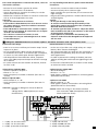
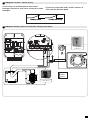
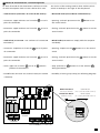
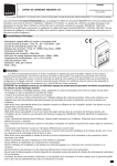
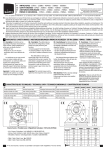
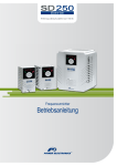
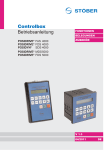
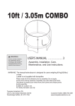
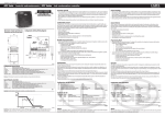
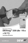
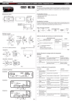
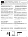
5006253B
F
COFFRET DE COMMANDE SIMUDRIVE 250 - TRIPHASE SANS NEUTRE - 2004460
GB SIMUDRIVE 250 - THREE PHASES CONTROL BOX WITHOUT NEUTRAL - 2004460
Lire attentivement cette notice avant toute utilisation.
Read carefully these instructions before any use.
S.A.S. au capital de 5 000 000 € - Z.I. Les Giranaux - BP71 - 70103 Arc-Les-Gray CEDEX - RCS GRAY B 425 650 090 - SIRET 425 650 090 00011 - n° T.V.A CEE FR 87 425 650 090
i
F- Réservés à l’automatisation des portes industrielles et
commerciales à enroulement vertical, le coffret
SIMUDRIVE 250 est adapté aux moteurs triphasés 400V
dont la puissance n’excède pas 1300 W.
Lisez attentivement le manuel d’instructions qui
accompagne ce coffret de commande. Il fournit d’importantes
indications concernant la sécurité, l’installation, l’utilisation et
l’entretien.Pour les opérations de câblage et d’installation, se
référer aux normes en vigueur. Toutes interventions doivent être
effectuées par du personnel qualifié.
Le SIMUDRIVE 250 est conforme aux directives Européennes
89/336/CEE, 73/23/CEE, 98/37/CEE et modification successives.
Le SIMUDRIVE 250 doit installé avec une porte motorisée
industrielle, commerciale ou de garage selon la norme NF EN
13241-1 et est conforme aux normes NF EN 12453 et EN
12445 seulement si il est configuré en mode motorisé (pression
maintenue). La manœuvre de la porte doit être effectuée par
une personne formée ayant une vue directe sur celle-ci. La
personne manœuvrant la porte ne doit pas se trouver ellemême dans une position dangereuse.
L’organe de manœuvre (inverseur à positions maintenues)
doit être protégé par une clé dans le cas d’un usage par des
personnes formées dans un lieu public (cf EN 12453 §5.5.1
table 1 type 2)
Pour répondre aux normes NF EN 12453 et EN 12445, le
boîtier de commande SIMUDRIVE 250 ne doit pas être
configuré en mode mixte.
1
GB- Intended to automation of industrial and
commercial doors, with vertical movement, the
SIMUDRIVE 250 control box suits to 3 phase
motors 400V whose power does not exceed 1300
W.
Read carefully this instruction sheet supplied with this
control box. It will give you some important information
about the safety, the installation , the use and the
maintenance.
Concerning the wiring and the installation, refer to the
valid norms. All handeling must be done by a skilled
employee.
The SD250 control box is in accordance to the
european regulation 89/336/CEE, 73/23/CEE, 98/37/CEE
and next modifications. The SD250 control box must be
install with a motorized industrial, commercial and garage
door according to NF EN 13241-1 and is conform to NF
EN 12453 et EN 12445 only if the SIMUBOX 250 is set in
motorised mode (maintain pressure) and if the handeling
of the door is done by a skilled employee which see the
movement of the door and not in a dangerous position. In
a public area, the switch (instable) must be protect par a
key and use by skilled person (cf EN 12453 §5.5.1 table 1
type 2).
In order to conform to the norms NF EN 12453 et EN
12445, It’s forbidden to program the SD250 control box
in “MIXTE” configuration.
Caractéristiques - Technical data
- Alimentation triphasée : 400V - 50Hz
- Puissance maximum : 1300W
- Protection par fusibles : 10A T
- Température de fonctionnement : -10T50 (-10°C à +50°C)
- Coffret plastique étanche (5 presse-étoupes montés en position
basse)
- indice de protection IP55.
- Encombrement : 220 x 140 x 70 mm
- Poids : 0,750 Kg
- 3 Phase power supply : 400 V - 50 Hz
- Maxi. Power : 1300W
- Protection by fuses : 10A T
- Running temperature : -10T50 (-10°C to + 50°C)
- Waterproof plastic box (5 cable rubber grommets mounted on
low position)
- Protection index : IP55
- Dimensions : 220 x 140 x 70 mm
- Weight : 0,750 Kg
Mode de fonctionnement : MOTORISE
- Ouverture : appui maintenu sur la touche ou sur le point de
commande.
- Fermeture : appui maintenu sur la touche ou sur le point de
commande.
Motorised mode :
- Opening: maintain pressure on the button or on the control
switch
- Closing: maintain pressure on the button or on the control
switch.
2
Possibilités de câblage - Connection possibility
Inverseur à clef
(extérieur)
Moteur triphasé
230V / 400V
ou
Moteur monophasé
230V
1/4
Pour toute manipulation à l’intérieur du coffret, suivre les
instructions suivantes :
For any handling inside the box, please follow hereafter
instructions :
- Dévisser les 2 vis situées à gauche du coffret
- Dévisser à mi-course les 2 vis de droite
- Ouvrir doucement le couvercle du coffret, les 2 vis de
droite servant de charnière
- Débrancher l’interface de liaison en tenant le connecteur
noir et en tirant légèrement vers vous.
Attention :
- ne pas tirer directement sur la liaison.
- Pour faciliter le branchement, lors de la mise en service
du coffret, enlever le couvercle et utiliser le tournevis
fourni avec le coffret.
- Pour rebrancher le connecteur noir : orienter le repère
blanc placé sur la tranche du connecteur vers le repère
J8 de la carte électronique.
- Si le clavier est connecté à l’envers, la carte
électronique ne sera pas endommagée mais le clavier
ne fonctionnera pas.
- unscrew the 2 screws located on left of the box
- unscrew half way the 2 screws on right
- Open carefully the cap of the box, the 2 screws on the
right as hinges
- Plug out the linking interface : hold the black connector
and pull slightly.
Caution:
- do not pull directly on the linking interface.
- To ease the connection during the assembly of the
control box, remove the cap and use the screwdriver
delivered with the control box.
- To connect again the black connector : adjust the white
mark located on the side of the connector to the mark J8
of the electronic relay board.
- If the keyboard is connected in the bad way, the
electronic card will not be damaged but the keyboard
will not work.
3
Câblage du SIMUDRIVE 250 avec un moteur triphasé - Simudrive connection with a three phases motor
Préconisations de câblage
Recommendations of wiring
- Dans le cas ou vous n’utilisez pas l’entrée “Stop” laissez
le pont 2 en place.
- Les fils vert/jaune des câbles servent uniquement au
raccordement de la terre. Ils ne doivent par conséquent,
en aucun cas, être utilisés pour d’autres applications.
- Afin de préserver l’étanchéité du coffret, ne passez
qu’un seul câble par presse-étoupe et vérifiez le serrage
de ce dernier.
- En cas de mauvais sens de rotation du moteur, inverser
les fils V et W.
- In the case of you don’t use a high safety nor "Stop"
button, don’t remove the bridge 2.
- The wire green/yellow are used only for connection of
the ground. Consequently, they do not have used for
other applications.
- In order to preserve the sealing of the box, pass one
cable by stuffing box and check the tightening of this
piece.
- In the event of bad direction of rotation of the motor,
to reverse the wire V and W.
Alimentation triphasée 400V :
- Vérifier la présence du pont 1
- Phases L1 - L2 - L3
- Terre (vert/jaune) raccordée au domino (livré avec le
coffret).
Moteur triphasé 400V :
- Sortie moteur U - V - W
- Terre (vert/jaune) raccordée au domino (livré avec le
coffret).
3 phases power supply 400V:
- Check the bridge 1
- Phases L1 - L2 - L3
- Earth (green / yellow) connected to a connecting block
(delivered with the box)
3 phases motor 400V:
- Motor output U - V - W
- Earth (green / yellow) connected to connecting block
(delivered with rhe control box).
Attention : Vérifier le câblage au niveau du bornier
moteur.
câblage étoile : 400V triphasé (voir notice
motorisation)
1
L1
L2 L3
L1
L2 L3
Caution: Check the wiring on the motor terminals
Star connection: 400V three-phases (refer to
motor instruction sheet).
U
V
W
U
V
W
2
3 4
1 2 5 6
4 x 1,5mm2
6 x 1,5mm2
2
4 x 1,5mm
moteur/motor
1 - 2 (NF) : fin de course haut.
3 - 4 (NF) : fin de course bas.
5 - 6 (NF) : protection thermique.
1 - 2 (NC): UP end limit
3 - 4 (NC): DOWN end limit
5 - 6 (NC): Thermal probe.
2/4
4
Câblage des sécurités - Safeties wiring
Si vous utilisez un antichute pourvu d’un contact
électrique, le mettre en série avec le contact de la sonde
thermique.
5
If you use a satefy brake with a switch, connect it in
series with the thermical probe.
Câblage de différents points de commande - Wiring control points
I n ve r s e ur à c lé
2 0 0 4 964
N2
M
N1 N2
N1
N1
N2
M
MARRON
N1
NOIR 1
N2
NOIR 2
M
Boîte à bouton tournant
instable 2001558
M
3/4
6
Modes de fonctionnement - Functionning modes
Le choix du mode de fonctionnement s’effectue à l’aide
The choice of the running mode is done with the micro-
du mini-interrupteur situé en haut à droite de la carte.
switch located up on the right of the relay board.
- mode motorisé (conforme à la norme NF EN 13241.1) :
- Motorised mode (in accordance with EN13241.1) :
- Ouverture : appui maintenu sur la touche
- Opening : maintain pressure on the
ou sur le
point de commande.
button or on
the control switch
- Fermeture : appui maintenu sur la touche
ou sur le
- Closing : maintain pressure on the
point de commande.
button or on the
control switch.
- mode mixte (ATTENTION : non conforme à la norme NF
- Mixed mode (CAUTION: no comply with the european
EN 13241.1) :
standards) :
- Ouverture : impulsion sur la touche
ou sur le point
- Opening : impulse on the
de commande.
button or on the control
switch
- Fermeture : appui maintenu sur la touche
ou sur le
- Closing : maintain pressure on the
point de commande.
button or on the
control switch
- Arrêt : appui sur la touche
ou sur le
externe
- Stop : pressure on
pendant le mouvement.
button or on the external
during movement.
- Possibilité de connecter une sécurité haute (voir schéma
- Possibility of wiring a Up safety (see following diagram).
ci-dessous).
MODE MOTORISE
MODE MIXTE
(mode par défaut) (non conforme à EN 13241.1)
MIXED MODE
MOTORIZED MODE
(no comply with EN 13241.1)
(default mode)
DSW1
O
Sortie
moteur
N
DSW2
Alimentation
triphasée
SECURITE HAUTE (NF) - UP SAFETY (NC)
4/4