1
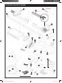
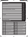
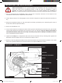
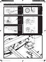
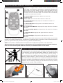
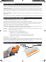
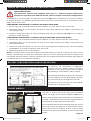
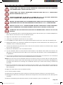
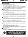
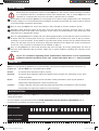
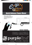
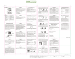
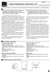
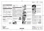
Quick Release Power Mover
Move and rotate
recreational vehicles
with the push of a
button.
PATENT PENDING
USER MANUAL
design...innovate...improve
Purple Line Document Reference EQR130-1305
EQR130 1305 Explorer User Manual vs1.indd 1
7/05/2013 2:34:04 PM
16
3
2
F
PACKAGED CONTENTS IMAGES:
D
4
LYC049-A02
1
2LYC049-B02
3
3
402
C
3
3
123
1
32
1
52
3
2
3
4
项目号
B
热处理
硬 度
表面处理
备注:
A
15
Hrc
未 标 示
1
加工级
棱 边
尖 角
圆 角
-A4
D
C
B
A
Ra
图号
1 LYC050-005
2 LYC050-003
3 LYC050-004
4 LYC050-006
品名
支撑
1
标记 处数 更 改 文 件 号 签字 日 期
材 质
设 计 吴奕仙 标准化
图 纸 标 记
校 对
批 准
审 核
日
期
工 艺
张
52013-1-31 共
16
6
10
7
13
8
9
14
11
12
17
18
22
21
29
14
23
24
27
30
20
19
31
25
26
28
Illustration purposes only
Page 2
EQR130 1305 Explorer User Manual vs1.indd 2
技
7/05/2013 2:34:06 PM
TABLE OF CONTENTS:
Packaged Contents Images
Page 2
Packaged Contents List
Page 3
Introduction
Page 4
Specifications
Page 4
Installation Safety Guidelines
Page 4
Installation Pre-Check Guidelines
Page 5
SeaGo™ Power Mover
Page 5
Mechanical Assembly and Installation - Images
Page 6
Mechanical Assembly and Installation - Instructions
Page 7
Electrical Wiring Diagram
Page 8
Remote Control Handset
Page 9
Pairing the Remote
Page 10
Electronic Control Unit Operation
Page 10
Single Axle and Dual Axle Configurations
Page 11
Battery Configuartion using Four Motors
Page 11
Jockey Wheels
Page 11
Operating Safety Guidelines
Page 12
Operating Instructions
Page 13
Trouble Shooting
Page 14
Maintenance Instructions
Page 15
Warranty
Page 15
Registration
Page 15
Purple Line Address Details
Page 16
PACKAGED CONTENTS LIST:
Item Qty
Description
Item Qty
Description
1
2
Power Movers
19
1
Positive (+) Red Motor Cable 5M
2
2
Quick Release Mount
20
1
Negative (-) Black Motor Cable 5M
3
1
Cross Bar
21
10
Cable Trunking P-Clips 19.2mm
4
2
Chassis Plates
22
10
Cable P-Clips 10.4mm
5
1
Universal Joint
23
2
Battery Terminal Connector 6mm
6
1
19mm Drill Socket
24
4
Battery Terminal Connector 8mm
7
8
Chassis Clamp Bolts M10x55
25
2
Anderson Plug and Socket
8
8
Chassis Nylock Nuts M10
26
6
Cable Spade Connectors
9
8
Washers
27
8
Cable Ties 2x70
10
2
Chassis U-Plate
28
20
11
2
Upper Chassis Clamp Plate
29
1
Isolation Switch and Key
12
2
Lower Chassis Clamp Plate
30
3
Cable Number Tags (1,2,3 & 4)
13
2
Chassis Stop Bolts and Nuts (2 pairs)
31
2
Roller vs Wheel Spacer 20mm
14
1
Engagement Handle
32
3
AAA Batteries (Not Illustrated)
15
1
Electronic Control Unit
33
1
User Manual (Not Illustrated)
16
1
Remote Handset
17
1
Positive (+) Red Battery Cable 1.8M
18
1
Negative (-) Black Battery Cable 1.8M
P-Clip Screws M4x15
Page 3
EQR130 1305 Explorer User Manual vs1.indd 3
7/05/2013 2:34:06 PM
INTRODUCTION:
Thank you for choosing the Purple Line Explorer™ Quick Release Power Mover. The revolutionary Explorer™
Quick Release Power Mover (Patent Pending) is designed to manoeuvre recreational vehicles via a remote
control handset effortlessly, enabling navigation in restricted areas minimising the risk of damage to your
vehicle. It will also aid in hitching and de-hitching the vehicle from the tow vehicle. Explorer™ features
a quick release mount that allows the Power Mover to be swiftly installed and un-installed. When uninstalled you can then and only then undertake river crossings. It can also be removed whilst the vehicle
is under tow to prevent damage to the Power Movers and secure the unit from theft.
Explorer™ has been engineered to the highest standards, manufactured according to the highest quality
assurance processes and is guaranteed for 2 years from date of purchase.
This user manual will enable you to install the Explorer™ and operate it correctly. Accordingly, please read
this manual thoroughly and follow all safety guidelines, prior to installation and usage.
SPECIFICATIONS:
Performance
SGO130
Voltage
12V DC
Average Current Consumption
*25 Ampere
Maximum Current Consumption
*76 Ampere
Maximum Speed
*12cm per second
Weight including all fixture and fittings
*37Kg
Safe Working Load (SWL) Two Motors (Twin Configuration)
2250Kg
Safe Working Load (SWL) Four Motor (Quad Configuration)
3500Kg
Minimum Width (Boat Trailer)
1800mm
Maximum Width (Boat Trailer)
2500mm
Power Source
12V DC
Prefix * indicates an approximation
Average Current Consumption using approximately a 1100Kg loaded single axle boat trailer on a hard level surface.
Maximum Current Consumption using approximately a 1100Kg loaded single axle boat trailer ascending a 1:4 (25%) gradient.
INSTALLATION SAFETY GUIDELINES:
CAUTION
CAUTION
The symbols to the left identify important satefy notices or precautions.
They mean;
Wheel Chock
• CAUTION!
• WARNING!
• SAFETY FIRST!
• IMPORTANT INFORMATION
BEFORE COMMENCING WORK ON THE VEHICLE
READ
the owners manual supplied with the vehicle.
READ
this user manual thoroughly before installation and use, to avoid
personal injury and damage to property.
CHECK
the condition of the chassis and replace any damaged or worn
components.
CHECK
the condition of the tyres and pressure, and if worn replace.
SECURE
all wheels with wheel chocks.
DO NOT
install or operate the unit if you are under the influence of alcohol,
drugs or medication that could impair your ability to use this
equipment.
Worn Tyre
x
Page 4
EQR130 1305 Explorer User Manual vs1.indd 4
7/05/2013 2:34:06 PM
INSTALLATION - PRE CHECK GUIDELINES:
These instructions are of a general guidance as installation will vary according to the
make and model of the recreational vehicle. To aid you with the installation a video is
available for viewing at www.purpleline.com.au. If in doubt regarding the installation of
Explorer™ contact the dealer it was purchased from and seek instruction before proceeding.
1. Prior to commencing the installation clean, and de-rust if required, all areas on the chassis of the
recreational vehicle where components will be afixed.
2. If the chassis requires de-rusting apply an anti-corrosion compound or paint for protection and allow to
dry.
3. Place the recreational vehicle on a dry and hard level surface, preferably over a assembly pit for ease of
access and enhanced personal safety.
4. Ensure the handbrake is on.
5. If you need to raise the recreational vehicle off the ground to aid fitting the Cross Bar use a jack similar
to the Kojack Hydra Jack and follow the instructions in the user manual. It is not safe to work under a
recreational vehicle unless it is correctly secured by Prop-Jacks or Ramps and Wheel Chocks.
Use an appropriate jacking product.
6. Unpack all the Explorer™ components and ensure all are accounted for by checking them against the
Packaged Contents Images and List, as featured on Pages 2 and 3.
7. Record on the the guarantee section at the end of this manual, the serial numbers located on the inside
edge of the gearbox attached to the Power Movers and register Explorer™ online
EXPLORER™ SCHEMATIC:
Motor
Gearbox
Electrical Connection
Roller
Retention Spring
Carrier Body
Spindel
Sliding Bolts and Slots
Tonque
Retaining Pin
Page 5
EQR130 1305 Explorer User Manual vs1.indd 5
7/05/2013 2:34:07 PM
MECHANICAL ASSEMBLY and INSTALLATION DIAGRAMS:
Diagram 1: Explorer in the Disengaged Position
Diagram 1a: Explorer Disengaged from Roller
20mm Gap
20mm Gap
between
roller &
tyre
Silder Bolts
Slots
Diagram 2: Explorer - to Disengaged
Diagram 4: Mounting Explorer
Engagement
Handle
Slot for
tonque
Diagram 3: Assembly Power Movers, Cross Bar and QR Mounts
Tonque
Power Mover
QR Mount
Cross Bar
QR Mount
Power Mover
Diagram 5: Installing Explorer.
Page 6
EQR130 1305 Explorer User Manual vs1.indd 6
7/05/2013 2:34:13 PM
MECHANICAL ASSEMBLY and INSTALLATION INSTRUCTIONS:
The Chassis Plates supplied with Explorer™ are suitable for most recreational vehicles. However
some recreational vehicles require non-standard plates. Check with the dealer to ensure you
have the correct Chassis Plates to fit Explorer™.
1. Prior to commencing assembly, check that Explorer™ is set in the disengaged position. Explorer™ is set
in the disengaged position when the Slider Bolts are positioned to the right of the Slots. Refer Diagrams
1 and 1a.
2. If Explorer™ is set in the engaged position, insert the Handle (Item 14) into the Spindle and rotate
clock-wise. Refer Diagram 2.
3. Take the Quick Release Mounts (Item 2) and the Cross Bar (Item 3) and join together as per Diagram 3.
Loosely tighten the nuts, as you will be required to adjust these later.
4. Clip the Power Movers (Item 1) onto the Quick Release Mounts as per Diagram 4. This can be achieved
by tilting the back of the Power Mover upwards and slotting the tongue on the Carrier Body into the slot
on the Quick Release Mount. Once it is slotted in, lower the rear of the Power Mover. There is no need at
this stage to insert the Retaining Pin.
5. Place the Motor and Cross Bar Assembly, Diagram 3, on a mat and drag under the recreational vehicle
with the Rollers facing the wheels.
6. Raise the Assembly so that the centre axis of the Rollers is equal in height to the centre axis of the
Wheels and rest on a block of wood etc.
7. Tape the 20mm Spacers (item 31) to the Rollers at centre axis point.
8. Then move the assembly so that the Rollers with the Spacers attached are hard against the tyres.
9. Referring to Diagram 5, position one of the Chassis Plates (Item 4 - Left and Right hand version supplied) on the inside of the recreational vehicle’s chassis so it is sitting slightly above the Cross Bar with
the lip facing inward.
10.Mark where the holes on the Chassis Plate marry with the chassis on the recreational vehicle.
11.Remove the Chassis Plate and drill 3 holes sufficient for the three 70mm Bolts (Not supplied) to be inserted.
12.Install the Chassis Plate and tighten the 70mm nuts and bolts.
13.Repeats Steps 9,10, 11 and 12 for the other side ensuring that both Chassis Brackets are in the same
position on each side of the recreational vehicle’s chassis.
14.Loosely fit the Chassis U-Plate (Item 10), the Upper Chassis Clamp Plate (Item 11) and the Lower
Chassis Clamp Plate (Item 12) to the Chassis Plate and Cross Bar with the Bolts, Nuts and Washers
supplied (Items 7, 8 and 9 and 13) as per Diagram 5.
15.Ensure the assembly is aligned on all points as mention previously, all components aligned with the
Chassis on the recreational vehicle, Roller centre axis equal to the centre axis of the Wheel and each
Rollers identically spaced 20mm from the tyre. The Cross Bar can be slid forward and backwards on the
Chassis Clamp Plates.
16.Ensure that each Power Mover is free to move forward and backward and do not obstruct the shock absorbers or any other obstacle that is likely interfere with their operation. Also ensure that the gearbox
on the Power Movers has a minimum distance of 10mm to the inner surface of the tyre when in the
engaged position.
17.Once correctly aligned tighten all Bolts and Nuts (Items 7, 8 and 9) to a torque setting of 55Nm.
18.Check the alignments of all assembled components and if correct tighten the Chassis Stop Bolts and
Nuts (Items 13) to a torque setting of 55Nm. The Chassis Stop Bolts and Nuts grip the lip of the Chassis
Bracket helping prevent the Power Movers from sliding along the chassis.
19.Fit the Retaining Pins to the Power Mover.
EQR130 1305 Explorer User Manual vs1.indd 7
Page 7
7/05/2013 2:34:13 PM
ELECTRICAL WIRING DIAGRAM:
4
3
2
Leads
3&4
1
Anderson Plugs
Leads
1&2
View
when
installed
behind
wheels
Power Movers
Explorer™ is supplied with a Battery Wiring Loom designed to connect the Electronic Control Module,
Isolation Switch and Battery. Additionally, it has a two wiring looms that connect to the Electronic Control
Module, which include an Anderson Plug at the other end to connect to the Anderson Socket on the Power
Movers.
1. Take one of the wiring looms with the Anderson Plug and plug the terminals at the other end into
terminals 1 & 2 on the Control Unit.
2. Feed the lead through the recreational vehicle then Plug the Anderson Plug into the Anderson Socket
of the Power Mover as per the above diagram. Repeat for the other Power Mover and secure both leads
with the P-Clips and Screws supplied,
3. Take the Red Battery Terminal Lead (+) and connect to the Isolation Switch. Then connect the lead
from the Isolation Switch to the positive terminal on the Control Unit and secure the switch and leads.
4. Take the Black Battery Terminal Lead (-) and connect to negative terminal on the Control Unit and
secure the lead.
5. Engage the Power Movers and Explorer™ is now powered and ready to operate.
Ensure to connect all terminals correctly, as cross polarsing them will
short the Electronic Control Unit and void the warranty
Page 8
EQR130 1305 Explorer User Manual vs1.indd 8
7/05/2013 2:34:14 PM
REMOTE CONTROL HANDSET OPERATION:
Explorer™ is supplied with a Remote Control Handset powered by
three ‘AAA’ 1.5V batteries. The Remote is activated by pressing the
Power Button (A) twice within 1 second. Once activated the Green
LED will illuminate and the directional control buttons can now be
accessed to move the Boat Trailer. The Remote will automatically
turn off if not used for 60 seconds.
A - Power Button: press twice within one second to
activate Remote.
Green LED: will illuminate when Remote is switch on.
B - Forward Button: will propel the recreational vehicle in a
forward direction.
C - Reverse Button: will propel the recreational vehicle in a
reverse direction.
D - Forward Left Button: will propel the right wheels in a forward
direction.
E - Forward Right Button: will propel the left wheels in a forward
direction.
F - Reverse Left: will propel the right wheels in a reverse
direction.
G - Reverse Right: will propel the left wheels in a reverse
direction.
To rotate the recreational vehicle on its axis in a clockwork direction press the ‘left forward’ (D) and ‘right
reverse’ (G) buttons simultaneously. To rotate the recreational vehicle on its axis in a anti-clockwork direction
press the ‘right forward’ (E) and ‘left reverse’ (F) buttons simultaneously.
Note: This function is disabled when the Control Unit is configured to operate in twin axle mode.
When pressing a directional button on the Remote, the recreational vehicle will start slowly at
first and reach its full speed within 2.5 seconds, to minimise stress on the trailer.
REMOTE HANDSET BATTERIES:
Turn the Remote over and gently push and slide the battery access panel
in the direction of the arrow head (below diagram A). Insert three new
‘AAA’ 1.5V batteries and replace the battery access panel by sliding it
into the Remote in the opposite direction to open it. When replacing old
batteries, please dispose of these according to guidelines published by
your local authority. Note batteries are considered a hazzardous material.
Check the condition of the batteries regularly to ensure they are in prime
condition and not leaking. Damage to the Remote caused by leaking
batteries is not covered under warranty.
Page 9
EQR130 1305 Explorer User Manual vs1.indd 9
7/05/2013 2:34:16 PM
PAIRING THE REMOTE:
Explorer™ is supplied by the factory with the Remote already paired to operate in single axle mode. Should
you ever need to replace a Remote or set it up to operate in Dual Axle mode, follow these instructions.
SINGLE AXLE MODE: Switch on the Isolation Switch and the Control Unit LED’s will flash for ten seconds.
Using the Aerial press the Rest Button on the Control Unit and the Green LED will flash. Whilst the Green
LED is flashing press the Power Button on the Remote twice. The Green LED on the Control Unit will remain
on.
DUAL AXLE MODE: For Dual Axle configurations repeat the foregoing process with the Remote for both
Control Units.
After completing these procedures the Explorer™ will operate after pressing one of the directional buttons
ELECTRONIC CONTROL UNIT OPERATION:
The Electronic Control Unit controls the motors via the Remote.
The Control Unit has three LED lights (Fig 6) and one recessed button (Fig 6A).
When turning the Isolation Switch on, the Control Unit will perform a self-test automatically. All the LED’s
will illuminate for 0.2 seconds and then cease, which indicates the Control Unit is functioning correctly.
If there is a fault, the Control Unit LED’s will flash accordingly:
Green LED: Will illuminate when the Remote is turned on. If the Remote is out of range the LED will flash.
(Maximum range of signal is 100 metres without obstruction)
Blue LED: Will illuminate when the temperature of the control unit exceeds its operational limit or when
battery voltage is too low or too high.
Red LED:
Will illuminate indicating the following errors;
• Voltage too low <10V: LED will flash twice slowly.
• Voltage too high >15V: LED will flash fast five times.
• Electric current is too high (= or >120A) LED will constantly flash.
• Temperature is too high >80C: LED is will illuminate permanently
Reset Button:Used for pairing the Remote.
The Control unit will automatically turn off if no button on the Remote is pressed within 60 seconds or the
Power Mover is working constantly in one direction for longer than three minutes. This is a built in safety
feature to preserve battery power and prevent the Control Unit from overheating.
ELECTRONIC CONTROL UNIT:
A: Reser Button
Red LED
Blue LED
Green LED
Aerial
Page 10
EQR130 1305 Explorer User Manual vs1.indd 10
7/05/2013 2:34:18 PM
SINGLE AXLE AND DUAL AXLE CONFIGURATIONS:
IMPORTANT NOTICE
The Electronic Control Unit supplied with Explorer™ features Quattro Electronics,
designed to operate in two different modes, either in single or dual axle configurations.
As advised on the previous page, the Electronics Unit with Explorer™ is supplied by the factory to operate
in single axle mode. The following procedures instruct you how to set the Remote up to operate in either
single or dual axle modes.
CONFIGURING THE REMOTE TO OPERATE IN SINGLE AXLE MODE.
1. Remove any one of the AAA batteries from the Remote you have paired to the Control Unit.
2. Hold down button ‘E’ on the Remote and keep it down whilst replacing the battery. The Remote will
sound single beeps.
3. Continue to hold down button ‘E’ until the beeping stops. Once the beeping stops Explorer™ is ready to
operate in single axle mode.
CONFIGURING THE REMOTE TO OPERATE IN QUATTRO MODE (DUAL AXLE MODE)
1. Remove any one of the AAA batteries from the Remote you have paired to the two Control Units.
2. Hold down button ‘G’ on the Remote and keep it down whilst replacing the battery. The Remote will
sound double beeps.
3. Continue to hold down button ‘G’ until you hear a long beep and the beeping stops. Once the beeping
stops Explorer™ is ready to operate in dual axle mode.
4. Repeat these steps for the second Remote.
Note: In dual axle mode you will not be able to hold down Buttons ‘G’ and ‘D’ or buttons ‘E’ and ‘F’ on the
Remote simultaneously to rotate the recreational vehicle on its axis. Pressing these buttons together will
not activate the Power Movers. However, all the buttons on the Remote pressed individually will propel the
recreational vehicle in the directions indicated.
BATTERY CONFIGURATION USING FOUR MOTORS:
To maximise the performance of Explorer™
using four motors a battery output of 100AH is
required. If your current battery does not posses
this capacity a second battery will be needed.
If connecting two batteries together it is important
that each battery has the same capacity and they
are connected as per the diagram to the left.
If unsure on how to connect two 12V batteries
consult with an auto-electrician.
JOCKEY WHEELS:
Single Wheel
Twin Wheel
The type of jockey wheel used with your recreational
vehicle can impact on the manoeuvrability of Explorer™.
Ideally a Jockey Wheel with a 90 degree wheel bracket (as
featured - single wheel) is the most ideal configuration for
a recreational vehicles fitted with single axles.
For recreational vehicles fitted with dual axles the use of a
twin jockey wheel (as featured) is recommended. Single
jockey wheels have a tendency to stick or dig in when
used with four Power Movers fitted, due to the heavy ball
weight.
Page 11
EQR130 1305 Explorer User Manual vs1.indd 11
7/05/2013 2:34:19 PM
OPERATING SAFETY GUIDLINES:
The following safety guidelines will enable you to gain maximum benefit when using Explorer™
and be able to operate safely. Accordingly please note the guideline and warnings.
Before use check that there is no damage to the recreational vehicle or Explorer™ that
could affect its performance.
Before use check that there is no corrosion, dirt or grime that could effect the operation
of Explorer™.
Before use check the battery is fully charged.
Be aware attaching the Power Movers will increase the weight of the recreational vehicle
potentially impacting on the performance of the tow vehicle and available carrying capacity
of the vehicle.
Do not exceed the safe working load of Explorer™.
Ensure that other persons especially children, pets and other obstacles are removed and
kept away from the recreational vehicle whilst it is being manoeuvred.
To maintain signal strength, always ensure that during manoeuvring the distance between
the Remote and Control Unit is within 5 metres.
When manouvering the recreational vehicle ensure you remain close enough to engage
the handbrake at any time in case of mechancial failure, especially on uneven terrain or
gradients.
Do not rely on Explorer™ to act as a brake.
Do not tow or manually manoeuvre the recreational vehicle with the Rollers engaged.
Apply the handbrake after manoeuvring the recreational vehicle.
Ensure either the Power Movers are removed or the Rollers disengaged when not in use.
This will ensure the tyres doe not develop a flat spot and release pressure on the Rollers.
After using Explorer™ turnoff the Isolation Switch.
Do not make any modifications or alterations to Explorer™. This is not only dangerous but
will void the warranty and all liability claims resulting from any modifications made.
REMOVE THE POWER MOVERS
BEFORE ATTEMPTING A RIVER
CROSSING.
FAILURE TO DO THIS WILL DESTROY
THE POWER MOVERS VOIDING YOUR
WARRANTY
Page 12
EQR130 1305 Explorer User Manual vs1.indd 12
7/05/2013 2:34:20 PM
OPERATING INSTRUCTIONS:
PLEASE READ THE MANUFACTURER’S HANDBOOK THOROUGHLY BEFORE OPERATING
THE RECREATIONAL VEHICLE AND EXPLORER™.
PLEASE READ THE SAFETY GUIDELINES SUPPLIED WITH EXPLORER™ THOROUGHLY
BEFORE OPERATING EXPLORER™.
ENSURE THE BATTERY TO BE USED TO POWER EXPLORER™ IS IN GOOD CONDITION,
FULLY CHARGED AND OPERATING WITHIN SAFE GUIDELINES.
ENSURE THE HAND BRAKE ON THE RECREATIONAL VEHICLE IS FULLY ENGAGED AND IT IS
UNHITCHED FROM THE TOW VEHICLE BEFORE FITTING THE EXPLORER™ POWER MOVERS.
REMOVE THE EXPLORER™ POWER MOVERS BEFORE ATTEMPTING A RIVER CROSSING.
NOTE: IMMERSING THE POWER MOVERS IN WATER WILL DESTROY THE MOTORS.
DISENGAGE THE ROLLERS AFTER HITCHING THE RECREATIONAL VEHICLE TO THE TOW
VEHICLE.
1. Park the recreational vehicle in safe and appropriate position that will allow you to install the Explorer™
Power Movers and manoeuvre the recreational vehicle.
2. Apply the hand brake on the recreational vehicle.
3. Unhitch the recreational vehicle from the tow vehicle.
4. Fit the Explorer™ Power Movers to the Quick Release Mounts and secure each with the Retaining Pin.
5. Engage both Rollers, by inserting the Handle into the Spindle on each Power Mover and cranking it anticlockwise until it is locked into position.
6. Connect the Anderson Plug from the Control Unit onto the Anderson Socket on the Power Mover. Repeat
for the other Power Mover.
7. Release the Hand Brake on the recreational vehicle.
8. Turn the Isolation Switch on and press the Power Button on the Remote twice within one second. The
LED light on the Remote and Green LED on the Control Unit will illuminate, which indicating Explorer™
is operational.
9. To move the recreational vehicle press the appropriate directional button on the Remote. The recreational
vehicle will stop as soon as any of the directional buttons are released.
10.Explorer™ will move the recreationbal vehicle at one speed (12cm per second) after an initial soft start.
The speed may increase a little when descending and decrease a little when ascending. Note Explorer™
is slightly more effective at reversing the recreational vehicle up an incline than moving it forward up
an incline.
11.Once the recreational vehicle has been manoeuvred into position, turn off the Remote by pressing the
power button once. The Green LED on the Remote and the Green LED on the Electronic Control Unit will
both extinguish.
12.Apply the hand brake on the recreational vehicle.
13.Turn off the Isolation Switch.
14.Disconnect the Anderson Plug from Control Unit from the Anderson Sockets on the Power Movers.
15.Disengage the Rollers by inserting the Handle into the Spindle on each Power Mover and cranking them
clockwise.
16.Remove the Retaining Pins and Power Movers, for safe storage or prior to crossing a river.
Page 13
EQR130 1305 Explorer User Manual vs1.indd 13
7/05/2013 2:34:21 PM
TROUBLE SHOOTING:
UNIT FAILS TO OPERATE:
Check the Isolation Switch (29) is in the on position.
Check that the batteries have been installed in the remote and that they work. If not install or replace
the three ‘AAA’ batteries. Refer page 10 to install batteries in the remote.
Check that the 12V Battery used to power Explorer™ is fully charged. The Control Unit will indicate if
the charge in the battery is low when the Blue LED is on and the Red LED is flashing twice slowly. If the
charge is low, recharge the battery or if this fails to improve the level of charge in the battery, replace it.
Check the Remote is ‘paired’ with the Control Unit. Refer page 11 to pair the Remote.
BATTERY VOLTAGE:
Automotive batteries are rated at 12V, however a fully charged battery will deliver a charge closer to
13V. A Voltmeter reading of 12.7V or higher indicates that the battery is 100% charged, 12.5V is three
quarters charged and 12.4V can indicate the battery is only 50% charged. SeaGo requires an output
of at least 12.5V to function.
Check the power cable is connected to the battery.
Check the condition of the power cable and terminals. If the cable or terminals are damaged replace
and if the terminals are corroded clean.
Check that the battery is not overloaded. The Control Unit will indicate the battery is overloaded when
the Blue LED is on and the Red LED is flashing continuously. If the Control Unit indicates the battery is
overloaded, firstly check your charger to ensure it is operating correctly. Secondly connect a 12V device
to discharge the battery to the optimum level. If the steps do not rectify the matter replace the battery.
REMOTE CONTROL:
The Remote Control is programmed to operate within a distance of 0-5 metres from the Control Unit.
If their is no signal between the Remote and the Control Unit Explorer™ will not operate even though
the LED on the Remote is illuminated.
UNIT OPERATES INTERMITTENTLY:
Check the points detailed in ‘UNIT FAILS TO OPERATE’ and rectify where necessary.
With the rollers engaged, check how much the voltage drops with a voltmeter when the Remote is
activated. If the voltage immediately drops below 10 volts, recharge of replace the battery.
ROLLERS SLIP ON WHEELS:
Check that the rollers and tyres are clean, especially free of oil and grime. If contaminated clean with
an appropriate cleaner.
Check the tyre pressure on both wheels and where below the recommended pressure inflate. Refer to
the manufacturer’s handbook for the recommended tyre pressure.
Check that the distance between the Roller and first point of contact with the tyre is 20mm on both
sides. If not adjust the distance between the rollers and the tyres as detailed in the Mechanical Assembly
and Installation instructions.
ERROR MESSAGES:
All error messages will reset automatically after 40 seconds. If this does not occur, switch off the
Remote ,then switch off the Isolation Switch for a least 15 seconds. Switch on the Isolation Switch then
switch on the Remote by pressing the power button twice with 1 second.
IF IN DOUBT OR IN THE EVENT THE FOREGOING TROUBLE SHOOTING
INSTRUCTIONS FAIL TO RECTIFY THE ISSUE, CONTACT THE DEALER
EXPLORER™ WAS PURCHASED FROM OR PURPLE LINE.
Page 14
EQR130 1305 Explorer User Manual vs1.indd 14
7/05/2013 2:34:21 PM
MAINTENANCE:
Immersing the components used to mount Explorer™ will result in them becoming corroded.
It is important that the recreational vehicle and components used to mount Explorer™ are
checked on a regular basis and if any corrosion is present this be rectified.
If the battery used to power Explorer™ is not going to be used for long periods and is not charged by
a trickle charger, it is recommended that the battery be disconnected from the Control Unit to prevent
it from becoming completely discharged.
Prior to using the Explorer™ ensure the battery is fully charged to provide maximum power.
Regularly check that the rollers of the drive units are free from corrosion, dirt and grime, or other
containments that could impair their operation. If the rollers are contaminated in way clean them with
a brisk brush or appropriate cleaner.
Prior to engaging Explorer™ (whilst still in the disengaged position) check that the rollers are minimum
of 20mm from the contact point of the tyre. This distance may increase over time as the tyre wears,
resulting in a loss of traction. If the distance is greater than 20mm and the loss of traction becomes an
issue, you will either need to fit new tyres or adjust the distance of the Motor Unit to the contact point
of the tyre. The procedure to do effect this is detailed on page 7.
Prior to using Explorer™ check that all bolts and nuts are tight, all moving parts/joints are free of
corrosion and lubricated and all electric cables are in good condition including the integrity of the
insulation.
If you are uncertain regarding these maintenance instructions or are experiencing
problems with the operation of the unit, contact the dealer Explorer™ was purchased
WARRANTY:
Explorer™ (The Goods) is guaranteed for 2 years from date of purchase and subject to Australian Consumer Law.
Purple Line: Warrants Explorer™ is supplied free of defects.
Refund:
The Goods will be refunded if not fit for purpose.
Replaced:
The Goods will be replaced if defects were apparent upon purchase or a major failure occurs, which cannot be repaired.
Repair:
The Goods will be repaired in the event of failure. Goods presented for repair may be repaired or
replaced with refurbished goods or parts of a similar type.
Contacts:
To make a warranty claim first contact the retailer the Goods were purchased from and if purchased
online Purple Line http://www.purpleline.com.au/contact/php
REGISTRATION:
Please register your purchase of Explorer™ to ensure it is covered for the maximum period possible within
7 days of purchase.
You can register your purchase online at www.purpleline.com.au/product-registration.php or
complete the card below and mail to Purple Line.
Serial Number
+
Date of Purchase
Name of Dealer
Page 15
EQR130 1305 Explorer User Manual vs1.indd 15
7/05/2013 2:34:22 PM
5/238 Governor Road, Braeside, VIC 3195
+61 (3) 9588 2959
[email protected]
www.purpleline.com.au
EQR130 1305 Explorer User Manual vs1.indd 16
7/05/2013 2:34:23 PM