1
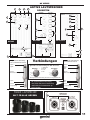
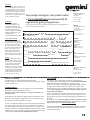
GX SERIES
Professional ABS Moulded Loudspeakers
Professionelle ABS Geformter Lautsprecher
Cajas Acústicas ABS Profesionales
Haut-Parleur Moulé Par ABS Professionnel
GX-800
GX-801
GX-1000
GX-1001
GX-1200
GX-1201
GX-1500
GX-1501
OPERATIONS MANUAL
BEDIENUNGSHANDBUCH
MANUAL DE INSTRUCCIONES
MANUEL D’INSTRUCTIONS
GX SERIES
MULTI LANGUAGE INSTRUCTIONS
ENGLISH.............................................................................PAGE 2
ESPAÑOL............................................................................PAGE 6
DEUTSCH.........................................................................PAGE 10
FRANÇAIS........................................................................PAGE 14
PLEASE READ BEFORE USING APPLIANCE
IMPORTANT WARNING AND SAFETY INSTRUCTIONS!
CAUTION
RISK OF ELECTRIC
SHOCK DO NOT
OPEN!
CAUTION: This product satisfies FCC regulations when shielded cables and connectors are used to connect the unit to other equipment. To prevent electromagnetic interference with electric appliances
such as radios and televisions, use shielded cables and connectors for connections.
The exclamation point within an equilateral triangle is intended to alert the user to the presence of important operating and maintenance (servicing) instructions in the literature accompanying the appliance.
The lightening flash with arrowhead symbol, within an equilateral triangle, is intended to alert the user to the presence of uninsulated “dangerous voltage” within the product’s enclosure that may be of
sufficient magnitude to constitute a risk of electric shock to persons.
READ INSTRUCTIONS: All the safety and operating instructions should be read before the product is operated.
RETAIN INSTRUCTIONS: The safety and operating instructions should be retained for future reference.
HEED WARNINGS: All warnings on the product and in the operating instructions should be adhered to.
FOLLOW INSTRUCTIONS: All operating and use instructions should be followed.
CLEANING: The product should be cleaned only with a polishing cloth or a soft dry cloth. Never clean with furniture wax, benzine, insecticides or other volatile liquids since they may corrode the cabinet.
ATTACHMENTS: Do not use attachments not recommended by the product manufacturer as they may cause hazards.
WATER AND MOISTURE: Do not use this product near water, for example, near a bathtub, wash bowl, kitchen sink, or laundry tub; in a wet basement; or near a swimming pool; and the like.
ACCESSORIES: Do not place this product on an unstable cart, stand, tripod, bracket, or table. The product may fall, causing serious injury to a child or adult, and serious damage to the product. Use only
with a cart, stand, tripod, bracket, or table recommended by the manufacturer, or sold with the product. Any mounting of the product should follow the manufacturer’s instructions, and should use a mounting accessory recommended by the manufacturer.
CART: A product and cart combination should be moved with care. Quick stops, excessive force, and uneven surfaces may cause the product and cart combination to
overturn. See Figure A.
VENTILATION: Slots and openings in the cabinet are provided for ventilation and to ensure reliable operation of the product and to protect it from overheating, and these
openings must not be blocked or covered. The openings should never be blocked by placing the product on a bed, sofa, rug, or other similar surface. This product
should not be placed in a built-in installation such as a bookcase or rack unless proper ventilation is provided or the manufacturer’s instructions have been adhered
to.
POWER SOURCES: This product should be operated only from the type of power source indicated on the marking label. If you are not sure of the type of power supply to your home, consult your product dealer or local power company.
LOCATION: The appliance should be installed in a stable location.
NON-USE PERIODS: The power cord of the appliance should be unplugged from the outlet when left unused for a long period of time.
Fig. A
GROUNDING OR POLARIZATION:
• If this product is equipped with a polarized alternating current line plug (a plug having one blade wider than the other), it will fit into the outlet only one way. This is a safety feature. If you are unable to
insert the plug fully into the outlet, try reversing the plug. If the plug should still fail to fit, contact your electrician to replace your obsolete outlet. Do not defeat the safety purpose of the polarized plug.
• If this product is equipped with a three-wire grounding type plug, a plug having a third (grounding) pin, it will only fit into a grounding type power outlet. This is a safety feature. If you are unable to insert the plug into the outlet, contact your electrician to replace your obsolete outlet. Do not defeat the safety purpose of the grounding type plug.
POWER-CORD PROTECTION: Power-supply cords should be routed so that they are not likely to be walked on or pinched by items placed upon or against them, paying particular attention to cords at
plugs, convenience receptacles, and the point where they exit from the product.
OUTDOOR ANTENNA GROUNDING: If an outside antenna or cable system is connected to the product, be sure the antenna or cable system is grounded so as to provide some protection against voltage surges and built-up static charges. Article 810 of the National Electrical Code, ANSI/NFPA 70, provides information with regard to proper grounding of the mast and supporting structure, grounding
of the lead-in wire to an antenna discharge unit, size of grounding conductors, location of antenna-discharge unit, connection to grounding electrodes, and requirements for the grounding electrode.
See Figure B.
LIGHTNING: For added protection for this product during a lightening storm, or when it is left unattended and unused for long periods of time, unplug it from the wall
outlet and disconnect the antenna or cable system. This will prevent damage to the product due to lightening and power-line surges.
POWER LINES: An outside antenna system should not be located in the vicinity of overhead power lines or other electric light or power circuits, or where it can fall into
such power lines or circuits. When installing an outside antenna system, extreme care should be taken to keep from touching such power lines or circuits as contact with them might be fatal.
OVERLOADING: Do not overload wall outlets, extension cords, or integral convenience receptacles as this can result in a risk of fire or electric shock.
OBJECT AND LIQUID ENTRY: Never push objects of any kind into this product through openings as they may touch dangerous voltage points or short-out parts that
could result in a fire or electric shock. Never spill liquid of any kind on the product.
SERVICING: Do not attempt to service this product yourself as opening or removing covers may expose you to dangerous voltage or other hazards. Refer all servicing
to qualified service personnel.
DAMAGE REQUIRING SERVICE: Unplug this product from the wall outlet and refer servicing to qualified service personnel under the following conditions:
Fig. B
• When the power-supply cord or plug is damaged.
• If liquid has been spilled, or objects have fallen into the product.
• If the product has been exposed to rain or water.
• If the product does not operate normally by following the operating instructions. Adjust only those controls that are covered by the operating instructions as an improper adjustment of other controls
may result in damage and will often require extensive work by a qualified technician to restore the product to its normal operation.
• If the product has been dropped or damaged in any way.
• When the product exhibits a distinct change in performance, this indicates a need for service.
REPLACEMENT PARTS: When replacement parts are required, be sure the service technician has used replacement parts specified by the manufacturer or have the same characteristics as the original
part. Unauthorized substitutions may result in fire, electric shock, or other hazards.
SAFETY CHECK: Upon completion of any service or repairs to this product, ask the service technician to perform safety checks to determine that the product is in proper operating condition.
WALL OR CEILING MOUNTING: The product should not be mounted to a wall or ceiling.
HEAT: The product should be situated away from heat sources such as radiators, heat registers, stoves, or other products (including amplifiers) that produce heat.
2
GX SERIES
7
10
11
8
POWERED SPEAKERS
REAR PANELS
6
3
4
5
3
8
9
7
7
5
6
GX-1001
2
10
6
10
4
GX-801
9
8
3
GX-1201/1501
5
2
2
1
1
1
Unbalanced use of
mono 1/4” jack plugs
Tip
Sleeve
Balanced use with XLR connectors
Input
Sleeve =
Ground/Shield
Strain relief clamp
Balanced use of
stereo 1/4” jack plugs
Connections
Tip =
Signal
1
2
3
6
1 = Ground/ Shield
2= Hot
3= Cold
Output
2
1
3
Tip =
Hot
Ring =
Cold
Sleeve =
Ground/Shield
For unbalanced use, pin 1 and pin 3 have to be bridged
For connections of balanced and
unbalanced plugs, ring and sleeve
have to bridged at the stereo plug
PASSIVE SPEAKERS
SAME FOR ALL SIZES
Tip
Ring
Sleeve
Strain relief clamp
12
3
GX SERIES
INTRODUCTION
Congratulations on your purchase of a Gemini GX Series loudspeaker. Your product is backed by a 1 year limited warranty. With proper care and
maintenance your speaker will provide you with years of reliable service. Please register your product online at WWW.GEMNIDJ.COM or by using
the included form at the end of this manual.
CAUTIONS:
1. All operating instructions should be read before using this equipment.
2. To reduce the risk of electrical shock , do not open the unit .
there are NO USER OR SERVICABLE PARTS INSIDE please refer
servicing to a qualified Gemini Sound Products service technician.
In the USA: If you experiance
problems with this unit, please call
1(732) 346 0061 for Gemni Customer
Service. Do not attempt to return this
equipment to your dealer
CONTROL ELEMENTS
(POWERED SPEAKERS)
1
2
3
4
5
6
7
8
9
FUSE HOLDER/VOLTAGE SELECTOR and MAIN POWER CONNECTOR. Please make sure that your local
voltage matches the voltage indicated on the unit, before you attempt to connect and operate your GX SERIES
loudspeaker. Blown fuses may only be replaced by fuses of the same type and rating.
Use the POWER switch to put your GX SERIES loudspeaker into operation.
MAIN INPUT. These XLR connectors (GX-801 and 1001) and XLR, 1/4” and RCA connectors (GX-1201 and
1501) are the inputs for the signal source. The GX-801 allows you to choose what input type the XLR will be,
simply by using Switch 11 you can choose weather the XLR input is a LINE level input or a MICROPHONE
input. The GX-1001 has separate XLR inputs for MIC and LINE and are adjustable individually. The GX-1201
and 1501 as well as having individual balanced XLR inputs for both MIC and LINE they also have UNBALANCED 1/4” input for MIC and UNBALANCED RCA inputs for LINE level input.
AUX INPUT The GX-801 has an UNBALANCED RCA AUX INPUT and the volume is controlled by the master
volume. The GX-1001/1201 and 1501) have both BALANCED (XLR) and UNBALANCED (RCA) and allow
you to connect an auxiliary input source, if both MAIN INPUT and AUX INPUT are connected simultaneously
both inputs will be heard.
LINE OUTPUT is directly connected to the input and or inputs of the GX SERIES loudspeaker and provides a
one-to-one copy of the input signal, for example, to loop the input through to the input of another device
(e.g. a second GX SERIES loudspeaker).
POWER and CLIP LED The POWER LED will illuminate when the system is in operation. The CLIP LED will
illuminate when the system is overloading, running your GX SERIES loudspeaker at CLIP levels is not recommended and will cause the internal amplifier to fail and or the MAIN POWER FUSE to blow.
The VOLUME level governs the overall volume level of you GX SERIES loudspeaker.
The MIC GAIN/LEVEL rotary governs the GAIN (GX-801) and or LEVEL (GX-1001,1201 and 1501) of the
MICROPHONE INPUT.
The LINE LEVEL rotary adjust the volume of the INPUT and AUX INPUT Channels (GX-1001,1201 and 1501).
TONE/EQ (BASS and TREBLE) CONTROLS TONE (GX-801) will adjust the overall treble output of the
10 GX-801 by turning to the left you will hear less high end frequencies and by turning the rotary to the right you
will hear more high end frequencies.
EQ (BASS and TREBLE) (GX-1001,1201 and 1501) The (TREBLE) rotary will adjust the high end frequencies
and the (BASS) rotary will adjust the low end frequencies of the overall output of the GX SERIES loudspeaker.
11 MIC/LINE SWITCH (GX-801 only) you can choose weather the XLR input of the GX-801 will be a LINE LEVEL
input or a MICROPHONE input. NOTE: USING THIS INPUT WITH A LINE LEVEL SOURCE WHILE
SWITCHED TO THE MIC POSITION MAY CAUSE THE SPEAKER TO OVERLOAD!.
12
(PASSIVE SPEAKERS)
For the GX-800, 1000, 1200 and 1500 use a SPEAKON™ cable from your amplifiers speaker output to the
SPEAKON™ input jack.
4
GX SERIES
SPEAKER STANDS
MOUNTING
TOP VIEW
(GX-1200/1201/1500/1501)
UNDERSIDE B
D
D
C
A
C
A
STAND MOUNTING Insert a stand into the STAND MOUNTING SOCKET
C
STACKING You can also stack the GX SERIES speakers by placing the
RUBBER FEET into the STACKING GROOVES.
B
D
LOCKING PIN You can lock the stand in its socket by inserting the LOCKING
PIN after you have mounted the stand securely
SPEAKER RIGGING mounting hardware should be used to hang the speaker
where appropriate. Speaker stands and mounting hardware are available
separately.
SPECIFICATIONS
CHAIN LINK SETUP
MAIN SPEAKERS
DJ BOOTH
DANCEFLOOR
CHAIN LINKED SPEAKERS
All GX Speakers Have the Following: Steel / Aluminum-Cast Woofer, Stand
Mounting Socket,Auxiliary Line Outputs,/Full Metal Grill, High Temp Voice
Coil,Rigging Points, Rubber Feet, Stacking Grooves, Easy Carry Handles
Shipping Weight: GX-800/801 (27.5 lbs, 12.5 kgs / 31lbs 14.5 kgs)
GX-1000/1001 (35.2 lbs, 16 kgs / 43 lbs, 19.5 kgs)
GX-1200/1201 (48.4 lbs, 22 kgs / 55 lbs, 25 kgs)
GX-1500/1501 (57.2 lbs, 26 kgs / 64.9 lbs, 29.5 kgs)
Specifications subject to change without notice for improvement
Woofer magnet wieght
Woofer voice coil
Woofer impedance
Woofer RMS wattage
Woofer peak wattage
Compression driver magnet wieght
Compression driver diaphram size
Compression driver RMS wattage
Compression driver peak wattage
Crossover specification
Nominal horn dispersion
Sensitivity
Frequency response
Type of amplifier
Total RMS wattage
Total peak wattage
Stand mount hole
GX-800/801
40oz
2” / 50.8mm
8/4 Ohms
70 Watts
150 Watts
13oz
1.35” / 35mm
30 Watts
100 Watts
3.5 Khz,12dB/Oct
30°x 60°
97 dB/1m/1w
70-20 Khz
Mono-Power Amp
100 Watts
250 Watts
35mm
GX-1200/1201
65oz
2.5” / 65mm
8/4 Ohms
150 Watts
400 Watts
13oz
1.35” / 35mm
100 Watts
200 Watts
2.5 Khz,12dB/Oct
30°x 60°
97 dB/1m/1w
45-20 Khz
Mono-Power Amp
250 Watts
600 Watts
35mm
GX-1000/1001
40oz
2” / 50.8mm
8/4 Ohms
120 Watts
250 Watts
13oz
1.35” / 35mm
60 Watts
150 Watts
2.8 Khz,12dB/Oct
30°x 60°
97 dB/1m/1w
60-20 Khz
Mono-Power Amp
180 Watts
400 Watts
35mm
GX-1500/1501
65oz
3” / 72mm
8/4 Ohms
180 Watts
550 Watts
20oz
1.75”/44mm
120 Watts
250 Watts
2.2 Khz,12dB/Oct
30°x 60°
99 dB/1m/1w
45-20 Khz
Mono-Power Amp
300 Watts
800 Watts
35mm
5
GX SERIES
MULTI LANGUAGE INSTRUCTIONS
ENGLISH.............................................................................PAGE 2
ESPAÑOL............................................................................PAGE 6
DEUTSCH.........................................................................PAGE 10
FRANÇAIS........................................................................PAGE 14
POR FAVOR LEA ANTES DE UTILIZAR, INSTRUCCIONES
IMPORTANTES DE SEGURIDAD
CAUTION
RIESGO DE SHOCK
ELECTRICO - NO
ABRIR!
ATENCIÓN: Este producto cumple con la normativa legal si se utilizan cables y conectores blindados para conectar la unidad a otro equipo. Para evitar interferencias electromagnéticas con otros aparatos
eléctricos, como radios y televisores, deben emplearse cables y conectores blindados.
Los signos de exclamación dentro de un triángulo que puedan aparecer en la documentación que acompaña a la unidad pretenden alertar al usuario de instrucciones de operación o mantenimiento importantes.
El signo de un rayo dentro de un triángulo pretende alertar al usuario de la presencia de "voltaje peligroso" no aislado en el inte-rior de la unidad, que podría ser de suficiente intensidad como para constituir riesgo de descarga eléctrica.
LEA LAS INSTRUCCIONES: Deben leerse todas las indicaciones de uso y seguridad antes de usar este producto.
CONSERVE LAS INSTRUCCIONES: Las instrucciones de uso y seguridad deben conservarse para referencias futuras.
ATIENDA A LAS ADVERTENCIAS: Deben seguirse todas las advertencias sobre este producto que figuran en el manual de instrucciones.
SIGA LAS INSTRUCCIONES: Deben seguirse todas las instrucciones del manual.
LIMPIEZA: Este producto debe limpiarse con una mopa suave o con un paño seco. Nunca utilice cera para muebles, gasolina, insecticidas u otros líquidos volátiles, ya que podrían corroer la carcasa.
COMPLEMENTOS: No utilice accesorios que no estén recomendados por el fabricante, pues podrían dañar la unidad.
AGUA Y HUMEDAD: No use este producto cerca de medios acuáticos, como una bañera, un cubo de agua, un fregadero o un lavadero; tampoco en un sótano húmedo, ni cerca de una piscina o similar.
ACCESORIOS: No coloque el producto sobre un carrito, soporte, trípode, brazo o mesa. Podría caer y causar graves daños a un niño o adulto, así como a la propia unidad. Úsese sólo con un carrito,
soporte, trípode, brazo o mesa recomendado por el fabricante. Al montar la unidad deben seguirse siempre las instrucciones y emplearse accesorios recomendados por el fabricante.
CARRITO: Si el producto va sobre un carrito, debe moverse el conjunto con cuidado. Detenciones bruscas, una fuerza excesiva o superficies inadecuadas pueden provocar la caída de todo el conjunto. Véase Figura A.
VENTILACIÓN: Las aperturas y ranuras de la carcasa están diseñadas para la ventilación, aseguran un manejo fiable y lo protegen de cualquier sobrecalentamiento, por tanto, nunca deben cubrirse ni bloquearse. Estas aperturas no deben taparse colocando el producto sobre un sofá, una cama, una alfombra o superficies similares. Nunca debe colocarse en una estructura prefabricada, como una caja o un rack, a menos que tengan la ventilación adecuada o lo permitan las
instrucciones del fabricante.
FUENTES DE ALIMENTACIÓN: Esta unidad debe utilizarse exclusivamente con el tipo de suministro eléctrico indicado en la etiqueta correspondiente. Consúltelo
antes de enchufar el producto si no está seguro del tipo de suministro del lugar donde lo va a usar.
UBICACIÓN: Este aparato debe colocarse en una ubicación estable.
PERIODOS SIN USARLO: Si no se va a usar la unidad durante un tiempo prolongado, desenchúfelo de la corriente eléctrica.
TOMA DE TIERRA O POLARIZACIÓN:
- Si este producto lleva una clavija de corriente alterna polarizada (con un pivote más grueso que otro, tipo inglés), sólo entrará en una posición. Es una medida de
seguridad. Si no puede introducir la cla-vija en el enchufe, gírela. En ningún caso debe forzarse. Si sigue sin entrar, un electricista debería cambiar el enchufe.
Fig. A
- Si la unidad lleva una clavija con tres pivotes (el tercero corres-ponde a la toma de tierra), sólo entrará en un tipo de enchufe. Se trata de una medida de seguridad. Si el enchufe y la clavija no son
compatibles, un electricista deberá cambiar el enchufe. En ningún caso deberá forzarse.
PROTECCIÓN DEL CABLE DE CORRIENTE: Los cables de corriente deben protegerse para que nadie los pise ni corran el riesgo de pinzarse por elementos colocados encima o que los aprisionen.
Debe prestarse especial atención al cable, al enchufe, a los extensores de cable y al punto por donde el cable sale de la unidad.
TIERRA DE LA ANTENA EXTERIOR: Si el producto lleva conectada una antena exterior o sistema de cables, asegúrese de que cuenta con la toma de tierra correspondiente, a fin de proteger la
unidad de variaciones de voltaje y cargas de electricidad estática. Existe documentación oficial acerca de la correcta utilización de la toma de tierra y de las medidas de seguridad pertinentes, conexión
de los electrodos de descarga y sus requisitos. Véase Figura B.
RAYOS: Como protección adicional del producto durante una tormenta eléctrica, o durante periodos prolongados sin usarlo, desenchúfelo de la corriente y desconecte la antena o sistema de cables.
De este modo se protegerá el producto de los daños que pueda producir la caída de un rayo o las fluctuaciones de la red eléctrica.
LÍNEAS ELÉCTRICAS: Nunca debe situarse un sistema de antena cerca de líneas eléctricas u otros circuitos de corriente. Tampoco debe colocarse en lugares donde pueda caer sobre dichos circuitos
eléctricos. Al instalar un sistema de antenización exterior, debe tomarse la extrema precaución de no tocar dichas líneas eléctricas, pues el mas minimo contacto puede ser fatal.
SOBRECARGA: No sobrecargue los enchufes de la pared con ladrones o instalando enchufes múltiples, pues correría el riesgo de electrocución o incendio.
ENTRADA DE OBJETOS O LÍQUIDOS: Nunca introduzca objetos de ningún tipo en el interior del producto, pues podrían tocar una parte eléctrica y cortocircuitar el aparato, lo que resultaría en un incendio o descarga eléctrica. No verter nunca ningún líquido sobre el producto.
REPARACIÓN: No intente reparar el producto por cuenta propia, ya que abrir o retirar la carcasa le expondría a un voltaje peligroso u otros peligros. Diríjase siempre a un centro de servicio técnico autorizado.
DAÑOS QUE REQUIEREN REPARACIÓN: Desenchufe el aparato de la corriente y diríjase a un servicio técnico autorizado si se da alguna de las siguientes situaciones:
- El cable de alimentación o la clavija están dañados.
- Se ha vertido líquido o ha caído algún objeto sobre la unidad.
- El aparato se ha expuesto a la lluvia o a salpicaduras.
- La unidad se ha caído al suelo o dañado de algún modo.
- El aparato no funciona con normalidad, ni aun siguiendo las instrucciones. Ajuste sólo los mandos que se indican en las instrucciones, ja que la manipulación inadecuada de otros controles podría dañar la unidad y requeriría un mayor trabajo de un técnico para restablecer su funcionamiento normal.
- Si el producto muestra anomalías en su funcionamiento, necesita revisión por parte de un servicio técnico autorizado.
Fig. B
RECAMBIOS: Cuando se necesite alguna pieza de recambio, asegúrese de que el servicio técnico utilice piezas originales autori-zadas o que tengan las mismas características que las originales. Los
reemplazos no autorizados pueden causar descargas eléctricas, incendios u otros daños.
COMPROBACIÓN DE SEGURIDAD: Tras la reparación, solicite al técnico que efectúe las comprobaciones de seguridad necesarias para determinar que el producto se encuentra en las condiciones
adecuadas para su funcionamiento.
MONTAJE EN UNA PARED O TECHO: Este producto nunca debe montarse en una pared o en el techo.
CALOR: Este producto debe alejarse de fuentes de calor, como radiadores, estufas u otros aparatos que irradien calor, incluyendo amplificadores.
6
GX SERIES
7
10
11
8
ALTAVOCES AUTOAMPLIFICADOS
PANEL TRASERO
6
3
4
5
3
8
9
7
7
5
6
GX-1001
2
10
6
10
4
GX-801
9
8
3
GX-1201/1501
5
2
2
1
1
1
No balanceado con
jack mono 1/4” jack
Cuerpo =
Masa/Tierra
Balanceado usando jack
estéreo 1/4”
Conexiones
Punta =
Señal
Balanceado con conector XLR
Entrada
1
2
6
1 = Masa/ Tierra
2= Vivo
3= Retorno
Salida
1
3
3
2
Punta =
Vivo
Anillo =
Retorno
Cuerpo =
Tierra/Masa
Para no balanceado, el pin 1 y pin 3 deben puentearse
Punta
Cuerpo
Pestaña de sujección
En conexiones no balanceadas en
conectores estéreo, el anillo y el
cuerpo deben puentearse
IGUAL TODOS TAMAÑOS
PASSIVE SPEAKERS
Punta
Anillo
Cuerpo
Pestaña de sujección
12
7
GX SERIES
INTRODUCTION
Felicidades por la compra de sus cajas acústicas Gemini GX Series. Su producto está amparado por 1 año de garantía limitada. Con el uso y
mantenimiento adecuado sus altavoces le drán años de servicio. Por favor regristre su producto online en WWW.GEMNIDJ.COM o usando el formulario del final de este manual.
CAUTIONS:
1. Todas las instrucciones deben ser leidas antes de usar este aparato
2. Para reducir riesgo de shock electrico, no abra la unidad.
NO HAY PIEZAS REEMPLAZABLES EN EL INTERIOR por favor
consulte al servicio técnico oficial en caso necesario.
En USA: si tiene algún problema con esta unidad, por favor llame al
1(732) 346 0061.(Atención al Cliente).
No intente devolver este aparato a
su distribuidor.
CONTROL ELEMENTS
(POWERED SPEAKERS)
1
2
3
4
5
6
7
8
9
FUSIBLE/SELECTOR DE VOLTAJE y CONECTOR DE ALIMENTACION. Por favor asegurese que la tensión
de su zona es la indicada en la unidad antes de conectar y operar con su caja GX SERIES. Los fusible quemados deben reemplazarse siempre con fusibles del mismo tipo y valor.
Use el interruptor de ENCENDIDO para iniciar la operativa de su GX SERIES.
ENTRADA PRINCIPAL. Estos conectores XLR en (GX-801 y 1001) y XLR, jack 1/4” y RCA en (GX-1201 y
1501) son las entradas de señal de audio. El GX-801 permite elegir que tipo de entrada será el XLR , simplemente con el Switch 11 puede elegir si el XLR es de nivel LINEA o entrada de MICROFONO. El GX-1001
tiene entradas XLR separadas para MICRO y LINEA y se ajustan individualmente. El GX-1201 y 1501 que
también tienen entrada individual balanceada XLR para MICRO y LINEA también tienen entrada NO BALANCEADA JACK 1/4” para MICRO y NO BALANCEADA RCA para entradas de nivel LINEA.
ENTRADA AUX Estos conectores NO BALANCEADOS JACK 1/4” para (GX-801 y 1001) y tipo RCA para
(GX-1201 y 1501) permiten conectar una entrada auxiliar, si ambas ENTRADA PRINCIPAL y ENTRADA AUX
están conectadas a la vez, se oirán ambas por el equipo.
SALIDA DE LINEA está conectada directamente a la entrada o entradas de la GX SERIES y nos ofrece una
copia exacta de la señal de entrada, por ejemplo, para linkear la señal de entrada hacia otra unidad
(por ejemplo a una segunda caja acústica GX SERIES).
LED ALIMENTACION Y CLIP El LED DE ALIMENTACION se enciende cuando el sistema está operativo.El
LED CLIP se enciende cuando el sistema está en sobrecarga, llevar las cajas GX SERIES a nivel de CLIP no
está recomendado ya que podría dañar el amplificador interno o quemar el FUSIBLE DE ALIMENTACION.
El nivel de VOLUMEN controla el volumen general de sus GX SERIES.
El rotativo MIC GANANCIA/NIVEL controla la GANANCIA (GX-801) y/o NIVEL (GX-1001,1201 y 1501) de la
entrada de MICROFONO.
El ajuste rotativo de LINEA controla el volumen de la ENTRADA y ENTRADA AUX (GX-1001,1201 y 1501).
TONO/EQ (GRAVE y AGUDO) (GX-801) ajusta el nivel de agudos de la GX-801 girando a la izquierda oirá
10 menos frecuencias altas y girando hacia la derecha oirá más frecuencias agudas.
EQ (GRAVES y AGUDOS) (GX-1001,1201 y 1501) El rotativo (AGUDOS) ajusta el nivel de frecuencias altas y
el rotativo (GRAVES) ajusta el nivel de frecuencias bajas de la salida total de sus cajas GX SERIES.
11
MICRO/LINEA (GX-801 solo) usted puede elegir si la entrada XLR de su GX-801 será de un nivel LINEA o
nivel MICROFONO. NOTA: USANDO ESTA ENTRADA CON UN DISPOSITIVO DE LINEA CUANDO ESTA
SELECCIONADO MICRO, PUEDE CAUSAR SOBRECARGA Y DISTORSION EN SUS ALTAVOCES!.
12
Para GX-800, 1000, 1200 y 1500 use cable SPEAKON™ desde la salida de altavoces de su amplificador hasta
la entrada SPEAKON™ de sus altavoces.
(PASSIVE SPEAKERS)
8
GX SERIES
SPEAKER STANDS
MOUNTING
TOP VIEW
(GX-1200/1201/1500/1501)
UNDERSIDE B
D
D
C
C
A
PIES DE BAFLE Inserte un soporte en el ALOJAMIENTO DE PIES BAFLE
C
APILAR Usted puede tambien poner sus GX SERIES una sobre otra colocando los PIES DE GOMA en los AGUJEROS DE APILAR.
B
D
PIN DE SEGURIDAD Usted puede fijar sus pies de bafle en el alojamiento usando un PIN DE SEGURIDAD
RIGGING se puede utilizar hardware de montaje para colgar estos altavoces
con el apropiado material de anclaje (no incluido) de venta separada.
SPECIFICATIONS
CHAIN LINK SETUP
ALTAVOCES PRINCIPALES
CABINA DJ
PISTA DE BAILE
ALTAVOCES LINKEADOS
Todos los altavoces GX tienen lo siguiente: Woofer de aluminio y acero, alojamiento de pie de bafle, salidas Aux y linea,/Rejilla entera metálica, Bobina de
alta temperatura, puntos de anclaje, patas de goma, agujeros de apile, asas
Peso de envio:
A
GX-800/801 (27.5 lbs, 12.5 kgs / 31lbs 14.5 kgs)
GX-1000/1001 (35.2 lbs, 16 kgs / 43 lbs, 19.5 kgs)
GX-1200/1201 (48.4 lbs, 22 kgs / 55 lbs, 25 kgs)
GX-1500/1501 (57.2 lbs, 26 kgs / 64.9 lbs, 29.5 kgs)
Especificaciones sujetas a cambio sin previo aviso por mejoras
Woofer peso del iman
Woofer bobina
Woofer impedancia
Woofer potencia RMS
Woofer potencia de pico
Compresión driver peso del iman
Compresión driver diafragma
Compresión driver potencia RMS
Compresión driver potencia de pico
Crossover especificaciones
Dispersión nominal de la bocina
Sensibilidad
Respuesta en frecuencia
Tipo de amplificador
Total potencia RMS
Total potencia de pico
Alojamiento de pie de bafle
GX-800/801
40oz
2” / 50.8mm
8/4 Ohms
70 Watts
150 Watts
13oz
1.35” / 35mm
30 Watts
100 Watts
3.5 Khz,12dB/Oct
30°x 60°
97 dB/1m/1w
70-20 Khz
Mono-Power Amp
100 Watts
250 Watts
35mm
GX-1200/1201
65oz
2.5” / 65mm
8/4 Ohms
150 Watts
400 Watts
13oz
1.35” / 35mm
100 Watts
200 Watts
2.5 Khz,12dB/Oct
30°x 60°
97 dB/1m/1w
45-20 Khz
Mono-Power Amp
250 Watts
600 Watts
35mm
GX-1000/1001
40oz
2” / 50.8mm
8/4 Ohms
120 Watts
250 Watts
13oz
1.35” / 35mm
60 Watts
150 Watts
2.8 Khz,12dB/Oct
30°x 60°
97 dB/1m/1w
60-20 Khz
Mono-Power Amp
180 Watts
400 Watts
35mm
GX-1500/1501
65oz
3” / 72mm
8/4 Ohms
180 Watts
550 Watts
20oz
1.75”/44mm
120 Watts
250 Watts
2.2 Khz,12dB/Oct
30°x 60°
99 dB/1m/1w
45-20 Khz
Mono-Power Amp
300 Watts
800 Watts
35mm
9
GX SERIES
MEHRSPRACHIGE ANLEITUNG
ENGLISH............................................................................SEITE 2
ESPAÑOL...........................................................................SEITE 6
DEUTSCH........................................................................SEITE 10
FRANÇAIS........................................................................SEITE 14
VOR BENUTZUNG DES GERÄTS LESEN. WICHTIGE
HINWEISE&SICHERHEITSBESTIMMUNGEN
ACHTUNG
NICHT ÖFFNEN,
STROMSCHLAGGEFAHR!
VORSICHT: Dieses Produkt erfüllt die FCC-Regeln, wenn Sie zum Anschluss abgeschirmte Kabel und Stecker verwenden, um es mit anderen Geräten zu verbinden. Auch um elektromagnetische Störungen anderer elektrischer Geräte wie Radios oder Fernseher zu vermeiden, benutzen Sie abgeschirmte Kabel und Stecker für
die Verbindungen.
Das Ausrufezeichen im gleichseitigen Dreieck weißt Sie in der Bedienungsanleitung auf wichtige Bedienungsanweisungen und Wartungs-/Serviceanweisungen hin.
Das Blitzsymbol im gleichseitigen Dreieck dient dazu, den Benutzer vor gefährlichen Spannungen an nicht isolierten Stellen im Gehäuse zu warnen, die so groß sind, dass sie eine Gefahr für den Benutzer darstellen.
ANWEISUNGEN LESEN: Lesen Sie alle Sicherheits- und Bedienungsanweisungen, bevor Sie mit dem Produkt arbeiten.
AUFBEWAHRUNGSHINWEIS: Bewahren Sie alle Sicherheits- und Bedienungsanweisungen gut auf.
WARNHINWEISE: Alle Warnhinweise für das Produkt und die Bedienungsanweisungen müssen genau eingehalten werden.
ANWEISUNGEN BEFOLGEN: Alle Anweisungen zum Betrieb des Produkts sollten befolgt werden.
REINIGUNG: Das Produkt sollte nur mit einem Polier- oder einem weichen trockenen Tuch gereinigt werden. Benutzen Sie dazu niemals Möbelwachs, Benzine, Insektenmittel oder andere flüchtige Reinigungsmittel, denn Sie könnten zur Korrosion des Gehäuses führen.
ERWEITERUNGEN: Benutzen Sie keine Erweiterungen, die nicht vom Hersteller empfohlen sind, da sie zu Risiken führen könnten.
WASSER&FEUCHTIGKEIT: Benutzen Sie dieses Produkt nicht in der Nähe von Wasser, z. B. in der Nähe einer Badewanne, einer Waschschüssel, eines Küchenspülbeckens, eines Waschbeckens, in einem feuchten Keller, in der Nähe eines Schwimmbeckens oder an ähnlichen Orten.
ZUBEHÖR: Stellen Sie das Produkt nicht auf eine wackelige oder labile Unterlage. Das Produkt könnte herunterfallen und dabei Kinder oder Erwachsene verletzen, wie auch selber beschädigt werden. Stellen Sie das Produkt nur auf vom Hersteller empfohlene oder verkaufte Unterlagen. Jede Befestigung und Montage
des Produkts sollte nach den Anweisungen des Herstellers ausgeführt werden. Nutzen Sie dazu ein vom Hersteller empfohlenes Montageset.
MOBILE UNTERLAGEN: Bewegen Sie eine Kombination aus dem Produkt und einer mobilen Unterlage mit Vorsicht. Schnelles Anhalten, zu viel Schub oder unebene Böden können dazu führen, dass sich Produkt und mobile Unterlage überschlagen (SIEHE FIG. A).
BELÜFTUNG: Schlitze und Öffnungen im Gehäuse sind für die Belüftung vorgesehen. Sie stellen den zuverlässigen Betrieb des Produkts sicher und schützen es vor Überhitzung. Diese Öffnungen dürfen nicht verschlossen, blockiert oder bedeckt werden.Stellen Sie
deswegen das Produkt niemals auf ein Bett, ein Sofa, einen Teppich oder Stellen mit ähnlicher Oberfläche. Wenn Sie dieses Produkt in einer festen Installation wie z. B. in einem Regal oder einem Rack einbauen, sorgen Sie für ausreichende Belüftung oder
sorgen Sie dafür, dass die Bestimmungen des Herstellers genau ein gehalten werden.
STROMANSCHLUSS: Dieses Produkt darf nur mit dem auf dem Gerät angegebenen Strom betrieben werden. Wenn Sie sich nicht sicher sind, welche Stromart Sie bei sich zu Hause haben, fragen Sie den Verkäufer des Geräts oder Ihren Stromversorger.
AUFSTELLUNGSORT: Stellen Sie das Gerät an einem festen Ort auf.
ZEITEN DES NICHTGEBRAUCHS: Ziehen Sie das Stromkabel aus dem Gerät heraus, wenn Sie es für eine längere Zeit nicht gebrauchen.
ERDUNG ODER POLUNG: Wenn dieses Produkt mit einem gepolten Wechselstromstecker (ein Stecker mit einem Kontakt mehr als andere Stecker) ausgestattet ist, passt dieser nur in einer bestimmten Richtung in die Steckdose und ist ein besonderes Sicherheitsmerkmal. Sollten Sie den Stecker nicht komplett in die Steckdose stecken können, versuchen Sie ihn andersherum einzustecken. Sollte der Stecker auch dann noch nicht in die Steckdose passen, beauftragen Sie einen Elektriker, um diese veraltete Steckdose auszutauschen.
Fig. A
Wenn dieses Produkt mit einem geerdeten dreipoligen Stecker ausgestattet ist, hat der Stecker einen dritten (Erdungs-)Kontakt und passt nur in eine Steckdose mit entsprechender Erdung. Auch das ist ein Sicherheitsmerkmal. Sollte der Stecker nicht in die Steckdose passen, beauftragen Sie einen Elektriker, um diese veraltete Steckdose auszutauschen.
SCHUTZ DES STROMKABELS: Stromkabel sollten so verlegt werden, dass man nicht auf sie treten kann, noch dass sie von darauf stehenden oder gegen sie stoßenden Gegenständen gequetscht werden. Achten Sie besonders auf Kanten, Sicherung, Stecker und Buchsen.
AUSSENANTENNENERDUNG: Wenn Sie eine Außenantenne oder ein Radio-/Fernsehkabelsignal an das Produkt anschließen, achten Sie darauf, dass die Antenne oder das Kabel geerdet sind, um dafür zu sorgen, dass Überspannungen und elektrostatische Aufladungen nicht auftreten können. Im Artikel 810 des National Electrical Code, ANSI/NFPA 70, finden Sie Informationen über die richtige Erdung des Antennenmasts und weitere Informationen zu diesem Thema. (SIEHE AUCH FIG. B).
GEWITTER: Trennen Sie das Produkt während eines Gewitters oder wenn es unbeaufsichtigt ist oder wenn es für eine lange Zeit nicht benutzt wird, durch herausziehen des Stromkabels aus der Netzdose. Trennen Sie auch die Verbindung zu einer Antenne oder Radio-/Fernsehkabeln. Dadurch vermeiden Sie Beschädigungen
des Produkts durch Blitze oder Überspannungen.
STROM- UND ÜBERLANDLEITUNGEN: Stellen Sie eine Außenantenne nicht in der Nähe von Überlandleitungen, elektrischen Licht- oder Stromkreisen oder an Stellen, wo sie in eine solche Leitung fallen könnte, auf. Wenn Sie eine Außenantenne aufstellen, achten Sie besonders darauf, dass Sie auf keinen Fall irgendwelche
Stromleitungen berührt. Das kann zu gefährlichen Auswirkungen führen.
ÜBERLASTUNG: Überlasten Sie keine Steckdosen, Verlängerungskabel oder Sicherungen. Das kann zu Bränden oder elektrischen Schlägen führen.
EINDRINGEN VON GEGENSTÄNDEN ODER FLÜSSIGKEIT: Führen Sie niemals irgendwelche Gegenstände durch Öffnungen in das Produkt ein. Sie könnten mit Strom führenden Stellen in Verbindung kommen oder Kurzschlüsse verursachen, die zu Bränden
oder elektrischen Schlägen führen können. Gießen Sie niemals irgendwelche Flüssigkeiten auf oder in das Produkt.
SERVICE: Versuchen Sie nicht, das Produkt selber zu reparieren. Durch das Öffnen des Gehäuses oder Entfernen von Schrauben können Sie mit gefährlichen Spannungen oder anderen Risiken in Kontakt kommen. Beauftragen Sie im Reparaturfall nur qualifiziertes Servicepersonal.
WANN SERVICE NÖTIG IST: Unter den folgenden Bedingungen ziehen Sie auf jeden Fall das Stromkabel aus der Steckdose und beauftragen Sie für eine Reparatur nur qualifiziertes Servicepersonal:
- Wenn das Stromkabel defekt ist.
- Wenn Flüssigkeit auf oder in das Produkt gelaufen ist oder Gegenstände in das Produkt gefallen sind.
Fig. B
- Wenn das Produkt Regen oder Wasser ausgesetzt war.
- Wenn das Produkt trotz Befolgen der Bedienungsanweisungen nicht normal arbeitet. Stellen Sie dabei das Produkt nur nach den Anweisungen der Bedienungsanleitung ein, andere Einstellungen können das Produkt beschädigen und den aufwändigen Einsatz von Technikern für die Wiederherstellung erfordern.
- Wenn das Produkt hingefallen oder auf andere Art und Weise beschädigt ist.
- Wenn das Produkt eine eindeutige Veränderung im Betrieb zeigt.
ERSATZTEILE: Wenn Ihr Produkt Ersatzteile benötigt, achten Sie darauf, dass der Servicetechniker nur vom Hersteller erlaubte Ersatzteile oder Ersatzteile, die die gleichen Eigenschaften wie die originalen Teile aufweisen, einsetzt. Falsche Ersatzteile können zu Bränden, elektrischen Schlägen oder anderen Risiken führen.
SICHERHEITSTEST: Bevor der Service oder eine Reparatur für dieses Produkt beendet sind, beauftragen Sie den Servicetechniker, einen Servicetest durchzuführen, um sicher zu stellen, dass das Produkt einwandfrei funktioniert.
WAND- ODER DECKENMONTAGE: Das Produkt sollte nicht an einer Wand oder der Decke montiert werden.
HITZE: Stellen Sie das Produkt nicht in die Nähe von Wärmequellen wie Radiatoren, Wärmespeichern, Öfen oder anderen Produkten (auch Verstärker), die Hitze erzeugen.
VERWERTEN SIE WIEDER: Dieses Produkt sollte nicht als Haushaltsmüll entsorgt werden. Entsorgen Sie das Produkt im Bedarfsfall bei einer zuständigen Entsorgungsstelle, die das Recycling der elektrischen und elektronischen Bauteile übernimmt. Wenn Sie das Produkt dem gemäß entsorgen, schützen Sie die Umwelt und die
menschliche Gesundheit. Bei nicht sachgemäßer Entsorgung gefährden Sie die Umwelt und die menschliche Gesundheit. Das Recycling verschiedener Materialien hilft, die Natur und ihre Ressourcen zu schonen. Für nähere Informationen bezüglich der Entsorgung dieses Produkts nehmen Sie Kontakt auf mit Ihrer lokalen
Stadtverwaltung, dem zuständigen Entsorgungsunternehmen oder dem Händler, bei dem Sie das Produkt gekauft haben.
10
GX SERIES
7
10
11
8
AKTIVE LAUTSPRECHER
RCKSEITEN
6
3
4
5
3
8
9
7
7
5
6
GX-1001
2
10
6
10
4
GX-801
9
8
3
GX-1201/1501
5
2
2
1
1
1
Unsymmetrische Verwendung
des 6,3 mm Klinkenanschlusses
Spitze =
Signal
Schaft =
Masse/Abschirmung
Symmetrische Verwendung des
6,3 mm Klinkenanschlusses
Verbindungen
Symmetrische Verwendung mit XLR Anschluss
Eingang
2
1
6
1 = Masse/Abschirmung
2= heiß
3= kalt
Ausgang
2
1
3
3
Spitze =
Heiß
Ring =
kalt
Schaft =
Masse/Abschirmung
Bei unsymmetrischer Verwendung müssen Pin 1 und 3 gebrückt werden.
Spitze
Schaft
Zugentlastung
Bei symmetrischen und unsymmetrischen Steckern müssen Ring
und Schaft am Stereostecker gebrückt werden.
PASSIVE LAUTSPRECHER
GILT FR ALLE GRSSEN
Spitze
Ring
Schaft
Zugentlastung
12
11
GX SERIES
EINLEITUNG
Wir beglückwünschen Sie zu Ihrer Wahl eines Lautsprechers aus der Gemini GX-SERIE. Die Lautsprecher sind mit einer limitierten 1-Jahres-Garantie*
versehen und sie werden bei richtiger Behandlung und Pflege jahrelang zuverlässig arbeiten. Bitte registrieren Sie Ihr Produkt unter www.geminidj.com.
*Es gelten die jeweiligen Gewährleistungsbestimmungen des Landes, wo das Gerät erworben wurde.
WARNUNG
1. Lesen Sie die Anweisungen aufmerksam, bevor Sie das Gerät in Betrieb
nehmen.
2. Öffnen Sie das Gerät auf keinen Fall, es besteht Stromschlaggefahr.
Vorgehen im Falle einer Beanstandung:
Bitte setzen Sie sich mit Ihrem Gemini
Vertragshändler in Verbindung.
STEUERELEMENTE (AKTIVE LAUTSPRECHER)
1
2
3
4
5
6
7
8
9
SICHERUNGSHALTER/SPANNUNGSWAHLSCHALTER und NETZANSCHLUSS. Stellen Sie sicher, dass Sie
die richtige Spannung eingestellt haben, bevor Sie den Lautsprecher in Betrieb nehmen. Ersetzen Sie eine
durchgebrannte Sicherung nur durch eine desselben Typs und mit den identischen Werten.
Mit dem POWER Schalter schalten Sie den Lautsprecher ein.
HAUPTEINGANG An die XLR- (GX-801 and 1001) und XLR-, 6,3 mm Klinke- und Cinch-Anschlüsse (GX1201 und 1501) schließen Sie Ihre Signalquelle an. Die GX-801 bietet die Möglichkeit, die Art des XLR Eingangs mithilfe des MIC/LINE Schalters
auszuwählen: Entweder Line- oder Mikrofoneingang stehen zur
Wahl. Die GX-1001 verfügt über separate XLR Eingänge für MIKROFON und LINE, die sich individuell regeln
lassen. Die GX-1201 und 1501 haben neben individuellen symmetrischen XLR Eingängen für MIKROFON und
LINE zusätzlich einen unsymmetrischen 6,3 mm Klinkeneingang für Mikrofon und einen Cinch Eingang für
Line Signale.
AUX EINGANG An diese unsymmetrischen 6,3 mm Klinken- (GX-801 und 1001) und Cinch Anschlüsse
(GX-1201 und 1501) können Sie eine weitere Signalquelle anschließen. Sind sowohl der HAUPTEINGANG als
auch der AUX EINGANG angeschlossen, können Sie beide Signale gleichzeitig hören.
LINE AUSGANG Dieser Ausgang liefert eine Kopie des Eingangssignals, um es beispielsweise an einen weiteren aktiven Lautsprecher aus der GX-Serie zu leiten
POWER und CLIP LED Die POWER LED leuchtet, sobald der Lautsprecher in Betrieb genommen wurde. Die
CLIP LED leuchtet immer dann, wenn das System übersteuert. Betreiben Sie die Lautsprecher der GX SERIE
nicht im Bereich von Übersteuerungen, da dies zu Beschädigungen des internen Verstärkers oder dem Durchbrennen der HAUPTSICHERUNG führen kann.
Mit dem VOLUME Regler stellen Sie die Gesamtlautstärke des Lautsprechers ein.
Der MIC GAIN/LEVEL Regler ist für den GAIN (GX-801) und/oder die LAUTSTÄRKE (GX-1001,1201 und
1501) des MIKROFON EINGANGS zuständig.
Mit dem LINE LEVEL Regler wird die Lautstärke der Eingänge INPUT und AUX INPUT (GX-1001,1201 und
1501) geregelt.
10 TONE/EQ (BASS und TREBLE) REGLER TONE (GX-801) Hiermit stellen Sie die hohen Frequenzen der GX801 ein. Drehen Sie nach links und Sie hören weniger Höhen, beim Drehen nach rechts, werden mehr hohe
Frequenzen hörbar. EQ (BASS und TREBLE) (GX-1001,1201 und 1501) Der (TREBLE) Regler steuert den
Anteil der hohen Frequenzen, während der (BASS) Regler die tiefen Frequenzen regelt.
11 MIC/LINE SCHALTER (nur GX-801) Hiermit legen Sie fest, ob der XLR Eingang der GX-801 als LINE- oder
MIKROFON Eingang arbeitet. WICHTIG: WENN SIE EIN LINE SIGNAL ANSCHLIESSEN UND SICH DER
SCHALTER IN DER POSITION MIC BEFINDET, KANN DAS ZU ÜBERSTEUERUNGEN DES LAUTSPRECHERS FÜHREN!
(PASSIVE LAUTSPRECHER)
Verwenden Sie zum Anschluss der GX-800, 1000, 1200 und 1500 ein SPEAKON™ Kabel, um Sie an einen
12 Verstärker anzuschließen. Verbinden Sie den SPEAKON™ Ausgang des Verstärker mit dem SPEAKON™ Eingang des Lautsprechers.
12
GX SERIES
LAUTSPRECHERSTATIVE
BEFESTIGUNG (GX-1200/1201/1500/1501)
OBERSEITE
UNTERSEITE B
D
D
C
STATIVMONTAGE Schieben Sie ein passendes Stativ in den STATIVADAPTER
C
STAPELN Sie können die Lautsprecher der GX SERIE stapeln, indem Sie die
GUMMIFÜSSE in die STAPELECKEN der unteren Box stellen.
D
SICHERHEITSSTIFT Sie können das Stativ sichern, indem Sie den SICHERHEITSSTIFT einschieben, nach dem Sie die Box auf dem Stativ befestigt haben.
FLUGPUNKTE Verwenden Sie nur passende Montagehardware, die Sie seperat
erwerben können.
TECHNISCHE DATEN
HAUPTLAUTSPRECHER
DJ PLATZ
Woofer Magnetgewicht
Woofer Schwingspule
Woofer Impedanz
Woofer RMS Leistung
Woofer Spitzenleistung
Kompressionstreiber Magnetgewicht
Kompressionstreiber Membrangröße
Kompressionstreiber RMS Leistung
Kompressionstreiber Spitzenleistung
Trennfrequenz
Horn Abstrahlwinkel
Empfindlichkeit
Frequenzgang
Verstärkertyp
RMS Leistung
Peak Leistung
Stativadapter
Woofer Magnetgewicht
Woofer Schwingspule
TANZFLÄCHE
Woofer Impedanz
Woofer RMS Leistung
Woofer Spitzenleistung
Kompressionstreiber Magnetgewicht
Kompressionstreiber Membrangröße
Kompressionstreiber RMS Leistung
Kompressionstreiber Spitzenleistung
Trennfrequenz
Horn Abstrahlwinkel
Alle GX Lautsprecher verfügen über: Stahl/Aluminiumguss Woofer, Hochständer- Empfindlichkeit
adapter,Aux Line Ausgänge, Metalfrontgitter, Hochtemperaturschwingspule, Flug- Frequenzgang
punkte, Gummifüße, Stapelecken, komfortable Griffmulden
Verstärkertyp
RMS Leistung
Gewicht/Versandgewicht: GX-800/801 (12,5 kg / 14,5 kg)
Peak Leistung
GX-1000/1001 (16 kg / 19,5 kg)
Stativadapter
GX-1200/1201 (22 kg / 25 kg)
GX-1500/1501 (26 kg / 29,5 kg)
ZUSATZLAUTSPRECHER IN REIHE
Änderungen ohne vorherige Ankündigung vorbehalten.
C
A
B
REIHENSCHALTUNG
A
GX-800/801
40oz
2” / 50.8mm
8/4 Ohms
70 Watts
150 Watts
13oz
1.35” / 35mm
30 Watts
100 Watts
3.5 Khz,12dB/Oct
30°x 60°
97 dB/1m/1w
70-20 Khz
Mono-Power Amp
100 Watts
250 Watts
35mm
GX-1200/1201
65oz
2.5” / 65mm
8/4 Ohms
150 Watts
400 Watts
13oz
1.35” / 35mm
100 Watts
200 Watts
2.5 Khz,12dB/Oct
30°x 60°
97 dB/1m/1w
45-20 Khz
Mono-Power Amp
250 Watts
600 Watts
35mm
GX-1000/1001
40oz
2” / 50.8mm
8/4 Ohms
120 Watts
250 Watts
13oz
1.35” / 35mm
60 Watts
150 Watts
2.8 Khz,12dB/Oct
30°x 60°
97 dB/1m/1w
60-20 Khz
Mono-Power Amp
180 Watts
400 Watts
35mm
GX-1500/1501
65oz
3” / 72mm
8/4 Ohms
180 Watts
550 Watts
20oz
1.75”/ 44mm
120 Watts
250 Watts
2.2 Khz,12dB/Oct
30°x 60°
99 dB/1m/1w
45-20 Khz
Mono-Power Amp
300 Watts
800 Watts
35mm
13
GX SERIES
MULTI LANGUAGE INSTRUCTIONS
ENGLISH.............................................................................PAGE 2
ESPAÑOL............................................................................PAGE 6
DEUTSCH.........................................................................PAGE 10
FRANÇAIS........................................................................PAGE 14
AVANT TOUTE UTILISATION DE L'APPAREIL, MERCI DE PRENDRE CONNAISSANCE DES INSTRUCTIONS
D'UTILISATION & DE SECURITE! RISQUE DE CHOC ÉLECTRIQUE, NE PAS OUVRIR!
ATTENTION
RISQUE DE CHOC
L
É ECTRIQUE
NE PAS OUVRIR!
ATTENTION: Cet appareil répond aux certifications FCC lorsqu'il est connecté à d'autres appareils à l'aide de cordons blindés. Afin de prévenir tout risque de parasites électromagnétiques avec un
poste radio ou TV, veuillez utiliser des cordons blindés.
Le point d'exclamation situé dans un triangle est destiné à attirer votre attention durant l'utilisation de votre appareil ou d'un entretien périodique de ce dernier. Vous en trouverez plusieurs dans le mode
d'emploi de l'appareil.
LIRE LES INSTRUCTIONS: Toutes les instructions et consignes d'utilisation doivent être lues avant l'utilisation de l'appareil.
CONSERVEZ LES INSTRUCTIONS: Nous vous recommandons de conserver les instructions et consignes d'utilisation en cas de nécessité ultérieure.
RESPECT DES CONDITIONS D'UTILISATION: Nous vous recommandons de respecter les instructions d'utilisation.
SUIVRE LES INSTRUCTIONS D'UTILISATION: Nous vous recommandons de respecter la chronologie des instructions d'utilisation.
NETTOYAGE: L'appareil doit être nettoyé avec un chiffon légèrement humide. Ne pas utiliser de produits chimiques corrosifs & volatiles (cire, essence, insecticide…) afin de ne pas endommager l'appareil.
CORDON: Ne pas utiliser de cordons non préconisés par le fabricant afin de ne pas endommager l'appareil.
EAU & HUMIDITE: Ne pas utiliser l'appareil à proximité d'une source d'eau (cuisine, salle de bain, lavabo…), ni dans un endroit sujet à l'humidité (piscine…).
ACCESSOIRES: Ne pas installer cet appareil sur un support ou dans un endroit instable. L'appareil pourrait tomber au risque de blesser une personne et être endommagé. Veiller à utiliser des accessoires (Pied, support, crochet..) recommandés par le fournisseur ou vendu avec l'appareil. Tout montage ou installation doit respecter les instructions du fabricant et utiliser des accessoires d'installation
recommandés par le fabricant.
TRANSPORT SUR CHARIOT: Tout produit installé sur un chariot doit être manipulé avec précaution. Un déplacement brusque ou trop rapide sur une surface non plane pourrait entraîner la chute de
l'ensemble et endommager l'appareil. Voir Figure A.
VENTILATION: Les ouvertures et ouïes d'aération situées sur l'appareil permettent une ventilation optimale de ce dernier afin d'éviter toute surchauffe. Ces ouvertures ne doivent jamais être obstruées. Ne pas placer l'appareil sur un support souple risquant de bloquer les ouïes d'aération (Lit, sofa, canapé…). Si l'appareil est
intégré dans une installation ou dans un rack, veillez à la ventilation et consultez le fabricant pour toute information complémentaire.
ALIMENTATION: Veillez à respecter la tension d'alimentation située au dos de l'appareil. Si vous n'êtes pas certain de la tension d'utilisation dans votre pays, contactez votre revendeur.
EMPLACEMENT: Veillez à installer l'appareil sur un support stable.
PERIODE DE NON UTILISATION: Débranchez le cordon d'alimentation de l'appareil en cas de non utilisation prolongée.
MISE A LA TERRE:
- Si l'appareil est équipé d'une alimentation à courant alternatif (Prise possédant un contact plus large que l'autre), celle-ci se connectera correctement à la prise
uniquement si vous respectez le sens de branchement. Il s'agit là d'une mesure de sécurité. Si vous n'arrivez pas à insérer la fiche dans la prise, inversez la fiche. Si
Fig. A
vous ne pouvez toujours pas insérer cette dernière, contactez un électricien afin de remplacer votre prise électrique qui est obsolète. Veillez à respecter cette consigne.
- Si l'appareil est équipé d'une fiche d'alimentation avec terre, veillez à la connecter à une prise électrique équipée d'une connexion à la terre. Il s'agit d'une mesure de sécurité. Si vous ne pouvez insérer la fiche dans la prise électrique, contactez un électricien afin de remplacer votre prise électrique qui est obsolète. Il est important de respecter cette mesure de sécurité.
INSTALLATION DU CORDON D'ALIMENTATION: Les cordons d'alimentation doivent être déroulés et rangés proprement afin d'éviter de se prendre les pieds dedans, en particulier les cordons reliés
aux prises électriques.
ANTENNE EXTERIEURE: Si vous reliez votre appareil à une antenne ou un câble extérieur, assurez-vous de la présence d'une connexion à la terre afin d'éviter les surtensions et les décharges d'électricité statique. L'article 810 du National Electrical Code, ANSI/NFPAS 70, précise toutes les informations nécessaires afin d'effectuer correctement le branchement à la terre du pylône ou de la structure
porteuse, la connexion du câble à l'antenne de décharge, dimensions des connecteurs de mise à la terre, connexions des électrodes, consignes de mise à la terre des électrodes. Voir Schéma B.
ORAGE/FOUDRE: En cas d'orage et de non utilisation prolongée, débranchez le cordon d'alimentation, le câble d'antenne et les cordons audio. Ceci afin d'éviter les dégâts occasionnés par la foudre et
les surcharges électriques.
LIGNES ELECTRIQUES: Une antenne extérieure ne doit pas être située à proximité immédiate de lignes électriques et/ou d'un transformateur électrique, afin de ne pas tomber dessus en cas de chute.
Lors de l'installation d'une antenne extérieure, veillez à éviter tout contact avec des lignes électriques : tout contact peut être fatal.
SURCHARGE: Ne surchargez pas les prises électriques, blocs multiprises & rallonges en y connectant trop d'appareils. Ceci afin d'éviter tout risque de surcharge
électrique ou d'incendie (Surchauffe).
INSERTION D'OBJET & DE LIQUIDE: N'insérez pas d'objets dans les fentes ou ouvertures de l'appareil afin d'éviter tout risque de choc électrique et d'incendie. Ne
jamais renverser de liquide sur l'appareil.
SERVICE APRES VENTE: N'essayez pas de réparer cet appareil ; en l'ouvrant ou en le démontant afin d'éviter tout risque de choc électrique. En cas de problème,
veuillez prendre contact avec votre revendeur.
PANNE/SITUATION NECESSITANT UN RETOUR EN SAV: Débranchez l'appareil de la prise électrique, remettez le dans son emballage d'origine et contactez votre
revendeur en tenant compte des situations suivantes :
- Lorsque le cordon d'alimentation est endommagé.
- Si un liquide a été renversé dessus.
Fig. B
- Si l'appareil a été exposé à la pluie.
- Si l'appareil ne fonctionne pas correctement malgré le respect des instructions d'utilisation. Ajustez uniquement les réglages préconisés dans le mode d'emploi, toute manipulation ou réglage non conseillés dans ce dernier peut endommager l'appareil et procurer plus de travail en cas d'intervention SAV afin de remettre l'appareil en état de marche.
PIECES DE RECHANGE: Lorsque vous avez besoin de remplacer des pièces de l'appareil, veillez à utiliser des pièces d'origine ou possédant des caractéristiques identiques. L'utilisation de pièces non
autorisées peut endommager l'appareil : surchauffe, court-circuit, choc électrique…
CONTROLE DE SECURITE: Avant de récupérer votre appareil, assurez vous que le SAV a effectué tous les contrôles de sécurité nécessaires afin de vous restituer un appareil en état de marche.
INSTALLATION AU PLAFOND OU SUR UN MUR: Ce type d'installation est déconseillé.
CHALEUR: Veillez à installer l'appareil loin de toute source de chaleur telle que radiateur, réchaud ou tout autre appareil produisant de la chaleur.
recyclage: Cet appareil ne doit pas être considéré comme un déchet domestique à usage unique. Vous devez le déposer dans un point de collecte destiné au recyclage des appareils électroniques et
électroménagers. AInsi vous préserverez l'environnement et éviterez les problêmes de santé publique vis à vis de conséquences négatives; liées à leur dépôt dans un endroit non approprié. Le recyclage contribue à préserver les ressources naturelles. Pour plus d'informations sur les conditions de recyclage de l'appareil, veuillez contacter les autorités de votre pays, les institutions locales ou votre
revendeur.
14
GX SERIES
7
10
11
8
ENCEINTES AMPLIFIEES
FACES ARRIERES
6
3
4
5
3
8
9
7
7
5
6
GX-1001
2
10
6
10
4
GX-801
9
8
3
GX-1201/1501
5
2
2
1
1
1
Jack Assymétrique
6.35mm
Pointe =
Point Chaud/Signal
Corps =
Masse/Blindage
Connexions
Utilisation avec connecteurs XLR symétriques
Entrée
1
2
6
1 = Masse/Blindage
2= Point Chaud
3= Point Froid
Sortie
2
1
3
3
Jack Symétrique
6.35mm
Pointe=
Point Chaud / Signal
Bague=
Point Froid
Corps =
Masse/Blindage
Pour une connexion assymétrique, les pins 1 & 3 doivent être reliés.
Pointe
Corps
Décharge de traction
Pour tout branchement d’une connexion
symétrique avec une connexion assymétrique, veuillez relier la bague & le
corps sur tout Jack Stéréo 6.35mm.
ENCEINTES PASSIVES
IDENTIQUE POUR TOUS LES MODELES
Pointe
Bague
Corps
Décharge de traction
12
15
GX SERIES
INTRODUCTION
Nos félicitations pour l’achat d’une enceinte Gemini de la Série GX. Votre appareil est couvert par une garantie durant 1 années. Avec un entretien
courant & régulier, ce produit vous apportera satisfaction & service durant de nombreuses années.Merci d’enregistrer votre appareil en ligne sur le
site WWW.GEMNIDJ.COM ou en utilisant le coupon situé à la fin de ce manuel d’instructions.
ATTENTION
1. Veuillez prendre connaissance du manuel d’instructions avant toute utiliAux USA: en cas de problème(s), merci de contacter le Service
sation de l’appareil
2. Afin d’éliminer tout risque d’électrocution, veillez à ne démonter l’appareil. Technique de Gemini au 1(732) 346
Il n’y a pas aucune pièce détachée REMPLACABLE PAR L’UTILISATEUR 0061. Ne pas renvoyer votre appareil à
votre revendeur.
dans l’appareil. En cas de problème veuillez contacter votre revendeur.
CONTROL ELEMENTS (POWERED SPEAKERS)
1
2
3
4
5
6
7
8
9
10
11
FUSIBLE/SELECTION DE LA TENSION D’UTILISATION & ALIMENTATION. Assurez vous que l’appareil soit
commuté sur la tension électrique en vigueur dans votre pays (France: 230V) avant de l’allumer (ON). Vous pouvez alors mettre votre enceinte GX sous tension après ces vérifications. Veillez à n’utiliser que des fusibles de caractéristiques identiques au fusible d’origine lorsque le remplacement est nécessaire.
Utilisez l’interrupteur POWER afin de mettre votre enceinte GX SERIES sous tension.
ENTREE AUDIO. Les connecteurs XLR (GX-801 & 1001) & XLR - Jack 6.35mm - RCA (GX-1201 & 1501) permettent la connexion du signal source principal. Le modèle GX-801 vous permet de choisir la sensibilité du signal audio sur l’unique enttrée. L’interrupteur permet de sélectionner un niveau LIGNE ou MICROPHONE. Le
modèle GX-1001 possède une entrée MICROPHONE & une entrée LIGNE, toutes les deux sur embase XLR et
avec un réglage de niveau séparé. Les modèles GX-1201 & 1501 possèdent aussi deux entrées symétriques séparées (MICROPHONE & LIGNE) sur embase XLR. Ces entrées sont doublées pour une connexion ASSYMETRIQUE: Jack 6.35mm pour l’entrée MICROPHONE & RCA pour l’entrée LIGNE.
ENTREE AUXILIAIRE. L’enceinte GX-801 possède une entrée LIGNE AUXILIAIRE (LINE AUX) sur embase
RCA. Le volume est géré par le potentiomètre rotatif VOLUME. Les modèles GX-1001/1201/1501 possèdent une
entrée LIGNE (LINE IN) doublée XLR & RCA.Le volume est géré par le potentiomètre rotatif LINE LEVEL.
SORTIE LIGNE. Cette sortie permet de chaîner les enceintes GX SERIES entre elles afin de diffuser le même
signal audio. Exemple: vous sortez le signal audio de la première enceinte par la sortie LINE OUT, puis vous rentrez sur la seconde par l’entrée LINE/MIC (GX-801) ou LINE IN (GX-1001/1201/1501), et ainsi de suite.
LEDs POWER & CLIP. La LED POWER s’allume à la mise sous tension de l’appareil. La LED CLIP s’allume en
cas de surcharge et de distorsion. Il est recommandé d’éviter ce type de situation au risque d’endommager l’amplificateur de l’enceinte. Ceci peut aussi endommager le FUSIBLE PRINCIPALE (MAIN POWER FUSE).
Le potentiomètre VOLUME permet de régler le niveau du volume général de votre enceinte GX SERIES.
Le potentiomètre MIC GAIN/LEVEL permet le réglage du GAIN (GX-801) ou le volume de l’ENTREE MICROPHONE (GX-1001,1201 & 1501).
Le potentiomètre LINE LEVEL permet le réglage du volume de l’ENTREE LIGNE (GX-1001, 1201 & 1501).
CORRECTION PARAMETRIQUE (GRAVE/AIGU). Sur l’enceinte GX-801 lorsque vous tournez ce potentiomètre
vers la gauche, vous augmentez le niveau de grave. A l’inverse, vous augmentez le niveau des aigus.
CORRECTIONSPARAMETRIQUES (GRAVE/AIGU). Sur les modèles GX-1001, 1201 & 1501, le potentiomètre
TREBLE (AIGU) permet d’augmenter les aigus & le potentiomètre GRAVE (BASS) permet d’augmenter les graves
de la sortie principale des modèles GX SERIES
COMMUTATEUR MIC/LINE (GX-801 seulement) vous pouvez sélectionner le niveau de l’entrée XLR de l’enceinte GX-801: NIVEAU LIGNE ou NIVEAU MICROPHONE. NOTE: TOUTE UTILISATION D’UNE SOURCE
DE NIVEAU LIGNE AVEC L’ENTREE COMMUTEE SUR MICROPHONE ENDOMMAGERA L’ENCEINTE!.
(ENCEINTES PASSIVES)
12 Pour les modèles GX-800, 1000, 1200 & 1500, utiliser des cordons équipés de connecteurs SPEAKON™.
16
GX SERIES
UTILISATION AVEC PIED DÊENCEINTE
INSTALLATION
VUE DESSUS
(GX-1200/1201/1500/1501)
VUE DESSOUS B
D
A
B
C
D
BRANCHEMENT EN PARALLELE
(LINK SET UP)
ENCEINTES PRINCIPALES
RETOUR DJ
DANCEFLOOR
ENCEINTES BRANCHEES EN PARALLELE
Chaque enceinte GX possède les caractéristiques suivantes: Boomer intégrant un
châssis en aluminium moulé, Embase pour pied d’enceinte, Sortie ligne auxiliaire,
Grille pleine de protection, Bobine haute température, Embase pour inserts d’élinguage (GX-1200/1201/1500/1501), Pieds en caoutchouc, Empreintes pour empilage, Poignées de transport.
Poids avec emballage: GX-800/801 (27.5 lbs, 12.5 kgs / 31lbs 14.5 kgs)
GX-1000/1001 (35.2 lbs, 16 kgs / 43 lbs, 19.5 kgs)
GX-1200/1201 (48.4 lbs, 22 kgs / 55 lbs, 25 kgs)
GX-1500/1501 (57.2 lbs, 26 kgs / 64.9 lbs, 29.5 kgs)
D
C
A
C
INSTALLATION AVEC PIED D’ENCEINTE: Insérez le pied dans l’EMBASE.
VERROUILLAGE DU PIED D’ENCEINTE: Vous pouvez sécuriser l’installation
de l’enceinte sur le pied en serrant la vis prévue à cet effet (LOCKING PIN).
EMPILAGE (STACKING): Vous pouvez empiler les enceintes l’une sur l’autre
en respectant les repères prévus à cet effet sur chaque modèle.
ELINGUAGE (RIGGING): Les enceintes peuvent être suspendues à l’aide de 2
inserts (Non livrés) à visser dans les embases prévues à cet effet (Uniquement
pour les modèles GX-1200/1201/1500/1501).
Pieds & accesoires d’installation sont vendus séparément.
SPECIFICATIONS
Poids aimant boomer
Diamètre bobine boomer
Impédance boomer
Puissance RMS boomer
Puissance crête boomer
Poids compression
Diamètre diaphragme compression
Puissance RMS compression
Puissance crête compression
Fréquence de coupure
Dispersion nominale
Sensibilité
Bande passante
Type amplificateur
Puissance RMS
Puissance PGM (Crête)
Diamètre embase pied enceinte
Dans le cadre d’un souci constant d’amélioration de nos produits,
ceux-ci peuvent être modifiés sans aucun préavis.
GX-800/801
40oz
2” / 50.8mm
8/4 Ohms
70 Watts
150 Watts
13oz
1.35” / 35mm
30 Watts
100 Watts
3.5 Khz,12dB/Oct
30°x 60°
97 dB/1m/1w
70-20 Khz
Mono-Power Amp
100 Watts
250 Watts
35mm
GX-1200/1201
65oz
2.5” / 65mm
8/4 Ohms
150 Watts
400 Watts
13oz
1.35” / 35mm
100 Watts
200 Watts
2.5 Khz,12dB/Oct
30°x 60°
97 dB/1m/1w
45-20 Khz
Mono-Power Amp
250 Watts
600 Watts
35mm
GX-1000/1001
40oz
2” / 50.8mm
8/4 Ohms
120 Watts
250 Watts
13oz
1.35” / 35mm
60 Watts
150 Watts
2.8 Khz,12dB/Oct
30°x 60°
97 dB/1m/1w
60-20 Khz
Mono-Power Amp
180 Watts
400 Watts
35mm
GX-1500/1501
65oz
3” / 72mm
8/4 Ohms
180 Watts
550 Watts
20oz
1.75”/ 44mm
120 Watts
250 Watts
2.2 Khz,12dB/Oct
30°x 60°
99 dB/1m/1w
45-20 Khz
Mono-Power Amp
300 Watts
800 Watts
35mm
17
EN FRANCE
En cas de panne, merci de contacter votre
revendeur. Tout appareil en panne doit y être
retourné, accompagné de sa facture d'achat, de
son emballage d'origine et d'un descriptif de
panne. L'appareil sera expédié au SAV de GCI
Technologies France. Tout produit reçu sans facture sera réparé hors garantie. L’appareil sera
ensuite ré-expédié au revendeur.
IN GERMANY
Die allgemeinen gesetzlichen
Gewährleistungen bleiben von den
Herstellergarantien unberührt. Der
Garantieanspruch erlischt bei Eingriffen
durch den Käufer oder durch Dritte
sowie bei unsachgemässer Behandlung.
Gewährleistungsansprüche sind ausschließlich gegenüber
Ihrem Fachhändler geltend zu machen.
IN THE UNITED KINGDOM
In the event that you need service on
your Gemini product under warranty,
simply write a letter describing the problem, along with your contact information. Make sure to enclose a copy of
your receipt for proof of warranty information. A return number is not required. You will be responsible for
shipping charges to Gemini UK, and
Gemini UK will pay to return the unit to
you if it is considered under warranty.
IN SPAIN
En caso de mal funcionamiento de esta
unidad, por favor contacte con el Servicio de Atención al Cliente en el teléfono
93 436 37 00 que le asesorará sobre el
procedimiento correcto para solucionarlo. En caso de ser necesario enviar
la unidad para su reparación, el Servicio
de Atención al Cliente le proveerá de un
número de incidencia, así como de la dirección del Servicio de Asistencia Técnica más cercano a su residencia.
USA
GEMINI SOUND PRODUCTS
Worldwide Headquarters
1 Mayfield Ave
Edison, NJ 08837 USA
Save postage and register your product online
at www.geminidj.com and automatically be
registered for great prize giveaways!
Tel: (732) 346-0061
Fax: (732) 346-0065
If you do not have internet access, fill out the form below and mail to the appropriate address listed at the right side of this page.
First Name:
Tél: + 33 1 69 79 97 70
Fax: + 33 1 69 79 97 80
Apt #:
State:
City:
Country:
or
GERMANY
Province:
Zip Code:
GCI TECHNOLOGIES
Liebigstr. 16,
Haus B – 3. OG,
85757 Karlsfeld
Germany
Tel: 08131 – 39171 – 0
Fax: 08131 – 39171 – 8
Postal Code:
or
___________________________________________________________________________________________________________________________________________________________________________________________________________________________________________________
Phone #:
Date of Purchase:
Age:
Date of Birth
Month
Purchase Price:
Month
Day
Year
$
Day
.00
(EXCLUDING TAX)
City:
(Example: CDT-05)
UK
Year
Dealer:
Model Number:
GCI TECHNOLOGIES S.A.R.L
1, Allee d’Effiat,
Parc de l’evénement, 91160
Longjumeau, France
Last Name:
Initial:
Address: (Number and Street)
E-mail Address:
FRANCE
Serial Number: (Located on back of most units)
GEMINI SOUND PRODUCTS
Unit C4
Hazleton Industrial Estate, P08 9JU
Waterlooville, UK
Tel: 087 087 00880
Fax: 087 087 00990
SPAIN
Cut along this line & keep the rest of this page for your records.
GEMINI SOUND PRODUCTS S.A.
Rosello, 516,
08026 Barcelona, Spain
Tel: 3493-436 37 00
Fax: 3493-347-6961
WARRANT Y AND REPAIR:
RETURN/REPAIR
All Gemini products are designed and manufactured to the highest
standards in the industry. With proper care and maintenance, your product will provide years of reliable service.
A. In the U.S.A., please call our helpful Customer Service Representatives at
(732)738-9003, and they will be happy to give you a Return Authorization Number
(RA#) and the address of an authorized service center closest to you.
B. After receiving an RA#, include a copy of the original sales receipt, with defective product and a description of the defect. Send by insured freight to: Gemini
Sound Products Corp, and use the address provided by your customer service representative. Your RA# must be written on the outside of the package, or processing will be delayed indefinitely!
C. Service covered under warranty will be paid for by Gemini and returned to you.
For non-warrantied products, Gemini will repair your unit after payment is received.
Repair charges do not include return freight. Freight charges will be added to the repair charges.
D. On warranty service, you pay for shipping to Gemini, we pay for return shipping within the Continental United States. Alaska, Hawaii, Puerto Rico, Canada,
Bahamas, and the Virgin Islands will be charged for freight.
LIMITED WARRANT Y
A. Gemini warrants its products to be free from defects in materials and workmanship for One (1) year from the original purchase date.
Exceptions: Laser assemblies on CD Players, cartridges, and crossfaders are
covered for 90 days.
B. This limited warranty does not cover damage or failure caused by abuse, misuse,
abnormal use, faulty installation, improper maintenance or any repairs other than
those provided by an authorized Gemini Service Center.
C. There are no obligations of liability on the part of Gemini for consequential damages arising out of or in connection with the use or performance of the product or
other indirect damages with respect to loss of property, revenues, of profit, or costs
of removal, installation, or reinstallation. All implied warranties for Gemini, including
implied warranties for fitness, are limited in duration to One (1) year from the original date of purchase, unless otherwise mandated by local statutes.
E. Please allow 2-4 weeks for return of your product. Under normal circumstances
your product will spend no more than 10 working days at Gemini. We are not responsible for shipping times.
18
IN THE USA: IF YOU EXPERIENCE PROBLEMS
WITH THIS UNIT, CALL 1-732-346-0061 FOR GCI TECHNOLOGIES
CUSTOMER SERVICE. DO NOT ATTEMPT
RETURN THIS EQUIPMENT TO YOUR DEALER.
Parts of the design of this product may be protected by worldwide patents.
Information in this manual is subject to change without notice and does not
represent a commitment on the part of the vendor. GCI Technologies Corp.
shall not be liable for any loss or damage whatsoever arising from the use of
information or any error contained in this manual. No part of this manual may
be reproduced, stored in a retrieval system or transmitted, in any form or by
any means, electronic, electrical, mechanical, optical, chemical, including
photocopying and recording, for any purpose without the express written permission
of GCI Technologies Corp. It is recommended that all maintenance
and service on this product is performed by GCI Technologies Corp. or its
authorized agents. GCI Technologies Corp. will not accept liability for loss or
damage caused by maintenance or repair performed by unauthorized personnel.
Worldwide Headquarters • 1 Mayfield Ave, Edison, NJ 08837 • USA
Tel: (732) 346-0061 • Fax: (732) 346-0065
France • GCI technologies France S.AR.R.L • 1, Allée d’Effiat, Parc de l’evénement, 91160 Longjumeau, France
Tél: + 33 1 69 79 97 70 • Fax: + 33 1 69 79 97 80
Germany • GCI Technologies GmbH • Lerchenstrasse 14 , Haus 3 – 1. Stock , 80995 München, Germany
Tel: 49 (0) 89 319 019 80 • Fax: 08131 - 39171-9
UK • GCI Technologies • 44 The Brambles Enterprise Centre, PO7 7TH Waterlooville, UK
Tel: 087 087 00880 • Fax: 087 087 00990
Spain • GCI Technologies S.A. • Rosello, 516, 08026 Barcelona, Spain,
Tel: 349-3435-0814 • Fax: 3493-347-6961
___________________________________________________
© GCI Technologies Corp. 2007 All Rights Reserved.