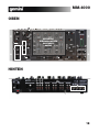
1
19” 4 Channel Mixer With Effects
MM-4000
OPERATIONS MANUAL
MANUAL DE INSTRUCCIONES
MANUEL D’INSTRUCTIONS
BEDIENUNGSHANDBUCH
FOR ENGLISH READERS
PARA LECTORES EN ESPAÑOL
UTILISATEURS FRANCAIS
FÜR DEUTSCHE LESER
Page 2 ~ Page 6
Página 7~ Página 11
Page 12~ Page 16
Seite 17 ~ Seite 21
PLEASE READ BEFORE USING APPLIANCE
IMPORTANT WARNING AND SAFETY INSTRUCTIONS!
CAUTION
RISK OF ELECTRIC
SHOCK DO NOT
OPEN!
CAUTION: This product satisfies FCC regulations when shielded cables and connectors are used to connect the unit to other equipment. To prevent electromagnetic interference with electric appliances such as radios and televisions, use shielded cables and connectors for connections.
The exclamation point within an equilateral triangle is intended to alert the user to the presence of important operating and maintenance (servicing) instructions in the literature accompanying the appliance.
The lightening flash with arrowhead symbol, within an equilateral triangle, is intended to alert the user to the presence of uninsulated “dangerous voltage” within the product’s enclosure that may be of sufficient magnitude to constitute a risk of electric shock to persons.
READ INSTRUCTIONS: All the safety and operating instructions should be read before the product is operated.
RETAIN INSTRUCTIONS: The safety and operating instructions should be retained for future reference.
HEED WARNINGS: All warnings on the product and in the operating instructions should be adhered to.
FOLLOW INSTRUCTIONS: All operating and use instructions should be followed.
CLEANING: The product should be cleaned only with a polishing cloth or a soft dry cloth. Never clean with furniture wax, benzine, insecticides or other volatile liquids since
they may corrode the cabinet.
ATTACHMENTS: Do not use attachments not recommended by the product manufacturer as they may cause hazards.
WATER AND MOISTURE: Do not use this product near water, for example, near a bathtub, wash bowl, kitchen sink, or laundry tub; in a wet basement; or near a swimming
pool; and the like.
ACCESSORIES: Do not place this product on an unstable cart, stand, tripod, bracket, or table. The product may fall, causing serious injury to a child or adult, and serious damage to the product. Use only with a cart, stand, tripod, bracket, or table recommended by the manufacturer, or sold with the product. Any mounting of the product should follow the manufacturer’s instructions, and should use a mounting accessory recommended by the manufacturer.
CART: A product and cart combination should be moved with care. Quick stops, excessive force, and uneven surfaces may cause the product and cart combination to overturn. See Figure A.
VENTILATION: Slots and openings in the cabinet are provided for ventilation and to ensure reliable operation of the product and to protect it from overheating, and these openings must not be blocked or covered. The openings should never be blocked by placing the product on a bed, sofa, rug, or other similar surface. This product should not be
placed in a built-in installation such as a bookcase or rack unless proper ventilation is provided or the manufacturer’s instructions have been adhered to.
POWER SOURCES: This product should be operated only from the type of power source indicated on the marking label. If you are not sure of the type of power supply to your
home, consult your product dealer or local power company.
LOCATION: The appliance should be installed in a stable location.
NON-USE PERIODS: The power cord of the appliance should be unplugged from the outlet when left unused for a long period of time.
GROUNDING OR POLARIZATION:
• If this product is equipped with a polarized alternating current line plug (a plug having one blade wider than the other), it will fit into the outlet only one way. This is a safety feature. If you are unable to insert the plug fully into the outlet, try reversing the plug. If the plug should still
fail to fit, contact your electrician to replace your obsolete outlet. Do not defeat the safety purpose of the polarized plug.
• If this product is equipped with a three-wire grounding type plug, a plug having a third (grounding) pin, it will only fit into a grounding type
power outlet. This is a safety feature. If you are unable to insert the plug into the outlet, contact your electrician to replace your obsolete outlet. Do not defeat the safety purpose of the grounding type plug.
Fig. A
POWER-CORD PROTECTION: Power-supply cords should be routed so that they are not likely to be walked on or pinched by items placed upon or against them, paying particular attention to cords at plugs, convenience receptacles, and the point where they exit from the product.
OUTDOOR ANTENNA GROUNDING: If an outside antenna or cable system is connected to the product, be sure the antenna or cable system is grounded so as to provide
some protection against voltage surges and built-up static charges. Article 810 of the National Electrical Code, ANSI/NFPA 70, provides information with regard to proper
grounding of the mast and supporting structure, grounding of the lead-in wire to an antenna discharge unit, size of grounding conductors, location of antenna-discharge unit,
connection to grounding electrodes, and requirements for the grounding electrode. See Figure B.
LIGHTNING: For added protection for this product during a lightening storm, or when it is left unattended and unused for long periods of time, unplug it from the wall outlet and
disconnect the antenna or cable system. This will prevent damage to the product due to lightening and power-line surges.
POWER LINES: An outside antenna system should not be located in the vicinity of overhead power lines or other electric light or power circuits,
or where it can fall into such power lines or circuits. When installing an outside antenna system, extreme care should be taken to keep from
touching such power lines or circuits as contact with them might be fatal.
OVERLOADING: Do not overload wall outlets, extension cords, or integral convenience receptacles as this can result in a risk of fire or electric
shock.
OBJECT AND LIQUID ENTRY: Never push objects of any kind into this product through openings as they may touch dangerous voltage points
or short-out parts that could result in a fire or electric shock. Never spill liquid of any kind on the product.
SERVICING: Do not attempt to service this product yourself as opening or removing covers may expose you to dangerous voltage or other hazards. Refer all servicing to qualified service personnel.
Fig. B
DAMAGE REQUIRING SERVICE: Unplug this product from the wall outlet and refer servicing to qualified service personnel under the following conditions:
• When the power-supply cord or plug is damaged.
• If liquid has been spilled, or objects have fallen into the product.
• If the product has been exposed to rain or water.
• If the product does not operate normally by following the operating instructions. Adjust only those controls that are covered by the operating instructions as an improper
adjustment of other controls may result in damage and will often require extensive work by a qualified technician to restore the product to its normal operation.
• If the product has been dropped or damaged in any way.
• When the product exhibits a distinct change in performance, this indicates a need for service.
REPLACEMENT PARTS: When replacement parts are required, be sure the service technician has used replacement parts specified by the manufacturer or have the same
characteristics as the original part. Unauthorized substitutions may result in fire, electric shock, or other hazards.
SAFETY CHECK: Upon completion of any service or repairs to this product, ask the service technician to perform safety checks to determine that the product is in proper operating condition.
WALL OR CEILING MOUNTING: The product should not be mounted to a wall or ceiling.
HEAT: The product should be situated away from heat sources such as radiators, heat registers, stoves, or other products (including amplifiers) that produce heat.
2
MM-4000
TOP
12
8
29
13
21
28
15
16
10
15
14
17
ALL CHANNELS
HAVE THE SAME
FEATURES
23
19
24
31
11
18
22
30
18
20
25
26
27
9
BACK
3
4
5
6
2
8
1
7
3
MM-4000
INTRODUCTION:
Congratulations on your purchase of Gemini MM-4000 19” 4 channel
stereo mixer with effects. This-state-of-the-art mixer features the latest
technological advances and is backed by a 1 year warranty, excluding the
cross fader. The cross fader is backed by a separate 90 day warranty.
Prior to use we suggest that you carefully read all the instructions.
6
FEATURES:
- 4U 19" rack mounted audio EFX mixer
- 4 stereo channels
- 6 line and 2 phono RCA inputs
- 1 balanced XLR master microphone input
- 4 unbalanced ¼” (6.35mm jack) Mic channel inputs
- Master, zone & record RCA outputs
- Balanced XLR master output
- 3 band rotary line EQ control per channel
- 8 effect DSP module w/16 presets
PRECAUTIONS:
NOTE: CONNECTING A LINE LEVEL DEVICE TO A PH INPUT MAY CAUSE THAT
MIXER CHANNEL TO OVERLOAD AND OR DISTORT.
7
GROUNDING SCREW
When using (a) turntable(s), you will need to ground the RCA
cable(s) by screwing in the grounding fork(s) to the GROUNDING
SCREW located on the rear panel of the MM-4000 mixer.
Attach a PHONO (Turntable) ground line to the silver GROUND
THUMB SCREW that is situated at the bottom middle of the rear
panel.
8
MIC (MICROPHONE) INPUTS
The MM-4000 has 5 MIC (MICROPHONE) inputs 1 main mic input
located on the top panel, which is controlled by its own volume
rotary, and four auxiliary MIC inputs located on the back panel.
The AUX MIC inputs are controlled by thier corresponding channels
fader, when that channels selector switch (12) is set to the MIC
position.
1. All instructions should be read before using this equipment.
2. To reduce the risk of electrical shock, do not open the unit.
Please refer all servicing needs to a Gemini-qualified service
technician.
3. Do not expose this unit to direct sunlight or a heat source such
as a radiator or stove.
9
4. This unit should be cleaned only with a damp cloth. Avoid solvents or other cleaning detergents.
5. When moving this equipment it should be placed in its original
carton and packaging. This will reduce the risk of damage during
transit.
IN THE USA ~ IF YOU EXPERIENCE PROBLEMS WITH THIS UNIT CALL GEMINI CUSTOMER SERVICE AT:
1 (732) 346-0061. DO NOT ATTEMPT TO RETURN THIS EQUIPMENT TO YOUR DEALER.
CONNECTIONS:
1
CONTROLS:
BALANCED OUTPUTS
The MM-4000 has balanced XLR outputs controlled by the master
output rotary
3
The MASTER RCA OUTPUT
connects the mixer to your main amplifier using standard audio
cables with RCA-type connectors.
4
The RECORD RCA OUTPUT
The RECORD output jacks can be used to connect the mixer to the
record input of your recording unit, thus enabling you to record your
mix with RCA cables.
5
10
MICROPHONE VOLUME
Allows you to adjust the volume of the microphone signal for MIC
input (1) which is located above this volume rotary (see above) .
11
MICROPHONE EQ and TALKOVER SWITCH
The MICROPHONE EQ Let’s you to control the low frequency and
the high frequency of the microphone signal.The TALKOVER switch
allows you to quickly attenuate the main output so the microphone
can be heard over the main music program.
POWER INLET
The MM-4000 comes with a standard three prong power cord. The
power section of the MM-4000 is fused protected. Replace fuses
with only 250v 500mAL fuses. For foriegn voltages you can switch
the voltage selector from 115v to 230V
2
ZONE OUTPUT
The ZONE OUTPUT is the same as the MASTER output but has its
own seperate volume control, you can use the ZONE OUTPUT to
control a seperate set of speakers for example in the DJ booth or
seperate bar/outdoor area.
HEADPHONE OUTPUT
The HEADPHONE OUTPUT located at the front bottom right hand
corner of the MM-4000 will accept any headphone with a standard
1/4” connector and or adapter and will allow you to CUE your music
program before you play it, you can adjust the volume and PGM mix
of the HEADPHONE (see CONTROLS).
Then when all of your connections have been made turn on the
mixer by pressing the POWER SWITCH.
6. DO NOT EXPOSE THIS UNIT TO RAIN OR MOISTURE.
7. DO NOT USE SPRAY CLEANERS OR LUBRICANTS ON
CONTROLS, SURFACES OR SWITCHES.
CHANNEL INPUTS
Now you may plug the RCA’s from your playable medium into each
input to be connected to their respective CHANNELS (CH).
The MM-4000 has eight (8) inputs, (2) of which are PHONO inputs
and are pre-amped for turntable use. There is also a grounding
screw for both PHONO inputs located between channel (1) and
channel (2) on the rear panel (see below).
MIXER CHANNELS
(NOTE: ALL 4 CHANNELS HAVE THE SAME FEATURES)
12
CHANNEL INPUT SELECTOR
The CHANNEL INPUT SELECTOR switches allow you to choose
which input will be controlled by that channels corresponding
volume FADER.
For example on CHANNEL (1) the INPUT SELECTOR allows you to
choose between PHONO 1,LINE 1 and MIC 2 , and also on
CHANNEL (2) you can switch between PHONO 2, LINE 2 and
MIC 3 and on CHANNEL (3) you can select either LINE 3,LINE 4 or
MIC 4 input, then on CHANNEL (4) you can choose between
LINE 5, LINE 6 and MIC 5.
13
CHANNEL ROTARY GAIN
The CHANNEL ROTARY GAIN allows you to boost the signal of
each individual channel depending on how low or high its input
level is.
4
MM-4000
CONTROLS:
CONTROLS:
(CONTINUED)
(CONTINUED)
3 BAND EQUALIZER
The 3 BAND EQUALIZER adjust the tone of each CHANNEL by
giving you a choice 3 frequencies (BANDS) to adjust , from LOW,
MIDRANGE (MID) and HIGH’s ,you can use the adjustment knobs to
higher or lower the 3 separate frequencies till the sound of the music
program is appropriate for your listening environment.
25
ZONE VOLUME ROTARY
Controls the volume level of the ZONE OUTPUT .
26
MASTER VOLUME ROTARY
The MASTER VOLUME ROTARY knob adjust the volume of the
MAIN OUTPUT.
15
EFFECT ASSIGN
The EFFECT ASSIGN buttons allow you to choose which channel
(LINE or MIC) will be sent to the effects section, either one or all
channels can be selected at once (see effects section).
27
CUE VOLUME ROTARY KNOB
The CUE VOLUME ROTARY KNOB adjusts your HEADPHONE
MONITOR OUTPUT volume.
16
CHANNEL CUE SELECTOR
The CHANNEL CUE SELECTOR allows you to choose which
channel will be heard in the headphones, one or all can be pressed at
the same time, when pressed a red LED will illuminate indicating the
CUE is in the ON position
14
17
CHANNEL VOLUME FADER
After you have chosen which input you will use with the INPUT
SELECTOR the corresponding CHANNEL FADER will allow you to
adjust the volume for that particular CHANNEL.
18
CROSSFADER ASSIGNMENT
The fader assignment rotary allows you to assign which two of the 4
channels will be controlled by the CROSSFADER.There are 5
selections for either side of the CROSSFADER which can be either
CHANNEL 1,2,3,4 or OFF, In the OFF position the CROSSFADER
will not affect the volume of any CHANNEL.
19
CROSSFADER
The CROSSFADER allows you to mix evenly from one source to
another. On the MM-4000 The CROSSFADER is assignable between
either channels (1) and (2) or channels (3) and (4) depending on the
position of the fader assignment push button (see above).
The CROSS FADER on the MM-4000 is also removable and if the
need arises can be replaced.The RG-45 (RAILGLIDE™)
DUAL-RAIL CROSS FADER, which has internal dual stainless steel
rails that allow the slider to ride smoothly and accurately from end to
end can be purchased from your local GEMINI dealer.
NOTE: WHEN USING THE CROSS FADER LIGHTLY GLIDE THE FADER BACK AND
FORTH. PRESSING DOWN ON THE CONTROLS CAN BEND CONTACTS AND CAUSE A
LOSS OF SOUND.
20
CUE/PGM FADER
The CUE/PGM FADER determines the mix between the chosen
CHANNEL CUE SELECTION and the MAIN OUTPUT mix.
To the left is the CUE program and to the right is MAIN OUTPUT.
21
POWER SWITCH
Main POWER switch (see above).
22
VU METER
The MM-4000 has a VU METER that allows you to monitor the
decibel levels of the LEFT and RIGHT MASTER output.
It also has two settings (SEE BELOW)
23
24
19
VU METER SETTING SWITCH
The VU SETTING SWITCH allows you to choose between two VU
display modes, In the CUE position the VU will display the levels of
the headphone CUE, and in the MASTER position the VU will display
the MASTER output levels.
MONO/STEREO
The MONO/STEREO switch allows you to change the output of the
MM-4000 to either MONO output or STEREO output depending on
the nature of the system you are playing through, for example some
nightclub systems are wired in MONO, this switch gives you the
choice to change the output of the MM-4000 to either MONO or
STEREO.
EFFECTS:
28
ON/OFF
Turns the effect section ON or OFF.
29
WET/DRY ROTARY
Adjusts the mix between the (DRY) input signal being sent from the
effect assigned channels and the processed (WET) signal coming
from the effects section.
30
CUE EFX BUTTON
Like the CUE SELECT BUTTONS the CUE EFX BUTTON lets you
monitor the effect in the headphone before you mix it in using
DRY/WET ROTARY.
31
EFFECT SELECTION ROTARY
Lets you choose between the 16 different built in effect choices
which consist of:
ROOM REVERB:
A short REVERB that mimics the sound of being in a small ROOM
this REVERB has three (3) different settings.
PLATE REVERB:
An artificially created REVERB that uses a plate of metal to
simulate a highly reflective ROOM sound, this REVERB also has
three (3) different settings.
HALL REVERB:
Is a longer REVERB that mimics the sound of being in a concert
HALL this also has three (3) different settings.
ECHO:
ECHO is similar to a delay effect which basically repeats the sound
and then decays or trails it out mimicing the sound of a canyon or
very large area with reflective qualities, this EFFECT also has three
(3) different settings.
VOCAL CANCELLATION:
Can be used to cancel or remove the vocals in a song so you can
sing over it.
AUTO WAH:
Is a FILTER that automatically opens and closes giving you the
sound similar to that of a WAH WAH pedal used with guitars.
FLANGER:
A FLANGER sounds like two records being played at the exact same
time, which give you a tunnel or jet plane type of sound.
AUTO PAN:
AUTO PAN will automaticaly pan the sound from the left speaker to
the right speaker at a pre-determined tempo.
5
MM-4000
FADER REPLACEMENT:
1. UNSCREW THE FADER (B) SCREWS. DO NOT TOUCH INSIDE
SCREWS (C) CAREFULLY REMOVE OLD CROSS FADER AND UNPLUG
CABLE (D)
2. PLUG IN THE NEW CROSS
FADER INTO CABLE (D) AND
PLACE BACK INTO MIXER.
3. SCREW THE CROSS FADER TO
MIXER WITH THE FADER PLATE
SCREWS (B)
4. REPLACE THE FACE OF THE
MIXER AND SCREW THE FOUR
SCREWS BACK IN AND REPLACE THE FADER KNOBS.
SPECIFICATIONS:
INPUTS:
Phono.....................................................................................3mV,47 KOhm
Line..................................................................................150 mV, 27 KOhm
MIC......................................................................1.5 mV, 1 KOhm Balanced
OUTPUTS:
Max...................................................................................20V Peak-to Peak
Rec.....................................................................................225 mV, 5 KOhm
GENERAL:
Frequency Response...............................................20Hz - 20KHz +/- 0.5dB
Distortion..........................................................................................< 0.02%
S/N Ratio...........................................................................Better than 85 dB
Headphone impedance.....................................................................32 Ohm
Power Source ..........................................................115/230v,50/60Hz,20w
Unit Demensions........................................................................19” x 7” x 3”
.......................................................................................(483 x 178 x76mm)
Weight................................................................................10 lbs (4.53 kg)
SPECIFICATIONS SUBJECT TO CHANGE WITHOUT NOTIFICATION FOR IMPROVEMENT
6
POR FAVOR LEA ANTES DE UTILIZAR,
INSTRUCCIONES IMPORTANTES DE SEGURIDAD
PRECAUCIÓN
RIESGO DE SHOCK
ELECTRICO - NO
ABRIR!
ATENCIÓN: Este producto cumple con la normativa legal si se utilizan cables y conectores blindados para conectar la unidad a otro equipo. Para evitar interferencias electromagnéticas con otros aparatos eléctricos, como radios y televisores, deben emplearse cables y conectores blindados.
Los signos de exclamación dentro de un triángulo que puedan aparecer en la documentación que acompaña a la unidad pretenden alertar al usuario de instrucciones de operación o mantenimiento importantes.
El signo de un rayo dentro de un triángulo pretende alertar al usuario de la presencia de "voltaje peligroso" no aislado en el inte-rior de la unidad, que podría ser
de suficiente intensidad como para constituir riesgo de descarga eléctrica.
LEA LAS INSTRUCCIONES: Deben leerse todas las indicaciones de uso y seguridad antes de usar este producto.
CONSERVE LAS INSTRUCCIONES: Las instrucciones de uso y seguridad deben conservarse para referencias futuras.
ATIENDA A LAS ADVERTENCIAS: Deben seguirse todas las advertencias sobre este producto que figuran en el manual de instrucciones.
SIGA LAS INSTRUCCIONES: Deben seguirse todas las instrucciones del manual.
LIMPIEZA: Este producto debe limpiarse con una mopa suave o con un paño seco. Nunca utilice cera para muebles, gasolina, insecticidas u otros líquidos
volátiles, ya que podrían corroer la carcasa.
COMPLEMENTOS: No utilice accesorios que no estén recomendados por el fabricante, pues podrían dañar la unidad.
AGUA Y HUMEDAD: No use este producto cerca de medios acuáticos, como una bañera, un cubo de agua, un fregadero o un
lavadero; tampoco en un sótano húmedo, ni cerca de una piscina o similar.
ACCESORIOS: No coloque el producto sobre un carrito, soporte, trípode, brazo o mesa. Podría caer y causar graves daños a
un niño o adulto, así como a la propia unidad. Úsese sólo con un carrito, soporte, trípode, brazo o mesa recomendado por el fabricante. Al montar la unidad deben seguirse siempre las instrucciones y emplearse accesorios recomendados por el fabricante.
CARRITO: Si el producto va sobre un carrito, debe moverse el conjunto con cuidado. Detenciones bruscas, una fuerza excesiva
o superficies inadecuadas pueden provocar la caída de todo el conjunto. Véase Figura A.
VENTILACIÓN: Las aperturas y ranuras de la carcasa están diseñadas para la ventilación, aseguran un manejo fiable y lo protegen de cualquier sobrecalentamiento, por tanto, nunca deben cubrirse ni bloquearse. Estas aperturas no deben taparse coloFig. A
cando el producto sobre un sofá, una cama, una alfombra o superficies similares. Nunca debe colocarse en una estructura
prefabricada, como una caja o un rack, a menos que tengan la ventilación adecuada o lo permitan las instrucciones del fabricante.
FUENTES DE ALIMENTACIÓN: Esta unidad debe utilizarse exclusivamente con el tipo de suministro eléctrico indicado en la etiqueta correspondiente. Consúltelo antes de enchufar el producto si no está seguro del tipo de suministro del lugar donde lo va a usar.
UBICACIÓN: Este aparato debe colocarse en una ubicación estable.
PERIODOS SIN USARLO: Si no se va a usar la unidad durante un tiempo prolongado, desenchúfelo de la corriente eléctrica.
TOMA DE TIERRA O POLARIZACIÓN:
- Si este producto lleva una clavija de corriente alterna polarizada (con un pivote más grueso que otro, tipo inglés), sólo entrará en una posición. Es una medida
de seguridad. Si no puede introducir la cla-vija en el enchufe, gírela. En ningún caso debe forzarse. Si sigue sin entrar, un electricista debería cambiar el enchufe.
- Si la unidad lleva una clavija con tres pivotes (el tercero corres-ponde a la toma de tierra), sólo entrará en un tipo de enchufe. Se trata de una medida de seguridad. Si el enchufe y la clavija no son compatibles, un electricista deberá cambiar el enchufe. En ningún caso deberá forzarse.
PROTECCIÓN DEL CABLE DE CORRIENTE: Los cables de corriente deben protegerse para que nadie los pise ni corran el
riesgo de pinzarse por elementos colocados encima o que los aprisionen. Debe prestarse especial atención al cable, al enchufe, a
los extensores de cable y al punto por donde el cable sale de la unidad.
TIERRA DE LA ANTENA EXTERIOR: Si el producto lleva conectada una antena exterior o sistema de cables, asegúrese de
que cuenta con la toma de tierra correspondiente, a fin de proteger la unidad de variaciones de voltaje y cargas de electricidad estática. Existe documentación oficial acerca de la correcta utilización de la toma de tierra y de las medidas de seguridad pertinentes, conexión de los electrodos de descarga y sus requisitos. Véase Figura B.
RAYOS: Como protección adicional del producto durante una tormenta eléctrica, o durante periodos prolongados sin usarlo,
desenchúfelo de la corriente y desconecte la antena o sistema de cables. De este modo se protegerá el producto de los daños
Fig. B
que pueda producir la caída de un rayo o las fluctuaciones de la red eléctrica.
LÍNEAS ELÉCTRICAS: Nunca debe situarse un sistema de antena cerca de líneas eléctricas u otros circuitos de corriente. Tampoco debe colocarse en lugares
donde pueda caer sobre dichos circuitos eléctricos. Al instalar un sistema de antenización exterior, debe tomarse la extrema precaución de no tocar dichas líneas
eléctricas, pues el mas minimo contacto puede ser fatal.
SOBRECARGA: No sobrecargue los enchufes de la pared con ladrones o instalando enchufes múltiples, pues correría el riesgo de electrocución o incendio.
ENTRADA DE OBJETOS O LÍQUIDOS: Nunca introduzca objetos de ningún tipo en el interior del producto, pues podrían tocar una parte eléctrica y cortocircuitar el aparato, lo que resultaría en un incendio o descarga eléctrica. No verter nunca ningún líquido sobre el producto.
REPARACIÓN: No intente reparar el producto por cuenta propia, ya que abrir o retirar la carcasa le expondría a un voltaje peligroso u otros peligros. Diríjase
siempre a un centro de servicio técnico autorizado.
DAÑOS QUE REQUIEREN REPARACIÓN: Desenchufe el aparato de la corriente y diríjase a un servicio técnico autorizado si se da alguna de las siguientes
situaciones:
- El cable de alimentación o la clavija están dañados.
- Se ha vertido líquido o ha caído algún objeto sobre la unidad.
- El aparato se ha expuesto a la lluvia o a salpicaduras.
- La unidad se ha caído al suelo o dañado de algún modo.
- El aparato no funciona con normalidad, ni aun siguiendo las instrucciones. Ajuste sólo los mandos que se indican en las instrucciones, ja que la manipulación
inadecuada de otros controles podría dañar la unidad y requeriría un mayor trabajo de un técnico para restablecer su funcionamiento normal.
- Si el producto muestra anomalías en su funcionamiento, necesita revisión por parte de un servicio técnico autorizado.
RECAMBIOS: Cuando se necesite alguna pieza de recambio, asegúrese de que el servicio técnico utilice piezas originales autori-zadas o que tengan las mismas características que las originales. Los reemplazos no autorizados pueden causar descargas eléctricas, incendios u otros daños.
COMPROBACIÓN DE SEGURIDAD: Tras la reparación, solicite al técnico que efectúe las comprobaciones de seguridad necesarias para determinar que el producto se encuentra en las condiciones adecuadas para su funcionamiento.
MONTAJE EN UNA PARED O TECHO: Este producto nunca debe montarse en una pared o en el techo.
CALOR: Este producto debe alejarse de fuentes de calor, como radiadores, estufas u otros aparatos que irradien calor, incluyendo amplificadores.
7
MM-4000
PANEL SUPERIOR
12
8
29
13
21
28
15
16
10
LAS MISMAS
CARACTERISTICAS
EN CADA CANAL
15
14
22
30
23
24
31
17
11
18
19
18
20
25
26
27
9
PANEL TRASERO
3
4
5
6
2
8
1
7
8
MM-4000
INTRODUCCION:
Felicidades por la compra de la mesa de mezclas de 19” 4 canales
Gemini MM-4000. Esta mesa de mezclas está amparada por 1 año de
garantía*, excluyendo el crossfader. El crossfader sólo goza de 90 días de
garantía. Antes de usar le rogamos lea detenidamente estas instrucciones.
6
CARACTERÍSTICAS:
- Mezclador de audio 4U 19" con Efectos
- 4 Canales estéreo.
- 6 Entradas RCA de línea y 2 de phono
- 1 Entrada Micrófono XLR balanceada.
- 4 Entradas en canales Jack ¼” para micrófono.
- Salidas RCA Master, Zona y Grabación.
- Salida Master XLR Balanceada.
- EQ 3 bandas por canal.
- Módulo de 8 Efectos pre-programados.
NOTA: CONECTANDO UN APARATO DE LINEA EN UNA ENTRADA DE PH PUEDE
CREAR SOBRECARGA DEL MEZCLADOR Y DISTORSIÓN
7
8
ENTRADA MIC (MICRÓFONO)
La entrada de MIC está alojada en la esquina Trasera de la
MM-4000 y permite cualquier jack 1/4” . Puede controlar la ganancia e incluso graves y agudos de esta entrada.
(Vea VOLUMEN MICRÓFONO).
9
SALIDA de AURICULARES
La SALIDA de AURICULARES localizada en la parte frontal de la
MM-4000 acepta cualquier auricular con un conector standard 1/4” o
adaptador y permite escuchar la mezcla, puede ajustar el volumen
de pre-escucha de la mezcla en los AURICULARES
(Vea CONTROLES).
2.Para evitar el riesgo de shock electric, no abrir la unidad. Por
favor contacte con un servicio técnico Gemini especializado.
3.No exponer esta unidad al Sol directo o fuentes térmicas directas tales como radiadores o estufas.
4. No use disolventes químicos para limpiar la unidad. Limpiar
solamente con un trapo húmedo.
5. Cuando traslade el equipo póngalo en su caja original. Esto reducirá el riesgo de dañar la unidad durante el transporte.
Cuando todas sus conexiones estén realizadas, encienda el
mixer pulsando el INTERRUPTOR DE ALIMENTACIÓN (21).
6. ESTE APARATO NO DEBE EXPONERSE A CHORROS O
SALPICADURAS.
CONTROLES:
7.NO USE SPRAYS LIMPIADORES O LUBRICANTES EN LOS
CONTROLES,INTERRUPTORES O CUBIERTAS DEL EQUIPO.
IN THE USA ~ IF YOU EXPERIENCE PROBLEMS WITH THIS UNIT CALL GEMINI CUSTOMER SERVICE AT:
1 (732) 346-0061. DO NOT ATTEMPT TO RETURN THISE EQUIPMENT TO YOUR DEALER.
10
VOLUMEN MICROFÓNO
Permite ajustar el volumen del micrófono.
11
EQ MICROFONO Y TALKOVER
La sección EQ del MICROFÓNO le permite controlar los tonos altos
y bajos de la señal de micrófono. El control de TALKOVER permite
rápidamente atenuar la señal de la salida principal y pasar la señal
de micrófono por encima de la principal.
CONEXIONES:
1
ENTRADA PRINCIPAL DE ENERGÍA Y SWITCH
Esta sección es para la conexión de alimentación de CA, El
MM-4000 viene con una clavija estándar de 3 cable de alimentación de CA y tiene un conmutador automatico de fuente
de alimentación interna.
2
SALIDAS BALANCEADAS
La MM-4000 salidas balanceadas por XLR controladas por el control de salida master.
3
SALIDA MASTER RCA
Conecta el mezclador al amplificador principal usando cables estandar de conectores RCA.
4
SALIDA DE GRABACIÓN RCA
La salida de GRABACIÓN puede usarse para conectar el mezclador a una grabadora, permitiendo grabar su mezcla con cables
RCA.
5
SALIDA ZONA
permite controlar una salida separada para monitorizar en la cabina
de DJ u otra zona separada.
TORNILLO TOMA DE TIERRA
Cuando se use con giradiscos, necesitará conectar el cable de tierra
del RCA y atornillarlo a la TOMA DE TIERRA de la parte trasera del
MM-4000
Junte la línea de tierra de PHONO (giradiscos) al tornillo posterior de
TOMA DE TIERRA que está situada en la parte central trasera del
equipo.
PRECAUCIONES:
1.Todas las instrucciones deberán ser leídas antes de usar este
equipo.
CANALES DE ENTRADA
Ahora puede conectar los RCA de su fuente de sonido a cada entrada de canal (CH). La MM-tiene ocho (8) entradas, 2 de las cuales
son PHONO pre-amplificadas para uso con giradiscos. Hay una
toma de tierra para ambas entradas situada entre el canal (1) y el
canal (2) en el panel trasero (ver abajo).
CANALES MIXER
(NOTA: LOS 4 CANALES TIENES LAS MISMAS CARACTERÍSTICAS)
12
SELECTOR ENTRADA CANALES
El Selector de ENTRADA de CANALES permite escoger que entrada será controlada por el FADER.
Por ejemplo en el CANAL (1) el SELECTOR de ENTRADA permite
escoger entre PHONO 1, LINE 1 y MIC 2, y en el CANAL(2) el
SELECTOR de ENTRADA permite escoger entre PHONO 2,
LINE 2 y MIC 3 y en el CANAL (3) permite escoger entre LINE 3,
LINE 4, y MIC 4 en el CANAL (4) permite escoger entre LINE 5,
LINE 6 y MIC 5.
13
GANACIA ROTATIVA DE CANAL
La GANACIA ROTATIVA DE CANAL permite aumentar la señal de
cada canal individual dependiendo de qué nivel de entrada sea.
14
ECUALIZACION DE 3 BANDAS
El ECUALIZACION DE 3 BANDAS ajusta el tono de cada
CANALES dando la opción de 3 frecuencias (BANDAS) para ajustar GRAVES, MEDIOS (MID) y AGUDOS,puede usar este ajuste
para aumentar o disminuir las 3 frecuencias por separado hasta que
el tono del programa musical sea el apropiado para la escucha.
9
MM-4000
CONTROLES:
15
ASIGNACIÓN DE EFECTOS
Los botones de ASIGNACIÓN DE EFECTOS permiten escoger qué
canal (LINE A o MIC) será enviado a la sección de efectos, individualmente o todos los canales pueden ser seleccionados la misma vez
(ver sección efectos).
16
CUE DE CANAL
Los botones de CUE DE CANAL permiten elegir que canal desea
monitorizar a través de sus auriculares, puede elegir desde uno hasta
cualquier combinación de los cinco.
17
VOLUMEN DE CANAL
Después de elegir que entrada desea con el SELECTOR DE ENTRADA el correspondiente FADER DE CANAL le permitirá ajustar el
volumen de ese CANAL en particular.
18
19
CONTROLES
(continuación)
ASIGNACIÓN CROSSFADER
El control de asignación de crossfader permite asignar qué dos
canales de los cuatro disponibles será controlado por el CROSSFADER. Hay 5 selecciones por lado del CROSSFADER las cuales
pueden ser CANAL 1,2,3,4 o OFF, en la posición OFF el CROSSFADER no afectará al volumen de ningún canal.
CROSSFADER
El CROSSFADER permite mezclar de una fuente a otra. En la
MM-4000 el CROSSFADER es asignable entre los canales (1) y (2) o
los canales (3) y (4) dependiendo de la posición del botón de asignación del crossfader ( ver arriba ) CROSS FADER del MM-4000
es reemplazable en caso de que fuera necesario. El CROSS FADER
RG-45 (RAILGLIDE™) DE DOBLE RAIL, que tiene internamente dos
guías de acero que permiten un desplazamiento suave y preciso de
fin a fin puede comprarse como accesorio en cualquier distribuidor
GEMINI.
NOTA: AL USAR EL CROSSFADER DESPLACE SUAVEMENTE EL FADER. SI
PRESIONA HACIA ABAJO PUEDE DOBLAR LOS CONTACTOS INTERNOS Y CREAR
PERDIDAS DE SONIDO.
20
CONTROL CUE/PGM MIX
Ajusta la mezcla entre la señal de CUE y la salida master
21
INTERRUPTOR DE ALIMENTACIÓN
El interruptor de alimentación enciende o apaga la MM-4000.
22
VU METER
La MM-4000 tiene un VU METER estéreo que permite monitorizar el
nivel de decibelios de las salidas IZQUIERDA y
DERECHA MASTER.
23
INTERRUPTOR DE AJUSTES DEL VU-METER
El interruptor de ajustes de Vu-meter permite escoger entre 2 modos
de mostrar el Vu-meter. En la posición CUE el Vu-meter mostrará los
niveles de audio en los auriculares, y en la posición de MASTER
mostrará el nivel de volumen en la salida master.
24
19
MONO/STEREO
El interruptor MONO/STEREO permite cambiar la salida de la
MM-4000 a MONO o STEREO dependiendo del sistema que esté utilizando, por ejemplo algunos sistemas están instalados en mono, este
interruptor le permite escoger y cambiar la salida de la MM-4000 a
MONO o STEREO.
(continuación)
25
CONTROL DE VOLUMEN DE ZONA
Controla el nivel de volumen de la SALIDA de ZONA.
26
SALIDA MASTER:
El control rotativo de SALIDA MASTER ajusta el volumen de salida
de la señal MASTER.
27
VOLUMEN DE CUE
El CONTROL ROTATIVO DE VOLUMEN DE CUE ajusta el volumen
de salida de sus AURICULARES MONITOR.
EFECTOS:
28
ON/OFF
Activa la sección de efectos ON o OFF.
29
CONTROL WET/DRY
Ajusta la mezcla entre la señal de entrada (DRY) enviada desde los
canales asignados de efectos y la señal procesada (WET) procedente de la sección de efectos.
30
BOTÓN CUE EFX
Igual que los BOTONES DE SELECCIÓN DE CUE el BOTÓN DE
CUE EFX permite monitorizar el efecto en los auriculares antes de
que lo mezcle usando el CONTROL DRY/WET.
31
CONTROL SELECCIÓN DE EFECTOS
Permite escoger entre los 16 diferentes efectos, tales como:
ROOM REVERB:
Un REVERB corto que imita el sonido reproducido al estar en una
SALA pequeña, este efecto tiene tres (3) ajustes diferentes.
PLATE REVERB:
Un REVERB artificial el cual usa un plato de metal para simular un
sonido reflectante, este REVERB también tiene tres (3) ajustes.
HALL REVERB:
Es un REVERB más largo que imita el sonido de estar en un
concierto, este también tiene tres (3) ajustes.
ECHO:
El ECHO es similar al efecto DELAY el cual básicamente repite el
sonido y aparece o desaparece imitando el sonido reproducido en
una área grande con cualidades de reflexión de sonido, este efecto
tiene también tres (3) ajustes distintos.
VOCAL CANCELLATION:
Puede ser utilizado para cancelar o quitar las partes vocales en una
canción de manera que puedes cantar por encima.
AUTO WAH:
Es un filtro que automáticamente se abre y se cierra dando un
sonido similar al WAH WAH usado en los pedales de guitarras.
FLANGER:
Un FLANGER suena como dos discos sonando al mismo tiempo,
dando un sonido tipo túnel o avión jet.
AUTO PAN:
El AUTO PAN automáticamente realizará un movimiento
panorámico del sonido desde el altavoz izquierdo al derecho con un
tempo predeterminado.
10
MM-4000
REEMPLAZAR EL CROSSFADER:
1. DESATORNILLE LOS TORNILLOS DEL FADER (B). NO TOQUE LOS
TORNILLOS INTERIORES (C) CON CUIDADO QUITE EL VIEJO CROSS
FADER Y DESCONECTE EL CABLE (D)
2. CONECTE EL NUEVO CROSS
FADER EN EL CABLE (D) Y INSERTELO EN SU LUGAR.
3. ATORNILLE EL CROSS FADER AL
MEZCLADOR CON LOS TORNILLOS
DE LA CARATULA (B)
4. COLOQUE LA CARATULA DEL
MEZCLADOR Y ATORNILLE LOS CUATRO TORNILLOS. COLOQUE DE NUEVO LOS BOTONES DE LOS FADERS.
ESPECIFICACIONES:
ENTRADAS:
Phono.....................................................................................3mV,47 KOhm
Linea................................................................................150 mV, 27 KOhm
MIC......................................................................1.5 mV, 1 KOhm Balanced
SALIDAS:
Max...................................................................................20V Peak-to Peak
Rec.....................................................................................225 mV, 5 KOhm
GENERAL:
Respuesta en frecuencia.........................................20Hz - 20KHz +/- 0.5dB
Distorsión.........................................................................................< 0.02%
S/N Ratio...........................................................................Better than 85 dB
iImpedancia auriculares....................................................................32 Ohm
Alimentación.............................................................115/230v,50/60Hz,20w
Dimensiones..............................................................................19” x 7” x 3”
.....................................................................................(483 x 178 x 76 mm)
Peso.....................................................................................10 lbs (4.53 kg)
ESPECIFICACIONES SUJETAS A VARIACION SIN PREVIO AVISO PARA MEJORAS
11
AVANT TOUTE UTILISATION DE L'APPAREIL, MERCI DE PRENDRE CONNAISSANCE DES INSTRUCTIONS
D'UTILISATION & DE SECURITE! RISQUE DE CHOC ÉLECTRIQUE, NE PAS OUVRIR!
ATTENTION
RISQUE DE CHOC
ÉLECTRIQUE
NE PAS OUVRIR!
ATTENTION: Cet appareil répond aux certifications FCC lorsqu'il est connecté à d'autres appareils à l'aide de cordons blindés. Afin de prévenir tout risque de parasites électromagnétiques avec un poste radio ou TV, veuillez utiliser des cordons blindés.
Le point d'exclamation situé dans un triangle est destiné à attirer votre attention durant l'utilisation de votre appareil ou d'un entretien périodique de ce dernier. Vous en trouverez plusieurs dans le mode d'emploi de l'appareil.
LIRE LES INSTRUCTIONS: Toutes les instructions et consignes d'utilisation doivent être lues avant l'utilisation de l'appareil.
CONSERVEZ LES INSTRUCTIONS: Nous vous recommandons de conserver les instructions et consignes d'utilisation en cas de nécessité ultérieure.
RESPECT DES CONDITIONS D'UTILISATION: Nous vous recommandons de respecter les instructions d'utilisation.
SUIVRE LES INSTRUCTIONS D'UTILISATION: Nous vous recommandons de respecter la chronologie des instructions d'utilisation.
NETTOYAGE: L'appareil doit être nettoyé avec un chiffon légèrement humide. Ne pas utiliser de produits chimiques corrosifs & volatiles (cire, essence, insecticide…) afin de
ne pas endommager l'appareil.
CORDON: Ne pas utiliser de cordons non préconisés par le fabricant afin de ne pas endommager l'appareil.
EAU & HUMIDITE: Ne pas utiliser l'appareil à proximité d'une source d'eau (cuisine, salle de bain, lavabo…), ni dans un endroit sujet à l'humidité (piscine…).
ACCESSOIRES: Ne pas installer cet appareil sur un support ou dans un endroit instable. L'appareil pourrait tomber au risque de blesser une personne et être endommagé.
Veiller à utiliser des accessoires (Pied, support, crochet..) recommandés par le fournisseur ou vendu avec l'appareil. Tout montage ou installation doit respecter les instructions du fabricant et utiliser des accessoires d'installation recommandés par le fabricant.
TRANSPORT SUR CHARIOT: Tout produit installé sur un chariot doit être manipulé avec précaution. Un déplacement brusque ou trop rapide sur une surface non plane
pourrait entraîner la chute de l'ensemble et endommager l'appareil. Voir Figure A.
VENTILATION: Les ouvertures et ouïes d'aération situées sur l'appareil permettent une ventilation optimale de ce dernier afin d'éviter toute surchauffe. Ces ouvertures ne
doivent jamais être obstruées. Ne pas placer l'appareil sur un support souple risquant de bloquer les ouïes d'aération (Lit, sofa, canapé…). Si l'appareil est intégré dans une
installation ou dans un rack, veillez à la ventilation et consultez le fabricant pour toute information complémentaire.
ALIMENTATION: Veillez à respecter la tension d'alimentation située au dos de l'appareil. Si vous n'êtes pas certain de la tension d'utilisation dans votre pays, contactez
votre revendeur.
EMPLACEMENT: Veillez à installer l'appareil sur un support stable.
PERIODE DE NON UTILISATION: Débranchez le cordon d'alimentation de l'appareil en cas de non utilisation prolongée.
MISE A LA TERRE:
- Si l'appareil est équipé d'une alimentation à courant alternatif (Prise possédant un contact plus large que l'autre), celle-ci se connectera
correctement à la prise uniquement si vous respectez le sens de branchement. Il s'agit là d'une mesure de sécurité. Si vous n'arrivez pas à
insérer la fiche dans la prise, inversez la fiche. Si vous ne pouvez toujours pas insérer cette dernière, contactez un électricien afin de remplacer votre prise électrique qui est obsolète. Veillez à respecter cette consigne.
- Si l'appareil est équipé d'une fiche d'alimentation avec terre, veillez à la connecter à une prise électrique équipée d'une connexion à la
terre. Il s'agit d'une mesure de sécurité. Si vous ne pouvez insérer la fiche dans la prise électrique, contactez un électricien afin de remplacer
votre prise électrique qui est obsolète. Il est important de respecter cette mesure de sécurité.
Fig. A
INSTALLATION DU CORDON D'ALIMENTATION: Les cordons d'alimentation doivent être déroulés et rangés proprement afin d'éviter de se
prendre les pieds dedans, en particulier les cordons reliés aux prises électriques.
ANTENNE EXTERIEURE: Si vous reliez votre appareil à une antenne ou un câble extérieur, assurez-vous de la présence d'une connexion à la terre afin d'éviter les surtensions et les décharges d'électricité statique. L'article 810 du National Electrical Code, ANSI/NFPAS 70, précise toutes les informations nécessaires afin d'effectuer correctement le branchement à la terre du pylône ou de la structure porteuse, la connexion du câble à l'antenne de décharge, dimensions des connecteurs de mise à la terre,
connexions des électrodes, consignes de mise à la terre des électrodes. Voir Schéma B.
ORAGE/FOUDRE: En cas d'orage et de non utilisation prolongée, débranchez le cordon d'alimentation, le câble d'antenne et les cordons audio. Ceci afin d'éviter les dégâts
occasionnés par la foudre et les surcharges électriques.
LIGNES ELECTRIQUES: Une antenne extérieure ne doit pas être située à proximité immédiate de lignes électriques et/ou d'un transformateur électrique, afin de ne pas
tomber dessus en cas de chute. Lors de l'installation d'une antenne extérieure, veillez à éviter tout contact avec des lignes électriques : tout contact peut être fatal.
SURCHARGE: Ne surchargez pas les prises électriques, blocs multiprises & rallonges en y connectant trop d'appareils. Ceci afin d'éviter tout
risque de surcharge électrique ou d'incendie (Surchauffe).
INSERTION D'OBJET & DE LIQUIDE: N'insérez pas d'objets dans les fentes ou ouvertures de l'appareil afin d'éviter tout risque de choc
électrique et d'incendie. Ne jamais renverser de liquide sur l'appareil.
SERVICE APRES VENTE: N'essayez pas de réparer cet appareil ; en l'ouvrant ou en le démontant afin d'éviter tout risque de choc électrique. En cas de problème, veuillez prendre contact avec votre revendeur.
PANNE/SITUATION NECESSITANT UN RETOUR EN SAV: Débranchez l'appareil de la prise électrique, remettez le dans son emballage
d'origine et contactez votre revendeur en tenant compte des situations suivantes :
- Lorsque le cordon d'alimentation est endommagé.
Fig. B
- Si un liquide a été renversé dessus.
- Si l'appareil a été exposé à la pluie.
- Si l'appareil ne fonctionne pas correctement malgré le respect des instructions d'utilisation. Ajustez uniquement les réglages préconisés dans le mode d'emploi, toute manipulation ou réglage non conseillés dans ce dernier peut endommager l'appareil et procurer plus de travail en cas d'intervention SAV afin de remettre l'appareil en état de
marche.
PIECES DE RECHANGE: Lorsque vous avez besoin de remplacer des pièces de l'appareil, veillez à utiliser des pièces d'origine ou possédant des caractéristiques identiques. L'utilisation de pièces non autorisées peut endommager l'appareil : surchauffe, court-circuit, choc électrique…
CONTROLE DE SECURITE: Avant de récupérer votre appareil, assurez vous que le SAV a effectué tous les contrôles de sécurité nécessaires afin de vous restituer un appareil en état de marche.
INSTALLATION AU PLAFOND OU SUR UN MUR: Ce type d'installation est déconseillé.
CHALEUR: Veillez à installer l'appareil loin de toute source de chaleur telle que radiateur, réchaud ou tout autre appareil produisant de la chaleur.
recyclage: Cet appareil ne doit pas être considéré comme un déchet domestique à usage unique. Vous devez le déposer dans un point de collecte destiné au recyclage des
appareils électroniques et électroménagers. AInsi vous préserverez l'environnement et éviterez les problêmes de santé publique vis à vis de conséquences négatives; liées à
leur dépôt dans un endroit non approprié. Le recyclage contribue à préserver les ressources naturelles. Pour plus d'informations sur les conditions de recyclage de l'appareil,
veuillez contacter les autorités de votre pays, les institutions locales ou votre revendeur.
12
MM-4000
FACE
SUPERIEURE
12
8
29
13
21
28
15
16
10
MÊME
CARACTÉRISTIQUES
ON EVERY
CANAL
15
14
17
23
19
24
31
11
18
22
30
18
20
25
26
27
9
FACE ARRIERE
3
4
5
6
2
8
1
7
13
MM-4000
INTRODUCTION:
Nos félicitations pour l’achat du mixeur Gemini MM-4000. Cette table de
mixage a été conçue grâce aux dernières avancées technologiques et dispose d’une garantie de 1 ans, à l’exception du crossfader dont la garantie est
de 90 jours. Avant tout utilisation, merci de lire attentivement les instructions
de ce manuel.
6
CARACTERISTIQUES:
- Console de mixage 19’’ x 4U avec effets
- 4 voies stéréo
- 6 lignes, 2 entrées convertibles Phono/Ligne (RCA)
- 1 entrée microphone XLR en face avant
- 4 entrées microphones Jack 6.35mm
- Sorties (RCA): Master, Zone & Record (Enregistrement)
- Sortie symétrique (Master) XLR
•- Corrections paramétriques 3 bandes par voie
- 8 effets DSP intégrés & assignables par voie avec paramètres réglables
NOTE: SI VOUS CONNECTEZ UN APPAREIL DE NIVEAU LIGNE SUR UNE ENTREE
COMMUTEE EN NIVEAU PHONO, LE SON SERA SATURE ET DISTORDU.
7
8
AVERTISSEMENTS:
1. Toutes les instructions de fonctionnement doivent être lues avant l’utilisation du matériel.
2. Afin de réduire le risque de choc électrique, n’ouvrez pas l’appareil.
Veuillez soumettre l’entretien et la réparation au service après vente de
GCI Technologies.
9
3. Ne pas exposer directemement cet appareil aux rayons du soleil ou à
une autre source de chaleur, tel qu’un radiateur ou un poêle.
4. Cet appareil doit être exclusivement nettoyé avec un chiffon légèrement humide. Proscrire solvants et autres détergents.
ALIMENTATION
Cet appareil est livré avec un CORDON SECTEUR à connectez sur
l’embase située en face arrière. La MM-4000 est équipée d’un fusible
de protection. En cas de remplacement, veillez à utiliser un fusible
identique: 250v 500mAL. En fonction du pays d’utilisation, sélectionnez le voltage approprié: 115V ou 230V (France).
2
SORTIE SYMETRIQUE OUTPUT
La console MM-4000 est équipée d’une sortie stéréo symétrique XLR
dont le niveau est contrôlée par le potentiomètre rotatif MASTER.
3
SORTIE MASTER RCA OUTPUT
La sortie MASTER RCA OUTPUT sert à relier la console à l’amplificateur de puissance via tout cordon standard RCA stéréo.
4
SORTIE RECORD RCA OUTPUT
La sortie enregistrement RECORD sert à relier votre console à l’entrée de votre enregistreur via tout cordon standard RCA stéréo.
5
SORTIE ZONE
Permet de contrôler le niveau de la sortie auxiliaire (RETOUR DJ /
Seconde ZONE à sonoriser).
SORTIE CASQUE (HEADPHONE OUTPUT)
La sortie casque HEADPHONE OUTPUT (9) est située en face avant
de votre MM-4000. En branchant votre casque (JACK 6,35mm), vous
pouvez écouter le canal 1, le canal 2, le canal 3 ou le canal 4 et ainsi
préparer votre morceau musical avant de le jouer. Le volume de la sortie casque est réglable, ainsi que la sélection du mélange des sources
(CUE/PGM). Vous reportez à la section REGLAGES pour de plus amples détails.
10
VOLUME MICROPHONE
Ce potentiomètre rotatif permet d’ajuster le volume du MICROPHONE
1 (MIC 1) situé en face avant de la MM-4000 (Voir ci-dessus) .
11
MICROPHONE EQ & TALKOVER
Les réglages EQ MICROPHONE (11) vous permettent d’ajuster les
fréquences aigues et basses de votre micro. Le TALKOVER permet
d’atténuer rapidement le niveau de la musique au profit du microphone
afin de rendre celui-ci plus intelligible.
CONNEXIONS:
1
ENTREE MIC (MICROPHONE) INPUT
L’entrée MIC est située sur le panneau de la face arrière. Utilisez un
connecteur JACK 6,35mm standard. Les réglages Gain , High (Aigue)
& Low (Bass) sont disponibles pour le micro. Vous reportez à la
section (REGLAGES ) pour de plus amples détails.
REGLAGES:
6. NE PAS EXPOSER CET APPAREIL A LA PLUIE OU A L’HUMIDITE.
AUX USA ~ EN CAS DE PROBLEME AVEC L’APPAREIL, CONTACTEZ LE SERVICE TECHNIQUE DE
GEMINI AU: 1 (732) 346-0061. NE RENVOYEZ PAS L’APPAREIL A VOTRE REVENDEUR.
VIS DE MASSE (GROUNDING SCREW)
Une vis permettant la mise à la masse de la platine vinyle est située sur
le panneau arrière. Cette connexion est obligatoire pour l’utilisation de
toute(s) platine(s) vinyle(s). Ne pas brancher la masse de celles-ci
provoquera un bourdonnement lors de l’écoute.
Une fois que tous vos branchements sont effectués, appuyez sur
la touche POWER (21) pour la mise sous tension.
5. Lors du déplacement du matériel, celui-ci doit être emballé dans son
carton d’origine avec ses polystirènes de protection afin de limiter les
risques de dégâts lors de tout transport.
7. N’UTILISEZ PAS DE PRODUITS DE NETTOYAGE OU LUBRIFIANT
EN VAPORISATEUR SUR AUCUN DES BOUTONS OU INTERRUPTEURS.
ENTREES COMMUTABLES
Vous pouvez maintenant brancher l’ensemble de vos sources aux entrées respectives. La MM-4000 possède 6 entrées LIGNES & 2 entrées commutables PHONO. Vous trouverez aussi 2 vis de masse afin
d’y relier la masse de toute(s) platine(s) vinyle(s) & situées entre les
voies 1 & 2 en face arrière (Voir ci-dessous).
VOIES DE LA CONSOLE DE MIXAGE
(NOTE: LES 4 VOIES POSSEDENT LES MEMES REGLAGES)
12
SELECTEUR D’ENTREES
Les sélecteurs d’entrées vous permettent d’assigner chaque source
au canal désiré.
Ainsi, sur la VOIE (CH) (1), vous pouvez sélectionner:
PHONO 1, LIGNE 1 ou MICROPHONE 2. Sur la VOIE (CH) (2):
PHONO 2, LIGNE 2 ou MICROPHONE 3. Sur la VOIE (CH) (3):
LIGNE 3, LIGNE 4 ou MICROPHONE 4. Sur la VOIE (CH) (4):
LIGNE 5, LIGNE 6 ou MICROPHONE 5.
13
REGLAGE DE GAIN
Le réglage de gain - individuel par canal - permet d’ajuster le niveau du
signal audio entrant dans votre mixeur et ce, indépendamment des
réglages HIGH (AIGU) / MID (MEDIUM) / LOW (GRAVE).
14
EGALISATION 3 BANDES (CORRECTIONS PARAMETRIQUES)
L’égalisateur 3 bandes par canal (CH), sert à modifier la tonalité de
votre morceau. 3 réglages indépendants: AIGU ( HIGH), MEDIUM
(MID) & GRAVE ( LOW).
14
MM-4000
REGLAGES:
15
16
17
18
19
ASSIGNATION EFFET
Les touches EFFECT ASSIGN permettent d’assigner la boîte à effet à
la voie désirée (LIGNE ou MICRO), une seule voie ou toute les voies
peuvent être sélectionnées simultanément (Voire section effets).
SELECTION DE LA PRE-ECOUTE (CUE)
Cette touche permet de sélectionner la source que vous souhaitez préécouter lors d’un mix via votre casque. Vous pouvez pré-écouter
plusieurs sources simultanément en appuyant sur ces touches.
FADER DE VOLUME DE VOIE
Après avoir affecté vos sources sur vos 4 canaux, réglez le volume de
chaque canal grâce à ce potentiomètre rectiligne (FADER). Grâce à ces
faders vous pourrez mélanger vos sources.
ASSIGNATION DU CROSSFADER
Vous pouvez assigner le CROSSFADER aux 4 voies à l’aide des deux
sélecteurs rotatifs. Il y a 5 possibilités par côté: VOIES 1,2,3,4 ou OFF.
En position OFF, le CROSSFADER n’aura aucune incidence sur le volume des différentes VOIES.
CROSSFADER
Le CROSSFADER permet de passer d’une source à une autre. Le
crossfader de la MM-4000 est amovible et facilement remplaçable par
l’utilisateur. Il est - de plus - assignable sur les VOIES (CH) 1-2-3-4 de
la console. La MM-4000 est équipée d’un crossfader RG-45
(RAILGLIDE™). Vous pouvez équiper votre console d’un crossfader
RG-45 ( RAILGLIDE™) possédant une courbe et une coupure plus appropriée au scratch. Cette pièce est disponible auprès de tout revendeur agréé Gemini.
NOTE: Exercer une pression trop importante sur votre
crossfader réduira sa durée de vie
20
EFFETS:
(SUITE)
FADER CUE/PGM
Le fader CUE/PGM permet de régler séparément le volume de la voie
en cours de pré-écoute et le volume de la sortie principale (MAIN OUTPUT). A gauche, vous écoutez la voie en cours de pré-écoute & à droite,
vous écoutez la sortie principale (MAIN OUTPUT).
21
INTERRUPTEUR DE MISE SOUS TENSION
L’interrupteur POWER permet de mettre la MM-4000 sous tension
(ON) ou hors tension (OFF).
22
VU-METRE
La MM-4000 possède un vu-mètre permettant d’indiquer les niveaux
stéréo gauche et droite de la sortie MASTER ou les niveaux d’entrée res
pectifs des différents canaux. Le choix de l’affichage se fait grâce au
bouton SELECTION CUE/ MASTER.
23
SELECTEUR PRE-ECOUTE/SORTIE PRINCIPALE (CUE/MASTER)
Le VU-METRE possède deux modes d’affichage. En mode CUE, celuici affichera le niveau de la voie que vous pré-écoutez via le casque. En
mode MASTER, le niveau de la sortie MASTER est alors affiché.
24
19
MONO/STEREO
La touche MONO/STEREO permet de commuter le signal de sortie en
mode MONO ou STEREO en fonction de la nature de votre système de
diffusion. Exemple: les clubs sont - en général - câblés en MONO.
25
VOLUME ZONE
Ce potentiomètre rotatif contrôle le niveau de la SORTIE ZONE (RCA).
26
SORTIE MASTER OUTPUT (RCA & XLR)
La sortie MASTER OUTPUT (RCA & XLR) sert à relier la console à
l’amplificateur de puissance.
27
VOLUME CASQUE (CUE)
Ce potentiomètre permet de régler le volume d’écoute de votre casque.
28
EFFETS ON/OFF
Permet d’allumer (ON) ou d’éteindre (OFF) la section des effets.
29
POTENTIOMERE ROTATIF WET/DRY
Permet de doser la quantité d’effet ajouté au signal de base (DRY). Le
signal sur lequel l’effet est appliqué (WET) est obtenu avec ce potentiomètre situé vers la droite.
30
TOUCHE CUE EFX
Comme les touches CUE situées sur chaque voie, la touche CUE EFX
vous permet de pré-écouter l’effet souhaité dans votre casque. A vous
de le doser à l’aide du potentiomètre rotatif DRY/WET.
31
SELECTION DES EFFETS
Ce potentiomètre permet de sélectionner l’un des 8 effets disponibles:
REVERBERATION (ROOM REVERB):
Un effet de REVERBERATION basé sur une PIECE (ROOM) modeste
en terme de volume et produisant une COURTE REVERBERATION.
3 réglages différents sont disponibles.
REVERBERATION PLATE:
REVERBERATION artificielle simulée à partir d’une PIECE (ROOM)
hautement réfléchissante. 3 réglages différents sont disponibles.
REVERBERATION HALL:
Cette réverbération permet de simuler un important effet de REVERBERATION façon salle de concert (CONCERT HALL). 3 réglages différents sont disponibles.
ECHO:
L’ECHO est un effet de retard qui répéte un certain nombre de fois un
message similaire (Exemple: lorsque vous criez dans une vallée) avec
un son qui finit par s’estomper totalement. Cet EFFET possède 3
réglages différents.
ELIMINATION DES VOIX (VOCAL CANCELLATION):
Permet d’éliminer les voix afin de chanter sur la musique (Usage
Karaoké).
AUTO WAH:
Il s’agît en fait d’un FILTRE qui s’ouvre & se ferme automatiquement
telle une pédale d’effet WAH WAH utilisée avec les guitares.
FLANGER:
L’effet FLANGER est comparable au bruit d’un avion à réaction
s’éloignant.
AUTO PAN:
L’effet AUTO PAN bascule automatiquement le son d’un côté sur
l’autre (Gauche - Droite) à un tempo pré-déterminé.
15
MM-4000
FADER REPLACEMENT:
1. DEVISSEZ LES VISSES DE LA FACE AVANT SUR LA PARTIE EXTERNE
GAUCHE ET DROITE DE LA PLAQUE DU CROSS FADER ET ENLEVEZ LE BOUTON
DU CROSS FADER
2. DEVISSEZ LES VISSES EXTERNES
DE LA PLAQUE DU CROSS FADER (B
ET C) ET SOULEVEZ-LE DÉLICATEMENT AFIN DE DÉBRANCHER LE
CABLE
3. BRANCHEZ LE NOUVEAU CROSS
FADER AU CABLE ET REPLACEZ-LE
À L’INTÉRIEUR DU MIXEUR.
4. REVISSEZ LES VISSES EXTERNES
5. REPOSITONNEZ LA FACE AVANT ET REPLACEZ LES VISSES DE FIXATION
SPECIFICATIONS:
Entrées:
Phono...................................................................................3mV,47 KOhms
Ligne...............................................................................150 mV, 27 KOhms
Micro. ...............................................................1.5 mV, 1 KOhm symétrique
Sorties:
Max......................................................................................20V Crête/Crête
Enregistrement.................................................................225 mV, 5 KOhms
Caractéristiques générales:
Réponse en fréquences ..........................................20Hz - 20KHz +/- 0.5dB
Distorsion.........................................................................................< 0.02%
Rapport Signal/Bruit......................................................................> 85 dB
Impédance du casque....................................................................32 Ohms
Alimentation ..............................................................115/230v,50/60Hz,20w
Dimensions.................................................................................19” x 7” x 3”
.....................................................................................(483 x 178 x 76 mm)
Poids.....................................................................................10 lbs (4.53 kg)
LES SPÉCIFICATIONS TECHNIQUES ET LA CONCEPTION PEUVENT ETRE
MODIFIEES SANS PREAVIS DANS LE CADRE D’UN SOUCI CONSTANT
D’AMÉLIORATION DU PRODUIT.
16
VOR BENUTZUNG DES GERATS LESEN. WICHTIGE HINWEISE&SICHERHEITSBESTIMMUNGEN
ACHTUNG!
STROMSCHLAGGEFAHR, NICHT OFFNEN!
VORSICHT: Dieses Produkt erfüllt die FCC-Regeln, wenn Sie zum Anschluss abgeschirmte Kabel und Stecker verwenden, um es mit anderen Geräten zu verbinden. Auch um elektromagnetische Störungen anderer elektrischer Geräte wie Radios oder Fernseher zu vermeiden, benutzen Sie abgeschirmte Kabel und Stecker für die Verbindungen.
Das Ausrufezeichen im gleichseitigen Dreieck weißt Sie in der Bedienungsanleitung auf wichtige Bedienungsanweisungen und Wartungs-/Serviceanweisungen hin.
Das Blitzsymbol im gleichseitigen Dreieck dient dazu, den Benutzer vor gefährlichen Spannungen an nicht isolierten Stellen im Gehäuse zu warnen, die so groß sind, dass sie eine Gefahr für den Benutzer darstellen.
ANWEISUNGEN LESEN: Lesen Sie alle Sicherheits- und Bedienungsanweisungen, bevor Sie mit dem Produkt arbeiten.
AUFBEWAHRUNGSHINWEIS: Bewahren Sie alle Sicherheits- und Bedienungsanweisungen gut auf.
WARNHINWEISE: Alle Warnhinweise für das Produkt und die Bedienungsanweisungen müssen genau eingehalten werden.
ANWEISUNGEN BEFOLGEN: Alle Anweisungen zum Betrieb des Produkts sollten befolgt werden.
REINIGUNG: Das Produkt sollte nur mit einem Polier- oder einem weichen trockenen Tuch gereinigt werden. Benutzen Sie dazu niemals Möbelwachs, Benzine, Insektenmittel oder andere flüchtige Reinigungsmittel, denn Sie könnten zur Korrosion des Gehäuses führen.
ERWEITERUNGEN: Benutzen Sie keine Erweiterungen, die nicht vom Hersteller empfohlen sind, da sie zu Risiken führen könnten.
WASSER&FEUCHTIGKEIT: Benutzen Sie dieses Produkt nicht in der Nähe von Wasser, z. B. in der Nähe einer Badewanne, einer Waschschüssel, eines Küchenspülbeckens, eines Waschbeckens, in
einem feuchten Keller, in der Nähe eines Schwimmbeckens oder an ähnlichen Orten.
ZUBEHÖR: Stellen Sie das Produkt nicht auf eine wackelige oder labile Unterlage. Das Produkt könnte herunterfallen und dabei Kinder oder Erwachsene verletzen, wie auch selber beschädigt werden.
Stellen Sie das Produkt nur auf vom Hersteller empfohlene oder verkaufte Unterlagen. Jede Befestigung und Montage des Produkts sollte nach den Anweisungen des Herstellers ausgeführt werden.
Nutzen Sie dazu ein vom Hersteller empfohlenes Montageset.
MOBILE UNTERLAGEN: Bewegen Sie eine Kombination aus dem Produkt und einer mobilen Unterlage mit Vorsicht. Schnelles Anhalten, zu viel Schub oder unebene Böden können dazu führen, dass
sich Produkt und mobile Unterlage überschlagen (siehe Fig. A).
BELÜFTUNG: Schlitze und Öffnungen im Gehäuse sind für die Belüftung vorgesehen. Sie stellen den zuverlässigen Betrieb des Produkts sicher und schützen es vor Überhitzung. Diese Öffnungen dürfen
nicht verschlossen, blockiert oder bedeckt werden.Stellen Sie deswegen das Produkt niemals auf ein Bett, ein Sofa, einen Teppich oder Stellen mit ähnlicher Oberfläche. Wenn Sie dieses Produkt in
einer festen Installation wie z. B. in einem Regal oder einem Rack einbauen, sorgen Sie für ausreichende Belüftung oder sorgen Sie dafür, dass die Bestimmungen des Herstellers genau ein gehalten
werden.
STROMANSCHLUSS: Dieses Produkt darf nur mit dem auf dem Gerät angegebenen Strom betrieben werden. Wenn Sie sich nicht sicher sind, welche Stromart Sie bei sich zu Hause haben, fragen Sie
den Verkäufer des Geräts oder Ihren Stromversorger.
AUFSTELLUNGSORT: Stellen Sie das Gerät an einem festen Ort auf.
ZEITEN DES NICHTGEBRAUCHS: Ziehen Sie das Stromkabel aus dem Gerät heraus, wenn Sie es für eine längere Zeit nicht gebrauchen.
ERDUNG ODER POLUNG: Wenn dieses Produkt mit einem gepolten Wechselstromstecker (ein Stecker mit einem Kontakt mehr als andere Stecker) ausgestattet ist,
passt dieser nur in einer bestimmten Richtung in die Steckdose und ist ein besonderes Sicherheitsmerkmal. Sollten Sie den Stecker nicht komplett in die Steckdose
stecken können, versuchen Sie ihn andersherum einzustecken. Sollte der Stecker auch dann noch nicht in die Steckdose passen, beauftragen Sie einen Elektriker,
um diese veraltete Steckdose auszutauschen.
Wenn dieses Produkt mit einem geerdeten dreipoligen Stecker ausgestattet ist, hat der Stecker einen dritten (Erdungs-)Kontakt und passt nur in eine Steckdose mit
entsprechender Erdung. Auch das ist ein Sicherheitsmerkmal. Sollte der Stecker nicht in die Steckdose passen, beauftragen Sie einen Elektriker, um diese veraltete
Steckdose auszutauschen.
Abb. A
SCHUTZ DES STROMKABELS: Stromkabel sollten so verlegt werden, dass man nicht auf sie treten kann, noch dass sie von darauf stehenden oder gegen sie stoßenden Gegenständen gequetscht werden. Achten Sie besonders auf Kanten, Sicherung, Stecker und Buchsen.
AUSSENANTENNENERDUNG: Wenn Sie eine Außenantenne oder ein Radio-/Fernsehkabelsignal an das Produkt anschließen, achten Sie darauf, dass die Antenne oder das Kabel geerdet sind, um dafür
zu sorgen, dass Überspannungen und elektrostatische Aufladungen nicht auftreten können. Im Artikel 810 des National Electrical Code, ANSI/NFPA 70, finden Sie Informationen über die richtige Erdung
des Antennenmasts und weitere Informationen zu diesem Thema. (Siehe Auch Fig. B).
GEWITTER: Trennen Sie das Produkt während eines Gewitters oder wenn es unbeaufsichtigt ist oder wenn es für eine lange Zeit nicht benutzt wird, durch herausziehen des Stromkabels aus der Netzdose.
Trennen Sie auch die Verbindung zu einer Antenne oder Radio-/Fernsehkabeln. Dadurch vermeiden Sie Beschädigungen des Produkts durch Blitze oder Überspannungen.
STROM- UND ÜBERLANDLEITUNGEN: Stellen Sie eine Außenantenne nicht in der Nähe von Überlandleitungen, elektrischen Licht- oder Stromkreisen oder an Stellen, wo sie in eine solche Leitung fallen
könnte, auf. Wenn Sie eine Außenantenne aufstellen, achten Sie besonders darauf, dass Sie auf keinen Fall irgendwelche Stromleitungen berührt. Das kann zu gefährlichen Auswirkungen führen.
ÜBERLASTUNG: Überlasten Sie keine Steckdosen, Verlängerungskabel oder Sicherungen. Das kann zu Bränden oder elektrischen Schlägen führen.
EINDRINGEN VON GEGENSTÄNDEN ODER FLÜSSIGKEIT: Führen Sie niemals irgendwelche Gegenstände durch Öffnungen in das Produkt ein. Sie könnten mit
Strom führenden Stellen in Verbindung kommen oder Kurzschlüsse verursachen, die zu Bränden oder elektrischen Schlägen führen können. Gießen Sie niemals irgendwelche Flüssigkeiten auf oder in das Produkt.
SERVICE: Versuchen Sie nicht, das Produkt selber zu reparieren. Durch das Öffnen des Gehäuses oder Entfernen von Schrauben können Sie mit gefährlichen Spannungen oder anderen Risiken in Kontakt kommen. Beauftragen Sie im Reparaturfall nur qualifiziertes Servicepersonal.
WANN SERVICE NÖTIG IST: Unter den folgenden Bedingungen ziehen Sie auf jeden Fall das Stromkabel aus der Steckdose und beauftragen Sie für eine Reparatur
nur qualifiziertes Servicepersonal:
- Wenn das Stromkabel defekt ist.
- Wenn Flüssigkeit auf oder in das Produkt gelaufen ist oder Gegenstände in das Produkt gefallen sind.
- Wenn das Produkt Regen oder Wasser ausgesetzt war.
Abb. B
- Wenn das Produkt trotz Befolgen der Bedienungsanweisungen nicht normal arbeitet. Stellen Sie dabei das Produkt nur nach den Anweisungen der Bedienungsanleitung ein, andere Einstellungen können das Produkt beschädigen und den aufwändigen Einsatz von Technikern für die Wiederherstellung erfordern.
- Wenn das Produkt hingefallen oder auf andere Art und Weise beschädigt ist.
- Wenn das Produkt eine eindeutige Veränderung im Betrieb zeigt.
ERSATZTEILE: Wenn Ihr Produkt Ersatzteile benötigt, achten Sie darauf, dass der Servicetechniker nur vom Hersteller erlaubte Ersatzteile oder Ersatzteile, die die gleichen Eigenschaften wie die originalen
Teile aufweisen, einsetzt. Falsche Ersatzteile können zu Bränden, elektrischen Schlägen oder anderen Risiken führen.
SICHERHEITSTEST: Bevor der Service oder eine Reparatur für dieses Produkt beendet sind, beauftragen Sie den Servicetechniker, einen Servicetest durchzuführen, um sicher zu stellen, dass das Produkt einwandfrei funktioniert.
WAND- ODER DECKENMONTAGE: Das Produkt sollte nicht an einer Wand oder der Decke montiert werden.
HITZE: Stellen Sie das Produkt nicht in die Nähe von Wärmequellen wie Radiatoren, Wärmespeichern, Öfen oder anderen Produkten (auch Verstärker), die Hitze erzeugen.
Verwerten Sie wieder: Dieses Produkt sollte nicht als Haushaltsmüll entsorgt werden. Entsorgen Sie das Produkt im Bedarfsfall bei einer zuständigen Entsorgungsstelle, die das Recycling der elektrischen
und elektronischen Bauteile übernimmt. Wenn Sie das Produkt dem gemäß entsorgen, schützen Sie die Umwelt und die menschliche Gesundheit. Bei nicht sachgemäßer Entsorgung gefährden Sie die
Umwelt und die menschliche Gesundheit. Das Recycling verschiedener Materialien hilft, die Natur und ihre Ressourcen zu schonen. Für nähere Informationen bezüglich der Entsorgung dieses Produkts
nehmen Sie Kontakt auf mit Ihrer lokalen Stadtverwaltung, dem zuständigen Entsorgungsunternehmen oder dem Händler, bei dem Sie das Produkt gekauft haben.
17
MM-4000
OBEN
12
8
29
13
21
28
15
16
10
DERSELBE
EIGENSCHAFTEN
ON EVERY
KANAL
15
14
17
23
19
24
31
11
18
22
30
18
20
25
26
27
9
HINTEN
3
4
5
6
2
8
1
7
18
MM-4000
EINLEITUNG:
Glückwunsch zum Kauf des Gemini MM-4000 19” 4 Kanal Stereomixers.
Dieser professionelle State of the art Mixer ist mit einer 1 Jahres Herstellergarantie* versehen, mit Ausnahme des Crossfaders. Der Crossfader
verfügt über eine 90 Tage Garantie. Bitte lesen Sie diese Anleitung
sorgfältig durch, bevor Sie den Mixer verwenden.
6
AUSSTATTUNG:
- 4HE 19" Stereo Mixer mit Effekten
- 4 Stereo Kanäle
- 2 Phono und 6 Line Cinch Eingänge
- 1 symmetrischer XLR/Klinke-Mikrofoneingang
- 4 unsymmetrische Mikrofoneingänge
- Master-Ausgang mit XLR symmetrisch
- Master-, Record- und Zone-Cinchausgang
- 3 Band Equalizer pro Kanal
- 8 voreingestellte DSP-Effekte
VORSICHTSMAßNAHMEN:
WICHTIG: SCHLIESSEN SIE KEIN LINE SIGNAL AN EINEN PHONO EINGANG AN, UM ÜBERSTEUERUNGEN ODER VERZERRUNGEN ZU VERMEIDEN.
7
MASSEANSCHLUSS
Wenn Sie Plattenspieler verwenden, sollten Sie Cinch Kabel mit
zusätzlichem Masseleiter benützen und die Masseklemme mit dem
rückseitigen MASSEANSCHLUSS verbinden. Verbinden Sie jeden
Plattenspieler mit dem MASSEANSCHLUSS, den Sie auf der Rückseite finden.
8
MIC (MIKROFON) EINGÄNGE
Der MM-4000 verfügt über 5 MIKROFONEINGANGE (MIC). Der
Haupteingang auf der Oberseite wird von einem eigenen Regler in
der Lautstärke geregelt, vier weitere AUX-MIKROFONEINGANGE
sind auf der Rückseite. Die AUX-MIC-Eingänge werden über die
jeweiligen Kanalfader geregelt, wenn der KANAL EINGANGSWAHLSCHALTER (12) in der MIC Position steht.
9
KOPFHÖRER AUSGANG
An den KOPFHÖRER AUSGANG in der unteren rechten Ecke des
MM-4000 können Sie jeden Kopfhörer mit 6,3 mm Klinkenstecker
(oder Adapter) anschließen. Sie können Ihre Musik damit vorhören,
bevor Sie diese spielen. Regeln Sie auf Wunsch die Lautstärke und
den Mix des KOPFHÖRERS (siehe REGLER unten).
1. Lesen Sie die Hinweise aufmerksam durch, bevor Sie das
Gerät in Betrieb nehmen.
2. Um das Risiko eines elektrischen Schlages zu reduzieren, sollten Sie das Gerät nicht öffnen. Bringen Sie das Gerät im Servicefall immer zu Ihrem Gemini Fachhändler.
3. Nicht direktem Sonnenschein oder Hitzequellen wie Radiatoren oder Öfen aussetzen.
4. Nur mit einem weichem Tuch reinigen. Keine Lösungsmittel
oder chemischen Reinigungsmittel verwenden.
5. Transportieren Sie das Gerät im Originalkarton. So verringern
Sie das Risiko eines Transportschadens.
Nachdem Sie alle Verbindungen gemacht haben, können Sie
Ihren Mixer durch Umlegen des NETZSCHALTERS einschalten.
6. NICHT REGEN ODER FEUCHTIGKEIT AUSSETZEN.
7. KEINE SPRÜHREINIGER ODER SCHMIERÖL AN REGLERN, OBERFLÄCHE ODER SCHALTERN NUTZEN.
VORGEHEN IM FALLE EINER BEANSTANDUNG:
BITTE SETZEN SIE SICH MIT IHREM GEMINI VERTRAGSHANDLER IN VERBINDUNG.
REGLER
10
MIKROFON LAUTSTÄRKE
Stellen Sie die gewünschte Lautstärke des Mikrofonsignals (1) ein,
desen Eingang sich über dem Regler befindet (siehe oben).
11
MIKROFON EQ und TALKOVER SCHALTER
Ändern Sie die tiefen und hohen Frequenzen des Mikrofonsignals
mit dem MIKROFON EQ. Mit TALKOVER können Sie die Musik
dämpfen, sodass das Mikrofon besser gehört wird.
ANSCHLUSSE
1
NETZANSCHLUSS
Das Gerät wird mit einem dreipoligen Standardnetzkabel geliefert.
Der MM-4000 ist mit einer Sicherung geschützt. Ersetzen Sie diese
im Falle einer Beschädigung nur gegen eine 250 V 500 mAL
Sicherung. Sie können den Mixer für andere Netzspannungen zwische 115 und 230 Volt umschalten.
2
SYMMETRISCHE AUSGÄNGE
Der MM-4000 ist mit symmetrischen XLR Ausgängen ausgestattet,
die über den Master Regler gesteuert werden.
3
MASTERAUSGANG CINCH
zur Verbindung des Mixers mit Cinch Kabeln mit Ihrem Hauptverstärker.
4
RECORD AUSGANG (CINCH)
zur Verbindung des Mixers mit Cinch Kabeln mit einem Aufnahmegerät.
5
ZONE AUSGANG
Der ZONE AUSGANG dient zum Anschluss eines Kontrollmonitors
oder für einen separaten Lautsprecherkreis.
KANAL EINGÄNGE
Jetzt können Sie die Cinch Kabel Ihrer Soundquellen an den jeweiligen Eingang der zugehörigen KANÄLE (CH) anschließen.
Der MM-4000 verfügt über (8) Eingänge, 2 davon sind PHONO
Eingänge für den Anschluss von Plattenspielern. Für beide PHONO
Eingänge steht ein gemeinsamer MASSEANSCHLUSS zwischen
Kanal (1) und (2) auf der Rückseite bereit (siehe unten).
MIXER KANÄLE
(WICHTIG: ALLE 4 KANÄLE SIND IDENTISCH AUSGESTATTET)
12
KANAL EINGANGSWAHLSCHALTER
Mit dem KANAL EINGANGSWAHLSCHALTER legen Sie fest,
welcher Eingang dem Kanal zugeordnet und mit dem FADER
geregelt wird.
Sie können zum Beispiel auswählen, ob KANAL (1) vom Eingang
PHONO 1,LINE 1 oder MIC 2 gespeist wird, in KANAL (2) stehen
die Eingänge PHONO 2, LINE 2 und MIC 3 zur Wahl, in KANAL (3)
sind es die Eingänge LINE 3,LINE 4 oder MIC 4 . KANAL (4) bietet
die Eingänge LINE 5, LINE 6 and MIC 5.
13
KANAL GAIN REGLER
Mit dem KANAL GAIN REGLER stellen Sie die gewünschte Vorverstärkung des Signals für jeden Kanal individuell ein.
19
MM-4000
REGLER
14
15
16
17
18
19
3 BAND EQUALIZER
Mit dem 3 BAND EQUALIZER stellen Sie die Klangfarbe jedes
KANALS ein. Dazu stehen die 3 Frequenzen (BÄNDER) LOW
(Tiefen), MID (Mitten) und HIGH (Höhen) zur Verfügung. Mit den Reglern können Sie die jeweiligen Bänder anheben oder absenken und
den Klang so Ihren Wünschen und der räumlichen Umgebung anpassen.
EFFECT TASTEN
Mit den EFFEKT TASTEN legen Sie fest, welcher Kanal (LINE oder
MIC) in die Effekt Sektion geleitet wird. Sie können entweder einen
oder alle Kanäle wählen (siehe Effekt Sektion).
KANAL CUE TASTEN
Mit den KANAL CUE TASTEN legen Sie fest, welchen Kanal Sie im
Kopfhörer abhören möchten. Sie können einzelne oder jede Kombination aus allen Kanälen wählen. Bei gedrücktem Schalter leuchet eine
rote LED, die zeigt, das CUE in der ON Position ist.
25
ZONE LAUTSTÄRKE REGLER
Regelt die Lautstärke des ZONE AUSGANGS.
26
MASTER LAUTSTÄRKE REGLER
Regelt die Lautstärke des MASTER AUSGANGS.
27
CUE LAUTSTÄRKE REGLER
Regelt die Lautstärke des KOPFHÖRERAUSGANGS.
EFFEKTE:
ON/OFF
Schaltet die Effekt Sektion AN oder AUS.
KANALFADER
Nachdem Sie mit dem KANAL EINGANGSWAHL-SCHALTER
festgelegt haben, welchen Eingang Sie nutzen wollen, können Sie die
Lautstärke mit dem zugehörigen KANALFADER einstellen.
29
WET/DRY REGLER
Regelt den Mix zwischen trockenem Eingangssignal von den
zugewiesenen Kanälen und dem bearbeiteten Effektsignal (WET)
aus der Effekt Sektion.
CROSSFADER ASSIGN SCHALTER
Mit dem CROSSFADER ASSIGN SCHALTER legen Sie fest, welche
beiden KANALE der 4 Kanäle dem CROSSFADER zugewiesen werden. Sie können zwischen KANAL 1,2,3,4 oder OFF wählen. In der
Position OFF hat der CROSSFADER keine Funktion.
30
CUE EFX TASTE
Wie mit dem CUE WAHLTASTEN können Sie mit der CUE EFX
TASTE den Effekt im Kopfhörer vorhören, bevor Sie ihn mit dem
DRY/WET REGLER verändern.
31
EFFEKT AUSWAHL REGLER
Hiermit können Sie einen der 16 unterschiedlichen Effekte
auswählen. Diese umfassen:
CROSSFADER
Mit dem CROSSFADER können Sie zwischen zwei Quellen
überblenden. Beim MM-4000 ist der CROSSFADER den Kanälen (1)
und (2) oder (3) und (4) abhängig von der Stellung des CROSSFADER ASSIGN SCHALTERS zuweisbar. Sie können den CROSSFADER des MM-4000 bei Bedarf austauschen. Optional ist der RG-45
(RAILGLIDE™) DUAL-RAIL CROSSFADER bei Ihrem Gemini
Händler erhältlich, der mit zwei internen Gleitschienen aus rostfreiem
Stahl für weiche und akkurate Fahrten optimiert ist.
CUE/PGM FADER
Mit dem CUE/PGM FADER bestimmen Sie den Mix zwischen dem
mit den CHANNEL CUE TASTEN festgelegten Kanal (Kanälen) und
dem Hauptsignal für den Kopfhörerausgang.
21
NETZSCHALTER
Hiermit schalten Sie den MM-4000 EIN oder AUS
22
VU PEGELANZEIGE
Der MM-4000 ist mit einer VU PEGELANZEIGE ausgestattet, die die
Pegel des LINKEN und RECHTEN MASTER Ausgangs in Dezibel
anzeigt. Die Anzeige bietet einen weiteren Modus (SIEHE UNTEN)
23
VU PEGELANZEIGE SCHALTER
Mit dem VU PEGELANZEIGE SCHALTER schalten Sie zwischen den
beiden Anzeigemodi um. In der Position CUE zeigt die Anzeige den
Pegel der am Kopfhörer anliegenden CUE Signale, in der Position
MASTER wird der Pegel des MASTER Ausgangs dargestellt.
24
19
(FORTSETZUNG)
28
WICHTIG: Üben Sie bei der Benutzung des Crossfaders keinen Druck aus
und bewegen ihn ohne Druck. Starker Druck auf die Regler kann Kontakte verbiegen und zu einem Verlust an Klangqualität führen.
20
REGLER
(FORTSETZUNG)
MONO/STEREO
Mit dem MONO/STEREO Schalter können Sie den Ausgang des MM4000 MONO oder STEREO schalten, abhängig davon, was die Lautsprecher benötigen, mit denen Sie arbeiten. Einige Anlagen in Clubs
sind beispielsweise in MONO verkabelt, sodass Sie den MM-4000 optimal anpassen können.
ROOM REVERB:
Ein kurzer HALL, der den Klang eines kleinen RAUMS imitiert.
Dieser Effekt bietet drei (3) verschiedene Einstellungen.
PLATE REVERB:
Ein künstlich erzeugter HALL, der ursprünglich eine Metalscheibe
als Hallerzeugung nutzte, die hochreflektive RAUM Sounds
erzeugte. Auch dieser Effekt bietet drei (3) verschiedene Einstellungen.
HALL REVERB:
Ein langer HALL der den Klang einer Konzerthalle nachahmt und
der drei (3) verschiedene Einstellungen bietet.
ECHO:
ECHO klingt ähnlich wie ein Delay Effekt und wiederholt den Klang
mit abklindender Intensität, wie man es aus einem Canon oder
einem großen Raum mit reflektierenden Wänden kennt. Auch dieser
EFFEKT bietet drei verschiedene Einstellungen.
VOCAL CANCELLATION:
Hiermit kann der Gesang aus einem Song entfernt oder gedämpft
werden, sodass Sie selber dazu singen können.
AUTO WAH:
Ist ein FILTER, der sich automatisch öffnet und schließt und dabei
einen ähnlichen Sound erzeugt, wie bei einer Gitarre, die mit einem
Wah Wah Pedal gespielt wird.
FLANGER:
Ein FLANGER klingt wie zwei Platten, die exakt zur gleichen Zeit
gespielt werden und er erinnert an einen Tunnel oder einen Jet
Klang.
AUTO PAN:
AUTO PAN wechselt automatisch vom linken zum rechten Kanal mit
einem vorbestimmten Tempo.
20
MM-4000
FADER AUSTAUSCHEN
1. Entfernen Sie die Fader Schrauben (b), nicht jedoch die inneren
Schrauben (C). Nehmen sie den alten Crossfader heraus und ziehen
das Kabel ab (D).
2. Schließen Sie das Kabel (D)
an den neuen Crossfader an und
platzieren ihn im Mixer.
3. Befestigen Sie den Crossfader
mit den Schrauben (B).
4. Schrauben Sie die Platte
wieder auf die untere Hälfte des Mixers.
TECHNISCHE DATEN
EINGANGE:
Phono..........................................................3 mV, 47 kOhm
Line.........................................................150 mV, 27 kOhm
MIC…………..........………....1,5 mV, 1 kOhm symmetrisch
AUSGANGE:
Max.........................................................20 V Spitze-Spitze
Rec............................................................225 mV, 5 kOhm
ALLGEMEIN:
Frequenzgang..............................20 Hz - 20 kHz +/- 0.5 dB
Verzerrung..............................................................< 0,02 %
Rauschpannungsabstand..........................besser als 85 dB
Kopfhörer Impedanz...................................................32 Ohm
Stromversorgung................................115/230v,50/60Hz,20w
Abmessungen...............................................19” x 7” x 3”
…………………………………..(483x178x76mm)
Gewicht......................................................10 lbs (4.53 kg)
TECHNISCHE- UND LAYOUTANDERUNGEN OHNE VORANKUNDIGUNG VORBEHALTEN
21
EN FRANCE
En cas de panne, merci de contacter votre
revendeur. Tout appareil en panne doit y
être retourné, accompagné de sa facture
d'achat, de son emballage d'origine et d'un
descriptif de panne. L'appareil sera expédié
au SAV de GCI Technologies France. Tout
produit reçu sans facture sera réparé hors
garantie. L’appareil sera ensuite ré-expédié
au revendeur.
Save postage and register your product online at www.geminidj.com and automatically be registered for great prize
giveaways!
IN GERMANY
Die allgemeinen gesetzlichen
Gewährleistungen bleiben von den
If you do not have internet access, fill out the form below and mail to the appropriate adHerstellergarantien unberührt. Der
dress listed at the right side of this page.
Garantieanspruch erlischt bei Eingriffen durch den Käufer oder durch
Dritte sowie bei unsachgemässer Behandlung.
Gewährleistungsansprüche sind aussFirst Name:
Initial: Last Name:
chließlich gegenüber Ihrem Fachhändler geltend zu machen.
Address: (Number and Street)
Apt #:
IN THE UNITED KINGDOM
In the event that you need service on
your Gemini product under warranty,
City:
State:
Province:
simply write a letter describing the
or
problem, along with your contact information. Make sure to enclose a
Country:
Postal Code:
Zip Code:
copy of your receipt for proof of waror
ranty information. A return number
E-mail Address:
is not required. You will be responsible for shipping charges to Gemini
Date of Birth
Age:
UK, and Gemini UK will pay to rePhone #:
turn the unit to you if it is considered
Month
Day
Year
under warranty.
.00
$
Date of Purchase:
Purchase Price:
IN SPAIN
Month
Day
Year
(E
XCLUDING TAX)
En caso de mal funcionamiento de
City:
esta unidad, por favor contacte con el
Servicio de Atención al Cliente en el
Serial Number: (Located on back of most units)
Model Number: (Example: CDT-05)
teléfono 93 436 37 00 que le asesorará sobre el procedimiento correcto
Cut along this line & keep the rest of this page for your
para solucionarlo. En caso de ser
records.
necesario enviar la unidad para su
reparación, el Servicio de Atención al
Cliente le proveerá de un número de
incidencia, así como de la dirección
del Servicio de Asistencia Técnica más
cercano a su residencia.
USA
GCI TECHNOLOGIES
Worldwide Headquarters
1 Mayfield Ave,
NJ 08837 • USA
Tel: (732) 346-0061
Fax (732) 346-0065
FRANCE
GEMINI FRANCE
France • GCI-Technologies
S.A.R.L • Parc de l’Evénement,
1 Allée d’Effiat 91160
Longjumeau France
Tel: +33 (0) 1-69-79-97-70
Fax +33 (0) 1-69- 79-97-80
Germany •
GCI Technologies
GmbH
Lerchenstrasse 14 ,Haus 3 –
2. Stock , 80995
München, Germany
Tel: +49 (0) 89 319 019 80
Fax: +49 (0) 89 319 019 818
___________________________________________________________________________________________________________________________________________________________________________________________________________________________________________________
SPAIN
Spain • GCI-Technologies
S.A. • Caspe 172, 1A
08013 Barcelona, Spain
Tel: +34-93-436-37-00
Fax +34-93-347-69-61
UK
GCI TECHNOLOGIES
UK • GCI-Technologies •
Unit 44 The Brambles Enterprise Center, Waterberry
Drive, Waterlooville P07
7TH, UK.
Tel: 011-44-87-087 00880
Fax: 011-44-87-00990
WARRANTY AND REPAIR:
RETURN/REPAIR
All Gemini products are designed and manufactured to the highest
standards in the industry. With proper care and maintenance, your product
will provide years of reliable service.
A. In the U.S.A., please call our helpful Customer Service Representatives at
(732)738-9003, and they will be happy to give you a Return Authorization
Number (RA#) and the address of an authorized service center closest to
you.
B. After receiving an RA#, include a copy of the original sales receipt, with
defective product and a description of the defect. Send by insured freight
to: Gemini Sound Products Corp, and use the address provided by your
customer service representative. Your RA# must be written on the outside
of the package, or processing will be delayed indefinitely!
C. Service covered under warranty will be paid for by Gemini and returned
to you. For non-warrantied products, Gemini will repair your unit after
payment is received. Repair charges do not include return freight. Freight
charges will be added to the repair charges.
D. On warranty service, you pay for shipping to Gemini, we pay for return
shipping within the Continental United States. Alaska, Hawaii, Puerto
Rico, Canada, Bahamas, and the Virgin Islands will be charged for freight.
LIMITED WARRANTY
A. Gemini warrants its products to be free from defects in materials and
workmanship for One (1) year from the original purchase date.
Exceptions: Laser assemblies on CD Players, cartridges, and crossfaders
are covered for 90 days.
B. This limited warranty does not cover damage or failure caused by abuse,
misuse, abnormal use, faulty installation, improper maintenance or any repairs other than those provided by an authorized Gemini Service Center.
C. There are no obligations of liability on the part of Gemini for consequential damages arising out of or in connection with the use or performance of the product or other indirect damages with respect to loss of
property, revenues, of profit, or costs of removal, installation, or reinstallation. All implied warranties for Gemini, including implied warranties for
fitness, are limited in duration to One (1) year from the original date of
purchase, unless otherwise mandated by local statutes.
E. Please allow 2-4 weeks for return of your product. Under normal circumstances your product will spend no more than 10 working days at
Gemini. We are not responsible for shipping times.
20
IN THE USA: IF YOU EXPERIENCE PROBLEMS
WITH THIS UNIT, CALL 1-732-346-0061 FOR GCI TECHNOLOGIES
CUSTOMER SERVICE. DO NOT ATTEMPT
RETURN THIS EQUIPMENT TO YOUR DEALER.
Parts of the design of this product may be protected by worldwide patents.
Information in this manual is subject to change without notice and does not
represent a commitment on the part of the vendor. GCI Technologies Corp.
shall not be liable for any loss or damage whatsoever arising from the use of
information or any error contained in this manual. No part of this manual may
be reproduced, stored in a retrieval system or transmitted, in any form or by
any means, electronic, electrical, mechanical, optical, chemical, including
photocopying and recording, for any purpose without the express written permission
of GCI Technologies Corp. It is recommended that all maintenance
and service on this product is performed by GCI Technologies Corp. or its
authorized agents. GCI Technologies Corp. will not accept liability for loss or
damage caused by maintenance or repair performed by unauthorized personnel.
Worldwide Headquarters • 1 Mayfield Ave, Edison, NJ 08837 • USA
Tel: (732) 346-0061 • Fax: (732) 346-0065
France • GCI-Technologies S.A.R.L • Parc de l’Evénement, 1 Allée d’Effiat 91160 Longjumeau France
Tel: +33 (0) 1-69-79-97-70 • Fax +33 (0) 1-69- 79-97-80
Germany • GCI Technologies GmbH • Lerchenstrasse 14 , Haus 3 – 2. Stock , 80995 München, Germany
Tel: +49 (0) 89 319 019 80 • Fax: +49 (0) 89 319 019 818
UK • GCI-Technologies • Unit 44 The Brambles Enterprise Center, Waterberry Drive, Waterlooville P07 7TH, UK.
Tel: 011-44-87-087-00880 Fax: 011-44-87-00990
Spain • GCI-Technologies S.A. • Caspe 172, 1A 08013 Barcelona, Spain
Tel: +34-93-436-37-00 • Fax +34-93-347-69-61
WWW.GEMINIDJ.COM
© GCI Technologies Corp. 2009 All Rights Reserved.