1
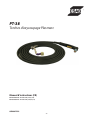
PT-38
Plasmarc Cutting Torches
Instruction Manual (EN)
Manuel d’instructions (FR)
P/N 0558006786 - PT-38 Torch, 25' (7.6 m)
P/N 0558006787 - PT-38 Torch, 50' (15.2 m)
0558007599
09/2009
Be sure this information reaches the operator.
You can get extra copies through your supplier.
caution
These INSTRUCTIONS are for experienced operators. If you are not fully familiar with the
principles of operation and safe practices for arc welding and cutting equipment, we urge
you to read our booklet, “Precautions and Safe Practices for Arc Welding, Cutting, and
Gouging,” Form 52-529. Do NOT permit untrained persons to install, operate, or maintain
this equipment. Do NOT attempt to install or operate this equipment until you have read
and fully understand these instructions. If you do not fully understand these instructions,
contact your supplier for further information. Be sure to read the Safety Precautions before installing or operating this equipment.
USER RESPONSIBILITY
This equipment will perform in conformity with the description thereof contained in this manual and accompanying labels and/or inserts when installed, operated, maintained and repaired in accordance with the instructions provided. This equipment must be checked periodically. Malfunctioning or poorly maintained equipment
should not be used. Parts that are broken, missing, worn, distorted or contaminated should be replaced immediately. Should such repair or replacement become necessary, the manufacturer recommends that a telephone
or written request for service advice be made to the Authorized Distributor from whom it was purchased.
This equipment or any of its parts should not be altered without the prior written approval of the manufacturer.
The user of this equipment shall have the sole responsibility for any malfunction which results from improper
use, faulty maintenance, damage, improper repair or alteration by anyone other than the manufacturer or a service facility designated by the manufacturer.
READ AND UNDERSTAND THE INSTRUCTION MANUAL BEFORE INSTALLING OR OPERATING.
PROTECT YOURSELF AND OTHERS!
2
TABLE OF CONTENTS
SECTION
TITLE
PAGE
English
....................................................................................................................................................5
French
..................................................................................................................................................29
3
4
PT-38
Plasmarc Cutting Torches
Instruction Manual (EN)
P/N 0558006786 - PT-38 Torch, 25' (7.6 m)
P/N 0558006787 - PT-38 Torch, 50' (15.2 m)
0558007599
5
Be sure this information reaches the operator.
You can get extra copies through your supplier.
caution
These INSTRUCTIONS are for experienced operators. If you are not fully familiar with the
principles of operation and safe practices for arc welding and cutting equipment, we urge
you to read our booklet, “Precautions and Safe Practices for Arc Welding, Cutting, and
Gouging,” Form 52-529. Do NOT permit untrained persons to install, operate, or maintain
this equipment. Do NOT attempt to install or operate this equipment until you have read
and fully understand these instructions. If you do not fully understand these instructions,
contact your supplier for further information. Be sure to read the Safety Precautions before installing or operating this equipment.
USER RESPONSIBILITY
This equipment will perform in conformity with the description thereof contained in this manual and accompanying labels and/or inserts when installed, operated, maintained and repaired in accordance with the instructions provided. This equipment must be checked periodically. Malfunctioning or poorly maintained equipment
should not be used. Parts that are broken, missing, worn, distorted or contaminated should be replaced immediately. Should such repair or replacement become necessary, the manufacturer recommends that a telephone
or written request for service advice be made to the Authorized Distributor from whom it was purchased.
This equipment or any of its parts should not be altered without the prior written approval of the manufacturer.
The user of this equipment shall have the sole responsibility for any malfunction which results from improper
use, faulty maintenance, damage, improper repair or alteration by anyone other than the manufacturer or a service facility designated by the manufacturer.
READ AND UNDERSTAND THE INSTRUCTION MANUAL BEFORE INSTALLING OR OPERATING.
PROTECT YOURSELF AND OTHERS!
6
TABLE OF CONTENTS
SECTION
TITLE
PAGE
SECTION 1SAFETY....................................................................................................................................................9
1.0
Safety Precautions..................................................................................................................................................................... 9
SECTION 2
DESCRIPTION........................................................................................................................................11
2.0 Description.................................................................................................................................................................................11
2.1
Torch Specifications.................................................................................................................................................................12
2.2
Optional Accessories...............................................................................................................................................................13
2.3
Spare Parts Kits..........................................................................................................................................................................13
2.4
Consumables Breakdown PC-1300/1600:.......................................................................................................................14
2.5
Consumables Breakdown PC-900:.....................................................................................................................................15
SECTION 3
INSTALLATION.......................................................................................................................................17
3.0
Installation..................................................................................................................................................................................17
3.1
Torch Installation......................................................................................................................................................................17
SECTION 4OPERATION............................................................................................................................................19
4.0
Cutting with the PT-38............................................................................................................................................................19
4.1
Stand-off Guide.........................................................................................................................................................................21
4.2
Drag Cutting 40 Amp..............................................................................................................................................................21
4.3
Gouging with the PT-38.........................................................................................................................................................22
4.4 Installing Consumables..........................................................................................................................................................22
4.5
Cut Data.......................................................................................................................................................................................23
4.6
Operation of Power Source...................................................................................................................................................23
SECTION 5
MAINTENANCE......................................................................................................................................53
5.0 General .......................................................................................................................................................................................53
5.1 Dirt or Contamination.............................................................................................................................................................53
5.2
Inspection, Cleaning and Replacement of Consumables..........................................................................................54
5.3
Disassembly / Assembly of Torch........................................................................................................................................56
5.4 Measuring Torch Gas Flows...................................................................................................................................................59
SECTION 6
REPLACEMENT PARTS...........................................................................................................................61
6.0
Replacement Parts...................................................................................................................................................................61
6.1
General .......................................................................................................................................................................................61
6.2
Ordering.......................................................................................................................................................................................61
Diagrams and Parts List..........................................................................................................................................................62
7
TABLE OF CONTENTS
8
section 1
safety precautions
1.0Safety Precautions
Users of ESAB welding and plasma cutting equipment have the ultimate responsibility for ensuring that
anyone who works on or near the equipment observes all the relevant safety precautions. Safety precautions
must meet the requirements that apply to this type of welding or plasma cutting equipment. The following
recommendations should be observed in addition to the standard regulations that apply to the workplace.
All work must be carried out by trained personnel well acquainted with the operation of the welding or plasma
cutting equipment. Incorrect operation of the equipment may lead to hazardous situations which can result in
injury to the operator and damage to the equipment.
1.
Anyone who uses welding or plasma cutting equipment must be familiar with:
- its operation
- location of emergency stops
- its function
- relevant safety precautions
- welding and / or plasma cutting
2. The operator must ensure that:
- no unauthorized person stationed within the working area of the equipment when it is started up.
- no one is unprotected when the arc is struck.
3. The workplace must:
- be suitable for the purpose
- be free from drafts
4. Personal safety equipment:
- Always wear recommended personal safety equipment, such as safety glasses, flame proof
clothing, safety gloves.
- Do not wear loose fitting items, such as scarves, bracelets, rings, etc., which could become
trapped or cause burns.
5.
General precautions:
- Make sure the return cable is connected securely.
- Work on high voltage equipment may only be carried out by a qualified electrician.
- Appropriate fire extinquishing equipment must be clearly marked and close at hand.
- Lubrication and maintenance must not be carried out on the equipment during operation.
Enclosure Class
The IP code indicates the enclosure class, i.e. the degree of protection against penetration by solid objects or
water. Protection is provided against touch with a finger, penetration of solid objects greater than 12mm and
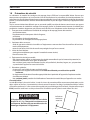
against spraying water up to 60 degrees from vertical. Equipment marked IP23S may be stored, but is not intended to be used outside during precipitation unless sheltered.
CAUTION
If equipment is placed on a surface that slopes
more than 15°, toppling over may occur. Personal
injury and / or significant damage to equipment is
possible.
9
Maximum
Tilt Allowed
15°
section 1
safety precautions
WARNING
WELDING AND PLASMA CUTTING CAN BE INJURIOUS TO YOURSELF AND
OTHERS. TAKE PRECAUTIONS WHEN WELDING OR CUTTING. ASK FOR
YOUR EMPLOYER’S SAFETY PRACTICES WHICH SHOULD BE BASED ON
MANUFACTURERS’ HAZARD DATA.
ELECTRIC SHOCK - Can kill.
- Install and earth (ground) the welding or plasma cutting unit in accordance with applicable standards.
- Do not touch live electrical parts or electrodes with bare skin, wet gloves or wet clothing.
- Insulate yourself from earth and the workpiece.
- Ensure your working stance is safe.
FUMES AND GASES - Can be dangerous to health.
- Keep your head out of the fumes.
- Use ventilation, extraction at the arc, or both, to take fumes and gases away from your breathing zone
and the general area.
ARC RAYS - Can injure eyes and burn skin.
- Protect your eyes and body. Use the correct welding / plasma cutting screen and filter lens and wear
protective clothing.
- Protect bystanders with suitable screens or curtains.
FIRE HAZARD
- Sparks (spatter) can cause fire. Make sure therefore that there are no inflammable materials nearby.
NOISE - Excessive noise can damage hearing.
- Protect your ears. Use earmuffs or other hearing protection.
- Warn bystanders of the risk.
MALFUNCTION - Call for expert assistance in the event of malfunction.
READ AND UNDERSTAND THE INSTRUCTION MANUAL BEFORE INSTALLING OR OPERATING.
PROTECT YOURSELF AND OTHERS!
CAUTION
This product is solely intended for plasma cutting. Any other use may
result in personal injury and / or equipment damage.
CAUTION
To avoid personal injury and/or equipment damage, lift using method and attachment points
shown here.
10
SECTION 2
WARNING
DESCRIPTION
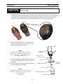
The plasma arc cutting process employs high voltages.
Contact with "live" parts of the torch and machine must
be avoided. Also, the improper use of any of the gases employed can present a safety hazard. Before beginning operation with the PT-38 torch, refer to the Safety Precautions and operating instructions in the appropriate power
source instruction manual.
Using the pt-38 torch on any unit not equipped with a mating safety interlock circuit may expose operator to unexpected high voltage.
2.0
Description
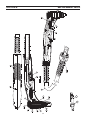
The PT-38 is a manual torch with a 90° head designed for use with several plasma arc cutting packages using clean, dry air
as the plasma gas. The service line lengths available with the PT-38 torch are 25 feet (7.6 m) and 50 feet (15.2 m). The PT-38
torch is rated to operate at a maximum of 90 amperes at 100% duty cycle.
This manual is intended to provide the operator with all the information required to assemble, operate, and repair the PT-38
Plasma Arc Cutting Torch. For additional safety precautions, process instructions, and system troubleshooting; refer to the
appropriate instruction manual for your Plasma Arc Cutting Package.
Designed for superior cutting performance and ease of handling, the PT-38 produces clean, exceptionally high quality
cuts.
•
•
•
•
•
•
•
•
Most compact 90 amp torch on the market
Excellent cutting capacity - Cuts 1-1/2 in. (38 mm); severs 1-3/4 in. (45 mm)
Uses shop air, cylinder air for superior versatility
Pilot arc starting - even starts through paint
Choice of 25 ft (7.6 m). or 50 ft (15.2 m) line length
Excellent consumable life
Parts in place design
One-year warranty
11
SECTION 2
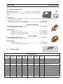
2.1
DESCRIPTION
Torch Specifications:
Cuts ..................................................................................................................................................1-1/2 in. (38 mm); severs 1-3/4 in. (45 mm)
Current Capacity..................................................................................................................................................... 90 amps @ 100% duty cycle
Nominal Flow Rate............................................................................................................................ 400 cfh @ 80 psig (189 l/min @ 5.5 bar)
Length of Service Lines........................................................................................................................................ 25 ft (7.6 m) or 50 ft (15.2 m)
Dimensions
Overall Length.................................................................................................................................................................................8.2 in. (208 mm)
Length of Head..................................................................................................................................................................................3.0 in. (76 mm)
PT-38 Torch, 25' (7.6 m)........................................................................................................................................................................ 0558006786
PT-38 Torch, 50' (15.2 m)...................................................................................................................................................................... 0558006787
Torches and torch body assemblies are supplied without gas baffle, electrode, nozzle, and retaining/shield cup. Order complete spare parts kits or individual components shown in PT-38 Spare Parts Kits or Consumables Breakdown section.
Compatible ESAB Consoles:
Powercut-1300:
208-230/460 V Console.............................................0558007220
208-230/460 V Console BL ................................... 0558007220F
400 V CE Console.........................................................0558007224
400 V Console...............................................................0558007634
460 V Console...............................................................0558008320
575 V Console BL ........................................................0558007227
Powercut-1600:
208-230/460 V Console.............................................0558007230
208-230/460 V Console BL ................................... 0558007230F
400 V CE Console.........................................................0558007234
400 V Console...............................................................0558007636
460 V Console...............................................................0558008323
575 V Console BL ........................................................0558007237
Powercut-900:
208/230 V Console.......................................................0558008120
208/230 V Console BL.............................................. 0558008120F
230 V CE Console..........................................................0558008123
400 V CE Console..........................................................0558008135
400 V Console................................................................0558008133
460 V Console................................................................0558008127
575 V Console BL...........................................................0558008131
12
SECTION 2
DESCRIPTION
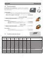
2.2Optional Accessories:
Gas Flow Measuring Kit ..................................... p/n 19765 ("CE" units - 0558000739)
Valuable troubleshooting tool allows measurement of the actual air flow through
the torch.
Torch Guide Kit:
This complete kit, in a rugged plastic carrying case, includes attachments for circle and straight line cutting on
ferrous and non-ferrous metals.
Deluxe, 1-3/4" - 42" (44.5 mm - 106 cm) Radius.........................................................p/n 0558003258
Basic, 1-3/4” - 28” (44.5 mm - 71 cm) Radius .............................................................p/n 0558002675
Powercut-1300/1600
Stand-off Guide Assembly 90 Amp....................................................................................p/n 0558006614
Use to maintain constant stand-off distance.
Gouging 90 Amp:
• Gouging Nozzle 90 Amp........................................................................................p/n 0558007681
• Gouging Heat Shield Assembly 90 Amp..........................................................p/n 0558008186
• *Note: Must use 90/100 Amp Gas Baffle........................................................ p/n 0558004870
Powercut-900
Stand-off Guide Assembly 60 Amp....................................................................................p/n 0558008592
Use to maintain constant stand-off distance.
Gouging 60 Amp:
• Gouging Nozzle 60 Amp....................................................................................... p/n 0558008588
• Gouging Heat Shield Assembly 60 Amp..........................................................p/n 0558008591
2.3Spare Parts Kits:
PT-38 Spare Parts Kits
0558007640
90 AMP
PC-1600 CE
0558007639
90 AMP
PC-1600
0558007642
70 AMP
PC-1300 CE
0558007641
70 AMP
PC-1300
0558008419
60 AMP
PC-900 CE
0558008418
60 AMP
PC-900
Part
Number
Description
3
3
3
3
3
3
0558005220
ELECTRODE
1
1
1
1
1
1
0558005217
GAS BAFFLE 30-70A
1
1
-
-
-
-
0558004870
GAS BAFFLE 90/100A
-
-
-
-
3
3
0558008417
NOZZLE 60 AMP
-
-
4
4
-
-
0558005219
NOZZLE 70 AMP
4
4
-
-
-
-
0558007680
NOZZLE 90 AMP
1
1
1
1
-
-
0558007682
NOZZLE DRAG 40 AMP
-
1
-
1
-
1
0558007549
RETAINING / SHIELD CUP
1
-
1
-
1
-
0558008094
RETAINING / SHIELD CUP LONG
3
3
3
3
3
3
2064062
O-RING .301ID .070W Nitrile
1
1
1
1
1
1
17672
GREASE SILICON DOW DC-111 (1/4 oz)
1
1
1
1
1
1
0558001379
FUSE MIDGET SLO-BLO 2A 600V
13
90A
0558008094
0558007680
0558005220
0558004870
O-RING
85W51
SECTION 2
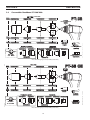
DESCRIPTION
2.4Consumables Breakdown PC-1300/1600:
0558008094
0558005219
0558007680
0558005220
0558005220
0558007682
0558005217
0558004870
0558005220
STAND-OFF�GUIDE
0558006613
0558006611
0558006601
0558005217
O-RING
JOINT TORIQUE
85W51
GREASE
17672
GOUGING
0558006611 0558007681 0558004870
80 PSI
5.5 BAR
PT-38
O-RING
2064062
FUSE�2A�600V
0558001379
70A
0558007549
0558005219
0558006614
40A
0558007549
0558007682
0558005220
0558008186 0558005217
0558005220
STAND-OFF�GUIDE
GUIDE DE HAUTEUR
0558006613
0558006611
0558006601
0558005217
GREASE
GRAIS SE
17672
GOUGING
GOUGEAGE
0558006611 0558007681 0558004870
80 PSI
5.5 BAR
0558006614
O-RING
JOINT TORIQUE
2064062
FUSE�2A�600V
FUSIBLE 2A 600V
0558001379
0558008186
P/N 0558954137-C 8/08
40A
0558008094
0558007549
P/N 0558954090-C 8/08
CUTTING�/ COUPAGE
70A
90A
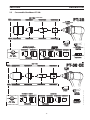
*Note: When Gouging use 90 amp Baffle (0558004870)
CUTTING
90A
0558008094
0558007680
0558005220
0558004870
70A
0558008094
0558005219
0558005220
0558005217
40A
0558008094
0558007682
0558005220
0558005217
STAND-OFF�GUIDE
0558006613
0558006611
0558006601
GREASE
17672
GOUGING
0558006611 0558007681 0558004870
80 PSI
5.5 BAR
O-RING
2064062
FUSE�2A�600V
0558001379
0558006614
0558008186
*Note: When Gouging use 90 amp Baffle (0558004870)
14
P/N 0558954137-C 8/08
O-RING
85W51
SECTION 2
DESCRIPTION
2.5Consumables Breakdown PC-900:
CUTTING�/ COUPAGE
0558008417
0558005220
0558005217
O-RING
JOINT TORIQUE
85W51
40A
0558007549
0558007682
0558005220
PT-38
0558005217
GREASE
GRAIS SE
17672
STAND-OFF�GUIDE
GUIDE DE HAUTEUR
0558008590
0558006611
GOUGING
GOUGEAGE
0558006611 0558008588 0558005217
0558006602
80 PSI
5.5 BAR
0558008592
O-RING
JOINT TORIQUE
2064062
FUSE�2A�600V
FUSIBLE 2A 600V
0558001379
0558008591
P/N 0558954165-OR 9/08
60A
0558007549
CUTTING
60A
0558008417
0558008094
0558005220
0558005217
O-RING
85W51
0558005220
0558005220
0558005217
0558005217
O-RING
JOINT TORIQUE
85W51
GREASE
17672
STAND-OFF�GUIDE
0558008590
0558006611
O-RING
2064062
GOUGING
0558006602
0558006611
0558008588 0558005217
80 PSI
5.5 BAR
40A
0558007549
PT-38
FUSE�2A�600V
0558001379
0558008592
0558007682
0558005220
0558008591
0558005217
GREASE
GRAIS SE
17672
STAND-OFF�GUIDE
GUIDE DE HAUTEUR
0558008590
0558006611
15
0558006602
GOUGING
GOUGEAGE
0558006611 0558008588 0558005217
O-RING
JOINT TORIQUE
2064062
P/N 0558954166-A 1/09
CUTTING�/ COUPAGE
0558007682
0558008417
954165-OR 9/08
0558008094
40A
60A 0558007549
SECTION 2
DESCRIPTION
16
SECTION 3
WARNING
3.0
Installation
3.1
Torch Installation
INSTALLATION
Make sure power switch on console is in OFF position and
primary input power is de-energized.
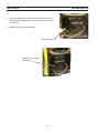
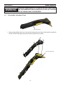
1. Open torch lead access door on the front panel of the Powercut-1300/1600.
Torch Lead
Access
Door
2. Connect the torch cable male receptacle to the panel receptacle.
Check orientation of the sockets to ensure a correct fit.
Panel Receptacle
Torch Cable Male
Receptacle
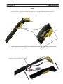
3. Connect the air hose to the quick-connect fitting. Place the strain relief in the square cutout in the front of
the console. Line up the groove of the strain relief with the half square cutout area.
square cutout
strain relief
Air Hose quick-connect fitting
17
SECTION 3
INSTALLATION
4. Insert work cable into receptacle on the front of the console and
turn clockwise until secure.
5. Replace torch lead access door.
Work Cable
Torch Lead Access Door
18
SECTION 4OPERATION
danger
DO NOT use oxygen with this torch! A hazardous fire may
result.
WARNING
ELECTRIC SHOCK can kill.
• Do NOT operate the unit with the cover removed.
• Do NOT apply power to the unit while holding or carrying the unit.
• Do NOT touch any torch parts forward of the torch
handle (nozzle, heat shield, electrode, etc.) with power
switch on.
4.0Cutting with the PT-38
Use the following procedures to cut with the PT-38 torch.
1. Make sure that the wall disconnect switch is on. Turn on the Power Switch to the cutting power source console.
2. Set Pressure Regulator to 80 psig (5.5 bar).
3. PC-1300/1600: Hold the torch nozzle approximately 1/8 in. to 1/4 in. (3.2 mm - 6.4 mm) above the work
and tilted at about 5 - 15°. This reduces the chance of spatter entering the nozzle. If the PT-38's 90A standoff guide is being used, the distance between nozzle and work piece will be approximately 1/4 in. (6.4 mm).
PC-900: Hold the torch nozzle approximately 1/8 in. to 3/16 in. (3.2 mm - 4.8 mm) above the work and tilted at
about 5 - 15°. This reduces the chance of spatter entering the nozzle. If the PT-38's 60A standoff guide is being
used, the distance between nozzle and work piece will be approximately 1/8 in. (3.2 mm).
4. Depress the torch switch. Air should flow from the torch nozzle.
5. Two seconds after depressing the torch switch, the pilot arc should start. The main arc should immediately follow, allowing the cut to begin. If using the trigger LOCK mode, torch switch may be released after establishing
the cutting arc.
6. After starting the cut, the torch should be maintained at a 5 - 15° forward angle (Figure 4-1). This angle is especially useful in helping to create a "drop" cut. When not using the standoff guide, the nozzle should be held
approximately, PC-1300/1600: 1/8 - 1/4 in. (3.2 mm - 6.4 mm), PC-900: 1/8 - 3/16 in. (3.2 mm - 4.8 mm) from the
work.
PC-900/1300/1600
5˚ to 15˚
PC-1300/1600
PC-900
IMPORTANT!!!
IMPORTANT!!!
Maintain Proper
Stand-Off Distance
Maintain Proper
Stand-Off Distance
Power Output increases
with Stand-off Distance!
Power Output increases
with Stand-off Distance!
1/8 in. to 1/4 in.
(3.2 mm - 6.4 mm)
1/8 in. to 3/16 in.
(3.2 mm - 4.8 mm)
CUT DIRECTION
Figure 4-1. Proper Torch Angle
Figure 4-2. Stand-off vs. Power Output
19
SECTION 4OPERATION
WARNING
ARC RAYS can burn eyes and skin;
NOISE can damage hearing.
• Wear welding helmet with No. 6 or 7 lens shade.
• Wear eye, ear, and body protection.
2. WHEN THE ARC BREAKS THROUGH THE WORK, BRING
THE TORCH TO AN UPRIGHT POSITION AND PROCEED
TO CUT.
1. TO START A PIERCE, TILT THE TORCH TO PREVENT MOLTEN
MATERIAL FROM COMING BACK AGAINST AND DAMAGING
THE TORCH.
Figure 4-3. Piercing & Cutting Techniques using the PT-38
20
SECTION 4OPERATION
WARNING
Drag cutting, even with lower current levels may significantly reduce the life of torch consumables. Attempting
to Drag Cut with higher currents greater than 40 amps
may cause immediate catastrophic consumable damage.
4.1Stand-off Guide
Use to maintain a constant stand-off distance. Attach optional stand-off guide assembly by removing the retaining/shield
cup and installing the stand-off guide assembly.
Stand-off guide
assembly
Guide against
straight edge or
free-hand cut.
Figure 4-4. Installation and Operation of Stand-off Guide
4.2
Drag Cutting 40 Amp
For cutting thin material, under 3/8" (9 mm), insert low current gas baffle, electrode, 40 amp drag nozzle, and standard
retaining/shield cup. Set current level to 40 amps and begin cutting.
Gas Baffle (30-70 Amp)
Electrode
40 Amp Drag Nozzle
Retaining/Shield Cup
21
SECTION 4OPERATION
4.3Gouging with the PT-38
PC-1300/1600: Insert high current gas baffle, electrode, 90 amp gouge nozzle, and 90 amp gouging heatshield assembly.
Operating parameters are 60 - 80 psi (4.1 - 5.5 bar) and 70 - 90 amps. Air pressure and current can be varied within these
ranges to produce desired metal removal rate and groove profile.
PC-900: Insert standard gas baffle, electrode, 60 amp gouge nozzle, and 60 amp gouging heatshield assembly. Operating
parameters are 60 - 80 psi (4.1 - 5.5 bar) and 40 - 60 amps. Air pressure and current can be varied within these ranges to
produce desired metal removal rate and groove profile.
Gouge Nozzle 90 Amp - PC-1300/1600
60 Amp - PC-900
Gas Baffle 90 Amp - PC-1300/1600
Gouging Heatshield Assembly
Electrode
90 Amp - PC-1300/1600
60 Amp - PC-900
Gas Baffle 60 Amp - PC-900
4.4 Installing Consumables
Tests have shown that with proper use of the torch within rated operating conditions (especially arc current and gas flow
rate), the torch consumable parts do not become loose if they are firmly installed. Torch damage and overheating can be
caused by loose parts.
A. Tighten electrode and retaining/shield cup fully at each consumable change or inspection.
B. Check consumable tightness at beginning of each work period, even if everything was working normally at the end of
the previous period.
Note:
Ensure that the electrode/torch body seat
and piston are clean and free of dust or
dirt. Debris may prevent mating surfaces
from having solid contact.
Note:
Firm tightening of the electrode by hand is
sufficient, the use of tools such as wrenches or pliers is not required or
recommended.
Torch Body
Assembly
Electrode/Torch
Body Seat
Piston
Gas Baffle (90A)
Note:
Torch damage and overheating can be
caused by loose parts. Arc tracking indicates loose parts. Make sure retaining
cup is tightened fully. Parts damaged by
arcing will cause destruction of torch and
must be replaced.
Electrode
Retaining/Shield Cup
Nozzle
22
Gas Baffle
(30-70A)
SECTION 4OPERATION
4.5Cut Data
Use the following pages to adjust your torch settings to obtain optimum cutting performance.
danger
DO NOT use oxygen with this torch! A hazardous fire may
result.
4.6Operation of Power Source
For operation of the power source, refer to Powercut-1300/1600 power source instruction manual.
23
SECTION 4OPERATION
PT-38
Powercut-1300/1600
Plasma System Process Data
Description
Part Number
Electrode
0558005220
Nozzle
0558007682
Gas Baffle
0558005217
Retaining/Shield Cup
0558007549
40 Amperes
Carbon Steel
Material
Thickness
in(mm)
.06 (1.5)
.125 (3.2)
.25 (6.4)
.50 (12.7)
Stand-off
Initial Height
in(mm)
.06 (1.5) .125 (3.2)
.06 (1.5) .125 (3.2)
.06 (1.5) .125 (3.2)
.06 (1.5) .125 (3.2)
Air
Pressure
PSI (BAR)
80 (5.5)
80 (5.5)
80 (5.5)
80 (5.5)
IPM
360
190
62
18
MM/MIN
9144
4826
1575
457
Travel
Speed
40 Amperes
Aluminum
Material
Thickness
in(mm)
.06 (1.5)
.125 (3.2)
.25 (6.4)
.50 (12.7)
Stand-off
Initial Height
in(mm)
.06 (1.5) .125 (3.2)
.06 (1.5) .125 (3.2)
.06 (1.5) .125 (3.2)
.06 (1.5) .125 (3.2)
Air
Pressure
PSI (BAR)
80 (5.5)
80 (5.5)
80 (5.5)
80 (5.5)
IPM
375
150
48
16
MM/MIN
9525
3810
1219
406
Travel
Speed
40 Amperes
Stainless Steel
Material
Thickness
in(mm)
.06 (1.5)
.125 (3.2)
.25 (6.4)
.50 (12.7)
Stand-off
Initial Height
in(mm)
.06 (1.5) .125 (3.2)
.06 (1.5) .125 (3.2)
.06 (1.5) .125 (3.2)
.06 (1.5) .125 (3.2)
Air
Pressure
PSI (BAR)
80 (5.5)
80 (5.5)
80 (5.5)
80 (5.5)
IPM
352
130
26
8
MM/MIN
8941
3302
660.4
203
Travel
Speed
24
SECTION 4OPERATION
PT-38
Powercut-900
Plasma System Process Data
Description
Part Number
Electrode
0558005220
Nozzle
0558008417
Gas Baffle
0558005217
Retaining/Shield Cup
0558007549
60 Amperes
Carbon Steel
Material
Thickness
in(mm)
.25 (6.4)
.50 (12.7)
.75 (19.1)
1.0 (25.4)
Stand-off
Initial Height
in(mm)
.125 (3.2)
.125 (3.2)
.125 (3.2)
.125 (3.2)
Air
Pressure
PSI (BAR)
80 (5.5)
80 (5.5)
80 (5.5)
80 (5.5)
IPM
117
35
18
8
MM/MIN
2971
889
457.2
203.2
Travel
Speed
60 Amperes
Aluminum
Material
Thickness
in(mm)
.25 (6.4)
.50 (12.7)
.75 (19.1)
1.0 (25.4)
Stand-off
Initial Height
in(mm)
.188 (4.78)
.188 (4.78)
.188 (4.78)
.188 (4.78)
Air
Pressure
PSI (BAR)
80 (5.5)
80 (5.5)
80 (5.5)
80 (5.5)
IPM
105
46
19
14
MM/MIN
2667
1168.4
482.6
355.6
Travel
Speed
60 Amperes
Stainless Steel
Material
Thickness
in(mm)
.25 (6.4)
.50 (12.7)
.75 (19.1)
1.0 (25.4)
Stand-off
Initial Height
in(mm)
.188 (4.78)
.188 (4.78)
.188 (4.78)
.188 (4.78)
Air
Pressure
PSI (BAR)
80 (5.5)
80 (5.5)
80 (5.5)
80 (5.5)
IPM
82
25
12
7
MM/MIN
2082.8
635
304.8
177.8
Travel
Speed
25
SECTION 4OPERATION
PT-38
Powercut-1300/1600
Plasma System Process Data
Description
Part Number
Electrode
0558005220
Nozzle
0558005219
Gas Baffle
0558005217
Retaining/Shield Cup
0558007549
70 Amperes
Carbon Steel
Material
Thickness
in(mm)
.25 (6.4)
.50 (12.7)
.75 (19.1)
1.0 (25.4)
1.25 (31.8)
Stand-off
Initial Height
in(mm)
.125 (3.2)
.125 (3.2)
.125 (3.2)
.125 (3.2)
.125 (3.2)
Air
Pressure
PSI (BAR)
80 (5.5)
80 (5.5)
80 (5.5)
80 (5.5)
80 (5.5)
IPM
150
50
26
12
5
MM/MIN
3810
1270
660.4
305
127
Travel
Speed
70 Amperes
Aluminum
Material
Thickness
in(mm)
.25 (6.4)
.50 (12.7)
.75 (19.1)
1.0 (25.4)
1.25 (31.8)
Stand-off
Initial Height
in(mm)
.188 (4.78)
.188 (4.78)
.188 (4.78)
.188 (4.78)
.188 (4.78)
Air
Pressure
PSI (BAR)
80 (5.5)
80 (5.5)
80 (5.5)
80 (5.5)
80 (5.5)
IPM
140
66
28
20
11
MM/MIN
3556
1676.4
711.2
508
279.4
Travel
Speed
70 Amperes
Stainless Steel
Material
Thickness
in(mm)
.25 (6.4)
.50 (12.7)
.75 (19.1)
1.0 (25.4)
1.25 (31.8)
Stand-off
Initial Height
in(mm)
.188 (4.78)
.188 (4.78)
.188 (4.78)
.188 (4.78)
.188 (4.78)
Air
Pressure
PSI (BAR)
80 (5.5)
80 (5.5)
80 (5.5)
80 (5.5)
80 (5.5)
IPM
110
36
17
11
6
MM/MIN
2794
914.4
431.8
279.4
152.4
Travel
Speed
26
section 4
operation
PT-38
Description
Part Number
Electrode
0558005220
Nozzle
0558007680
Gas Baffle
0558004870
Retaining/Shield Cup
0558007549
Powercut-1300/1600
Plasma System Process Data
90 Amperes
Carbon Steel
Material
Thickness
in(mm)
.25 (6.4)
.50 (12.7)
.75 (19.1)
1.0 (25.4)
1.5 (38.1)
Stand-off
Initial Height
in(mm)
.125 (3.8)
.125 (3.8)
.125 (3.8)
.125 (3.8)
.125 (3.8)
Air
Pressure
PSI (BAR)
80 (5.5)
80 (5.5)
80 (5.5)
80 (5.5)
80 (5.5)
IPM
160
60
29
19
8
MM/MIN
4064
1524
737
483
203
Travel
Speed
90 Amperes
Aluminum
Material
Thickness
in(mm)
.25 (6.4)
.50 (12.7)
.75 (19.1)
1.0 (25.4)
1.5 (38.1)
Stand-off
Initial Height
in(mm)
.250 (6.4)
.250 (6.4)
.250 (6.4)
.250 (6.4)
.250 (6.4)
Air
Pressure
PSI (BAR)
80 (5.5)
80 (5.5)
80 (5.5)
80 (5.5)
80 (5.5)
IPM
188
76
52
27
12
MM/MIN
4775
1930
1321
686
305
Travel
Speed
90 Amperes
Stainless Steel
Material
Thickness
in(mm)
.25 (6.4)
.50 (12.7)
.75 (19.1)
1.0 (25.4)
1.5 (38.1)
Stand-off
Initial Height
in(mm)
.125 (3.8)
.125 (3.8)
.250 (6.4)
.250 (6.4)
.250 (6.4)
Air
Pressure
PSI (BAR)
80 (5.5)
80 (5.5)
80 (5.5)
80 (5.5)
80 (5.5)
IPM
126
48
30
15
8
MM/MIN
3200
1219
762
381
203
Travel
Speed
27
SECTION 4OPERATION
28
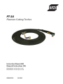
PT-38
Torches d’oxycoupage Plasmarc
Manuel d’instructions (FR)
P/N 0558006786 - PT-38 Torche, 25' (7,6 m)
P/N 0558006787 - PT-38 Torche, 50' (15,2 m)
0558007599
29
ASSUREZ-VOUS QUE CETTE INFORMATION EST DISTRIBUÉE À L'OPÉRATEUR.
VOUS POUVEZ OBTENIR DES COPIES SUPPLÉMENTAIRES CHEZ VOTRE FOURNISSEUR.
aTTENTION
Les INSTRUCTIONS suivantes sont destinées aux opérateurs qualifiés seulement. Si
vous n’avez pas une connaissance approfondie des principes de fonctionnement et des
règles de sécurité pour le soudage à l’arc et l’équipement de coupage, nous vous
suggérons de lire notre brochure « Precautions and Safe Practices for Arc Welding, Cutting and Gouging, » Formulaire 52-529. Ne permettez PAS aux personnes non qualifiées
d’installer, d’opérer ou de faire l’entretien de cet équipement. Ne tentez PAS d’installer
ou d’opérer cet équipement avant de lire et de bien comprendre ces instructions. Si vous
ne comprenez pas bien les instructions, communiquez avec votre fournisseur pour plus
de renseignements. Assurez-vous de lire les Règles de Sécurité avant d’installer ou
d’opérer cet équipement.
RESPONSABILITÉS DE L'UTILISATEUR
Cet équipement opérera conformément à la description contenue dans ce manuel, les étiquettes
d’accompagnement et/ou les feuillets d’information si l’équipement est installé, opéré, entretenu
et réparé selon les instructions fournies. Vous devez faire une vérification périodique de
l’équipement. Ne jamais utiliser un équipement qui ne fonctionne pas bien ou n’est pas bien
entretenu. Les pièces qui sont brisées, usées, déformées ou contaminées doivent être remplacées
immédiatement. Dans le cas où une réparation ou un remplacement est nécessaire, il est
recommandé par le fabricant de faire une demande de conseil de service écrite ou par téléphone
chez le Distributeur Autorisé de votre équipement.
Cet équipement ou ses pièces ne doivent pas être modifiés sans permission préalable écrite par
le fabricant. L’utilisateur de l’équipement sera le seul responsable de toute défaillance résultant
d’une utilisation incorrecte, un entretien fautif, des dommages, une réparation incorrecte ou une
modification par une personne autre que le fabricant ou un centre de service désigné par le
fabricant.
ASSUREZ-VOUS DE LIRE ET DE COMPRENDRE LE MANUEL D'UTILISATION AVANT
D'INSTALLER OU D'OPÉRER L'UNITÉ.
PROTÉGEZ-VOUS ET LES AUTRES !
30
TABLE DES MATIÈRES
SECTION
SECTION 1
1.0
SECTION 2
2.0 2.1
2.2
2.3
2.4
2.5
SECTION 3
3.0
3.1
SECTION 4
4.0
4.1
4.2
4.3
4.4 4.5
4.6
SECTION 5
5.0 5.1 5.2
5.3
5.4 SECTION 6
6.0
6.1
6.2
TITRE
PAGE
Sécurité...............................................................................................................................................33
Précautions de sécurité..........................................................................................................................................................33
DESCRIPTION........................................................................................................................................35
Description.................................................................................................................................................................................35
Caractéristiques de la torche :..............................................................................................................................................36
Accessoires en option :...........................................................................................................................................................37
Ensembles de pièces de rechange :...................................................................................................................................37
Analyse des consommables - PC-1300/1600 :...............................................................................................................38
Analyse des consommables - PC-900 :.............................................................................................................................39
INSTALLATION.......................................................................................................................................41
Installation..................................................................................................................................................................................41
Installation de la torche..........................................................................................................................................................41
FONCTIONNEMENT...............................................................................................................................43
Couper avec le PT-38...............................................................................................................................................................43
Guide de hauteur......................................................................................................................................................................45
Coupe en glissement 40 A....................................................................................................................................................45
Gougeage avec le PT-38.........................................................................................................................................................46
Installation des consommables...........................................................................................................................................46
Données de coupe...................................................................................................................................................................47
Fonctionnement de la source d’énergie..........................................................................................................................47
ENTRETIEN.............................................................................................................................................53
General .......................................................................................................................................................................................53
Dirt or Contamination.............................................................................................................................................................53
Inspection, Cleaning and Replacement of Consumables..........................................................................................54
Disassembly / Assembly of Torch........................................................................................................................................56
Measuring Torch Gas Flows...................................................................................................................................................59
PIÈCES DE RECHANGE...........................................................................................................................53
Replacement Parts...................................................................................................................................................................61
General .......................................................................................................................................................................................61
Ordering.......................................................................................................................................................................................61
Diagrammes et liste des pièces...........................................................................................................................................62
31
TABLE DES MATIÈRES
32
section 1précautions de sécurité
1.0
Précautions de sécurité
Les utilisateurs du matériel de soudage et de coupage plasma ESAB ont la responsabilité ultime d'assurer que
toute personne qui opère ou qui se trouve dans l'aire de travail observe les précautions de sécurité pertinentes. Les
précautions de sécurité doivent répondre aux exigences applicables à ce type de matériel de soudage ou de coupage
plasma. Les recommandations suivantes doivent être observées en plus des règles standard qui s'appliquent au lieu
de travail.
Tous les travaux doivent être effectués par un personnel qualifié possédant de bonnes connaissances par rapport
au fonctionnement du matériel de soudage et de coupage plasma. Un fontionnement incorrect du matériel peut
produire des situations dangereuses qui peuvent causer des blessures à l'opérateur ou des dommages au matériel.
1.
Toute personne travaillant avec le matériel de soudage ou de coupage plasma doit connaître :
- son fonctionnement;
- l'emplacement des interrupteurs d'arrêt d'urgence;
- sa fonction;
- les précautions de sécurité pertinentes;
- les procédures de soudage et/ou de coupage plasma.
2. L'opérateur doit assurer que :
- seules les personnes autorisées à travailler sur l'équipement se trouvent dans l'aire de travail lors de la mise en marche de l'équipement;
- toutes les personnes dans l'aire de travail sont protégées lorsque l'arc est amorcé.
3. Le lieu de travail doit être :
- aménagé convenablement pour acquérir le matériel en toute sécurité;
- libre de courants d'air.
4. Équipement de sécurité personnelle
- Vous devez toujours utiliser un équipement de sécurité convenable tels que les lunettes de protection, les vêtement ininflammables et des gants de protection.
- Vous ne devez jamais porter de vêtements amples, tels que foulards, bracelets, bagues, etc., qui pourraient se prendre dans l'appareil ou causer des brûlures.
5. Précautions générales :
- Assurez-vous que le câble de retour est bien branché.
- La réparation d'un équipement de haute tension doit être effectuée par un électricien qualifié seulement.
- Un équipement d'extinction d'incendie approprié doit être à proximité de l'appareil et l'emplacement doit être clairement indiqué.
- Vous ne devez jamais procéder à la lubrification ou l'entretien du matériel lorsque l'appareil est en marche.
Classe de boîtier
Le code IP indique la classe du boîtier, à savoir le niveau de protection offert contre toute pénétration par des
objets solides ou de l’eau. La protection est fournie contre le contact d’un doigt, la pénétration d’objets solides
d’une taille supérieure à 12 mm et contre l’eau pulvérisée jusqu’à 60 degrés de la verticale. L’équipement marqué
IP23S peut être stocké mais ne doit pas être utilisé à l’extérieur quand il pleut à moins d’être sous abri.
ATTENTION
Si l’équipement est placé sur une surface inclinée
de plus de 15°, il y a danger de basculement et en
conséquence, des blessures personnelles et/ou des
dommages importants à l’équipement.
Inclinaison
maximum
autorisée
15°
33
section 1
PRÉCAUTIONS DE SÉCURITÉ
AVERTISSEMENT
LE SOUDAGE ET LE COUPAGE À L'ARC PEUVENT CAUSER DES
BLESSURES À L'OPÉRATEUR OU LES AUTRES PERSONNES
SE TROUVANT DANS L'AIRE DE TRAVAIL. ASSUREZ-VOUS
DE PRENDRE TOUTES LES PRÉCAUTIONS NÉCESSAIRES
LORS D'UNE OPÉRATION DE SOUDAGE OU DE COUPAGE.
DEMANDEZ À VOTRE EMPLOYEUR UNE COPIE DES MESURES
DE SÉCURITÉ QUI DOIVENT ÊTRE ÉLABORÉES À PARTIR DES
DONNÉES DES RISQUE DU FABRICANT.
CHOC ÉLECTRIQUE - peut être mortel.
- Assurez-vous que l'unité de soudage ou de coupage plasma est installée et mise à la terre conformément aux normes applicables.
- Ne touchez pas aux pièces électriques sous tension ou les électrodes si vos mains ne sont pas bien protégées ou si vos gants ou vos vêtements sont humides.
- Assurez-vous que votre corps est bien isolé de la mise à la terre et de la pièce à traiter.
- Assurez-vous que votre position de travail est sécure.
VAPEURS ET GAZ - peuvent être danereux pour la santé.
- Gardez votre tête éloignée des vapeurs.
- Utilisez un système de ventilation et/ou d'extraction à l'arc pour évacuer les vapeurs et les gaz de votre zone respiratoire.
RAYONS DE L'ARC - peuvent endommager la vue ou brûler la peau.
- Protégez vos yeux et votre corps. Utilisez un écran de soudage/coupage plasma convenable équipé de lentilles teintées et portez des vêtements de protection.
- Protégez les personnes se trouvant dans l'aire de travail à l'aide d'un écran ou d'un rideau protecteur convenable.
RISQUE D'INCENDIE
- Les étincelles (projections) peuvent causer un incendie. Assurez-vous qu'il n'y a pas de matériel inflammable à proximité de l'appareil.
BRUIT - un bruit excessif peut endommager la capacité auditive.
- Protégez vos oreilles. Utilisez des protecteurs d'oreilles ou un autre type de protection auditive.
- Avertissez les personnes se trouvant dans l'aire de travail de ce risque.
FONCTIONNEMENT DÉFECTUEUX - Dans le cas d'un fonctionnement défectueux demandez l'aide d'une personne qualifiée.
ASSUREZ-VOUS DE LIRE ET DE COMPRENDRE LE MANUEL D'UTILISATION AVANT
D'INSTALLER OU D'OPÉRER L'UNITÉ. PROTÉGEZ-VOUS ET LES AUTRES !
ATTENTION
Ce produit est uniquement destiné à la découpe du plasma. Toute autre
utilisation peut entraîner des blessures ou endommager l’équipement.
ATTENTION
Pour éviter toute blessure personnelle et/ou endommagement à l’équipement, soulever à l’aide
de la méthode et des points d’attache indiqués ici.
34
SECTION 2
MISE EN GARDE
DESCRIPTION
LE PROCÉDÉ DE COUPAGE À L’ARC PLASMA UTILISE DE LA HAUTE TENSION.
TOUT CONTACT AVEC DES PARTIES « ACTIVES » DE LA TORCHE ET DE LA
MACHINE DOIT ÊTRE ÉVITÉ. AUSSI, LA MAUVAISE UTILISATION DE TOUT GAZ
UTILISÉ PEUT PRÉSENTER UNE SITUATION DANGEREUSE. AVANT DE METTRE
EN MARCHE LA TORCHE PT-38, RÉFÉREZ-VOUS AUX MESURES DE SÉCURITÉ
ET AU MODE D’EMPLOI DANS LE MANUEL D’INSTRUCTIONS SUR LA SOURCE
D’ALIMENTATION APPROPRIÉE.
L’UTILISATION DE LA TORCHE PT-38 SUR TOUTE UNITÉ NON ÉQUIPÉE
D’UN CIRCUIT DE MATAGE À BLOCAGE DE SÉCURITÉ RISQUE D’EXPOSER
L’UTILISATEUR À UNE HAUTE TENSION INATTENDUE.
2.0
Description
Le PT-38 est une torche manuelle avec une tête de 90° conçue pour être utilisée avec plusieurs ensembles de coupage à l’arc
plasma utilisant de l’air propre et sec comme gaz pour le plasma. Les longueurs de branchement disponibles avec la torche
PT-38 sont 25 pieds (7,6 m) et 50 pieds (15,2 m). La torche PT-38 est cotée pour fonctionner à un maximum de 90 ampères
avec un cycle d’utilisation de 100%.
Ce manuel a pour but de fournir à l’utilisateur tous les renseignements nécessaires pour assembler, assurer le fonctionnement
et réparer la la torche à coupage à l’arc plasma PT-38. Pour des renseignements additionnels sur les mesures de sécurité, les
instructions de processus et le système de dépannage, référez-vous au manuel d’instructions approprié pour votre ensemble
de coupage à l’arc plasma.
Conçu pour une performance de coupe supérieure et la facilité de manipulation, le PT-38 produit des coupes propres
d’une qualité exceptionnelle.
•
•
•
•
•
•
•
•
La torche de 90 A est la torche la plus compacte sur le marché
Excellente capacité de coupe – coupe 1-1/2 po (38 mm); sectionne 1-3/4 po (45 mm)
Utilise l’air de l’atelier, de l’air de cylindre pour une versatilité supérieure
Démarrage avec un arc pilote – se met en marche même à travers la peinture
Choix de 25 pi (7,6 m). ou 50 pi (15,2 m) de longueur de branchement
Excellente durée de vie
Conception pièces sur place
Garantie d’un an
35
SECTION 2
DESCRIPTION
2.1Caractéristiques de la torche :
Coupe...................................................................................................................................... 1-1/2 po (38 mm); sectionne 1-3/4 po (45 mm)
Intensité.......................................................................................................................................................... 90 A @ cycle d’utilisation de100%
Débit nominal..........................................................................................400 cfh (pied cube par heure) @ 80 ppc (189 l/min @ 5,5 bar)
Longueur des branchements...............................................................................................................................25 (7,6 m) ou 50 pi (15,2 m)
Dimensions
Longueur totale............................................................................................................................................................................. 8,2 po (208 mm)
Longueur de la tête.........................................................................................................................................................................3,0 po (76 mm)
Torche PT-38, 25' (7,6 m)...................................................................................................................................................................... 0558006786
Torche PT-38, 50' (15,2 m)................................................................................................................................................................... 0558006787
Les torches et les assemblages du corps de la torche sont fournis sans déflecteur de gaz, d’électrode, de tuyère et
de buse. Commandez des ensembles complets de pièces de rechange ou des composants individuels dans la section
Ensemble de pièces de rechange PT-38 ou la section Consommables.
Compatible ESAB Consoles:
Consoles ESAB compatibles :
Powercut-1300:
Console 208-230/460 V.............................................0558007220
Console BL 208-230/460 V..................................... 0558007220F
Console CE 400 V.........................................................0558007224
Console 400 V...............................................................0558007634
Console 460 V...............................................................0558008320
Console BL 575 V.........................................................0558007227
Powercut-1600:
Console 208-230/460 V.............................................0558007230
Console BL 208-230/460 V..................................... 0558007230F
Console CE 400 V.........................................................0558007234
Console 400 V...............................................................0558007636
Console 460 V...............................................................0558008323
Console BL 575 V.........................................................0558007237
Powercut-900:
Console 208/230 V.......................................................0558008120
Console BL 208/230 V.............................................. 0558008120F
Console CE 230 V..........................................................0558008123
Console CE 400 V..........................................................0558008135
Console 400 V................................................................0558008133
Console 460 V................................................................0558008127
Console BL 575 V...........................................................0558008131
36
SECTION 2
DESCRIPTION
2.2Accessoires en option :
Ensemble pour mesurer le débit de gaz...... réf. 19765 ("CE" unités - 0558000739)
Outil de dépannage de grande valeur permettant de mesurer le débit d’air réel
circulant dans la torche.
Guide dela torche :
Cet ensemble complet, dans un étui en plastique solide, comprend des accessoires
pour des coupes rondes et en ligne droite pour les métaux ferreux et non-ferreux.
Deluxe, 1-3/4" - 42" (44,5 mm - 106 cm) rayon............................................................réf. 0558003258
De base 1-3/4"- 28" (44,5 mm - 71 cm) rayon . ...........................................................réf. 0558002675
Powercut-1300/1600
Assemblage du guide de hauteur 90 A.............................................................................réf. 0558006614
Utiliser pour maintenir une distance de sécurité constante.
Gougeage 90 A :
• Tuyère de gougeage 90 A......................................................................................réf. 0558007681
• Assemblage d’écran thermique de gougeage 90 A..................................... réf. 0558008186
• *Remarque : Doit utiliser un déflecteur de gaz de 90/100 A..................réf. 0558004870
Powercut-900
Assemblage du guide de hauteur 60 A.............................................................................réf. 0558008592
Utiliser pour maintenir une distance de sécurité constante.
Gougeage 60 A :
• Tuyère de gougeage 60 A......................................................................................réf. 0558008588
• Assemblage d’écran thermique de gougeage 60 A..................................... réf. 0558008591
2.3
Ensembles de pièces de rechange :
Ensembles de pièces de rechange PT-38
0558007640
90 A
PC-1600 CE
0558007639
90 A
PC-1600
0558007642
70 A
PC-1300 CE
0558007641
70 A
PC-1300
0558008419
60 A
PC-900 CE
0558008418
60 A
PC-900
Numéro
de pièce
Description
3
3
3
3
3
3
0558005220
ÉLECTRODE
1
1
1
1
1
1
0558005217
DÉFLECTEUR DE GAZ 30-70A
1
1
-
-
-
-
0558004870
DÉFLECTEUR DE GAZ 90/100A
-
-
-
-
3
3
0558008417
TUYÈRE 60 A
-
-
4
4
-
-
0558005219
TUYÈRE 70 A
4
4
-
-
-
-
0558007680
TUYÈRE 90 A
1
1
1
1
-
-
0558007682
BOUCHON D’ADDUCTION 40 A
-
1
-
1
-
1
0558007549
BUSE
1
-
1
-
1
-
0558008094
LONGUE BUSE 90 A
3
3
3
3
3
3
2064062
JOINT TORIQUE .301ID .070W Nitrile
1
1
1
1
1
1
17672
GRAISSE SILICIUM DC-111 (1/4 oz)
1
1
1
1
1
1
0558001379
FUSIBLE MIDGET SLO-BLO 2 A 600V
37
90A
0558008094
0558007680
0558005220
0558004870
O-RING
85W51
SECTION 2
DESCRIPTION
2.4Analyse des consommables - PC-1300/1600 :
0558008094
0558005219
0558007680
0558007682
0558005220
0558005220
0558005217
0558004870
0558005220
STAND-OFF�GUIDE
0558006613
0558006611
0558006601
0558005217
O-RING
JOINT TORIQUE
85W51
GREASE
17672
GOUGING
0558006611 0558007681 0558004870
80 PSI
5.5 BAR
PT-38
O-RING
2064062
FUSE�2A�600V
0558001379
70A
0558007549
0558005219
0558006614
40A
0558007549
0558007682
0558005220
0558008186 0558005217
0558005220
STAND-OFF�GUIDE
GUIDE DE HAUTEUR
0558006613
0558006611
0558006601
0558005217
GREASE
GRAIS SE
17672
GOUGING
GOUGEAGE
0558006611 0558007681 0558004870
80 PSI
5.5 BAR
0558006614
O-RING
JOINT TORIQUE
2064062
FUSE�2A�600V
FUSIBLE 2A 600V
0558001379
0558008186
P/N 0558954137-C 8/08
40A
0558008094
0558007549
P/N 0558954090-C 8/08
CUTTING�/ COUPAGE
70A
90A
*Remarque : Lors du gougeage, utiliser un déflecteur de 90 A (0558004870)
CUTTING
90A
0558008094
0558007680
0558005220
0558004870
70A
0558008094
0558005219
0558005220
0558005217
40A
0558008094
0558007682
0558005220
0558005217
STAND-OFF�GUIDE
0558006613
0558006611
0558006601
GREASE
17672
GOUGING
0558006611 0558007681 0558004870
80 PSI
5.5 BAR
O-RING
2064062
FUSE�2A�600V
0558001379
0558006614
0558008186
*Remarque : Lors du gougeage, utiliser un déflecteur de 90 A (0558004870)
38
P/N 0558954137-C 8/08
O-RING
85W51
SECTION 2
DESCRIPTION
2.5Analyse des consommables - PC-900 :
CUTTING�/ COUPAGE
0558008417
0558005220
0558005217
O-RING
JOINT TORIQUE
85W51
40A
0558007549
0558007682
0558005220
PT-38
0558005217
GREASE
GRAIS SE
17672
STAND-OFF�GUIDE
GUIDE DE HAUTEUR
0558008590
0558006611
GOUGING
GOUGEAGE
0558006611 0558008588 0558005217
0558006602
80 PSI
5.5 BAR
0558008592
O-RING
JOINT TORIQUE
2064062
FUSE�2A�600V
FUSIBLE 2A 600V
0558001379
0558008591
P/N 0558954165-OR 9/08
60A
0558007549
CUTTING
60A
0558008417
0558008094
0558005220
0558005217
O-RING
85W51
0558005220
0558005220
0558005217
0558005217
O-RING
JOINT TORIQUE
85W51
GREASE
17672
STAND-OFF�GUIDE
0558008590
0558006611
O-RING
2064062
GOUGING
0558006602
0558006611
0558008588 0558005217
80 PSI
5.5 BAR
40A
0558007549
PT-38
FUSE�2A�600V
0558001379
0558008592
0558007682
0558005220
0558008591
0558005217
GREASE
GRAIS SE
17672
STAND-OFF�GUIDE
GUIDE DE HAUTEUR
0558008590
0558006611
39
0558006602
GOUGING
GOUGEAGE
0558006611 0558008588 0558005217
O-RING
JOINT TORIQUE
2064062
P/N 0558954166-A 1/09
CUTTING�/ COUPAGE
0558007682
0558008417
954165-OR 9/08
0558008094
40A
60A 0558007549
SECTION 2
DESCRIPTION
40
SECTION 3
MISE EN GARDE
INSTALLATION
ASSUREZ-VOUS QUE L’INTERRUPTEUR SUR LA CONSOLE EST EN POSITION
ÉTEINTE (« OFF ») ET QUE L’ALIMENTATION PRINCIPALE EST COUPÉE.
3.0
Installation
3.1
Installation de la torche
1. Ouvrir la porte d’accès principale du panneau avant du Powercut-1300/1600.
Porte d’accès
principale de
la torche
2. Brancher la prise mâle du câble de la torche à la prise du panneau. Vérifier l’orientation des socles afin de s’assurer que l’ajustement est correct.
Prise du panneau
Prise mâle du câble
de la torche
3. Brancher le raccord d’air au au raccord à branchement rapide. Placer le réducteur de tension dans le
coupe-circuit carré à l’avant de la console. Aligner la rayure du réducteur de tension avec la partie du
coupe-circuit en forme d’un demi-carré.
Coupe-circuit
carré
Réducteur
de tension
Fixation de prise de courant du raccord d’air
41
SECTION 3
INSTALLATION
4. Insérer le câble de travail dans la prise de courant à l’avant
de la console et tourner dans le sens horaire jusqu’à ce qu’il
soit sécurisé.
5. Replacer la porte d’accès principale.
Câble de travail
Porte d’accès principale
de la torche
42
SECTION 4
danger
MISE EN GARDE
FONCTIONNEMENT
NE PAS UTILISER D’OXYGÈNE AVEC CETTE TORCHE ! UN INCENDIE
POURRAIT SURVENIR.
LES SECOUSSES ÉLECTRIQUES PEUVENT CAUSER LA MORT.
• NE PAS UTILISER CETTE UNITÉ SI LE COUVERCLE A ÉTÉ RETIRÉ.
• NE PAS ALIMENTER CETTE UNITÉ ALORS QU’ELLE EST PORTÉE OU TRANSPORTÉE.
• NE TOUCHER À AUCUNE PARTIE DE LA TORCHE DEVANT LE MACHE
(TUYÈRE, ÉCRAN THERMIQUE, ÉLECTRODE, ETC.) LORSQUE
L’INTERRUPTEUR EST EN POSITION ON.
4.0Couper avec le PT-38
Utilisez les procédures suivantes pour couper avec la torche PT-38.
1. Assurez-vous que sectionneur mural est en position « ON ». Allumez l’interrupteur du bloc d’alimentation de
la console.
2. Réglez le régulateur de pression à 80 ppc (5,5 bars).
3. PC-1300/1600 : Maintenez la tuyère de la torche entre 1/8 po et 1/4 po (3,2 mm – 6,4 mm) au-dessus de la pièce
à travailler et inclinée entre 5 et 15°. Cela réduit les risques que des éclaboussures entrent dans la tuyère. Si le
guide de hauteur du PT-38 (90 A) est utilisé, la distance entre la tuyère et la pièce à travailler sera d’environ 1/4
po (6,4 mm). PC-900 : Maintenez la tuyère de la torche entre 1/8 po et 3/16 po (3,2 mm – 4,8 mm) au-dessus de
la pièce à travailler et inclinée entre 5 et 15°. Cela réduit les risques que des éclaboussures entrent dans la tuyère.
Si le guide de hauteur du PT-38 (60 A) est utilisé, la distance entre la tuyère et la pièce à travailler sera d’environ
1/8 po (3,2 mm).
4. Appuyez sur l’interrupteur de la torche. De l’air devrait s’échapper de la tuyère de la torche.
5. Deux secondes après avoir appuyé sur l’interrupteur, l’arc pilote devrait se mettre en marche. L’arc principal
devrait suivre immédiatement, permettant de commencer à couper. Si vous utilisez le mode de verrouillage de
la gâchette, l’interrupteur de la torche peut être relâché après avoir établi l’arc de coupe.
6. Après avoir débuté la coupe, la torche doit être maintenue avec un angle de 5 à 15° vers l’avant (Figure 4-1). Cet
angle est tout particulièrement utile pour créer une coupe en « glissement ». Lorsque le guide de hauteur n’est
pas utilisé, la tuyère doit être maintenue à environ, PC-1300/1600 : 1/8 à 1/4 po (3,2 mm à 6,4 mm), PC-900 : 1/8
à 3/16 po (3,2 mm à 4,8 mm) de la pièce à travailler.
PC-900/1300/1600
5˚ à 15˚
PC-1300/1600
IMPORTANT!!!
PC-900
IMPORTANT!!!
Maintenez la bonne
distance de hauteur
Maintenez la bonne
distance de hauteur
La puissance de sortie
augmente avec la distance
de hauteur !
La puissance de sortie
augmente avec la distance
de hauteur !
1/8 po à 1/4 po
(3,2 mm à 6,4 mm)
1/8 po à 3/16 po
(3,2 mm à 4,8 mm)
DIRECTION DE LA COUPE
Figure 4-1. Angle approprié
de la torche
Figure 4-2. Hauteur vs puissance de sortie
43
SECTION 4
FONCTIONNEMENT
MISE EN GARDE
LES RAYONS DE L’ARC RISQUENT DE BRÛLER LES YEUX ET LA PEAU; LE
BRUIT RISQUE D’ENDOMMAGER L’OuïE.
• IL EST RECOMMANDÉ DE PORTER UN MASQUE DE SOUDEUR AVEC UN ÉCRAN no 6 OU 7.
• IL EST RECOMMANDÉ DE PORTER UNE PROTECTION DES YEUX, DES OREILLES ET DU CORPS.
2. LORSQUE L’ARC PERCE LA PIÈCE, METTEZ LA TORCHE
EN POSITION DEBOUT ET PROCÉDEZ À LA COUPE.
1. POUR COMMENCER À PERFORER UN TROU, INCLINEZ LA
TORCHE DE FAÇON À EMPÊCHER LA MATIÈRE EN FUSION
DE REVENIR CONTRE LA TORCHE ET L’ENDOMMAGER.
Figure 4-3. Techniques de perçage et de découpage à l’aide du PT-38
44
SECTION 4
FONCTIONNEMENT
MISE EN GARDE
LA COUPE EN GLISSEMENT, MÊME AVEC UN NIVEAU D’INTENSITÉ DU
COURANT LE PLUS BAS POSSIBLE, PEUT RÉDUIRE DE FAÇON SIGNIFICATIVE
LA DURÉE DE VIE DES CONSOMMABLES DE LA TORCHE. TENTER DE FAIRE
DES COUPES EN GLISSEMENTS AVEC UN COURANT SUPÉRIEUR À 40 A
RISQUE DE PRODUIRE DES DOMMAGES IMMÉDIATS ET CATASTROPHIQUES
AUX CONSOMMABLES.
4.1Guide de hauteur
Utiliser pour maintenir une distance de hauteur constante. Fixez l’assemblage du guide de hauteur en retirant la buse et en
installant l’assemblage du guide de hauteur.
Assemblage du
guide de hauteur.
Guide contre le
réglet d’ajusteur ou
coupe à main libre.
Figure 4-4. Installation et fonctionnement du guide de hauteur
4.2Coupe en glissement 40 A
Pour couper du matériel mince, moindre que 3/8" (9 mm), insérez le déflecteur de gaz à faible intensité, l’électrode, la
bouche d’adduction de 40 A et la buse standard. Réglez le niveau d’intensité à 40 A et commencez à couper.
Déflecteur de gaz (30-70 A)
Électrode
Bouche d’adduction de 40 A
Buse
45
SECTION 4
FONCTIONNEMENT
4.3Gougeage avec le PT-38
PC-1300/1600 : Pour gouger, insérez le déflecteur de gaz de haute intensité, l’électrode, la tuyère de gougeage de 90 A
et l’assemblage de l’écran thermique de 90 A. Les paramètres de service sont 60 à 80 psi ( 4,1 à 5,5 bars) et 70 à 90 A. La
pression d’air et le courant peuvent varier à l’intérieur de ces limites pour produire le taux de dépose et le profil de rainure
désirée.
PC-900 : Pour gouger, insérez le déflecteur de gaz, l’électrode, la tuyère de gougeage de 60 A et l’assemblage de l’écran
thermique de 60 A. Les paramètres de service sont 60 à 80 psi ( 4,1 à 5,5 bars) et 40 à 60 A. La pression d’air et le courant
peuvent varier à l’intérieur de ces limites pour produire le taux de dépose et le profil de rainure désirée.
Tuyère de gaugeage 90 A - PC-1300/1600
60 A - PC-900
Déflecteur de gaz 90 A - PC-1300/1600
Assemblage de l’écran
thermique de gaugeage
de 90 A - PC-1300/1600
de 60 A - PC-900
Électrode
Déflecteur de gaz 60 A - PC-900
4.4 Installation des consommables
Des tests ont démontré que les cas d’utilisation normale de la torche à l’intérieur des conditions assignées de fonctionnement
(tout particulièrement le courant d’arc et le débit gazeux), les consommables de la torche ne se desserrent pas s’ils sont fermement installés. Les pièces lâches peuvent endommager et faire surchauffer la torche.
A. Resserrez à fond l’électrode et la buse lors de tout changement ou inspection d’un consommable.
B. Vérifiez l’étanchéité des consommables au début de chaque période de travail même si tout semblait fonctionner
normalement à la fin de la période précédented.
Remarque :
Assurez-vous que le siège de l’électrode/
torche et le piston soient propres et
dépourvus de poussière ou de saleté. Des
débris risquent d’empêcher le plan de
joint d’obtenir un contact solide.
Remarque :
Resserrez fermement l’électrode à la main
est suffisant, l’utilisation d’outils comme
une clé ou des pinces n’est pas nécessaire
ni recommandé.
Assemblage du
corps de la torche
Siège de
l’électrode/torche
Piston
Déflecteur de
gaz (90A)
Remarque :
Les pièces lâches peuvent endommager
et faire surchauffer la torche. Le cheminement d’arc est un signe que certaines
pièces sont lâches. Assurez-vous que la
buse soit complètement resserrée. Les
pièces endommagées par l’arc conduiront
à la destruction de la torche et se doivent
d’être remplacées.
Électrode
Tuyère et buse
Buse
46
Déflecteur
de gaz
(30 à 70A)
SECTION 4
4.5
FONCTIONNEMENT
Données de coupe
Utilisez les pages suivantes pour ajuster les réglages de votre torche de façon à obtenir une performance de
coupe optimale.
danger
4.6
NE PAS UTILISER D’OXYGÈNE AVEC CETTE TORCHE ! UN INCENDIE
POURRAIT SURVENIR.
Fonctionnement de la source d’énergie
En ce qui concerne le fonctionnement de la génératrice, référez-vous au manuel d’instructions de la génératrice
Powercut-1300/1600.
47
SECTION 4
FONCTIONNEMENT
PT-38
Powercut-1300/1600
Données de procédé du
système plasma
Description
Référence
Électrode
0558005220
Tuyère
0558007682
Déflecteur de gaz
0558005217
Buse
0558007549
40 Ampères
Acier au carbone
Épaisseur du
matériel
po.(mm)
,06 (1,5)
,125 (3,2)
,25 (6,4)
,50 (12,7)
Hauteur
hauteur initiale
in(mm)
,06 (1,5) ,125 (3,2)
,06 (1,5) ,125 (3,2)
,06 (1,5) ,125 (3,2)
,06 (1,5) ,125 (3,2)
Pression d’air
PSI (BAR)
80 (5,5)
80 (5,5)
80 (5,5)
80 (5,5)
Vitesse de
déplacement
IPM
360
190
62
18
MM/MIN
9144
4826
1575
457
40 Ampères
Aluminum
Épaisseur du
matériel
po.(mm)
,06 (1,5)
,125 (3,2)
,25 (6,4)
,50 (12,7)
Hauteur
Hauteur initiale
po.(mm)
,06 (1,5) ,125 (3,2)
,06 (1,5) ,125 (3,2)
,06 (1,5) ,125 (3,2)
,06 (1,5) ,125 (3,2)
Pression
d’aire
LPC (BAR)
80 (5,5)
80 (5,5)
80 (5,5)
80 (5,5)
PPM
375
150
48
16
MM/MIN
9525
3810
1219
406
Vitesse de
déplacement
40 Ampères
Acier inoxydable
Épaisseur du
matériel
po.(mm)
,06 (1,5)
,125 (3,2)
,25 (6,4)
,50 (12,7)
Hauteur
hauteur initiale
po.(mm)
,06 (1,5) ,125 (3,2)
,06 (1,5) ,125 (3,2)
,06 (1,5) ,125 (3,2)
,06 (1,5) ,125 (3,2)
Pression
d’aire
LPC (BAR)
80 (5,5)
80 (5,5)
80 (5,5)
80 (5,5)
PPM
352
130
26
8
MM/MIN
8941
3302
660,4
203
Vitesse de
déplacement
48
SECTION 4
FONCTIONNEMENT
PT-38
Powercut-900
Données de procédé du
système plasma
Description
Référence
Électrode
0558005220
Tuyère
0558008417
Déflecteur de gaz
0558005217
Buse
0558007549
60 Ampères
Acier au carbone
Épaisseur du
matériel
po.(mm)
,25 (6,4)
,50 (12,7)
,75 (19,1)
1,0 (25,4)
Hauteur
hauteur initiale
in(mm)
,125 (3,2)
,125 (3,2)
,125 (3,2)
,125 (3,2)
Pression d’air
PSI (BAR)
80 (5,5)
80 (5,5)
80 (5,5)
80 (5,5)
Vitesse de
déplacement
IPM
117
35
18
8
MM/MIN
2971
889
457,2
203,2
60 Ampères
Aluminum
Épaisseur du
matériel
po.(mm)
,25 (6,4)
,50 (12,7)
,75 (19,1)
1,0 (25,4)
Hauteur
hauteur initiale
in(mm)
,188 (4,78)
,188 (4,78)
,188 (4,78)
,188 (4,78)
Pression d’air
PSI (BAR)
80 (5,5)
80 (5,5)
80 (5,5)
80 (5,5)
Vitesse de
déplacement
IPM
105
46
19
14
MM/MIN
2667
1168,4
482,6
355,6
60 Ampères
Acier inoxydable
Épaisseur du
matériel
po.(mm)
,25 (6,4)
,50 (12,7)
,75 (19,1)
1,0 (25,4)
Hauteur
hauteur initiale
in(mm)
,188 (4,78)
,188 (4,78)
,188 (4,78)
,188 (4,78)
Pression d’air
PSI (BAR)
80 (5,5)
80 (5,5)
80 (5,5)
80 (5,5)
Vitesse de
déplacement
IPM
82
25
12
7
MM/MIN
2082,8
635
304,8
177,8
49
SECTION 4
FONCTIONNEMENT
PT-38
Powercut-1300/1600
Données de procédé du
système plasma
Description
Référence
Électrode
0558005220
Tuyère
0558005219
Déflecteur de gaz
0558005217
Buse
0558007549
Acier au carbone
70 A
Épaisseur du
matériel
po. (mm)
,25 (6,4)
,50 (12,7)
,75 (19,1)
1,0 (25,4)
1,25 (31,8)
Hauteur
Hauteur initiale
po. (mm)
,125 (3,2)
,125 (3,2)
,125 (3,2)
,125 (3,2)
,125 (3,2)
Pression
d’air
LPC (BAR)
80 (5,5)
80 (5,5)
80 (5,5)
80 (5,5)
80 (5,5)
PPM
150
50
26
12
5
MM/MIN
3810
1270
660,4
305
127
Vitesse de
déplacement
Aluminium
70 A
Épaisseur du
matériel
po. (mm)
,25 (6,4)
,50 (12,7)
,75 (19,1)
1,0 (25,4)
1,25 (31,8)
Hauteur
Hauteur initiale
po. (mm)
,188 (4,78)
,188 (4,78)
,188 (4,78)
,188 (4,78)
,188 (4,78)
Pression d’air
LPC (BAR)
80 (5,5)
80 (5,5)
80 (5,5)
80 (5,5)
80 (5,5)
Vitesse de
déplacement
PPM
140
66
28
20
11
MM/MIN
3556
1676,4
711,2
508
279,4
Acier inoxydable
70 A
Épaisseur du
matériel
po. (mm)
,25 (6,4)
,50 (12,7)
,75 (19,1)
1,0 (25,4)
1,25 (31,8)
Hauteur
Hauteur initiale
po. (mm)
,188 (4,78)
,188 (4,78)
,188 (4,78)
,188 (4,78)
,188 (4,78)
Pression
d’air
LPC (BAR)
80 (5,5)
80 (5,5)
80 (5,5)
80 (5,5)
80 (5,5)
PPM
110
36
17
11
6
MM/MIN
2794
914,4
431,8
279,4
152,4
Vitesse de
déplacement
50
section 4
FONCTIONNEMENT
PT-38
Powercut-1300/1600
Données de procédé du
système plasma
Description
Référence
Électrode
0558005220
Tuyère
0558007680
Déflecteur de gaz
0558004870
Buse
0558007549
Acier au carbone
90 A
Épaisseur du
matériel
po. (mm)
,25 (6,4)
,50 (12,7)
,75 (19,1)
1,0 (25,4)
1,5 (38,1)
Hauteur
Hauteur initiale
po. (mm)
,125 (3,8)
,125 (3,8)
,125 (3,8)
,125 (3,8)
,125 (3,8)
Pression
d’air
LPC (BAR)
80 (5,5)
80 (5,5)
80 (5,5)
80 (5,5)
80 (5,5)
PPM
160
60
29
19
8
MM/MIN
4064
1524
737
483
203
Vitesse de
déplacement
Aluminium
90 A
Épaisseur du
matériel
po. (mm)
,25 (6,4)
,50 (12,7)
,75 (19,1)
1,0 (25,4)
1,5 (38,1)
Hauteur
Hauteur initiale
po. (mm)
,250 (6,4)
,250 (6,4)
,250 (6,4)
,250 (6,4)
,250 (6,4)
Pression
d’air
LPC (BAR)
80 (5,5)
80 (5,5)
80 (5,5)
80 (5,5)
80 (5,5)
PPM
188
76
52
27
12
MM/MIN
4775
1930
1321
686
305
Vitesse de
déplacement
Acier inoxydable
90 A
Épaisseur du
matériel
po. (mm)
,25 (6,4)
,50 (12,7)
,75 (19,1)
1,0 (25,4)
1,5 (38,1)
Hauteur
Hauteur initiale
po. (mm)
,125 (3,8)
,125 (3,8)
,250 (6,4)
,250 (6,4)
,250 (6,4)
Pression d’air
LPC (BAR)
80 (5,5)
80 (5,5)
80 (5,5)
80 (5,5)
80 (5,5)
Vitesse de
déplacement
PPM
126
48
30
15
8
MM/MIN
3200
1219
762
381
203
51
SECTION 4
FONCTIONNEMENT
52
SECTION 5
WARNING
MAINTENANCE
Before any maintenance is attempted on this torch, make
sure the power switch on the console is in the "OFF" position and the primary input is deenergized.
5.0 General
A. Periodically check torch head assembly. Replace if worn or damaged.
B. Torch cable should be inspected periodically. If there are any cuts through the protective sheath or wire
insulation, replace the cable.
5.1 Dirt or Contamination
Dirt or other contamination in the torch and loose consumable parts can cause premature failure of the PT-38
Torch through internal arcing. To avoid this, users are instructed to do the following: Ensure that clean, dry, and
oil-free air is being used. Wipe the retaining cup clean with a cloth before installing each fresh set of consumables. The ability of the retaining cup to resist arc tracking over its surface is reduced when dirt or other contamination is allowed to collect there.
53
SECTION 5
5.2
MAINTENANCE
Inspection, Cleaning and Replacement of Consumables
Disassemble the front end of the PT-38 as follows:
1. Position torch head in a downward direction and remove the retaining/shield cup by unscrewing in a counter-clockwise direction. The
nozzle will drop from the torch head assembly and remain in the
retaining/shield cup.
Torch Body
Assembly
Note:
Electrode/Torch
Body Seat
The nozzle and electrode will generally wear at the same rate. For
best performance, replace together.
Note:
When inspecting consumables visually check torch body assembly.
Replace torch body assembly if worn or damaged.
Piston
Electrode
Nozzle and
Retaining/
Shield Cup
2. Remove the nozzle by tilting retaining/shield cup upside down and
pushing nozzle out. Inspect nozzle for wear. The nozzle orifice should
be round at both the entrance and the exit. If the nozzle orifice is
worn in an oval shape or shows other signs of damage at either end,
it should be replaced. The inside of the nozzle may have light gray
deposits from the electrode. These may be removed with steel wool
but care must be taken to remove all traces of the steel wool afterward.
Retaining/Shield Cup
WORN
Nozzle
NEW
54
SECTION 5
caution
MAINTENANCE
REPLACE ELECTRODE BEFORE WEAR BECOMES DEEPER THAN .060"
INCH (1.5 MM)
3. If the electrode has a pit which is more than .06" (1.5mm) deep at its center, it must be replaced. This
is done by unscrewing the electrode in a counter-clockwise direction from the piston. If the electrode
is used beyond this recommended wear limit, damage to the torch and power source may occur.
Nozzle life is also greatly reduced when using the electrode below the recommended limit.
WORN
NEW
4. Remove the gas baffle. Inspect it and the piston
for signs of damage such as arc tracking or cracking and replace them if necessary.
Note:
Torch Body
Assembly
Gas baffle and retaining/shield cup need to be
replaced only if cracked or significant signs of
wear are noticeable. Monthly replacement is
generally a good practice.
Electrode/Torch
Body Seat
5. After installing the gas baffle onto the torch body
assembly, install electrode by screwing clockwise
into place.
6. Lastly, replace the nozzle and retaining/shield cup
by screwing clockwise into place.
Piston
Gas Baffle (90A)
Electrode
Note:
Firm tightening of the electrode by hand is sufficient, the use of tools such as wrenches or pliers is not required or
recommended.
Retaining/Shield Cup
Nozzle
55
Gas Baffle
(30-70A)
SECTION 5
WARNING
5.3
MAINTENANCE
Before any maintenance is attempted on this torch, make
sure the power switch on the console is in the "OFF" position
and the primary input is deenergized.
Disassembly / Assembly of Torch
Handle Assembly
1. Remove eight phillips head screws from handle. Separate the two halves of the handle assembly. Be
careful not to lose the trigger spring when removing torch body assembly.
Torch Head Assembly
56
SECTION 5
MAINTENANCE
Note:
If only the trigger switch is to be replaced, pull switch from handle assembly and disconnect wires (2)
at the connections. Connect new switch. Either wire can go on either terminal. Reposition switch in
handle. Replace the other half of the handle and tighten the screws.
Switch
Spring
2. Carefully remove the torch body/piston assembly from the handle cavity. Note position of switch,
cables and hose for reinstallation.
If necessary, remove old trigger switch by disconnecting 2 lugs and replace with new assembly.
57
SECTION 5
MAINTENANCE
Note:
If the torch cable is being replaced, perform steps 3 and 4.
Note:
If only the piston is being replaced, skip to step 5.
3. Pull the insulating sleeves back to expose the hose and pilot arc connections. Disconnect the hose fittings from the torch head assembly by using a 7/16" and 3/8" wrench to prevent twisting copper tube.
Insert 1/16" allen wrench here to
loosen setscrew and remove power
cable.
Use wrenches here to disconnect hose connection.
Power Cable
Pilot Arc knife connection
Insulating Sleeves
4. Disconnect the pilot arc wire from the torch head assembly by unattaching the lead at the knife splice
connection.
5. Carefully disconnect the power cable by using a wrench to secure the piston and a 1/16" allen wrench
to loosen the set-screw and pull the power cable free from the torch piston.
6. Remove piston. Wipe body cylinder inner walls and o-ring seated at the bottom of the cylinder.
7. To reinstall, start set-screw in piston two to three threads. Install and grease piston o-ring. Place electrode contact spring and cap (with key toward front of torch) on piston. Pressing downward on cap
and compressing spring, insert power cable ferrule. Make sure cable ferrule end is flush with surface
of piston to ensure free movement. Tighten set-screw firmly. Verify power cable ferrule is secure.
Carefully insert piston into torch body noting orientation of cap key toward front of body.
Place wrench here to prevent piston from
turning during assembly/disassembly of
power cable.
Note that ferrule should be flush with piston to ensure no interference with handle.
Note placement of electrode contact
spring and orientation of piston cap key.
Never clamp piston here!
58
SECTION 5
MAINTENANCE
8. If torch cable was removed - reconnect hose connection, tighten with wrenches, and pull insulating
sleeve forward. Reconnect pilot arc wire and pull insulating sleeve forward.
9. Again pressing downward on cap and compressing spring, place the torch/piston assembly into the
handle cavity while observing the body and cap key guides. Place the hose, cable and pilot arc wire
into the housing. Fold the wiring into the handle assembly cavity, being careful not to overlap any
mating surfaces of the housing. Install trigger switch, spring, and lever.
Ferrule not protruding
Cap
Cap guide
Cap guide
Spring
O-ring
Cap key
Body guide
Piston
10. Replace the other half of the handle and tighten the screws. Tighten screws until there is no gap between the two halves. Note: If halves do not seat flush, remove one half and check for hoses and wires
that are overlapping the handle surfaces. Depress switch to ensure proper operation and clearance.
5.4 Measuring Torch Gas Flows
If low gas flow is suspected of causing poor cutting performance or short
consumable life, the flow can be checked by using the Gas Flow Measuring
Kit. The kit includes a hand held rotameter (flowmeter) which will indicate
the gas flow rate exiting the torch. The kit also includes a set of instructions which should be followed exactly to insure safe and accurate use of
the rotameter. (See Optional Accessories section).
Total air flow rate in the PT-38 should be 375 cfh (10.6 cmh) minimum with
90 amp consumables installed.
59
Flow Measuring Kit
SECTION 5
MAINTENANCE
60
SECTION 6
6.0
REPLACEMENT PARTS
Replacement Parts
6.1General
Always provide the serial number of the unit on which the parts will be used. The serial number is stamped on
the unit nameplate.
6.2Ordering
To ensure proper operation, it is recommended that only genuine ESAB parts and products be used with this
equipment. The use of non-ESAB parts may void your warranty.
Replacement parts may be ordered from your ESAB Distributor.
Be sure to indicate any special shipping instructions when ordering replacement parts.
Refer to the Communications Guide located on the back page of this manual for a list of customer service phone
numbers.
Note
Bill of material items that have blank part numbers are provided for customer information only.
Hardware items should be available through local sources.
61
REPLACEMENT PARTS
5
2
SECTION 6
62
SECTION 6
REPLACEMENT PARTS
ITEM # PART NUMBER QUANTITY DESCRIPTION
1
*
1
BODY AY BRAZED PT-38
2
0558006791
1
PISTON PT-38
(Includes Items 3,4,7,14,17, 26)
3
*
1
CAP PT-38
4
*
1
SPRING ELECTRODE CONTACT 100A
5
*
1
O-RING 0.549 ID x .103 CR
6
*
1
O-RING 0.674 ID x .103 CR
7
*
1
O-RING 0.590 ID x .070 FKM
8
0558006800
*
CABLE AY TORCH 25 FT (7.6m) PT-38
(Includes Items 9,13,14,15,16,22)
0558006801
*
CABLE AY TORCH 50 FT (15.2m) PT-38
(Includes Items 9,13,14,15,16,22)
9
0558007878
1
SWITCH AY TRIGGER PT-38
10
0558006795
1
HANDLE SET PT-38
(Includes Items 11,12,13)
11
*
1
LEVER TRIGGER PT-38
12
*
1
SPRING TRIGGER PT-38
13
*
10
SCREW PHL PAN #6 x .50 Blk
14
*
1
SCREW SET HEX CUP #8-32 x .13
15
*
.17'
HEATSHRINK SEMI-RIGID 1/2" BLACK
16
*
.34'
TUBING PVC, 300V, #4 BLACK
17
*
AR
GREASE SILICON DOW DC-111
22
0558007460
2
STRAIN RELIEF - HALF
26
0558009426
1
O-RING 0.239 ID x .040 FKM
63
SECTION 6
REPLACEMENT PARTS
64
notes
65
notes
66
Revision History
1. Original release - 10/2008 .
2. Revision 09/2009 - Updated Replacement Parts section per ECN #093150 (added o-ring).
67
ESAB subsidiaries and representative offices
Europe
AUSTRIA
ESAB Ges.m.b.H
Vienna--Liesing
Tel: +43 1 888 25 11
Fax: +43 1 888 25 11 85
BELGIUM
S.A. ESAB N.V.
Brussels
Tel: +32 2 745 11 00
Fax: +32 2 745 11 28
THE CZECH REPUBLIC
ESAB VAMBERK s.r.o.
Prague
Tel: +420 2 819 40 885
Fax: +420 2 819 40 120
DENMARK
Aktieselskabet ESAB
Copenhagen--Valby
Tel: +45 36 30 01 11
Fax: +45 36 30 40 03
FINLAND
ESAB Oy
Helsinki
Tel: +358 9 547 761
Fax: +358 9 547 77 71
FRANCE
ESAB France S.A.
Cergy Pontoise
Tel: +33 1 30 75 55 00
Fax: +33 1 30 75 55 24
GERMANY
ESAB GmbH
Solingen
Tel: +49 212 298 0
Fax: +49 212 298 218
GREAT BRITAIN
ESAB Group (UK) Ltd
Waltham Cross
Tel: +44 1992 76 85 15
Fax: +44 1992 71 58 03
ESAB Automation Ltd
Andover
Tel: +44 1264 33 22 33
Fax: +44 1264 33 20 74
HUNGARY
ESAB Kft
Budapest
Tel: +36 1 20 44 182
Fax: +36 1 20 44 186
ITALY
ESAB Saldatura S.p.A.
Mesero (Mi)
Tel: +39 02 97 96 81
Fax: +39 02 97 28 91 81
THE NETHERLANDS
ESAB Nederland B.V.
Utrecht
Tel: +31 30 2485 377
Fax: +31 30 2485 260
NORWAY
AS ESAB
Larvik
Tel: +47 33 12 10 00
Fax: +47 33 11 52 03
POLAND
ESAB Sp.zo.o.
Katowice
Tel: +48 32 351 11 00
Fax: +48 32 351 11 20
PORTUGAL
ESAB Lda
Lisbon
Tel: +351 8 310 960
Fax: +351 1 859 1277
SLOVAKIA
ESAB Slovakia s.r.o.
Bratislava
Tel: +421 7 44 88 24 26
Fax: +421 7 44 88 87 41
SPAIN
ESAB Ibérica S.A.
Alcalá de Henares (MADRID)
Tel: +34 91 878 3600
Fax: +34 91 802 3461
SWEDEN
ESAB Sverige AB
Gothenburg
Tel: +46 31 50 95 00
Fax: +46 31 50 92 22
ESAB International AB
Gothenburg
Tel: +46 31 50 90 00
Fax: +46 31 50 93 60
SWITZERLAND
ESAB AG
Dietikon
Tel: +41 1 741 25 25
Fax: +41 1 740 30 55
North and South America
ARGENTINA
CONARCO
Buenos Aires
Tel: +54 11 4 753 4039
Fax: +54 11 4 753 6313
Asia/Pacific
CHINA
Shanghai ESAB A/P
Shanghai
Tel: +86 21 5308 9922
Fax: +86 21 6566 6622
INDIA
ESAB India Ltd
Calcutta
Tel: +91 33 478 45 17
Fax: +91 33 468 18 80
INDONESIA
P.T. ESABindo Pratama
Jakarta
Tel: +62 21 460 0188
Fax: +62 21 461 2929
JAPAN
ESAB Japan
Tokyo
Tel: +81 3 5296 7371
Fax: +81 3 5296 8080
MALAYSIA
ESAB (Malaysia) Snd Bhd
Shah Alam Selangor
Tel: +60 3 5511 3615
Fax: +60 3 5512 3552
SINGAPORE
ESAB Asia/Pacific Pte Ltd
Singapore
Tel: +65 6861 43 22
Fax: +65 6861 31 95
Representative offices
BULGARIA
ESAB Representative Office
Sofia
Tel/Fax: +359 2 974 42 88
EGYPT
ESAB Egypt
Dokki--Cairo
Tel: +20 2 390 96 69
Fax: +20 2 393 32 13
ROMANIA
ESAB Representative Office
Bucharest
Tel/Fax: +40 1 322 36 74
RUSSIA-- CIS
ESAB Representative Office
Moscow
Tel: +7 095 937 98 20
Fax: +7 095 937 95 80
ESAB Representative Office
St Petersburg
Tel: +7 812 325 43 62
Fax: +7 812 325 66 85
Distributors
For addresses and phone
numbers to our distributors in
other countries, please visit our
home page
www.esab.com
SOUTH KOREA
ESAB SeAH Corporation
Kyungnam
Tel: +82 55 269 8170
Fax: +82 55 289 8864
UNITED ARAB EMIRATES
ESAB Middle East FZE
Dubai
Tel: +971 4 887 21 11
Fax: +971 4 887 22 63
BRAZIL
ESAB S.A.
Contagem--MG
Tel: +55 31 2191 4333
Fax: +55 31 2191 4440
CANADA
ESAB Group Canada Inc.
Missisauga, Ontario
Tel: +1 905 670 02 20
Fax: +1 905 670 48 79
MEXICO
ESAB Mexico S.A.
Monterrey
Tel: +52 8 350 5959
Fax: +52 8 350 7554
USA
ESAB Welding & Cutting Products
Florence, SC
Tel: +1 843 669 44 11
Fax: +1 843 664 57 48
ESAB AB
SE-- 695 81 LAXÅ
SWEDEN
Phone +46 584 81 000
www.esab.com
041227