1
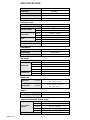
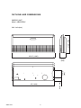
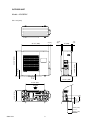
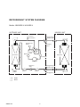
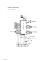
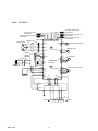
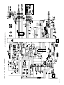
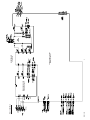
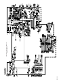
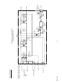
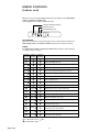
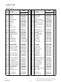
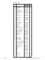
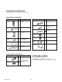
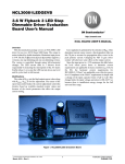
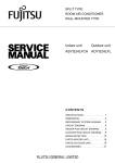
SPLIT TYPE
ROOM AIR CONDITIONER
CEILING
type (60Hz)
Models
Indoor unit
Outdoor unit
ABU36RSLX
AOU36RLX
C O N TEN TS
SPECIFICATIONS . . . . . . . . . . . . . . . . . . . . . . . 1
OUTLINE AND DIMENSIONS . . . . . . . . . . . . . 2
REFRIGERANT SYSTEM DIAGRAM . . . . . . . 4
CIRCUIT DIAGRAM . . . . . . . . . . . . . . . . . . . . . 5
INDOOR PCB CIRCUIT DIAGRAM . . . . . . . . 7
OUTDOOR PCB CIRCUIT DIAGRAM . . . . . . 8
ERROR DISPLAY . . . . . . . . . . . . . . . . . . . . . . 11
DISASSEMBLY ILLUSTRATION . . . . . . . . . . 13
PARTS LIST . . . . . . . . . . . . . . . . . . . . . . . . . . 21
STANDARD ACCESSORIES . . . . . . . . . . . . . 23
J06
S P E C I F I C AT I O N S
COOLING & HEATING
TYPE
INDOOR UNIT
ABU36RSLX
OUTDOOR UNIT
AOU36RLX
COOLING CAPACITY
34,100 / 33,500 BTU / h
HEATING CAPACITY
38,200 / 37,600 BTU / h
ELECTRICAL DATA
230 V / 208 V
POWER SOURCE
1
FREQUENCY
RUNNING CURRENT
INPUT WATTS
E.E.R.
60Hz
COOLING
18.3 A / 19.5 A
HEATING
15.6 A / 17.3 A
COOLING
4.22 kW / 4.08 kW
HEATING
3.60 kW / 3.60 kW
COOLING
2.37 / 2.40 kW/kW
HEATING
3.11 / 3.06 kW/kW
3.5 L/hr
MOISTURE REMOVAL
1,850 m3/hr
AIR CIRCULATION
COMPRESSOR
Hermetic type, 4 poles, Inverter, Twin rotary
TYPE
TNB220FPBM9
DISCRIMINATION
4 lb 14 oz (2,200g)
R410A
REFRIGERANT
FAN MOTOR
230 V
POWER SOURCE
MFA-45DZM
DISCRIMINATION
INDOOR UNIT
OUTDOOR UNIT
HIGH-SPEED
Cool 1,100 r.p.m. / Heat 1,100 r.p.m.
MED-SPEED
Cool 1,000 r.p.m. / Heat 900 r.p.m.
LOW-SPEED
Cool 850 r.p.m. / Heat 750 r.p.m.
MFE-45ROM
DISCRIMINATION
Cool 850 r.p.m. / Heat 900 r.p.m.
HIGH-SPEED
DIMENSIONS
INDOOR UNIT
HxWxD
OUTDOOR UNIT
HxWxD
9-1/2" x 65-1/2" x 27-5/8" inch
240 x 1,660 x 700 mm
32-3/4" x 35-1/2" x 13" inch
830 x 900 x 330 mm
WEIGHT
INDOOR UNIT
Net / Gross
48 kg / 61 kg
OUTDOOR UNIT
Net / Gross
64 kg / 70 kg
ADDITIONAL REFRIGERANT CHARGE (R410A)
Pipe Length
FULL CHARGE
AMOUNT
49 ft. (15 m)
4 lb 14 oz (2,200 g)
66 ft. (20 m)
5 lb 5 oz (2,400 g)
98 ft. (30 m)
6 lb 3 oz (2,800 g)
131 ft. (40 m)
7 lb 1 oz (3,200 g)
7 lb 15 oz (3,600 g)
164 ft. (50 m)
0.43 oz / ft. (40 g / m)
ADDITIONAL CHARGE
2006.01.23
1
OU T L I NE AND DI M ENSION S
INDOOR UNIT
Model : ABU36RSLX
27-5/8" (700)
Unit : inch (mm)
65-1/2" (1,660)
5-1/8" (130)
11-7/8"
(300)
9-1/2"
(240)
63" (1,600)
2005.12.27
2
OUTDOOR UNIT
Models : AOU36RLX
Unit : inch (mm)
3"(77)
13" (330)
1/2"
(12)
3/8"
(9)
7/8" (21)
17-3/8" (440)
32-3/4" (830)
35-1/2" (900)
1-1/4"
(31)
15-3/4" (400)
25-5/8" (650)
7-3/4" (196)
3-7/8"
(99)
14-5/8" (370)
Air Flow
5-3/4" (147)
6-3/4" (170)
2005.12.27
3
RE F RIG ERANT SYST EM D IA GR A M
Models : ABU36RSLX / AOU36RLX
INDOOR UNIT
OUTDOOR UNIT
Pressure
Check Valve
Refrigerant Pipe
15.88mm (5/8")
High Pressure
Switch
Condenser
Muffler
Charging
Valve
4-way
Valve
Evaporator
Accumulator
Compressor
Expansion
Valve
Strainer
Refrigerant Pipe
9.52mm (3/8")
Strainer
Charging Valve
: COOL
: HEAT
2006.01.23
4
CIRCUI T DI AG RAM
Model : ABU36RSLX
ROOM TEMPERATURE THERMISTOR
PIPE TEMPERATURE THERMISTOR
BLACK
BLACK
CN17 CN1
3 2 1 3 2 1
1
2
3
4
5
1
2
3
4
5
BROWN
RED
ORANGE
YELLOW
WHITE
BROWN
RED
ORANGE
YELLOW
WHITE
WHITE
BLACK
3
1
2
3
CN4
2 BLACK
1 WHITE
RED
1 WHITE
2 WHITE
CN10
FAN MOTOR F M
1 2
CN8
CN11
GRAY
GRAY
GRAY
CN13
1
1
PURPLE
2
2
3 BLUE
3
BROWN
RED
ORANGE
YELLOW
WHITE
BLUE
PURPLE
GRAY
1 2
CN7
CONTROLLER PCB
CN15
1
2
3
4
5
6
7
8
1
2
3
4
5
6
7
8
1 2
CN6
CN5
INDICATOR PCB
CN201
1
2
3
4
5
6
7
8
1
2
3
CN16
1 2
FAN MOTOR
CAPACITOR
1
2
3
4
5
M
STEP MOTOR
( UP / DOWN )
1
2
3
4
5
M
STEP MOTOR
( LEFT / RIGHT )
Use T 3.15A-250V
Fuse on F101
POWER SUPPLY PCB
3
2005.12.28
2
1
3
5
2
L
BLACK
WHITE
RED
RED
WHITE
BLACK
N
GREEN
1
G
TERMINAL
Model : AOU36RLX
PIPE TEMPERATURE
THERMISTOR
BLACK
DISCHARGE TEMPERATURE
THERMISTOR
CONNECTOR
RED
RED
1 2
1 2
WHITE
V
W304
BLACK
W
W303
BROWN
1
2 RED
3 ORANGE
WHITE
BROWN
CHOKE COIL
L1
L2
+
YELLOW
P
N
-
FUSE
F4 T 5A-250V
1
2
3 CN407
4
5
4
5
6 YELLOW
TERMINAL
BLUE
W12
W13
ORANGE
W16
BLACK
W17
W10
W11
CN1
CN34
1 2 3 4
1 2 3
WHITE
WHITE
BLACK
BROWN
RED
POSISTOR
1 2 3
TM102
BLACK
WHITE
YELLOW
BLUE
RED
BROWN
BLUE
ORANGE
YELLOW
WHITE
1
2
3
CN27 4
5
6
SOLENOID COIL
4WV
FAN MOTOR
RED
FUSE
F2 T 3.15A-250V
W21
W22
RED
HIGH PRESSURE SWITCH
1 BLACK
CN30 2
BLACK
3
1
2
CN802 3
4
CONTROLLER
5
6
PCB ASSY
EMI FILTER
2T
ORANGE
1 RED
CN37 2 RED
FM
EXPANSION VALVE COIL
EV
W200
BLACK
BLACK
ACTIVE
FILTER
MODULE
BLACK
1 2
EMI FILTER CN21 CN22 CN23 CN26 CN25
1T
U
V
BLACK
1 2
W305
W
HEAT SINK TEMPERATURE
THERMISTOR
BLACK
U
WHITE
COMPRESSOR TEMPERATURE
THERMISTOR
BROWN
BROWN
1 2
COMPRESSOR
OUTDOOR TEMPERATURE
THERMISTOR
BLUE
W9 W8
CN1
W3
W6
W7
W1
W2
WHITE
BLACK
WHITE
TM101
BLACK
BLACK
GREEN
POWER SUPPLY PCB ASSY
RED
EARTH G
2005.12.28
6
1 2(N) 3
L
N
G EARTH
2005.12.28
Model : ABU36RSLX
I N DO OR P C B C IR C UI T DI A GR AM
21
20
19
47
48
53
61
49
51
52
36
37
38
39
40
72
63
42
41
59
58
57
56
33
71
67
4
7
75
68
74
65
66
55
7
1
X1
70
P16
2
3
54
P15
P17
1
2
18
P21
P22
32
62
P01
R50 10K
<1/10W>
CR5
1000P
<R>
50
P36
11
R56
C39
0.1
<F>
15
X2
69
3
RESET
60
14
71
IC
P24
P23
73
P43
64
22
P44
XT1
23
P45
P03
25
24
P46
26
78
P47
P12
79
P13
5V
5V
UL1430 AWG22 BLUE
CN16-2
CN16-3
CN15-3
CN15-2
CN15-1
UL1430 AWG22 GRAY
UL1430 AWG22 PURPLE
CN16-1
CN9-5
CN9-4
CN9-3
80
P14
CN9-2
46
P32
45
P31
CN9-1
BZ1
PKM13EPY-4000
5V
R21 - R24
10K <1/10W> x 4
R57 1.0K
<1/10W> 14V
44
R25 - R28
1.0K <1/10W> x 4
I C6 (1/7)
uPA2003GR
C22 - C25
0.01 <F> x 4
6
5V
P30
43
GND 5
1 CS
6
P131
P67
NC 6
R77 - R79
10K <1/10W> x 3 I C7 BR93LC46RF
NC 7
2 SK
VCC
3 DI
9
10
P72
8
P71
4 DO
31
P55
8
30
P54
P70
29
P53
28
5
11
12
13
P52
P51
P130
P20
16
17
P26
P25
27
P27
34
35
77
76
P50
P56
P57
P11
P10
CONTROLLER PCB ASSEMBLY ( MAIN PCB )
K01AL-050RHSE-C1
2005.12.28
AC230V
60Hz
TERMINAL
HP-T3061-3
Model : AOU36RLX
POWER SUPPLY PCB
K04BA-0501HUE-P0
8
CONTROLLER PCB ASSY
K04AW-0504HUE-C1
INVERTER ASSY
EZ-005HHUE
2005.12.28
Model : AOU36RLX
CONTROLLER PCB ASSEMBLY ( MAIN PCB )
K04AW-0504HUE-C1
9
600/450V x 4
2005.12.28
AC VOLT OUT
*
W6
W5
or
W2
W4
or
WHITE
W9
BLACK
W8
GREEN
W3
WHITE
W7
BLACK
WHITE
EARTH
TO INDOOR UNIT
POWER SOURCE
230V
60Hz
BLACK
* W1
* AOU18RLX, AOU24RLX : W4 and W5
AOU36RLX, AOU42RLX : W1 and W2
Model : AOU36RLX
B
B
B
B
B
B
B
VA101
470V
<TNR>
VA102
470V
<TNR>
SA100
RA-302M
C101
3.3
<LE>
10
L1
RCH4730-021PF07
C104
0.033
<YE>
C105
0.033
<YE>
C106
3.3
<LE>
R60 1.0K
<1/10W>
(1%)
C60 +
220/16V
<PJ>
D60
5V DAN217U
CT1
CT-1B
C107
3.3
<LE>
L2
N200500K1D7C
TM100
POWER SUPPLY PCB ASSEMBLY
K04BA-0501HUE-P0
R61 3.74K
<1/10W>
(1%)
VR1
B2K
C112
0.015
<YE>
C113
0.015
<YE>
C64
0.1
<F>
C65
0.1
R68 22K <F>
<1/10W>
C111
3.3
<LE>
L4
RCH4730-021PF07
5V
3
2
1
CT OUT
WHITE
CN1
B3B-XASK-1-A
TM102
TM101
ERRO R CO NT EN TS
(Indoor unit)
Operation can be checked by lighting and flashing of the display section OPERATION,
TIMER, and VERTICAL SWING lamps.
Perform judgment in accordance with the following.
VERTICAL SWING lamp (Orange)
TIMER lamp (Green)
OPERATION lamp (Red)
MANUAL
AUTO
SWING
SWING
TIMER OERATION
TEST RUNNING
When the air conditioner is run by pressing the remote control unit test run button, the
OPERATION, TIMER, and VERTICAL SWING lamps flash slowly at the same time.
ERROR
The OPERATION, TIMER, and VERTICAL SWING lamps operate as follows (Table 1)
according to the error contents.
OPERATION TIMER lamp SWING lamp
(GREEN)
lamp (RED)
(ORANGE)
Error contents
Indoor EEPROM abnormal
Outdoor EEPROM abnormal
(2 times)
Indoor room temperature sensor open
(2 times)
Indoor room temperature sensor shortcircuited
(3 times)
Indoor heat exchanger temperature sensor open
(3 times)
Indoor heat exchanger temperature sensor shortcircuited
(4 times)
Float switch operated
(5 times)
Indoor signal abnormal
(5 times)
Outdoor signal abnormal
(6 times)
Indoor fan abnormal
(2 times)
Outdoor power source connection abnormal
(3 times)
Outdoor heat exchanger temperature sensor open
(3 times)
Outdoor heat exchanger temperature sensor shortcircuited
(4 times)
Outdoor temperature sensor open
(4 times)
Outdoor temperature sensor shortcircuited
(5 times)
Outdoor discharge pipe temperature sensor or compressor
temperature sensor open
(5 times)
Outdoor discharge pipe temperature sensor or compressor
temperature sensor shortcircuited
(6 times)
Outdoor high pressure abnormal
(7 times)
Outdoor discharge pipe temperature or compressor
temperature sensor abnormal
: 0.1s ON/0.1s OFF (flash)
: 0.5s ON/0.5s OFF (flash)
2005.12.28
: OFF
11
E R ROR CO NT ENT S
(outdoor unit)
1. Make a TEST RUN in accordance with the installation instruction sheet for the indoor unit.
2. When the product is operating:
1
Press the PUMP DOWN switch on the outdoor unit.
The LED on the outdoor unit circuit board lights, and
operation stops. At this point, recovery has not been
completed, so do not close the two- and three-way
valves.
2
The pump down operation (cooling operation) begins after three minutes. Close the three-way valve
(liquid) after operation starts.
3
After 2 - 3 minutes, operation stops. Close the threeway valve (gas) within one minute after operations
stops.
4
The LED will go out three minutes after it stops. Disconnect the power supply after confirming that the
LED has gone out.
2. OUTDOOR UNIT LEDS
When a malfunction occurs in the outdoor unit, the LED on
the circuit board lights to indicate the error. Refer to the following table for the description of each error according to the
LED.
LED
Error contents
1 flash
Communication error
(Indoor unit - Outdoor unit)
2 flash
Discharg pipe temperature sensor
3 flash
Outdoor heat exchanger temperature sensor
4 flash
Outdoor temperature sensor
7 flash
Compressor temperature sensor
8 flash
Heat sink temperature sensor
9 flash
Pressure switch abnormal
12 flash
IPM error
13 flash
Compressor rotor position cannot detect
14 flash
Compressor cannot operate
15 flash
Outdoor fan abnormal (upper fan)
16 flash
Outdoor fan abnormal (lower fan)
lighting
No error
*When the pump down operation is repeated, temporarily disconnect
the power supply after opening the closed valves (both liquid and gas).
Reconnect the power supply after 2 - 3 minutes and perform the pump
down operation.
*When the start of the operation after pump down operation has been
completed, temporarily disconnect the power supply after opening the
closed valves (both liquid and gas).
Reconnect the power supply after 2-3 minutes and be sure to perform
a test operation for cooling.
3-way valve
(Liquid)
SPECIAL INSTALLATION
SETTING
PUMP DOWN (Refrigerant collecting operation)
3-way valve
(Gas)
Perform the following procedures to collect the refrigerant
when moving the indoor unit or the outdoor unit.
1. When the product is stopped:
PUMP DOWN SW
1
Press the PUMP DOWN switch on the outdoor unit.
(The LED on the outdoor unit circuit board lights.)
2
The pump down operation (cooling operation) begins right away. After oparation starts, close the
three-way valve (liquid).
3
After 2 - 3 minutes, operation stops. Close the threeway valve (gas) within one minute after operations
stops.
4
The LED will go out three minutes after it stops.Disconnect the power supply after confirming that the
LED has gone out.
DANGER
This part (Choke coil) generates high voltages.
Never touch this part.
2006.01.25
12
2005.12.28
361
13
160
63
240-1
506
580
229
868
396
407
408
146
321
69
240
228
505
434
435
752
329
684
876-1
743
735
240-2
138
403
8
762
383
122 286
386
174
345-2
345-1
338-2
126
338-1
12
448
164
74
388
472
223
387
755
56
109
384
379
286
122
181
174
403
761
382
D IS AS SEM BL Y I L L USTR A TION
INDOOR UNIT
Model : ABU36RSLX
Model : ABU36RSLX
506
407
505
408
69
435
434
876-1
386
361
160
91
387
321
91
91
2005.12.28
14
Model : ABU36RSLX
321
63
387
436
385
424
438
868
684
763
876-2
227
2005.12.28
15
Model : ABU36RSLX
195
34
253-5
253-3
253-4
253-6
195
253-7
253-2
253-1
236
234
875
380
185-1
625
815-1
381-4
187
472
223
448
2005.12.28
16
Model : AOU36RLX
1
6
4
7
3
2
2005.12.28
5
17
Model : AOU36RLX
10
13
9
17
18
15
8
2006.01.17
18
14
Model : AOU36RLX
26
24
25
31
27
22
23
19
29
28
12
12
30
20
2005.12.28
19
Model : AOU36RLX
38
37
36
35
33 34
2005.12.28
20
P AR T S L I ST
INDOOR UNIT
Part No.
Ref.
No.
Description
ABU36RSLX
Ord.
Q'ty
Ref.
No.
Part No.
Description
ABU36RSLX
8
12
34
56
63
69
74
91
109
122
Air Filter
Base Assy
Capacitor
Sirocco Fan Assy
Panel (Front)
Louver
Intake Grille
Hinge
Casing
Bearing-B Assy
9359739005
9359680000
9900270216
9359701002
9359734000
9359719007
9359738008
9359699002
9359704003
9357921006
345-1
345-2
361
379
380
381-4
382
383
384
385
Filter Guide-R
Filter Guide-L
Bushing
Hinge Plate (Grille)
Locking Spacer KGLS-6S
Spacer
Cover (Decoration)-R
Cover (Decoration)-L
Shaft
Indicator PCB Assy
9359692003
9359693000
9359733003
9359694007
313209391403
0600118075
9359744009
9359745006
9359707004
9705891029
126
138
146
160
164
174
181
185-1
187
195
Bracket (Motor)
Separate Wall
Evaporator Assy
Drain Pan Sub Assy
Fan Motor Assy-IN
Hanger
Hole Cover
Rubber Bushing
Clamp No.1219
Clamp SKB-100
9359681007
9359700005
9371073040
9360429018
9360457004
9359742005
9359691006
9357376004
313361271706
313361275805
386
387
388
396
403
407
408
424
434
435
Panel Left Assy
Kit (Panel Right Assy)
Joint Assy
Rfm Bracket Metal
Fixture (Bearing)
Rod (Motor)
Link (Louver)
Sector Gear
Base (Louver)
Louver Spring
9359685005
9371361017
9359706007
9359697008
9359687009
9359723004
9359726005
9359729006
9359718000
9359720003
223
227
228
229
234
236
Control Box Assy
Badge "FUJITSU"
Insulation (Louver)-R
Insulation (Louver)-L
Thermistor (Room)
Controller PCB Assy
436
438
448
472
505
506
580
625
684
735
Flap Spring
Pinion Gear
Control Box-B
Control Box-A
Stopper (Louver)
Rod (Louver)
Cover (Top)
Cord Bushing
Motor Base
Distributor Assy
9359730002
9359728009
9359713005
9359712008
9359724001
9359725008
9359737001
9359240006
9359727002
9360455000
9702321017
9702322014
9702311018
9702323011
9702319014
9702317010
9702318017
9359686002
9359731009
9373038214
743
752
755
761
762
763
815-1
868
875
876-1
Remote Control Holder Case
Bracket Panel (Pipe)
Cover (Casing)
Kit (Cover Side-R)
Kit (Cover Side-L)
Cover (Receiver)
Terminal-7P
PCB Holder
Power Supply PCB Assy
Motor, Step-H
9305642014
9359688006
9359705000
9371364018
9371365015
9359714002
9703403019
9359736004
9704561350
9360479013
9359702009
9359703006
876-2 Motor, Step
--Thermistor (Pipe)
240
Remote Control Unit
240-1 Cover Panel (Pipe)-L
240-2 Cover Panel (Pipe)-R
253-1
253-2
253-3
253-4
253-5
253-6
253-7
286
321
329
Wire Assy (Terminal)
Wire Assy (Terminal)
Wire Assembly
Wire Assy (Connector)
Wire Assy (Connector)
Wire Assy (Connector)
Wire Assy (Connector)
Bracket (Bearing)
Flap Assy
Coupling Pipe Assy
338-1 Fixture (Motor)
338-2 Fixture (Motor)-B
2006.06.08
9362025003
9359735014
9359721000
9359722007
9703299025
9705914285
(K01AL-050RHSE-C1)
9371190051
9359690009
9359689003
21
Ord.
Q'ty
9900362010
9900022020
When you order parts, please make a photocopy of this page
and fill the number of the parts in the "Order" column.
OUTDOOR UNIT
Ref.
No.
1
2
3
4
5
6
7
8
2006.06.08
Part No.
Description
AOU36RLX
Top Panel Sub Assy
Front Panel
Fan Guard
Grip Side
Service Panel Sub Assy
Right Panel Sub Assy
Emblem Rear
Propeller Fan Assy
9374417025
9374094066
9374330010
9374173013
9374415038
9374416073
9351355005
9366378020
9
10
Fan Motor
Condenser-A Assy
9602114016
9374433148
12
13
14
15
17
Strainer Assy
Separate Wall Assy
Cap Foot
Base Assy
3-Way Valve Assy
9372524015
9375226015
9374345014
9374166183
9372205044
18
19
20
22
23
24
25
26
3-Way Valve Assy
Check Joint Assy
Compressor Assy
4-Way Valve
Solenoid
Pressure Switch
Inlet Pipe Cond A Assy
Inlet Pipe Cond B Assy
9372205075
9372802038
9373711018
9900164010
9900165055
9900186012
9373461067
9373463054
27
28
29
30
31
33
34
35
Outlet Pipe Cond A Assy
Expansion Valve Assy
Coil (Expansion Valve)
Distributor
Discharge Pipe A Assy
Terminal 2P
Terminal 5P
ACTPM
9374266050
9370947113
9900057039
9369128004
9372264140
9701971015
9900203023
9703457012
36
37
38
----
Holder Thermo
Inverter PCB Assy
Power PCB Assy
Fuse 3.15A-250V
9372797013
9705642102
9705647053
0600239534
----------
Thermistor (Outdoor Temp.)
Heat Exchanger Thermistor
Thermistor (Discharge)
9900378035
9900374013
9704219114
-------------------------
Compressor Thermistor
Thermistor
Heatsink Thermistor
Transformer
Varistor
Arrester
Relay
Relay
9900156022
9704265012
9900311018
9702334024
0000361224
0600280147
9900117016
9900007010
----------
Switch Push
Switch Slide
Drain Pipe Assy
9703476013
9701392018
9301102000
----
Drain Cap
313166024302
22
Ord.
Q'ty
When you order parts, please make a photocopy of this page
and fill the number of the parts in the "Order" column.
STANDARD ACCESSORIES
The following installation parts are furnished. Use them as required.
INDOOR UNIT ACCESSORIES
Name and Shape
Q'ty
Remote
control unit
Application
Name and Shape
Use for air conditioner
operation
Q'ty
Coupler heat insulator (large)
2
Application
For indoor side pipe joint
(Gas pipe)
1
Coupler heat insulator (small)
Battery (penlight)
1
For remote control unit
2
Nylon fastener
Remote control
unit holder
For mounting the remote
control unit
1
Tapping screw
(ø3 x 12)
2
Drain hose insulation
For remote control unit
holder installation
Adhesive type 70 x 230
For indoor side pipe joint
(Liquid pipe)
Large For fixing the coupler heat
4
insulator
Small
4
Special nut A
(large flange)
4
For installing indoor unit
Special nut B
(small flange)
4
Installation
template
1
For installing indoor unit
For positioning the indoor
unit
1
For connecting the piping
Auxiliary pipe assembly
VT wire
1
For fixing the drain hose
L 280 mm
1
OUTDOOR UNIT ACCESSORIES
Name and Shape
Q'ty
OPTIONAL PARTS
Application
Drain pipe
1
Drain cap
The following options are available.
DRAIN PUMP UNIT : UTR-DPB241 (P/N 9034087001)
WIRED REMOTE CONTROLLER UNIT : UTB-UUB(P/N 9075887004)
For outdoor unit drain
piping work (May not be
supplied, depending on
the model.)
5
2005.12.28
23
0512G2981