1
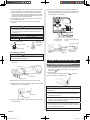
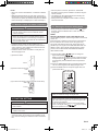
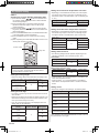
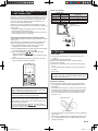
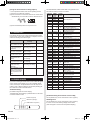
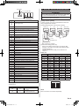
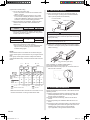
AIR CONDITIONER
INDOOR UNIT
Ceiling type
INSTALLATION MANUAL
For authorized service personnel only.
Contents
1.
SAFETY PRECAUTIONS��������������������������������������������� 2
7.
2.
ABOUT THE UNIT�������������������������������������������������������� 2
2.1. Precautions for using R410A refrigerant
2.2. Special tools for R410A
2.3. Accessories
2.4. Optional parts
REMOTE CONTROLLER SETTING�������������������������� 11
7.1. Load batteries (R03/LR03 × 2)
7.2. Remote control unit holder installation
8.
FUNCTION SETTING������������������������������������������������ 11
8.1. Entering the function setting mode
8.2. Function setting
9.
SELECTING THE REMOTE CONTROL UNIT
SIGNAL CODE����������������������������������������������������������� 13
3.
4.
INSTALLATION WORK������������������������������������������������ 3
3.1. Selecting an installation location
3.2. Installation dimension
3.3. Installation the unit
PIPE INSTALLATION��������������������������������������������������� 6
4.1. Selecting the pipe material
4.2. Pipe requirement
4.3. Flare connection (pipe connection)
4.4. Installing heat insulation
5.
INSTALLING DRAIN PIPES����������������������������������������� 8
6.
ELECTRICAL WIRING������������������������������������������������� 9
6.1. Electrical requirement
6.2. Wiring method
10. TEST RUN������������������������������������������������������������������ 14
11. CHECK LIST��������������������������������������������������������������� 14
12. ERROR CODES��������������������������������������������������������� 15
13. SPECIAL INSTALLATION METHODS����������������������� 16
14. FRESH-AIR INTAKE�������������������������������������������������� 16
15. CUSTOMER GUIDANCE������������������������������������������� 16
PART NO. 9379122009-02
1125-9379122009.indd
1
2008/11/26
7:57:04
1. SAFETY PRECAUTIONS
• Be sure to read this Manual thoroughly before installation.
• The warnings and precautions indicated in this Manual
contain important information pertaining to your safety. Be
sure to observe them.
• Hand this Manual, together with the Operating Manual, to
the customer. Request the customer to keep them on hand
for future use, such as for relocating or repairing the unit.
WARNING
This mark indicates procedures which,
if improperly performed, might lead to
the death or serious injury of the user.
• Request your dealer or a professional installer to install the indoor unit in accordance with this Installation
Manual. An improperly installed unit can cause serious
accidents such as water leakage, electric shock, or fire. If
the indoor unit is installed in disregard of the instructions
in the Installation Manual, it will void the manufacturer’s
warranty.
2.2. Special tools for R410A
WARNING
• To install a unit that uses R410A refrigerant, use dedicated tools and piping materials that have been manufactured specifically for R410A use. Because the pressure
of R410A refrigerant is approximately 1.6 times higher
than the R22, failure to use dedicated piping material or
improper installation can cause rupture or injury.
Furthermore, it can cause serious accidents such as
water leakage, electric shock, or fire.
Tool name
Changes
Gauge manifold
The pressure in the refrigerant
system is extremely high and cannot be measured with a conventional gauge. To prevent erroneous
mixing of other refrigerants, the
diameter of each port has been
changed. It is recommended to use
a gauge manifold with a high
pressure display range of –0.1 to
5.3 MPa and a low pressure display range of –0.1 to 3.8 MPa.
Charging hose
To increase pressure resistance,
the hose material and base size
were changed.
(The charging port thread diameter
for R410A is 1/2 UNF 20 threads
per inch.)
Vacuum pump
A conventional vacuum pump can
be used by installing a vacuum
pump adapter.
Be sure that the pump oil does
not backflow into the system. Use
one capable for vacuum suction of
–100.7 kPa (5 torr, –755 mmHg).
• Do not turn ON the power until all work has been completed. Turning ON the power before the work is completed can cause serious accidents such as electric shock
or fire.
• If refrigerant leaks while work is being carried out, ventilate the area. If the refrigerant comes in contact with a
flame, it produces a toxic gas.
• Installation work must be performed in accordance with
national wiring standards by authorized personnel only.
CAUTION
This mark indicates procedures which,
if improperly performed, might possibly
result in personal harm to the user, or
damage to property.
2. ABOUT THE UNIT
Gas leakage detector
Special gas leakage detector for
R410A refrigerant.
2.1. Precautions for using R410A
refrigerant
WARNING
• Do not introduce any substance other than the prescribed
refrigerant into the refrigeration cycle. If air enters the
refrigeration cycle, the pressure in the refrigeration cycle
will become abnormally high and cause the piping to
rupture.
• If there is a refrigerant leak, make sure that it does
not exceed the concentration limit. If a refrigerant leak
exceeds the concentration limit, it can lead to accidents
such as oxygen starvation.
• Do not touch refrigerant that has leaked from the refrigerant pipe connections or other area. Touching the refrigerant directly can cause frostbite.
• If a refrigerant leak occurs during operation, immediately
vacate the premises and thoroughly ventilate the area. If
the refrigerant comes in contact with a flame, it produces
a toxic gas.
En-2
1125-9379122009.indd
2
2008/11/26
7:57:04
2.3. Accessories
2.4. Optional parts
Exterior
WARNING
• For installation purposes, be sure to use the parts supplied by the manufacturer or other prescribed parts.
The use of non-prescribed parts can cause serious accidents such as the unit falling, water leakage, electric
shock, or fire.
• The following installation parts are furnished. Use them as
required.
• Keep the Installation Manual in a safe place and do not
discard any other accessories until the installation work has
been completed.
Name and Shape
Q’ty
Drain hose insulation
Coupler heat insulation
(Large)
Coupler heat insulation
(Small)
UTB-*UD
Round
duct
Drain
pump
unit
UTD-RF204
Unit control is performed by wired
remote controller
For Ceiling type
UTR-DPB241 For Ceiling type
3. INSTALLATION WORK
1
For fixing the drain hose
L : 280 mm
2
For indoor side pipe joint
(Gas pipe)
1
For indoor side pipe joint
(Liquid pipe)
4
For fixing the coupler heat
insulator
Binder
(Small)
4
For fixing the coupler heat
insulator
Special nut A
(Large flange)
4
Special nut B
(Small flange)
4
Installation
template
1
For installing indoor unit
For installing indoor unit
For positioning the indoor
unit
For connecting the piping
1
Remote control
unit
Use for air conditioner
operation
1
Battery (Penlight)
For remote control unit
Remote control
unit holder
Use as remote control unit
holder
1
2
Especially, the installation place is very important for the split
type air conditioner because it is very difficult to move from
place to place after the first installation.
3.1. Selecting an installation location
Decide the mounting position together with the customer as
follows.
WARNING
• Select installation locations that can properly support the
weight of the indoor unit. Install the units securely so that
they do not topple or fall.
CAUTION
• Do not install the indoor unit in the following areas:
• Area with high salt content, such as at the seaside. It
will deteriorate metal parts, causing the parts to fall or
the unit to leak water.
• Area filled with mineral oil or containing a large amount
of splashed oil or steam, such as a kitchen. It will deteriorate plastic parts, causing the parts to fall or the unit
to leak water.
• Area that generates substances that adversely affect
the equipment, such as sulfuric gas, chlorine gas, acid,
or alkali. It will cause the copper pipes and brazed joints
to corrode, which can cause refrigerant leakage.
• Area that can cause combustible gas to leak, contains
suspended carbon fibers or flammable dust, or volatile
inflammables such as paint thinner or gasoline. If gas
leaks and settles around the unit, it can cause a fire.
• Area where animals may urinate on the unit or ammonia may be generated.
• Do not install where there is the danger of combustible
gas leakage.
2
Screw
(M3 × 12)
Wired
remote
controller
Summary
Description
Binder
(Large)
Auxiliary pipe
assembly
Model No.
Adhesive type 70 × 230
1
VT wire
Parts name
For remote control unit
holder installation
• Do not install the unit near a source of heat, steam, or
flammable gas.
• Install the indoor unit, outdoor unit, power supply cable,
transmission cable, and remote control cable at least 1 m
away from a television or radio receivers. The purpose of
this is to prevent TV reception interference or radio noise.
(Even if they are installed more than 1 m apart, you could
still receive noise under some signal conditions.)
• If children under 10 years old may approach the unit, take
preventive measures so that they cannot reach the unit.
En-3
1125-9379122009.indd
3
2008/11/26
7:57:04
(1) Install the indoor unit on a place having a sufficient
strength so that it withstands against the weight of the
indoor unit.
(2) The inlet and outlet ports should not be obstructed; the air
should be able to blow all over the room.
(3) Leave the space required to service the air conditioner.
(4) Install the unit where connection to the outdoor unit is
easy.
(5) Install the unit where the connection pipe can be easily
installed.
(6) Install the unit where the drain pipe can be easily installed.
(7) Install the unit where noise and vibrations are not amplified.
(8) Take servicing, etc., into consideration and leave the spaces. Also install the unit where the filter can be removed.
(9) Do not install the unit where it will be exposed to direct
sunlight.
3.2. Installation dimension
• The ceiling rear height as shown in the figure.
Ceiling
3.3. Installation the unit
WARNING
• Install the air conditioner in a location which can withstand a load of at least five times the weight of the main
unit and which will not amplify sound or vibration. If the
installation location is not strong enough, the indoor unit
may fall and cause injuries.
3.3.1. Preparing indoor unit installation
Remove the intake grille and side cover
(1) Remove the two Air filters.
(2) Remove the two Intake grilles.
4 Left rear drain and ○
5 Left drain: Remove air filters
For ○
and intake grilles at three places.
(3) Remove the Side cover A (Right side) and Side cover B
(Right and Left side).
5 Left drain: Remove both the Side cover A (Right
For ○
and Left side).
(4) This air conditioner can be set up to intake fresh air.
For information about how to install for fresh-air intake,
refer to “14. FRESH-AIR INTAKE”.
Air filter
INDOOR UNIT
Intake grille
Tapping screw
80 or over
150 or over
1000 or over
2500 or over
Ceiling
INDOOR UNIT
Side cover B
(Left side)
10 or over
Side cover A (Right side)
Side cover B (Right side)
Obstruction
Unit : mm
Floor
[FOR HALF CONCEALED INSTALLATION]
Ceiling panel
3.3.2. Indoor unit installation
• You can use the accessory template to help you install the
indoor unit.
• The template helps you determine the appropriate locations
for suspension bolts and pipe opening (drain pipe and connection cable).
Drilling position for Suspension bolt
INDOOR UNIT
Ceiling
80 or over
Wall
Ceiling panel
150 or over
1000 or over
2500 or over
Template
3.3.3. Location of ceiling suspension bolts
10 or over
Obstruction
Floor
Drilling position for piping
30
Suspension bolt pitch 1600
30
Dimensions
(Space Required
for Installation)
10
155
Unit : mm
INDOOR UNIT (TOP VIEW)
INDOOR UNIT
300
Suspension bolt should
extendoutward30to75mm.
Unit : mm
En-4
1125-9379122009.indd
4
2008/11/26
7:57:04
[For Half-Concealed Installation]
• Suspension-bolt pitch should be as shown in the figure.
40
Ceiling Opening: 1580
40
Ceiling panel
Ceiling Opening: 640
3.3.6. Installing the indoor unit
(1) Lift unit so that suspension bolts pass through the suspension fittings at the sides (four places), and slide the unit
back.
Ceiling
15
Ceiling panel
Wall
Suspension bolt should
extendoutward30to50mm.
INDOOR UNIT
Unit : mm
Ceiling panel
3.3.4. Select piping direction
• Select connection piping and drain piping directions.
5 Left piping
(Drain pipe only)
4 Left rear piping 2 Top piping
(Drain pipe only) (Connection pipe only)
1 Right rear piping
INDOOR UNIT (TOP VIEW)
3 Right
piping
Cut off the piping outlet cutting groove
with a hacksaw, etc.
5 Left piping]
4 Left rear piping, ○
[FOR ○
• Transfer the Drain cap and Drain cap seal.
Drain Cap seal
Wall
INDOOR UNIT
(2) Fasten the indoor unit into place by tightening-up the
special “B” bolts and the M10 nuts. Make sure that unit is
secure and will not shift back and forth.
[For Half-Concealed Installation]
When installing the indoor unit in a semi-concealed orientation, make sure to reinforce the insulation of the unit on all
sides. Drops of water may fall from the unit if it is not thoroughly insulated.
Glass wool insulate
(10 to 20 mm thick)
Drain Cap
Indoor Unit
Drain Pan
Drain Cap Seal
Drain Cap
INDOOR UNIT
(TOP VIEW)
Wall
Push cap all the way on
(as far as it will go).
3.3.5. Drilling the holes and attaching the suspension bolts
(1) Drill ø25 mm holes at the suspension-bolt locations.
(2) Install the bolts, then temporarily attach Special nuts A and
B and a normal M10 nut to each bolt. (The two special
nuts are provided with the unit. The M10 nut must be
obtained locally.) Refer to the figure.
Bolt Strength [N (kgf)]
Ceiling panel
Ceiling panel
CAUTION
• In order to check the drainage, be sure to use a level during installation of the indoor unit. If the installation site of
the indoor unit is not level, water leakage may occur.
980 to 1470 (100 to 150)
Special nut A (Included)
10 to 15
Special nut B (Included)
M10 Nut (Obtained locally)
Unit : mm
En-5
1125-9379122009.indd
5
2008/11/26
7:57:05
• Use pipe with water-resistant heat insulation.
4. PIPE INSTALLATION
CAUTION
CAUTION
• Be more careful that foreign matter (oil, water, etc.) does
not enter the piping than with refrigerant R410A models.
Also, when storing the piping, securely seal the openings
by pinching, taping, etc.
• While welding the pipes, be sure to blow dry nitrogen gas
through them.
4.1. Selecting the pipe material
CAUTION
• Do not use existing pipes.
• Use pipes that have clean external and internal sides
without any contamination which may cause trouble during use, such as sulfur, oxide, dust, cutting waste, oil, or
water.
• It is necessary to use seamless copper pipes.
Material : Phosphor deoxidized seamless copper pipes
It is desirable that the amount of residual oil is less than
40 mg/10 m.
• Do not use copper pipes that have a collapsed, deformed, or discolored portion (especially on the interior
surface). Otherwise, the expansion valve or capillary tube
may become blocked with contaminants.
• Improper pipe selection will degrade performance. As an
air conditioner using R410A incurs pressure higher than
when using conventional refrigerant, it is necessary to
choose adequate materials.
• Thicknesses of copper pipes used with R410A are as shown
in the table.
• Never use copper pipes thinner than those indicated in the
table even if they are available on the market.
Thicknesses of Annealed Copper Pipes (R410A)
Pipe outside diameter [mm (in.)]
6.35 (1/4)
9.52 (3/8)
12.70 (1/2)
15.88 (5/8)
19.05 (3/4)
Thickness [mm]
0.80
0.80
0.80
1.00
1.20
4.2. Pipe requirement
CAUTION
• Refer to the Installation Manual of the outdoor unit for
description of the length of connecting pipe or for difference of its elevation.
Diameter [mm (in.)]
Liquid
Gas
9.52 (3/8)
15.88 (5/8)
• Install heat insulation around both the gas and liquid
pipes. Failure to do so may cause water leaks.
Use heat insulation with heat resistance above 120 °C.
(Reverse cycle model only)
In addition, if the humidity level at the installation location of the refrigerant piping is expected to exceed 70 %,
install heat insulation around the refrigerant piping.
If the expected humidity level is 70-80 %, use heat
insulation that is 15 mm or thicker and if the expected
humidity exceeds 80 %, use heat insulation that is 20 mm
or thicker. If heat insulation is used that is not as thick as
specified, condensation may form on the surface of the
insulation.
In addition, use heat insulation with heat conductivity of
0.045 W/(m·K) or less (at 20 °C).
4.3. Flare connection (pipe connection)
4.3.1. Flaring
• Use special pipe cutter and flare tool exclusive for R410A.
(1) Cut the connection pipe to the necessary length with a
pipe cutter.
(2) Hold the pipe downward so that cuttings will not enter the
pipe and remove any burrs.
(3) Insert the flare nut (always use the flare nut attached to
the indoor and outdoor units respectively) onto the pipe
and perform the flare processing with a flare tool. Use the
special R410A flare tool, or the conventional flare tool.
Leakage of refrigerant may result if other flare nuts are
used.
(4) Protect the pipes by pinching them or with tape to prevent
dust, dirt, or water from entering the pipes.
Check if [L] is flared uniformly
and is not cracked or scratched.
B
Die
A
L
Pipe
Pipe outside
diameter
[mm (in.)]
6.35 (1/4)
9.52 (3/8)
12.70 (1/2)
15.88 (5/8)
19.05 (3/4)
Dimension A [mm]
Flare tool for R410A,
clutch type
0
Dimension B-0.4
[mm]
0 to 0.5
9.1
13.2
16.6
19.7
24.0
When using conventional flare tools to flare R410A pipes,
the dimension A should be approximately 0.5 mm more than
indicated in the table (for flaring with R410A flare tools) to
achieve the specified flaring. Use a thickness gauge to measure the dimension A.
Width across
Pipe outside
diameter [mm (in.)]
6.35 (1/4)
9.52 (3/8)
12.70 (1/2)
15.88 (5/8)
19.05 (3/4)
Width across flats
of Flare nut [mm]
17
22
26
29
36
En-6
1125-9379122009.indd
6
2008/11/26
7:57:05
4.3.2 Bending pipes
• If pipes are shaped by hand, be careful not to collapse
them.
• Do not bend the pipes in an angle more than 90°.
• When pipes are repeatedly bend or stretched, the material
will harden, making it difficult to bend or stretch them any
more. Do not bend or stretch the pipes more than three
times.
CAUTION
• To prevent breaking of the pipe, avoid sharp bends.
• If the pipe is bent repeatedly at the same place, it will
break.
4.3.3. Pipe connection
CAUTION
• Be sure to apply the pipe against the port on the indoor
unit and the outdoor unit correctly. If the centering is improper, the flare nut cannot be tightened smoothly. If the
flare nut is forced to turn, the threads will be damaged.
• Do not remove the flare nut from the indoor unit pipe until
immediately before connecting the connection pipe.
• Do not use mineral oil on flared part. Prevent mineral
oil from getting into the system as this would reduce the
lifetime of the units.
(1) Remove the filter guide.
Indoor unit
Filter guide
(4) When the flare nut is tightened properly by your hand,
hold the body side coupling with a separate spanner, then
tighten with a torque wrench. (See the table below for the
flare nut tightening torques.)
CAUTION
• Hold the torque wrench at its grip, keeping it in the right
angle with the pipe, in order to tighten the flare nut correctly.
• Tighten the flare nuts with a torque wrench using the
specified tightening method. Otherwise, the flare nuts
could break after a prolonged period, causing refrigerant
to leak and generate a hazardous gas if the refrigerant
comes into contact with a flame.
Tighten with two wrenches.
Holding wrench
Torque wrench
Indoor unit pipe
(Body side)
Flare nut [mm (in.)]
6.35 (1/4) dia.
9.52 (3/8) dia.
12.70 (1/2) dia.
15.88 (5/8) dia.
19.05 (3/4) dia.
Flare nut
Connection pipe
Tightening torque [N·m (kgf·cm)]
16 to 18 (160 to 180)
32 to 42 (320 to 420)
49 to 61 (490 to 610)
63 to 75 (630 to 750)
90 to 110 (900 to 1,100)
(2) Detach the caps and plugs from the pipes.
(3) Center the pipe against the port on the indoor unit, and
then turn the flare nut by hand.
Connection pipe (Gas)
Connection pipe (Liquid)
Indoor unit
• For 2 Top piping and 3 Right piping connections, use the
Auxiliary pipe (Gas pipe) provided.
2 Top piping
Connection pipe (Gas)
Indoor unit (rear)
Connection pipe (Gas)
Auxiliarypipe(Gaspipe)
3 Right piping
En-7
1125-9379122009.indd
7
2008/11/26
7:57:05
• Always heat insulate (8 mm or over thick) the indoor side of
the drain pipe.
4.4. Installing heat insulation
Drain pipe
CAUTION
• After checking for gas leaks (refer to the Installation
Manual of the outdoor unit), perform this section.
• Install heat insulation around both the large (gas) and
small (liquid) pipes. Failure to do so may cause water
leaks.
After checking for gas leaks, insulate by wrapping insulation around the two parts (Gas and Liquid) of the indoor unit
coupling, using the coupler heat insulation.
After installing the coupler heat insulation, wrap both ends
with vinyl tape so that there is no gap.
Secure both ends of the heat insulation material using Binder.
And finally fix connection pipe (Liquid) to connection pipe
(Gas) by rolling vinyl tape over coupler heat insulation (Gas)
and coupler heat insulation (Liquid).
Coupler heat insulation (Large)
Good
Arrange the drain pipe
lower than this portion.
Lifted up
Bad
Wave
Bad
End in water
Supporter
1.5 to 2
Unit : m
(1) Install insulation for the drain pipe.
Cut the included insulation material to an appropriate size
and adhere it to the pipe.
Connection pipe (Gas)
Indoor unit
Connection pipe (Liquid)
Drain pipe
Coupler heat insulation (Small)
Binder (Large)
No gap
Indoor unit (drain port)
Insulation for drain pipe
(To be obtained locally. Length
should be at least 8 mm.)
Drain pipe insulation (accessories)
Indoor unit
Drain pipe insulation
Coupler heat
insulation
Indoor unit
Binder (Small)
Connection pipe (Gas)
Indoor unit
Drain pipe
No gap
10 or over
Unit : mm
(2) If “ ○
1 Right rear piping” : fasten the drain pipe with VT wire
so that the pipe slopes correctly within the indoor unit.
Connection pipe (Liquid)
VT wire
Vinyl tape
Drain hose
• When using an auxiliary pipe, make sure that the Binder
used is insulated in the same way
CAUTION
• There should be no gaps between the insulation and the
unit.
5. INSTALLING DRAIN PIPES
CAUTION
• Install the drain pipe in accordance with the instructions in this Installation Manual and keep the area warm
enough to prevent condensation. Problems with the piping may lead to water leaks.
• Install the drain pipe with downward gradient (1/50 to 1/100)
and so there are no rises or traps in the pipe.
• Use general hard polyvinyl chloride pipe (VP25) [outside
diameter 38 mm].
• During installation of the drain pipe, be careful to avoid
applying pressure to the drain port of the indoor unit.
• When the pipe is long, install supporters.
• Do not perform air bleeding.
Indoor unit (rear view)
(3) If the drain hose will not be connected to the right rear
piping, cut the hole cover at the points indicated in Fig. (a),
and attach it to the piping hole as shown in Fig. (b).
(a)
Hole cover
Cutx5
(b)
En-8
1125-9379122009.indd
8
2008/11/26
7:57:05
6. ELECTRICAL WIRING
6.1. Electrical requirement
Connection cable (mm2)
WARNING
• Electrical work must be performed in accordance with
this Manual by a person certified under the national or
regional regulations. Be sure to use a dedicated circuit
for the unit.
An insufficient power supply circuit or improperly performed electrical work can cause serious accidents such
as electric shock or fire.
• Before starting work, check that power is not being supplied to the indoor unit and outdoor unit.
• Use the included connection cables and power cables or
ones specified by the manufacturer. Improper connections, insufficient insulation, or exceeding the allowable
current can cause electric shock or fire.
• For wiring, use the prescribed type of wires, connect
them securely, making sure that there are no external
forces of the wires applied to the terminal connections.
Improperly connected or secured wires can cause serious accidents such as overheating the terminals, electric
shock, or fire.
MAX.
MIN.
2.5
1.5
• Use conformed cable with Type 245 IEC57.
• Perform all electrical work according to the standard.
• Install circuit breakers, which have the terminal spacing
of more than 3 mm, in a place of near the indoor unit and
outdoor unit.
CAUTION
• Be sure to execute the electrical work according to the
Laws of each country and the Installation Instructions.
In addition, be sure to set as exclusive line and use the
rated voltage and circuit breaker.
6.2. Wiring method
6.2.1. Connection diagrams
• Connection cable (to outdoor unit)
• Do not modify the power cables, use extension cables,
or use any branches in the wiring. Improper connections,
insufficient insulation, or exceeding the allowable current
can cause electric shock or fire.
• Match the terminal block numbers and connection cable
colors with those of the outdoor unit. Erroneous wiring
may cause burning of the electric parts.
• Wired remote controller cable
3
2
1
* Ground the remote controller if it has a ground wire.
6.2.2. Connection cable preparation
Keep the earth wire longer than the other wires.
30
• Install sleeves into any holes made in the walls for wiring.
Otherwise, a short circuit could result.
• Install a ground leakage breaker.
If a ground leakage breaker is not installed, it may cause
electric shock or fire.
• Always connect the ground wire.
Improper grounding work can cause electric shocks.
• Install the remote controller wires so as not to be direct
touched with your hand.
*
Black
White
Red
Indoor unit
side
• Always fasten the outside covering of the connection
cable with the cable clamp. (If the insulator is chafed,
electric leakage may occur.)
• Install a ground leakage breaker. In addition, install the
ground leakage breaker so that the entire AC main power
supply is cut off at the same time. Otherwise, electric
shock or fire could result.
Power line
Indoor unit
side
• Securely connect the connection cables to the terminal
blocks. In addition, secure the cables with wiring holders.
Improper connections, either in the wiring or at the ends
of the wiring, can cause a malfunction, electric shock, or
fire.
• Securely install the electrical box cover on the unit.
An improperly installed electrical box cover can cause
serious accidents such as electric shock or fire through
exposure to dust or water.
Control line
3
2
1
mm
Earth wire
40
•Usea4-corewirecable.
mm
or
re Power supply cable
or connection cable
mo
How to connect wiring to the terminals.
(For strand wiring)
(1) Use crimp-type terminals with insulating sleeves as shown
in the figure below to connect to the terminal block.
(2) Securely crimp the crimp-type terminals to the wires using
an appropriate tool so that the wires do not come loose.
Str
i
0
p1
mm
Crimp-type
terminal
Sleeve
En-9
1125-9379122009.indd
9
2008/11/26
7:57:05
(3) Use the specified wires, connect them securely, and fasten
them so that there is no stress placed on the terminals.
(4) Use an appropriate screwdriver to tighten the terminal
screws. Do not use a screwdriver that is too small, otherwise, the screw heads may be damaged and prevent the
screws from being properly tightened.
(5) Do not tighten the terminal screws too much, otherwise,
the screws may break.
(6) See the table below for the terminal screw tightening
torques.
(5) Attach the connection cable and cable clips. Make sure
that they are positioned so that they will not interfere with
opening and closing of the intake grille or with removal
and installation of the air filters.
1 2 3
Power
Remote
1 2 3
WARNING
• Use crimp-type terminals and tighten the terminal screws
to the specified torques, otherwise, abnormal overheating
may be produced and possibly cause serious damage
inside the unit.
M4 screw
M5 screw
Tightening torque [N·m (kgf·cm)]
1.2 to 1.8 (12 to 18)
2.0 to 3.0 (20 to 30)
Screw with
special washer
Wire
Screw with
special washer
Crimp-type terminal
Connection cable
(To outdoor unit)
Wired remote controller cable
(Option)
Connection cable
Crimp-type
terminal
Wire
Terminal blocks
6.2.3. Wiring procedure
Cable clip
Wired remote
controller cable
CAUTION
• Use care not to mistake the power supply cable and connection wires when installing.
(1) Remove the two tapping screws and pull the Control box
downward.
7. REMOTE CONTROLLER SETTING
7.1. Load batteries (R03/LR03 × 2)
Indoor unit
Controlbox
(1) Press and slide the battery compartment lid on the reverse
side to open it. Slide in the direction of the arrow while
pressing the
mark.
(2) Insert batteries.
Be sure to align the battery polarities ( + - ) correctly.
(3) Close the battery compartment lid.
Tapping screw
(2) Remove the Cover A and install the connection cable.
(3) Please fix the connection cable with cable clamp. And then
install the wire cover with screws.
CAUTION
• Take care to prevent infants from accidentally swallowing
batteries.
Controlbox
Cover A
(4) After wiring is complete, clamp the connection cable with
the cable clamp.
• When not using the Remote Control Unit for an extended
period, remove the batteries to avoid possible leakage
and damage to the unit.
• If leaking battery fluid comes in contact with your skin,
eyes, or mouth, immediately wash with copious amounts
of water, and consult your physician.
• Dead batteries should be removed immediately and disposed of properly, either in a battery collection receptacle
or to the appropriate authority.
• Do not attempt to recharge dry batteries.
En-10
1125-9379122009.indd
10
2008/11/26
7:57:05
NOTE:
• Never mix new and used batteries, or batteries of different
types.
• Batteries should last about one year under normal use. If
the Remote Control Unit’s operating range becomes appreciably reduced, replace the batteries and press the RESET
button with the tip of a ballpoint pen or other small object.
7.2. Remote control unit holder installation
CAUTION
• Check that the indoor unit correctly receives the signal
from the remote control unit, then install the remote
control unit holder.
• Select the remote control unit holder selection site by
paying careful attention to the following: Avoid places in
direct sunlight. Select a place that will not be affected by
the heat from a stove, etc.
• Install the remote control unit with a distance of 7 m
between the remote control unit and the photocell as the
criteria. However, when installing the remote control unit,
check that it operates positively.
• Install the remote control unit holder to a wall, pillar, etc.,
with the tapping screw.
(1) Mount the holder.
Screws
(2) Set the remote control unit.
Insert
• After the power is turned on, perform the “FUNCTION
SETTING” according to the installation conditions using the
remote controller.
• The settings may be selected between the following two:
Function Number or Setting Value.
• Settings will not be changed if invalid numbers or setting
values are selected.
9
8.1. Entering the function setting mode
• While pressing the FAN button and SET TEMP. ( ) simultaneously, press the RESET button to enter the function
setting mode.
STEP 1
Selecting the Remote Control Unit Signal Code
Use the following steps to select the signal code of the remote
control unit.
(Note that the air conditioner cannot receive a signal code if
the air conditioner has not been set for the signal code.)
The signal codes that are set through this process are applicable only to the signals in the FUNCTION SETTING. For
details on how to set the signal codes through the normal
process, refer to SELECTING THE REMOTE CONTROL
UNIT SIGNAL CODE.
(1) Press the SET TEMP. ( ) ( ) button to change the
signal code between
.
Match the code on the display to the air conditioner signal
code (initially set to ). (If the signal code does not need
to be selected, press the MODE button and proceed to
STEP 2.)
(2) Press the TIMER MODE button and check that the indoor
unit can receive signals at the displayed signal code.
(3) Press the MODE button to accept the signal code, and
proceed to STEP 2.
Press in
(3) To remove the remote control unit (when use at hand).
Slide up
Pull out
The air conditioner signal code is set to A prior to shipment.
Contact your retailer to change the signal code.
8. FUNCTION SETTING
CAUTION
• Confirm whether the wiring work for outdoor unit has
been finished.
The remote control unit resets to signal code A when the
batteries in the remote control unit are replaced. If you use a
signal code other than signal code A, reset the signal code
after replacing the batteries.
If you do not know the air conditioner signal code setting,
try each of the signal codes (
) until you find the
code which operates the air conditioner.
• Confirm whether the cap for electric control box on the
outdoor unit is close.
• This procedure changes to the function settings used to
control the indoor unit according to the installation conditions. Incorrect settings can cause the indoor unit malfunction.
En-11
1125-9379122009.indd
11
2008/11/26
7:57:05
Setting the Cooler Room Temperature Correction
8.2. Function setting
STEP 2
Selecting the Function Number and Setting Value
(1) Press the SET TEMP. ( ) ( ) buttons to select the function number. (Press the MODE button to switch between
the left and right digits.)
(2) Press the FAN button to proceed to setting the value.
(Press the FAN button again to return to the function
number selection.)
(3) Press the SET TEMP. ( ) ( ) buttons to select the setting value. (Press the MODE button to switch between the
left and right digits.)
(4) Press the TIMER MODE button, and START/STOP button,
in the order listed to confirm the settings.
(5) Press the RESET button to cancel the function setting
mode.
(6) After completing the FUNCTION SETTING, be sure to turn
off the power and turn it on again.
• Depending on the installed environment, the room temperature sensor may require a correction. The settings may be
selected as shown in the table below. (The unit is factory-set
to “00”.)
Setting Description
Function Number
Standard
Setting Value
00
30
Lower control
01
Setting the Heater Room Temperature Correction
• Depending on the installed environment, the room temperature sensor may require a correction. The settings may be
changed as shown in the table below. (The unit is factoryset to “00”.)
Setting Description
Function Number
Setting Value
Standard
00
Lower control
01
31
Slightly warmer control
02
Warmer control
Function number
Setting value
03
Setting Other Functions
• The following settings are also possible, depending on the
operating conditions. (The unit is factory-set to “00”.)
Auto Restart
Setting Description
Yes
No
CAUTION
• After turning off the power, wait 10 seconds or more before
turning on it again. The FUNCTION SETTING doesn’t
become effective if it doesn’t do so.
Standard
(2.5 to 3.0)
No
Function Number
Setting Value
00
42
01
Setting record
• Record any changes to the settings in the following table.
Setting
• The indoor unit has a sign to inform the user that it is time to
clean the filter.
• Select the time setting for the filter sign display interval in the
table below according to the amount of dust or debris in the
room. (The unit is factory-set to “00”.)
• If you do not wish the filter sign to be displayed, select the
setting value for “No indication”.
Function Number
Standard
(2,500)
Long interval
(4,400)
Setting Description
01
Setting the Filter Sign
Setting Description
[hours]
01
00
Setting Value
20
High ceiling
(3.0 to or more)
00
40
• If setting value is “00”, room temperature is controlled by the
indoor unit temperature sensor.
• If setting value is “01”, room temperature is controlled by
either indoor unit temperature sensor or remote control unit
sensor.
• Select the setting values in the table below according to the
height of the ceiling. (The unit is factory-set to “00”.)
Setting Description [m] Function Number
Setting Value
Indoor Room Temperature Sensor Switching Function
(Wired remote controller only)
Yes
Setting the Ceiling Height
Function Number
Setting Value
00
11
01
Short interval
(1,250)
02
No indication
03
Setting Value
Ceiling height
Filter sign
Cooler room temperature
correction
Heater room temperature
correction
Auto restart
Indoor room temperature
sensor switching function
After completing the FUNCTION SETTING, be sure to turn off
the power and turn it on again.
En-12
1125-9379122009.indd
12
2008/11/26
7:57:05
9. SELECTING THE REMOTE CONTROL
UNIT SIGNAL CODE
When two or more air conditioners are installed in a room and
the remote control unit is operating an air conditioner other
than the one you wish to set, change the signal code of the
remote control unit to operate only the air conditioner you
wish to set (four selections possible).
When two or more air conditioners are installed in a room,
please contact your retailer to set the individual air conditioner
signal codes.
• Confirm the setting of the remote control unit signal code
and the printed circuit board setting.
If these are not confirmed, the remote control unit cannot be
used to operate for the air conditioner.
Indoor unit setting
Jumper wire
JM1
JM2
Connect
Connect
Disconnect
Connect
Connect
Disconnect
Disconnect
Disconnect
Remote control unit
signal code
A (Primary setting)
b
c
d
Indoor unit
Printed circuit board
Selecting the Remote Control Unit Signal Code
Use the following steps to select the signal code of the remote
control unit.
(Note that the air conditioner cannot receive a signal code if
the air conditioner has not been set for the signal code.)
(1) Press the START/STOP button until only the clock is
displayed on the remote control unit display.
(2) Press the MODE button for at least five seconds to display
the current signal code (initially set to ).
(3) Press the SET TEMP. ( ) ( ) button to change the
signal code between
.
Match the code on the display to the air conditioner signal
code.
(4) Press the MODE button again to return to the clock display. The signal code will be changed.
10. TEST RUN
CHECK ITEMS
(1) Is operation of each button on the remote control unit
normal?
(2) Does each lamp light normally?
(3) Do not air flow direction louvers operate normally?
(4) Is the drain normal?
(5) Is there any abnormal noise and vibration during operation?
• Do not operate the air conditioner in the running state for a
long time.
• Test running
When the air conditioner is run by pressing the remote control unit test run button, the OPERATION and TIMER Lamps
flash slowly at the same time.
[Operation method]
If no buttons are pressed within 30 seconds after the signal
code is displayed, the system returns to the original clock
display. In this case, start again from step 1.
The air conditioner signal code is set to A prior to shipment.
Contact your retailer to change the signal code.
The remote control unit resets to signal code A when the
batteries in the remote control unit are replaced. If you use a
signal code other than signal code A, reset the signal code
after replacing the batteries.
If you do not know the air conditioner signal code setting,
try each of the signal codes (
) until you find the
code which operates the air conditioner.
• For the operation method, refer to the operating manual.
• The outdoor unit may not operate depending on the room
temperature.
In this case, press the test run button on the remote control
unit while the air conditioner is running. (Point the transmitter section of the remote control unit toward the air conditioner and press the test run button with the tip of a ballpoint pen, etc.)
Transmitter section
Test run button
• To end test operation, press the remote control unit START/
STOP button.
(When the air conditioner is run by pressing the test run button, the OPERATION Lamp and TIMER Lamp will simultaneously flash slowly.)
En-13
1125-9379122009.indd
13
2008/11/26
7:57:05
[Using the wired remote control] (Option)
• For the operation method, refer to the operating manual.
(1) Stop the air conditioner operation.
(2) Press the master control button and the fan control button
simultaneously for 2 seconds or more to start the test run.
Test run display
(3) Press the start/stop button to stop the test run.
11. CHECK LIST
Pay special attention to the check items below when installing the indoor unit(s). After installation is complete, be sure to
check the following check items again.
If not performed
CHECK BOX
correctly
Has the indoor unit
Vibration, noise, indoor
been installed correctly? unit may drop
Has there been a check
for gas leaks (refrigerNo cooling, No heating
ant pipes)?
Has heat insulation
Water leakage
work been completed?
Does water drain easily
Water leakage
from the indoor units?
Are the wires and pipes
No operation, heat or
all connected comburn damage
pletely?
Is the connection cable No operation, heat or
the specified thickness? burn damage
Are the inlets and
outlets free of any
No cooling, No heating
obstacles?
After installation is completed, has the proper
operation and handling
been explained to the
user?
CHECK ITEMS
12. ERROR CODES
If you use a wired type remote control, error codes will appear
on the remote control display. If you use a wireless remote
control, the lamp on the photo detector unit will output error
codes by way of blinking patterns. See the lamp blinking patterns and error codes in the table below.
Troubleshooting
[Troubleshooting with the indoor display]
Troubleshooting at the display is possible either on the wired
or wireless remote control.
The OPERATION, TIMER and FILTER Lamp operate as follows table according to the error contents.
OPERATION
Lamp
TIMER
Lamp
FILTER
Lamp
Error contents
○ ×
○ × Indoor signal error
○ ×
○ ×
○ × Wired remote controller abnormal
(2 times)○
○ × Indoor room temperature sensor error
Indoor heat exchanger tempera(2 times)○ (3 times)○
×
ture sensor (middle) error
Indoor heat exchanger tempera(2 times)○ (4 times)○
×
ture sensor (inlet) error
(2 times)○ (6 times)○
Float switch operated
×
Outdoor discharge pipe tempera(3 times)○ (2 times)○
×
ture sensor error
Outdoor heat exchanger temperature
(3 times)○ (3 times)○
×
sensor (outlet) error
(3 times)○ (4 times)○
Outdoor temperature sensor error
×
(3 times)○ (7 times)○
Heat sink thermistor (Inverter) error
×
(3 times)○ (8 times)○
Compressor temperature sensor error
×
(3 times)○
(2 times)○ 2-way valve temperature sensor error
×
(3 times)○
(3 times)○ 3-way valve temperature sensor error
×
Outdoor heat exchanger temperature
(3 times)○
(4 times)○
×
sensor (middle) error
(3 times)○
(5 times)○ Heat sink thermistor (P.F.C) error
×
(4 times)○ (2 times)○
Indoor manual auto switch abnormal
×
(4 times)○ (4 times)○
Power supply frequency detection error
×
(5 times)○ (2 times)○
IPM protection
×
(5 times)○ (3 times)○
CT error
×
(5 times)○ (5 times)○
Compressor location error
×
(5 times)○ (6 times)○
Outdoor fan error
×
(5 times)○ (7 times)○
Connected indoor unit abnormal
×
Outdoor unit computer communi(5 times)○ (8 times)○
×
cation error
(5 times)○
(2 times)○ Inverter error
×
(6 times)○ (2 or 3 times)○
Indoor fan abnormal
×
(7 times)○ (2 times)○
Discharge temperature error
×
Excessive high pressure protec(7 times)○ (3 times)○
×
tion on cooling
(7 times)○ (4 times)○
4-way valve abnormal
×
Pressure switch abnormal, Pres(7 times)○ (5 times)○
×
sure sensor abnormal
(7 times)○ (6 times)○
Compressor temperature error
×
(7 times)○ (7 times)○
Low pressure error
×
(8 times)○ (2 or 3 times)○
Active filter abnormal
×
(8 times)○ (4 times)○
PFC circuit error
×
(8 times)○ (6 times)○
P.F.C. printed circuit board error
×
(9 times)○ (2 times)○
Refrigerant circuit address set-up error
×
(9 times)○ (3 times)○
Master unit, Slave unit set-up error
×
(9 times)○ (4 times)○
Connected the indoor number set-up error
×
×
×
×
×
×
(2 times)
(3 times)
(4 times)
(5 times)
(8 times)
(2 times)
○:0.5s ON/0.5s OFF (Flash) ×:OFF
[Troubleshooting at the remote control LCD]
FILTER Lamp (Red)
This is possible only on the wired remote control. (Option)
TIMER Lamp (Orange)
Self-diagnosis
OPERATION Lamp (Green)
This is possible only on the wired remote control. (Option)
If an error occurs, the following display will be shown.
(“EE” will appear in the set room temperature display.)
En-14
1125-9379122009.indd
14
2008/11/26
7:57:05
Unit number
Error code
CAUTION
SU MO TU WE TH FR SA
• When setting DIP switches, do not touch any other parts
on the circuit board directly with your bare hands.
Ex.Self-diagnosis
Error code
01
13
26
27
00
02
04
28
09
0c
06
0A
0E
15
1d
1E
29
2d
20
2A
17
18
1A
1b
1F
1c
2E
12
0F
24
2c
16
2b
2F
19
25
30
31
32
33
Error contents
Wired remote controller abnormal
Indoor room temperature sensor error
Indoor heat exchanger temperature sensor
(middle) error
Indoor heat exchanger temperature sensor (inlet)
error
Float switch operated
Outdoor discharge pipe temperature sensor error
Outdoor heat exchanger temperature sensor
(outlet) error
Outdoor temperature sensor error
Heat sink thermistor (Inverter) error
Compressor temperature sensor error
2-way valve temperature sensor error
3-way valve temperature sensor error
Outdoor heat exchanger temperature sensor
(middle) error
Heat sink thermistor (P.F.C) error
Indoor manual auto switch abnormal
Power supply frequency detection error
IPM protection
CT error
Compressor location error
Outdoor fan error
Connected indoor unit abnormal
Outdoor unit computer communication error
Inverter error
Indoor fan abnormal
Discharge temperature error
Excessive high pressure protection on cooling
4-way valve abnormal
Pressure switch abnormal, Pressure sensor abnormal
Compressor temperature error
Low pressure error
Active filter abnormal
PFC circuit error
Refrigerant circuit address set-up error
Master unit, Slave unit set-up error
Connected the indoor number set-up error
P.F.C. printed circuit board error
If “C0” appears in the unit number display, there is a remote
controller error.
Error code
C0
1d
C0
1c
• Be sure to turn off the main power.
[Group control system]
A number of indoor units can be operated at the same time
using a single remote controller.
(1) Wiring method (indoor unit to remote controller)
Indoor signal error
Unit number
13. SPECIAL INSTALLATION METHODS
Content
Incompatible indoor unit is
connected
Indoor unit ↔ remote controller communication error
Indoor unit 0
Indoor unit 1
1 2 3
Indoor unit 2
1 2 3
1 2 3
Indoor unit 3
1 2 3
1 2 3
Bus wire
Remote
controller cord
Remote controller
When ground wire is necessary
(2) DIP switch setting (Indoor unit)
Set the unit number of each indoor unit using the DIP
switches on the indoor unit circuit board. (See the following table and figure.)
The DIP switches are normally set to make the unit
number 0.
Indoor unit
Unit number
0
1
2
3
4
5
6
7
8
9
10
11
12
13
14
15
DIP SWITCH No.
2
3
OFF
OFF
OFF
OFF
ON
OFF
ON
OFF
OFF
ON
OFF
ON
ON
ON
ON
ON
OFF
OFF
OFF
OFF
ON
OFF
ON
OFF
OFF
ON
OFF
ON
ON
ON
ON
ON
1
OFF
ON
OFF
ON
OFF
ON
OFF
ON
OFF
ON
OFF
ON
OFF
ON
OFF
ON
4
OFF
OFF
OFF
OFF
OFF
OFF
OFF
OFF
ON
ON
ON
ON
ON
ON
ON
ON
Example : No. 3
ON
1
2
3
4
NOTE
Be sure to set the unit numbers sequentially.
En-15
1125-9379122009.indd
15
2008/11/26
7:57:06
(3) Remote controller setting
1. Turn on all of the indoor units.
*1 Turn on the indoor unit with the unit number 0 last.
(Within 1 minute)
*2 When the indoor units are turned on, error codes
01 and 31 will be displayed; however, these error
codes will be deleted by setting the remote controller.
Therefore, continue with the setting procedure.
2. Set the refrigerant circuit address. (Assign the same
number to all of the indoor units connected to an
outdoor unit.)
Refrigerant circuit
address
Function Number
02
(1) Open up the knockout hole for the fresh-air intake, as
shown in the figure. (If using half-concealed installation,
open up the top knockout hole instead.)
For half concealed
installation
Indoor unit
Setting Value
00~15
3. Set the “master” and “slave” settings. (Set the indoor
unit that is connected to the outdoor unit using a transmission cable as the “master”.)
Function Number
Master
Slave
14. FRESH-AIR INTAKE
Setting Value
00
01
51
4. After completing the function settings, turn off all of the
indoor units, and then turn them back on.
* If error code 01, 1F, 30, 31, or 32 is displayed, there
may be an incorrect setting. Perform the remote
controller setting again.
CAUTION
• When removing the cabinet (iron plate), be careful not
to damage the indoor unit internal parts and surrounding
area (outer case).
• When processing the cabinet (iron plate), be careful not
to injure yourself with burrs, etc.
(2) Fasten the round flange (optional) to the fresh-air intake,
as shown in the figure. (If using half-concealed installation,
attach to the top.)
NOTE
When different indoor unit models are connected using the
group control system, some functions may no longer be available.
If the group control system contains multiple units that are
operated simultaneously, connect and set the units as shown
below.
Round duct (option parts)
Standard Simultaneous
pair
twin
Simultaneous
triple
Outdoor
unit ①
Outdoor
unit ②
Indoor
unit
Indoor
unit
Indoor
unit
Indoor
unit
DIP switch setting
(Indoor unit)
0
1
2
3
4
5
Remote controller
setting
・
adress
00
01
01
02
02
02
00
00
01
00
01
01
Remote
controller
・Master/Slave
Outdoor
unit ③
[After completing “3. INSTALLATION WORK”...]
(3) Connect the duct to the round flange.
(4) Seal with a band and vinyl tape, etc. so that air does not
leak from the connection.
Indoor Indoor
unit
unit
: Transmission cable, Power supply cable
: Power supply cable
: Remote controller cable
: Bus wire
*Make sure that the indoor unit with the unit number 0 is connected to the outdoor unit using a transmission cable.
Duct
15. CUSTOMER GUIDANCE
Explain the following to the customer in accordance with the
operating manual:
(1) Starting and stopping method, operation switching, temperature adjustment, timer, air flow switching, and other
remote control unit operations.
(2) Air filter removal and cleaning, and how to use the air
louvers.
(3) Give the operating and Installation Manuals to the customer.
(4) If the signal code is changed, explain to the customer how
it changed (the system returns to signal code A when the
batteries in the remote control unit are replaced).
*(4) is applicable to using wireless remote control.
En-16
1125-9379122009.indd
16
2008/11/26
7:57:06