1
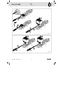
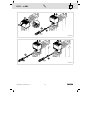
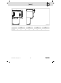
L−force Communication Ä.IEbä EDK84AYCPM .IEb Montageanleitung Mounting Instructions Instructions de montage Instrucciones para el montaje Istruzioni per il montaggio PROFIBUS E84AYCPM Kommunikationsmodul Communication module Module de communication Módulo de comunicación Modulo di comunicazione l , } 0 V } , , , , , Lesen Sie zuerst diese Anleitung und die Dokumentationen auf der im Lieferumfang des Grundgerätes enthaltenen CD−ROM, bevor Sie mit den Arbeiten beginnen! Beachten Sie die enthaltenen Sicherheitshinweise. Please read these instructions and the documentation on the CD−ROM supplied together with the basic device before you start working! Observe the safety instructions given therein. Avant de commencer les opérations, lisez tout d’abord le présent manuel d’utilisation ainsi que la documentation présente sur le cédérom comprise dans la livraison de l’appareil de base ! Respectez les consignes de sécurité indiquées. Antes de empezar con los trabajos, lea detenidamente estas instrucciones y la documentación que se encuentra en el CD−ROM suministrado junto con el equipo básico. Observe las instrucciones de seguridad correspondientes. Prima di utilizzare l’apparecchiatura, leggere le istruzioni contenute nel presente manuale e la documentazione sul CD−ROM fornito in dotazione con il modulo asse. Osservare le note di sicurezza. EDK84AYCPM DE/EN/FR/ES/IT 7.0 2 l } ( , Stop! Das Kommunikationsmodul enthält elektronische Bauteile, die durch elektrostatische Entladung beschädigt oder zerstört werden können. Treffen Sie vor dem Berühren des Moduls geeignete Maßnahmen zum Schutz der Bauteile. ( Stop! The communication module contains electronic components that may be damaged or destroyed through electrostatic discharge. Take appropriate measures to protect the components before touching the communication module. ( Stop! Le module de communication contient des composants électroniques qui peuvent être endommagés ou détruits par les décharges électrostatiques. Avant d’entrer en contact avec le module, prenez les mesures appropriées pour assurer la protection des composants. ( ¡Alto! El módulo de comunicación contiene piezas electrónicas que pueden resultar dañadas o destruidas por descargas electroestáticas. Antes de entrar en contacto con el módulo, tome las medidas necesarias para proteger las piezas. ( Stop! Il modulo di comunicazione contiene componenti elettronici che possono essere danneggiati o distrutti da scariche elettrostatiche. Prima di toccare il modulo, si raccomanda di prendere tutte le misure necessarie per proteggere i componenti. EDK84AYCPM DE/EN/FR/ES/IT 7.0 3 l ) , ) E84YCPM001J EDK84AYCPM DE/EN/FR/ES/IT 7.0 4 l 0.25, 0.37 kW ! 1 0.25, 0.37 kW 1 ! E84YCPM002D E84YCPM002E EDK84AYCPM DE/EN/FR/ES/IT 7.0 5 l 0.55 ... x kW ! 1 0.55 ... x kW E84YCPM002A E84YCPM002B EDK84AYCPM DE/EN/FR/ES/IT 7.0 6 l S200 − X201 − LED 2 S200 − X201 − LED 2 E84YCPM001C Address S200 «64» «32» «16» «8» «4» «2» «1» 1 OFF OFF OFF OFF OFF OFF ON ... ... ... ... ... ... ... ... ON ON ON ON ON ON OFF 126 I Address 23: «1» + «2» + «4» + «16» = ON EDK84AYCPM DE/EN/FR/ES/IT 7.0 7 l S200 − X201 − LED X201 1 2 3 4 5 6 7 8 9 2 Pin Designation Description 1 − − 2 − − 3 RxD/TxD−P Data line B (received data / transmitted data, plus) 4 RTS Request To Send (received data / transmitted data, no differential signal) 5 M5V2 Data ground (ground to 5V) 6 P5V2 DC 5 V / 30 mA (bus termination) 7 − − 8 RxD/TxD−N Data line A (received data / transmitted data, minus) 9 − − Baud rate Max. cable length 9.6 ... 93.75 kbit/s 1200 m 187.5 kbit/s 1000 m 500 kbit/s 400 m 1500 kbit/s 200 m 3000 ... 12000 kbit/s 100 m Cable Cores Double twisted, insulated and shielded Core diameter > 0.64 mm Core cross−section > 0.34 mm2 Loop resistance < 110 W/km Specific resistance 135 ... 165 W/km (f = 3 ... 20 MHz) Capacitance per unit length £ 30 nF/km EDK84AYCPM DE/EN/FR/ES/IT 7.0 8 l S200 − X201 − LED ) 2 Hinweis! Busabschluss−Widerstand aktivieren Beim ersten und letzten physikalischen Busteilnehmer müssen Sie einen Busabschluss−Widerstand aktivieren. Der Busabschluss−Widerstand ist im Busanschluss−Stecker eingebaut und wird mit einem Schalter aktiviert. ) Note! Activating the bus terminating resistor Activate the bus terminating resistor of the first and the last physical bus device. The bus terminating resistor is integrated into the bus connector and is activated using a switch. ) Remarque importante ! Activation de la résistance d’extrémité de bus Il faut activer la résistance d’extrémité de bus sur les premier et dernier participants au bus. Intégrée dans la prise de raccordement au bus, la résistance d’extrémité de bus est activée à l’aide d’un commutateur. ) ¡Nota! Activar resistencia terminal de bus En el primer y último dispositivo físico del bus debe activarse una resistencia terminal de bus. La resistencia terminal de bus está montada en el conector del bus y se activa mediante un interruptor. ) Avvertenza: Attivazione della resistenza di terminazione bus In corrispondenza del primo e dell’ultimo nodo fisico del bus è necessario attivare una resistenza di terminazione bus. Tale resistenza è integrata nel connettore di collegamento al bus e si attiva mediante switch. EDK84AYCPM DE/EN/FR/ES/IT 7.0 9 l [mm] 3 [mm] 3 E84YCPM001B E84AYCPM a b c c1 [mm] [mm] [mm] [mm] 67 50 50 3 EDK84AYCPM DE/EN/FR/ES/IT 7.0 10 l Q © 03/2012 F ( Ê ü Lenze Drives GmbH Postfach 10 13 52 D−31763 Hameln Germany +49(0)5154/ 82−0 +49(0)5154/ 82−28 00 [email protected] Service Lenze Service GmbH Breslauer Straße 3 D−32699 Extertal Germany ( Ê 008000/ 2446877 (24 h helpline) +49(0)5154/ 82−11 12 [email protected] www.Lenze.com EDK84AYCPM § .IEb § DE/EN/FR/ES/IT § 7.0 § TD23 10 9 8 7 6 5 4 3 2 1