1
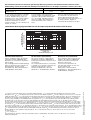
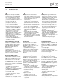
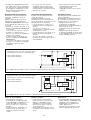
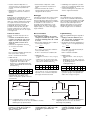
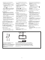
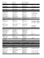
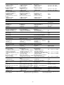
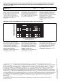
21 027-03 PNOZ X7P 4 4 4 D Betriebsanleitung GB Operating instructions F Manuel d'utilisation Sicherheitsbestimmungen 4 4 4 E Instrucciones de uso I Istruzioni per l`uso NL Gebruiksaanwijzing Safety Regulations Conseils préliminaires • Das Gerät darf nur von Personen installiert und in Betrieb genommen werden, die mit dieser Betriebsanleitung und den geltenden Vorschriften über Arbeitssicherheit und Unfallverhütung vertraut sind. • Beachten Sie die VDE- sowie die örtlichen Vorschriften, insbesondere hinsichtlich Schutzmaßnahmen. • Beim Transport, bei der Lagerung und im Betrieb die Bedingungen nach EN 600682-78 einhalten (s. technische Daten). • Durch Öffnen des Gehäuses oder eigen-mächtige Umbauten erlischt jegliche Gewährleistung. • Montieren Sie das Gerät in einen Schaltschrank; Staub und Feuchtigkeit können sonst zu Beeinträchtigungen der Funktionen führen. • Sorgen Sie an allen Ausgangskontakten bei kapazitiven und induktiven Lasten für eine ausreichende Schutzbeschaltung. • The unit may only be installed and operated by personnel who are familiar with both these instructions and the current regulations for safety at work and accident prevention. • Follow CEN and local regulations especially as regards preventative measures. • Transport, storage and operating conditions should all conform to EN 60068-2-78 (s. technical data). • Any guarantee is void following opening of the housing or unauthorised modifications. • The unit should be panel mounted, otherwise dampness or dust could lead to function impairment. • Adequate protection must be provided on all output contacts with capacitive and inductive loads. • La mise en oeuvre de l'appareil doit être effectuée par une personne spécialisée en installations électriques, en tenant compte des prescriptions des différentes normes applicables (NF, EN, VDE..), notamment au niveau des risques encourus en cas de défaillance de l'équipement électrique. • Respecter les exigences de la norme EN 60068-2-78 lors du transport, du stockage et de l'utilisation de l'appareil. • L'ouverture du boîtier annule automatiquement la clause de garantie. • Installez le relais dans une armoire électrique à l'abri de la poussière et de l'humidité. • Assurez-vous du pouvoir de coupure des contacts de sortie en cas de charges inductives ou capacitives Bestimmungsgemäße Verwendung Intended Applications Domaine d'utilisation Das Sicherheitsschaltgerät dient dem sicherheitsgerichteten Unterbrechen eines Sicherheitsstromkreises. Das Sicherheitsschaltgerät erfüllt Forderungen der EN 60947-5-1, EN 60204-1 und VDE 01131 und darf eingesetzt werden in Anwendungen mit • Not-Halt-Tastern • Schutztüren Das Gerät ist nicht für die Absicherung von berührungslosen Verdeckungen geeignet, da kein dynamischer Start möglich ist. The safety relay provides a safety-related interruption of a safety circuit. The safety relay meets the requirements of EN 60947-5-1, EN 60204-1 and VDE 01131 and may be used in applications with • E-STOP pushbuttons • Safety gates The unit is not suitable for use with noncontact guards, as a dynamic start is not possible. Le bloc logique de sécurité sert à interrompre en toute sécurité un circuit de sécurité. Le bloc logique de sécurité satisfait aux exigences des normes EN 60947-5-1, EN 60204-1 et VDE 0113-1 et peut être utilisé dans des applications avec des • poussoirs d’arrêt d’urgence • protecteurs mobiles L'appareil n'est pas adapté à la surveillance de barrières immatérielles car une validation dynamique n'est pas possible. Gerätebeschreibung Description Description de l'appareil Das Sicherheitsschaltgerät ist in einem S99-Gehäuse untergebracht. Das PNOZ X7P 24 V AC/DC kann mit 24 V AC oder 24 V DC betrieben werden. Das PNOZ X7P AC kann mit 110 - 120 oder 230 - 240 V AC betrieben werden. Zwischen dem Not-Halt-Taster und dem Starttaster besteht bei PNOZ X7P AC eine galvanische Trennung. Merkmale: • Relaisausgänge: 2 Sicherheitskontakte (Schließer), zwangsgeführt • Anschlussmöglichkeit für - Not-Halt-Taster - Starttaster • Statusanzeige • Rückführkreis zur Überwachung externer Schütze The relay is enclosed in a 22.5 mm, S-99 housing. The PNOZ X7P 24 V AC/DC is a dual-voltage unit and the PNOZ X7P AC is available with the following voltages: 110 120 or 230 - 240 VAC. There is galvanic isolation between the E-STOP button and the reset button on the PNOZ X7P AC version. Features: • Relay outputs: 2 (N/O) safety contacts, positive-guided • Connections for - E-STOP button - Reset button • Status Indicators • Feedback control loop for monitoring external relays / contactors Le bloc logique PNOZ X7P est inséré dans un boîtier S-99. Le PNOZ X7P 24V AC/DC peut être alimenté en 24 VAC ou 24 VDC. Le PNOZ X7P AC peut être alimenté en 110 - 120 ou 230 - 240 VAC. Le PNOZ X7P AC dispose d'une isolation galvanique entre le BP AU et le circuit de réarmement. Particularités : • contacts de sortie : 2 contacts à fermeture de sécurité, contacts liés • raccordement pour - Poussoir AU ou capteur - Poussoir de réarmement • LEDs de visualisation • boucle de retour pour l'auto-contrôle des contacteurs externes Das Schaltgerät erfüllt folgende Sicherheitsanforderungen: • Die Schaltung ist redundant mit Selbstüberwachung aufgebaut. • Die Sicherheitseinrichtung bleibt auch bei Ausfall eines Bauteils wirksam. • Bei jedem Ein-Aus-Zyklus der Maschine wird automatisch überprüft, ob die Relais der Sicherheitseinrichtung richtig öffnen und schließen. The relay complies with the following safety requirements: • The circuit is redundant with built-in selfmonitoring. • The safety function remains effective in the case of a component failure. • The correct opening and closing of the safety function relays is tested automatically in each on-off cycle. -1- Le bloc logique PNOZ X7P répond aux exigences suivantes : • conception redondante avec autosurveillance • fonction de sécurité garantie même en cas de défaillance d'un composant électronique. • test cyclique du relais à chaque mise sous tension de la machine. Funktionsbeschreibung Function Description Description du fonctionnement Das Schaltgerät dient dem sicherheitsgerichteten Unterbrechen eines Sicherheitsstromkreises. Voraussetzung: Anlegen der Versorgungsspannung über den Not-Halt-Taster, Brücke zwischen Y1-Y2 oder Starttaster zwischen Y1 und Y2 betätigt. • Eingangskreis geschlossen (z. B. NotHalt-Taster nicht betätigt) Relais K1 und K2 gehen in Wirkstellung und halten sich selbst. Die Sicherheitskontakte 13-14/23-24 sind geschlossen. • Eingangskreis wird geöffnet (z. B. NotHalt-Taster betätigt) K1 und K2 fallen in die Ruhestellung zurück. Die Sicherheitskontakte 13-14/2324 werden redundant geöffnet. The relay provides a safety-oriented interruption of a safety circuit. Function: apply the operating voltage via the E-Stop button, link between Y1 - Y2 or activate the reset button between Y1 - Y2. • Input circuit closed (e.g. emergency stop button not operated): Relays K1 and K2 energise and latch. The safety contacts 13-14/23-24 are closed. • Input circuit opened (e.g. emergency stop button operated): K1 and K2 deenergise. The safety contacts 13-14/2324 are opened redundantly. Le bloc logique assure de façon sûre l'ouverture d'un circuit de sécurité. Préalables: tension d'alimentation présente sur poussoir AU , ponts entre Y1-Y2 ou poussoir sur Y1-Y2 actionné • circuit d'entrée fermé (par ex. poussoir AU non actionné) Les relais K1 et K2 passe en position travail et s'auto-maintiennent. Les contacts de sécurité 13-14/23-24 se ferment. • circuit d'entrée ouvert (par ex. poussoir AU actionné) K1 et K2 retombent. Les contacts de sécurité 13-14/23-24 s'ouvrent de façon redondante. A: Einschaltlogik, zyklischer Test, Steuerlogik/ Operating Logic, Cycle Test, Control Logic/ Logique d'entrée, test cyclique, logique de commande 1: Kanal 1/Channel 1/Canal 1 2: Kanal 2/Channel 2/Canal 2 Y1 Y2 13 23 14 24 K1 A1 + 1 A 2 K2 A2 Fig. 1: PNOZ X7P 24 V DC/AC Schematisches Schaltbild/Connection Diagram/Schéma de principe A: Einschaltlogik, zyklischer Test, Steuerlogik/ Operating Logic, Cycle Test, Control Logic/ Logique d'entrée, test cyclique, logique de commande 1: Kanal 1/Channel 1/Canal 1 2: Kanal 2/Channel 2/Canal 2 A1 A2 Y1 Y2 13 23 14 24 K1 1 ~ G A 2 = K2 Fig. 2: PNOZ X7P AC Schematisches Schaltbild/Connection Diagram/Schéma de principe Betriebsarten: • Einkanaliger Betrieb: Eingangsbeschaltung nach VDE 0113 und EN 60204, keine Redundanz im Eingangskreis. Erdschlüsse im Tasterkreis werden erkannt. • Automatischer Start: Gerät ist aktiv, sobald der Eingangskreis geschlossen ist. • Manueller Start: Gerät ist erst dann aktiv, wenn ein Starttaster betätigt wird. • Kontaktvervielfachung und Kontaktverstärkung durch Anschluss von Kontakterweiterungsblöcken und externen Schützen. Operating Modes • Single-channel operation: Input wiring according to VDE 0113 and EN 60204, no redundancy in the input circuit. Earth faults are detected in the emergency stop circuit. • Automatic reset: unit is active, as soon as the input circuit is closed. • Manual reset: unit is only active, when a reset button has been pressed. • Increase in the number of contacts available by connecting expander modules and external contactors / relays. -2- Mode de fonctionnements : • Commande par 1 canal : conforme aux prescriptions de la norme EN 60204, pas de redondance dans le circuit d'entrée.La mise à la terre du circuit d'entrée est détectée. • Réarmement automatique : le relais est activé dès la fermeture du circuit d'entrée. • Réarmement manuel : le relais n'est activé qu'après une impulsion sur le poussoir de réarmement. • Augmentation du nombre de contacts ou du pouvoir de coupure par l'utilisation de blocs d’extension de contacts et contacteurs externes Montage Installation Montage Das Sicherheitsschaltgerät muss in einen Schaltschrank mit einer Schutzart von mind. IP54 eingebaut werden. Zur Befestigung auf einer Normschiene hat das Gerät ein Rastelement auf der Rückseite. Sichern Sie das Gerät bei Montage auf einer senkrechten Tragschiene (35 mm) durch ein Halteelement wie z. B. Endhalter oder Endwinkel. The safety relay must be panel mounted (min. IP54). There is a notch on the rear of the unit for DIN-Rail attachment. If the unit is installed on a vertical mounting rail (35 mm), ensure it is secured using a fixing bracket such as end bracket. Le relais doit être monté dans l'armoire électrique ayant au min. un indice de protection IP54. Sa face arrière permet un montage rapide sur rail DIN. Immobilisez l'appareil monté sur un rail DIN vertical (35 mm) à l'aide d'un élément de maintien comme par ex. un support ou une équerre terminale. Inbetriebnahme Operation Mise en oeuvre Beachten Sie bei der Inbetriebnahme: • Vor die Ausgangskontakte eine Sicherung (6 A flink oder 4 A träge) schalten, um das Verschweißen der Kontakte zu verhindern. • Berechnung der max. Leitungslänge Imax im Eingangskreis: Please note for operation: • To prevent contact welding, a fuse (6 A quick / 4 A slow acting) must be connected before the output contacts. • Calculate the max. cable runs lmax in the input circuit: Remarques préléminaires : • Protection des contacts de sortie par des fusibles 6 A rapides ou 4 A normaux pour éviter leur soudage. • Calcular les longueurs de câblage max Imax dans le circuit d’entrée: Rlmax Imax = Rl / km Rlmax = max. Gesamtleitungswiderstand (s. technische Daten) Rl /km = Leitungswiderstand/km • PNOZ X7P AC: - Ringleitung, 1 Phase (s. Fig. 3): 1 km - Stichleitung (s. Fig. 4): max. Länge der Stichleitung ls und max. Kabelkapazität CL in Abhängigkeit der Versorgungsspannung UB: Imax = Rl / km Rlmax = Max. Total cable resistance (see technical details) Rl /km = cable resistance/km • PNOZ X7P AC: - ring circuit (Fig. 3): 1 km - branch line (Fig. 4): max. length of the branch line I s and max. capacity will depend on the supply voltage UB: UB [V] 42 UB [V] 42 48 110 115 120 230 240 Imax = Rlmax 48 110 115 120 230 240 lr UB N Rlmax = résistivité de câblage totale max. (voir les caractéristiques techniques) Rl /km = résistivité de câblage/km • PNOZ X7P AC: - Câblage en boucle (v. Fig. 3): 1 km - Câblage en dérivation (v. Fig. 4): long. max. de la dérivation ls et capacité max. dépend de la tension d'alimentation UB: UB [V] 42 48 110 115 120 230 240 CL [nF] 37,5 37,5 37,5 37,5 37,5 7,5 7,5 CL [nF] 37,5 37,5 37,5 37,5 37,5 7,5 7,5 Values for the max. capable capacity CL must be adhered to, otherwise the unit could malfunction. Respecter impérativement la capacité max. CL du câble pour prévenir un mauvais fonctionnement du relais. CL [nF] 37,5 37,5 37,5 37,5 37,5 7,5 7,5 Werte für die max. Kabelkapazität CL unbedingt einhalten, sonst kann das Gerät fehlerhaft reagieren. Rlmax Rl / km ls PNOZ X7P AC PNOZ X7P AC A1 UB A1 A2 N A2 Fig. 3: Leitungslänge lr bei Ringleitung/Cable length Ir with a ring circuit/Longueur de câblage lr en boucle Fig. 4: Leitungslänge ls der Stichleitung/Cable length Is of the branch line/Longueur câblage Is en dérivation • Keine kleinen Ströme mit Kontakten schalten, über die zuvor große Ströme geführt wurden. • Leitungsmaterial aus Kupferdraht mit einer Temperaturbeständigkeit von 60/75 °C verwenden. • Geräte unbedingt erden: - PNOZ X7P 24 V AC/DC an Anschlussklemme A2 - PNOZ X7P AC an Anschlussklemme • Low currents should not be switched across contacts across which high currents have previously been switched. • Use copper wire that can withstand 60/75 °C. • The unit must be earthed - PNOZ X7P 24 VDC/AC at the connection terminal A2 - PNOZ X7P AC at the terminal marked Nur so kann das Gerät Erdschlüsse im Stromkreis Y1-Y2 erkennen. • Angaben im Kapitel "Technische Daten" unbedingt einhalten. This enables earth faults in the circuit Y1-Y2 to be detected • Important details in the section “Technical Data” should be noted and adhered to. -3- • Ne pas commuter de faibles intensités par des contacts ayant au préalable commutés des intensités plus élevées. • Utiliser uniquement des fils de câblage en cuivre 60/75 °C. • Le PNOZ X7P doit être toujours relié à la terre : - PNOZ X7P 24 V DC/AC par la borne A2 - PNOZ X7P AC par la borne Ce câblage permet de détecter une mise à la terre du circuit Y1-Y2. • Respectez les données indiquées dans les caractéristiques techniques. Ablauf: • Not-Halt-Taster zwischen Klemme A1 des PNOZ und die Klemme L+/L1 der Versorgungsspannung anschließen. 0VSeite der Versorgungsspannung mit A2 verbinden. Die LED "Power" leuchtet. • Rückführkreis mit automatischem Start: Brücke oder externe Kontakterweiterungen an Y1-Y2 anschließen. • Rückführkreis mit manuellem Start: Starttaster an Y1-Y2 und externe Kontakterweiterungen in Reihe schalten. Die Sicherheitskontakte sind geschlossen. Die LED "CH.1/2" leuchtet. Das Gerät ist betriebsbereit. Der Starttaster kann wieder geöffnet werden. Wird der Eingangskreis geöffnet (Not-HaltTaster betätigt), öffnen die Sicherheitskontakte 13-14/23-24. Wieder aktivieren • Eingangskreis schließen. • Bei manuellem Start zusätzlich Starttaster betätigen. To operate: • Connect the E-Stop button between terminal A1 of the PNOZ and the supply L+/L1 of the operating voltage. Connect terminal A2 with the 0V side of the operating voltage. The LED “Power” is illuminated. • Feedback control loop with automatic reset: link Y1-Y2 or connect external contactors • Feedback control loop with manual reset: Connect reset button at Y1 - Y2 or connect external contactors in series The safety contacts are closed. The LED 'CH.1/CH.2' is illuminated. The unit is ready for operation. The reset button can be opened again, i.e. released. If the input circuit is opened (E-Stop activated), the safety contacts 13-14/23-24 open. Reactivation • Close the input circuit. • With manual reset, the reset button must also be pressed. Mise en oeuvre : • Câblez le contact du poussoir AU entre les bornes A1 (L+) du PNOZ X7 et le potentiel L+/L1 de la tension d'alimentation. Relier la borne A2 (L-) du PNOZ X7 au 0V de la tension d'alimentation. La LED "Power" s'allume. • Boucle de retour avec réarmement auto.: pont entre Y1-Y2 ou câblage des contacts externes. • Boucle de retour avec réarmement manuel : Branchement d'un poussoir entre les bornes Y1-Y2, en série avec les contacts externes. Les contacts de sécurité sont fermés. La LED CH.1/CH.2 est allumée. Si le circuit d'entrée est ouvert (AU actionné), les contacts 13-14/23-24 s'ouvrent. Remise en route : • fermer le circuit d'entrée • en cas de réarmement manuel, appuyer sur le poussoir Y1-Y2. 1L1 UB (L+) Y1 K3 K4 Y1 Y2 13 14 A1 Y2 K3 K4 1L2 Fig. 5: Eingangskreis einkanalig: Not-HaltBeschaltung; manueller Start/ Single channel input circuit: Emergency Stop wiring; manual reset/ Commande par 1 canal : circuit AU, avec réarmement manuel Fig. 6: Verstärkung (Vervielfältigung) der Kontakte durch externe Schütze; einkanalig; automatischer Start/Increase in the number of available contacts by connection of external contactors/relays; single channel; automatic reset/ Multiplication des contacts à l'aide de contacteurs externes; commande par 1 canal; réarmement automatique Fehler - Störungen Faults/Disturbances Erreurs - Défaillances • Erdschluss im Start-/Rückführkreis: Die Versorgungsspannung bricht zusammen und die Sicherheitskontakte werden über eine elektronische Sicherung geöffnet. Nach Wegfall der Störungsursache und Abschalten der Versorgungsspannung für ca. 1 Minute ist das Gerät wieder betriebsbereit. • Fehlfunktionen der Kontakte: Bei verschweißten Kontakten ist nach Öffnen des Eingangskreises keine neue Aktivierung möglich. • Earth fault in the reset circuit/feedback loop: Supply voltage fails and the safety contacts are opened via an electronic fuse. Once the cause of the fault has been removed and operating voltage is switched off, the unit will be ready for operation after approximately 1 minute. • Faulty contact functions: In the case of welded contacts, no further activation is possible following an opening of the input circuit. • Défaut de masseau circuit de réarmement/de boucle de retour : La tension d’alimentation chute et les contacts de sécurité sont ouverts par un fusible électronique. Une fois la cause du défaut éliminée et la tension d’alimentation coupée, l’appareil est à nouveau prêt à fonctionner après environ 1 minute. • Défaut d'un contact : en cas de collage d'un contact après ouverture du circuit d'entrée, un nouvel réarmement est impossible. -4- Abmessungen in mm/Dimensions in mm/Dimensions en mm Gehäuse mit steckbaren Federkraftklemmen/ Housing with plug-in cage spring-loaded terminals/ Boîtier avec borniers débrochables à ressort 75 (2.95") 87 (3.42") 121 (4.76") 121 (4.76") Gehäuse mit steckbaren Schraubklemmen/ Housing with plug-in screw terminals/ Boîtier avec borniers débrochables à vis 22,5 (0.88") 75 (2.95") 87 (3.42") 94 (3.70") 22,5 (0.88") 101 (3.98") Steckbare Klemmen abziehen Remove plug-in terminals Démonter les borniers débrochables Schraubendreher in Gehäuseaussparung hinter der Klemme ansetzen und Klemme heraushebeln. Klemmen nicht an den Kabeln abziehen! Insert screwdriver into the cut-out of the housing behind the terminal and lever the terminal. Do not remove the terminals by pulling the cables! Placer un tournevis derrière les bornes et sortir le bornier. Ne pas retirer les borniers en tirant sur les câbles ! Abziehen der Klemmen am Beispiel einer Schraubklemme How to remove the terminals using a screw terminal as an example Démontage d’un bornier à vis -5- Technische Daten Technical Data Caractéristiques techniques Elektrische Daten Versorgungsspannung UB PNOZ X7P AC/DC PNOZ X7P AC Spannungstoleranz Leistungsaufnahme bei UB PNOZ X7P AC/DC PNOZ X7P AC Frequenzbereich Restwelligkeit Spannung und Strom an Eingangskreis PNOZ X7P AC/DC PNOZ X7P AC Electrical data Supply Voltage UB PNOZ X7P AC/DC PNOZ X7P AC Voltage Tolerance Power consumption at UB PNOZ X7P AC/DC PNOZ X7P AC Frequency range Residual Ripple Voltage and Current at Input circuit PNOZ X7P AC/DC PNOZ X7P AC Données électriques Tension d’alimentation UB PNOZ X7P AC/DC PNOZ X7P AC Plage de la tension d’alimentation Consommation pour UB PNOZ X7P AC/DC PNOZ X7P AC Fréquence Ondulation résiduelle Tension et courant du Circuit d’entrée PNOZ X7P AC/DC PNOZ X7P AC Startkreis PNOZ X7P AC/DC PNOZ X7P AC Rückführkreis PNOZ X7P AC/DC PNOZ X7P AC Anzahl der Ausgangskontakte Sicherheitskontakte (S) Gebrauchskategorie nach EN 60947-4-1 PNOZ X7P AC/DC Reset circuit PNOZ X7P AC/DC PNOZ X7P AC Feedback loop PNOZ X7P AC/DC PNOZ X7P AC Number of output contacts Safety contacts (N/O) Utilization category in accordance with EN 60947-4-1 PNOZ X7P AC/DC Circuit de réarmement PNOZ X7P AC/DC PNOZ X7P AC Circuit de boucle de retour PNOZ X7P AC/DC PNOZ X7P AC Nombre de contacts de sortie contacts de sécurité (F) Catégorie d’utilisation selon EN 60947-4-1 PNOZ X7P AC/DC PNOZ X7P AC EN 60947-5-1(DC13: 6 Schaltspiele/Min.) PNOZ X7P AC/DC PNOZ X7P AC PNOZ X7P AC PNOZ X7P AC EN 60947-5-1 (DC13: 6 cycles/min) PNOZ X7P AC/DC EN 60947-5-1(DC13: 6 manoeuvres/min) PNOZ X7P AC/DC PNOZ X7P AC PNOZ X7P AC Kontaktmaterial Contact material Kontaktabsicherung extern External contact fuse protection EN 60947-5-1 (IK = 1 kA) EN 60947-5-1 (IK = 1 kA) Schmelzsicherung flink Blow-out fuse quick PNOZ X7P AC/DC PNOZ X7P AC/DC PNOZ X7P AC PNOZ X7P AC Schmelzsicherung träge Blow-out fuse slow PNOZ X7P AC/DC PNOZ X7P AC/DC PNOZ X7P AC PNOZ X7P AC Sicherungsautomat Safety cut-out Charakteristik Characteristic Max. Gesamtleitungswiderstand Rlmax Max. overall cable resistance Rlmax Eingangskreise input circuits PNOZ X7P AC/DC PNOZ X7P AC/DC einkanalig DC Single-channel DC einkanalig AC Single-channel AC Sicherheitstechnische Kenndaten Safety-related characteristics of der Sicherheitsausgänge the safety outputs PL nach EN ISO 13849-1 PL in accordance with EN ISO 13849-1 Kategorie nach EN 954-1 Category in accordance with EN 954-1 SIL CL nach EN IEC 62061 SIL CL in accordance with EN IEC 62061 PFH nach EN IEC 62061 PFH in accordance with EN IEC 62061 SIL nach IEC 61511 SIL in accordance with IEC 61511 PFD nach IEC 61511 PFD in accordance with IEC 61511 tM in Jahren tM in years Zeiten Times Einschaltverzögerung Switch-on delay Automatischer Start Automatic reset PNOZ X7P AC/DC PNOZ X7P AC/DC PNOZ X7P AC PNOZ X7P AC Automatischer Start nach Automatic reset after Netz-Ein Power-On PNOZ X7P AC/DC PNOZ X7P AC/DC PNOZ X7P AC PNOZ X7P AC Manueller Start Manual reset PNOZ X7P AC/DC PNOZ X7P AC/DC PNOZ X7P AC PNOZ X7P AC -6- 24 V 110 ... 120 V, 230 ... 240 V -15 ... +10 % AC: 3,0 VA, DC: 1,5 W 2,0 VA AC: 50 ... 60 Hz DC: 160 % 24 V AC/DC, 50 mA 110 - 120 V AC, 17 mA; 230 - 240 V AC, 8 mA 24 V DC, 210 mA 24 V DC, 40 mA 24 V DC, 210 mA 24 V DC, 40 mA 2 AC1: 240 V/0,01 ... 6 A/1500 VA DC1: 24 V/0,01 ... 6 A/150 W AC1: 240 V/0,01 ... 4 A/1000 VA DC1: 24 V/0,01 ... 4 A/100 W AC15: 230 V/5 A; DC13: 24 V/6 A AC15: 230 V/4 A; DC13: 24 V/4 A AgSnO2+ 0,2 µm Au Matériau contact Protection des contacts externe EN 60947-5-1 (IK = 1 kA) Fusibles rapide 6A PNOZ X7P AC/DC 4A PNOZ X7P AC Fusibles normal 4A PNOZ X7P AC/DC 4A PNOZ X7P AC 24 V AC/DC: 4 A Dijoncteur Caractéristique B/C Résistance de câblage totale max. Rlmax circuits d'entrée PNOZ X7P AC/DC Commande par 1 canal DC 15 Ohm Commande par 1 canal AC 15 Ohm Caractéristiques techniques de sécurité des sorties de sécurité PL selon EN ISO 13849-1 PL e (Cat. 4) Catégorie selon EN 954-1 Cat. 4 SIL CL selon EN IEC 62061 SIL CL 3 PFH selon EN IEC 62061 2,31E-09 SIL selon IEC 61511 SIL 3 PFD selon IEC 61511 2,03E-06 tM en années 20 Temporisations Temps de réarmement Réarmement automatique PNOZ X7P AC/DC typ. 50 ms, max. 150 ms PNOZ X7P AC typ. 230 ms, max. 700 ms Réarmement automatique après mise sous tension PNOZ X7P AC/DC typ. 50 ms, max. 150 ms PNOZ X7P AC typ. 230 ms, max. 700 ms Réarmement manuel PNOZ X7P AC/DC typ. 35 ms, max. 150 ms PNOZ X7P AC typ. 140 ms, max. 700 ms Rückfallverzögerung bei Not-Halt PNOZ X7P AC/DC PNOZ X7P AC bei Netzausfall PNOZ X7P AC/DC PNOZ X7P AC Wiederbereitschaftszeit bei max. Schaltfrequenz 1/s nach Not-Halt PNOZ X7P AC/DC PNOZ X7P AC nach Netzausfall PNOZ X7P AC/DC PNOZ X7P AC Überbrückung bei Spannungseinbrüchen Umweltdaten EMV Delay-on De-Energisation at E-STOP PNOZ X7P AC/DC PNOZ X7P AC with power failure PNOZ X7P AC/DC PNOZ X7P AC Recovery time at max. switching frequency 1/s after E-STOP PNOZ X7P AC/DC PNOZ X7P AC after power failure PNOZ X7P AC/DC PNOZ X7P AC Supply interruption before deenergisation Environmental data EMC Temps de retombée en cas d'arrêt d'urgence PNOZ X7P AC/DC PNOZ X7P AC en cas de coupure d'alimentation PNOZ X7P AC/DC PNOZ X7P AC Temps de remise en service en cas de fréquence de commutation max. 1/s arrêt d'urgence PNOZ X7P AC/DC PNOZ X7P AC après une coupure d'alimentation PNOZ X7P AC/DC PNOZ X7P AC Tenue aux micro-coupures The version of the standards current at 2004-09 shall apply -7- typ. 45 ms, max. 70 ms typ. 70 ms, max. 100 ms 50 ms 120 ms 150 ms 120 ms 20 ms Données sur l'environnement CEM Schwingungen nach EN 60068-2-6 Vibration to EN 60068-2-6 Vibrations selon EN 60068-2-6 Frequenz Frequency Frequence Amplitude Amplitude Amplitude Klimabeanspruchung Climate Suitability Conditions climatiques Luft- und Kriechstrecken nach Airgap Creepage in accordance with Cheminement et claquage selon EN 60947-1 EN 60947-1 EN 60947-1 Verschmutzungsgrad Pollution degree Niveau d'encrassement Überspannungskategorie Overvoltage category Catégorie de surtensions Bemessungsisolationsspannung Rated insulation voltage Tension assignée d'isolement BemessungsstoßspannungsRated impulse withstand voltage Tension assignée de tenue aux festigkeit chocs Umgebungstemperatur Ambient temperature Température d’utilisation Lagertemperatur Storage temperature Température de stockage Schutzart Protection type Indice de protection Einbauraum (z. B. Schaltschrank) Mounting (eg. panel) Lieu d'implantation (ex. armoire) Gehäuse Housing Boîtier Klemmenbereich Terminals Bornes Mechanische Daten Mechanical data Données mécaniques Gehäusematerial Housing material Matériau du boîtier Gehäuse Housing Boîtier Front Front panel Face avant Querschnitt des Außenleiters Cable cross section (screw Capacité de raccordement (Schraubklemmen) terminals) (borniers à vis) 1 Leiter, flexibel 1 core, flexible 1 conducteur souple 2 Leiter gleichen Querschnitts, fle- 2 core, same cross section flexible 2 conducteurs de même diamètre xibel mit Aderendhülse, ohne with crimp connectors, without souple avec embout, sans Kunststoffhülse insulating sleeve chapeau plastique ohne Aderendhülse oder mit TWIN- without crimp connectors or with souple sans embout ou avec Aderendhülse TWIN crimp connectors embout TWIN Querschnitt des Außenleiters Cable cross section (spring-loaded Capacité de raccordement (Federkraftklemmen) terminals) (borniers à ressort) flexibel ohne Aderendhülse flexible without crimp connectors souple sans embout Gehäuse mit Federkraftklemmen Housing with spring-loaded terminals Boîtier avec borniers à ressort Abisolierlänge Stripping length Longueur de dénudage Klemmstellen pro Anschluss Termination points per connection Bornes par raccordement Anzugsdrehmoment für Torque setting for screw terminals Couple de serrage (borniers à vis) Schraubklemmen Abmessungen (Schraubklemmen) Dimensions (screw terminals) Dimensions (borniers à vis) HxBxT HxWxD HxPxL Abmessungen (Federkraftklemmen) Dimensions (spring-loaded Dimensions (borniers à ressort) HxBxT terminals) H x W x D H xLxP Einbaulage Fitting Position Position de travail Gewicht Weight Poids PNOZ X7P AC/DC PNOZ X7P AC/DC PNOZ X7P AC/DC PNOZ X7P AC PNOZ X7P AC PNOZ X7P AC Es gelten die 2004-09 aktuellen Ausgaben der Normen typ. 45 ms, max. 70 ms typ. 70 ms, max. 100 ms EN 60947-5-1, EN 61000-6-2 10 ... 55 Hz 0,35 mm EN 60068-2-78 2 III 250 V 4 kV -10 ... + 55 °C -40 ... +85 °C IP54 IP40 IP20 PPO UL 94 V0 ABS UL 94 V0 0,25 ... 2,5 mm2, 24 - 12 AWG 0,25 ... 1 mm2, 24 - 16 AWG 0,20 ... 1,5 mm2, 24 - 16 AWG 0,20 ... 1,5 mm2, 24 - 16 AWG 8 mm 2 0,5 Nm 94 x 22,5 x 121 mm 101 x 22,5 x 121 mm beliebig/any/indifférente 190 g 230 g Se référer à la version des normes en vigeur au 2004-09. Konventioneller thermischer Strom bei gleichzeitiger Belastung mehrerer Kontakte/Conventional thermal current while loading several contacts/Courant thermique conventionnel en cas de charge sur plusieurs contacts (AC1, DC1) Anzahl der Kontakte/number of contacts/nombre des contacts PNOZ X7P AC/DC: Ith PNOZ X7P AC: Ith Um ein Versagen der Geräte zu verhindern, an allen Ausgangskontakten für eine ausreichende Funkenlöschung sorgen. Bei kapazitiven Lasten sind eventuell auftretende Stromspitzen zu beachten. Bei DCSchützen Freilaufdioden zur Funkenlöschung einsetzen, um die Lebendauer der Schütze zu erhöhen. 2 4,0 A 3,0 A To prevent failure of the unit, all output contacts should be fused adequately. With capacative loads, possible current peaks are to be avoided. With DC contactors/ relays use suitable spark suppression to ensure extended life of the contactors/ relays. 1 4,0 A 4,0 A Prévoir un dispositif d’extinction d’arc sur les contacts de sortie pour éviter un éventuel disfonctionnement du relais. Tenir compte des pointes d’intensité en cas de charge capacitive. Equiper les contacteurs DC de diodes de roue libre . Lebensdauer der Ausgangsrelais/Service Life of Output relays/Durée de vie des relais de sortie AC15: 230 V DC1: 24 V DC13: 24 V AC1: 230 V 1 0.1 10 100 1000 Schaltspielzahl x 103 Cycles x 103 Nombre de manvres x 103 10000 EG-Konformitätserklärung: EC Declaration of Conformity: Déclaration de conformité CE : Diese(s) Produkt(e) erfüllen die Anforderungen der Richtlinie 2006/42/EG über Maschinen des europäischen Parlaments und des Rates. Die vollständige EG-Konformitätserklärung finden Sie im Internet unter www.pilz.com Bevollmächtigter: Norbert Fröhlich, Pilz GmbH & Co. KG, Felix-Wankel-Str. 2, 73760 Ostfildern, Deutschland This (these) product(s) comply with the requirements of Directive 2006/42/EC of the European Parliament and of the Council on machinery. The complete EC Declaration of Conformity is available on the Internet at www.pilz.com Authorised representative: Norbert Fröhlich, Pilz GmbH & Co. KG, FelixWankel-Str. 2, 73760 Ostfildern, Germany Ce(s) produit(s) satisfait (satisfont) aux exigences de la directive 2006/42/CE relative aux machines du Parlement Européen et du Conseil. Vous trouverez la déclaration de conformité CE complète sur notre site internet www.pilz.com Représentant : Norbert Fröhlich, Pilz GmbH & Co. KG, Felix-Wankel-Str. 2, 73760 Ostfildern, Allemagne A Pilz Ges.m.b.H., ✆ 01 7986263-0, Fax: 01 7986264, E-Mail: [email protected] AUS Pilz Australia, ✆ 03 95446300, Fax: 03 95446311, E-Mail: B L Pilz Belgium, ✆ 09 3217570, Fax: 09 3217571, E-Mail: [email protected] BR Pilz do Brasil, ✆ 11 4337-1241, Fax: 11 4337-1242, [email protected] CH Pilz lndustrieelektronik GmbH, ✆ 062 88979-30, Fax: 062 88979-40, E-Mail: [email protected] DK Pilz Skandinavien K/S, E-Mail: [email protected] ✆ 74436332, Fax: 74436342, E-Mail: [email protected] E Pilz lndustrieelektronik S.L., ✆ 938497433, Fax: 938497544, E-Mail: [email protected] F Pilz France FIN Pilz Skandinavien K/S, ✆ 09 27093700, Fax: 09 27093709, E-Mail: Electronic, ✆ 03 88104000, Fax: 03 88108000, E-Mail: [email protected] GB Pilz Automation Technology, ✆ 01536 460766, Fax: 01536 460866, E-Mail: [email protected] I Pilz ltalia Srl, ✆ 031 789511, [email protected] IRL Pilz Ireland Industrial Automation, ✆ 021 4346535, Fax: 021 4804994, E-Mail: [email protected] J Pilz Japan Co., Fax: 031 789555, E-Mail: [email protected] MEX Pilz de Mexico, S. de R.L. de C.V., ✆ 55 5572 1300, Fax: 55 5572 4194, E-Mail: Ltd., ✆ 045 471-2281, Fax: 045 471-2283, E-Mail: [email protected] NL Pilz Nederland, ✆ 0347 320477, Fax: 0347 320485, E-Mail: [email protected] NZ Pilz New Zealand, ✆ 09- 6345-350, Fax: [email protected] P Pilz Industrieelektronik S.L., ✆ 229407594, Fax: 229407595, E-Mail: [email protected] PRC Pilz China Representative 352, E-Mail: [email protected] ROK Pilz Korea, ✆ 031 8159541, Fax: 031 8159542, E-Mail: [email protected] Office, ✆ 021 62494658, Fax: 021 62491300, E-Mail: [email protected] SE Pilz Skandinavien K/S, ✆ 0300 13990, Fax: 0300 30740, E-Mail: [email protected] TR Pilz Elektronik Güvenlik Ürünleri ve Hizmetleri Tic. Ltd. Şti., ✆ 0224 2360180, Fax: 0224 2360184, E-Mail: [email protected] USA Pilz Automation Safety L.P., ✆ 734 354-0272, Fax: 734 354-3355, E-Mail: [email protected] www www.pilz.com D Pilz GmbH & Co. KG, Sichere Automation, Felix-Wankel-Straße 2, 73760 Ostfildern, Deutschland, ✆ +49 711 3409-0, Fax: +49 711 3409-133, E-Mail: [email protected] -8- Originalbetriebsanleitung/Original instructions/Notice originale 21 027-03, 2010-01 Printed in Germany Nennbetriebstrom (A) Nominal operating current (A) Courant coupé (A) 10 21 027-03 PNOZ X7P 4 4 4 E Instrucciones de uso I Istruzioni per l`uso NL Gebruiksaanwijzing Prescripciones de seguridad Norme di sicurezza Veiligheidsvoorschriften • El dispositivo tiene que ser instalado y puesto en funcionamiento exclusivamente por personas que estén familiarizadas, tanto con estas instrucciones de uso como con las prescripciones vigentes relativas a la seguridad en el trabajo y a la prevención de accidentes. • Hay que observar tanto las prescripciones VDE como las prescripciones locales, especialmente en lo que se refiere a las medidas de protección. • Durante el transporte, el almacenaje y el funcionamiento hay que atenerse a las condiciones conforme a EN 60068-2-78 (ver datos técnicos). • La garantía se pierde en caso de que se abra la carcasa o se lleven a cabo modificaciones por cuenta propia. • Montar el dispositivo dentro de un armario de distribución; en caso contrario es posible que el polvo y la suciedad puedan afectar el funcionamiento. • Hay que cuidar de que haya un conexionado de seguridad suficiente en todos los contactos de salida con cargas capacitivas e inductivas. • Il dispositivo può venire installato e messo in funzione solo da persone che hanno acquisito familiarità con le presenti istruzioni per l’uso e le disposizioni vigenti in materia di sicurezza di lavoro e antinfortunistica. • Osservare le disposizioni della VDE nonché le norme locali, soprattutto per quanto riguarda le misure preventive di protezione. • Durante il trasporto, l’immagazzinamento e il funzionamento attenersi alle condizioni prescritte dalla norma EN 60068-2-78 (v. Dati tecnici). • Se viene aperto l’alloggiamento oppure se vengono apportate delle modifiche in proprio decade qualsiasi diritto di garanzia. • Montare il dispositivo in un armadio elettrico; altrimenti la polvere e l’umidità possono pregiudicare le funzioni. • Occorre dotare tutti i contatti di uscita dei carichi capacitivi e induttivi con un circuito di sicurezza sufficiente. • Het apparaat mag uitsluitend worden geïnstalleerd en in bedrijf genomen door personen die vertrouwd zijn met deze gebruiksaanwijzing en met de geldende voorschriften op het gebied van arbeidsveiligheid en ongevallenpreventie. • Neemt u de van toepassing zijnde Europese richtlijnen en de plaatselijke voorschriften in acht, in het bijzonder m.b.t. veiligheidsmaatregelen. • Neemt u bij transport, bij opslag en in bedrijf de richtlijnen volgens EN 60068-278 in acht (zie technische gegevens). • Het openen van de behuizing of het eigenmachtig veranderen van de schakeling heeft verlies van de garantie tot gevolg. • Monteert u het apparaat in een schakelkast. Stof en vochtigheid kunnen anders de werking nadelig beïnvloeden. • Zorg bij capacitieve of inductieve belasting van de uitgangscontacten voor adequate contactbeschermingsmaatregelen. Campo de aplicación adecuado Uso previsto Toegelaten applicaties El dispositivo sirve para la interrupción orientada a la seguridad de un circuito de corriente de seguridad. El dispositivo de seguridad cumple los requisitos de las normas EN 60947-5-1, EN 60204-1 y VDE 0113-1 y puede utilizarse en aplicaciones con • pulsadores de parada de emergencia • puertas protectoras El dispositivo no es adecuado para el aseguramiento de coberturas sin contacto, ya que no es posible un arranque dinámico. Il modulo di sicurezza consente l'interruzione sicura di un circuito di sicurezza. Il modulo di sicurezza risponde ai requisiti secondo EN 60947-5-1, EN 60204-1 e VDE 0113-1 e può essere utilizzato in applicazioni con • pulsanti di arresto d'emergenza • ripari mobili Il dispositivo non è adatto a garantire la protezione di barriere senza contatto, poiché non è possibile nessun start dinamico. Het veiligheidsrelais dient om een veiligheidscircuit veilig te onderbreken. Het veiligheidsrelais voldoet aan de eisen van EN 60947-5-1, EN 60204-1 en VDE 0113-1 en mag worden gebruikt in toepassingen met • noodstopknoppen • hekken Het apparaat is niet geschikt voor contactloze afschermingen omdat er geen dynamische start mogelijk is. Descripción del dispositivo Descrizione del dispositivo Apparaatbeschrijving El dispositivo de seguridad se encuentra montado dentro de una carcasa S-99. El PNOZ X7P 24 V AC/DC puede funcionar con 24 V CA o 24 V CC. El PNOZ X7P AC puede funcionar con 110 - 120 ó 230 240 V CA. En el PNOZ X7P AC existe una separación galvánica entre el pulsador de PARADA DE EMERGENCIA y el pulsador de rearme. Características: • Salidas de relé: dos contactos de seguridad (contacto normalmente abierto), de guía forzosa • Posibilidades de conexión para pulsador de PARADA DE EMERGENCIA y pulsador de rearme • Indicación de estado • Circuito de realimentación para la supervisión de contactores externos El dispositivo cumple los requerimientos de seguridad siguientes: • El cableado está estructurado de modo redundante con autosupervisión. Il modulo di sicurezza è inserito in un alloggiamento S-99. Il PNOZ X7P 24 V ADC/DC può essere alimentato con corrente da 24 V CA oppure 24 V CC. Il PNOZ X7P AC può essere alimentato con corrente da 110-120 o 230-240 V CA. Tra il pulsante di arresto di emergenza e il pulsante di start del PNOZ X7P AC è prevista una separazione galvanica. Caratteristiche: • Uscite relè: due contatti di sicurezza (contatto NA), con contatti guidati • Possibilità di collegamento a pulsante di arresto di emergenza e pulsante di start • Visualizzazione di stato • Circuito di retroazione per il controllo di relè esterni Il dispositivo elettrico risponde ai seguenti requisiti di sicurezza: • Il circuito è strutturato in modo ridondante con autocontrollo. • Il dispositivo di sicurezza funziona anche in caso di guasto di un componente. Het veiligheidsrelais is in een S-99 behuizing ondergebracht. De PNOZ X7P 24 V AC/DC kan met 24 V AC of 24 V DC gebruikt worden. De PNOZ X7P AC kan met 110-120 of 230-240 V CA gebruikt worden. Tussen de noodstopknop en de startknop bestaat bij PNOZ X7P AC een galvanische scheiding. Kenmerken: • Relaisuitgangen: 2 veiligheidscontacten (maak), mechanisch gedwongen • Aansluitmogelijkheid voor noodstopknoppen en startknop • Statusweergave • Terugkoppelcircuit voor de bewaking van externe magneetschakelaars Het relais voldoet aan de volgende veiligheidseisen: • De schakeling is redundant met zelfbewaking opgebouwd. • Ook bij uitvallen van een component blijft de veiligheidsschakeling werken. -9- • El equipo de seguridad permanece activo aún cuando falle uno de los componentes. • Con cada ciclo de conexión/desconexión de la máquina se comprueba si los relés del dispositivo de seguridad abren y cierran correctamente. • Per ciascun ciclo di accensione/ spegnimento della macchina, viene eseguita la verifica automatica della corretta apertura e chiusura dei relè del dispositivo di sicurezza. • Bij elke aan/uit-cyclus van de machine wordt automatisch getest of de relaiscontacten van de veiligheidsvoorziening correct openen en sluiten. Descripción del funcionamiento Descrizione del funzionamento Functiebeschrijving El dispositivo sirve para interrumpir por razones de seguridad un circuito de seguridad. Requisito: Aplicación de la tensión de alimentación a través del pulsador de PARADA DE EMERGENCIA, puente entre Y1-Y2 o pulsador de rearme entre Y1 y Y2 accionado. • El circuito de entrada está cerrado (p. ej. pulsador de PARADA DE EMERGENCIA no accionado) Los relés K1 y K2 se ponen en posición de trabajo y se mantienen por si mismos. Los contactos de seguridad 1314/23-24 están cerrados. • Se abre el circuito de entrada (p. ej. al accionar el pulsador de PARADA DE EMERCENCIA) Los relés K1 y K2 regresan a la posición de reposo. Los contactos de seguridad 13-14/23-24 se abren de forma redundante. Il modulo consente l’interruzione di un circuito di sicurezza. Condizioni preliminari: tensione di alimentazione presente sul pulsante di arresto di emergenza, ponticelli tra Y1-Y2 o pulsante start tra Y1 e Y2 attivati. • Il circuito di ingresso è chiuso (p. es. pulsante di arresto di emergenza non azionato) I relè K1 e K2 si eccitano e si automantengono. I contatti di sicurezza 13-14/23-24 sono chiusi. • Il circuito di ingresso viene aperto (p. es. pulsante di arresto di emergenza azionato) K1 e K2 si diseccitano. I contatti di sicurezza 13-14/23-24 vengono aperti in modo ridondante. Het relais dient om een veiligheidscircuit veilig te onderbreken. Eis: Aansluiten op voedingsspanning via de noodstopknop, brug tussen Y1-Y2 of startknop tussen Y1 en Y2 bediend. • Ingangscircuit gesloten (b.v. noodstopknop niet bediend) Relais K1 en K2 worden bekrachtigd en nemen zichzelf over. De veiligheidscontacten 13-14/23-24 zijn gesloten. • Ingangscircuit wordt geopend (b.v. noodstopknop bediend): K1 en K2 vallen af. De veiligheidscontacten 13-14/23-24 worden redundant geopend. A: Lógica de conexión, test cíclico, lógica de control/ Logica di inserzione, test ciclico, logica di controllo/ Inschakellogica, cyclische test, besturingslogica 1: canal 1/canale 1/kanaal 1 2: canal 2/canale 2/kanaal 2 Y1 Y2 13 23 14 24 13 23 14 24 K1 A1 + A 1 2 K2 A2 Fig. 1: PNOZ X7P 24 V DC/AC - Plano de conexiones esquemático/Schema di collegamento/Intern schema A: Lógica de conexión, test cíclico, lógica de control/ Logica di inserzione, test ciclico, logica di controllo/ Inschakellogica, cyclische test, besturingslogica A1 A2 Y1 Y2 K1 1: canal 1/canale 1/kanaal 1 2: canal 2/canale 2/kanaal 2 A ~ G 1 2 = K2 Fig. 2: PNOZ X7P AC - Plano de conexiones esquemático/Schema di collegamento/Intern schema Modos de funcionamiento: • Funcionamiento monocanal: Conexionado de entrada según VDE 0113 y EN 60204, sin redundancia en el circuito de entrada. Se detectan los defectos a tierra en los contactos del pulsador. • Rearme automático: El dispositivo se encuentra activo en cuanto que el circuito de entrada se encuentra cerrado. Modalità operative: • Funzionamento a canale singolo: rispetto prescrizioni secondo norma VDE 0113 e EN 60204, nessuna ridondanza nel circuito di ingresso. Riconoscimento guasti a terra nel circuito del pulsante. • Start automatico: il dispositivo è attivo non appena il circuito di ingresso viene chiuso. - 10 - Bedrijfsmodi: • Eenkanalig bedrijf: Ingangsschakeling volgens VDE 0113 en EN 60204, geen redundantie in het ingangscircuit. Aardsluitingen in het ingangscircuit worden gedetecteerd. • Automatische start: apparaat is actief, zodra het ingangscircuit gesloten is. • Rearme manual: El dispositivo se encuentra activo sólo después de que se haya accionado un pulsador de rearme. • Multiplicación y refuerzo de contactos mediante la conexión de contactores externos. • Start manuale: il dispositivo è attivo quando viene attivato un pulsante di start. • Aumento del numero di contatti e aumento della portata dei contatti tramite collegamento di relè esterni. • Handmatige start: apparaat is pas dan actief, als een startknop bediend wordt. • Contactvermeerdering en contactversterking door aansluiten van externe magneetschakelaars. Montaje Montaggio Montage El dispositivo de seguridad tiene que ser montado dentro de un armario de distribución con un grado de protección de IP54 como mínimo. El dispositivo dispone en su parte trasera de un elemento de encaje para la fijación a una guía normalizada. Al montarlo en una guía portadora vertical (35 mm) hay que asegurar el dispositivo por medio de un elemento de soporte, tal como un soporte o un ángulo final. Il modulo di sicurezza deve venire montato in un armadio elettrico con un grado di protezione di almeno IP54. Per il fissaggio su di una guida DIN il dispositivo è dotato di un elemento a scatto sul retro. Al montaggio fissare il dispositivo su una guida verticale (35 mm) a mezzo di un supporto quale p. es. staffa di fissaggio o angolo terminale. Het veiligheidsrelais moet ingebouwd worden in een schakelkast die minimaal voldoet aan IP54. Bevestiging op een DINrail is mogelijk via de daarvoor bestemde relaisvoet op de achterzijde van het apparaat. Bij montage op een verticale draagrail (35 mm) moet het apparaat worden vastgezet met een eindsteun. Puesta en marcha Messa in funzione Ingebruikneming Al poner en marcha hay que tener en cuenta: • Conectar un fusible antes de los contactos de salida (6 A de acción rápida o 4 A de acción lenta) con objeto de evitar la fusión de los contactos. • Cálculo de la longitud máx. de línea Imáx en el circuito de entrada: Informazioni preliminari: • Per evitare la saldatura dei contatti, collegare un fusibile (6 A rapido o 4 A ad azione ritardata) prima dei contatti di uscita. • Calcolo della lunghezza max. conduttore Imaxnel circuito di ingresso: Neem bij ingebruikneming het volgende in acht: • Uitgangscontacten afzekeren (6 A snel of 4 A traag) om verkleven van de contacten te voorkomen. • Berekening van de max. kabellengte Imax (ingangs-, start- en terugkoppelcircuit): Imax = Rlmax Rl / km Rlmáx = resistencia máxima del total de la línea (véase datos técnicos) Rl /km = resistencia de línea/km • PNOZ X7P AC: - Línea en bucle, 1 fase (v. fig. 3): 1 km - Conductor de derivación (v. fig. 4): longitud máx. del conductor de derivación ls y capacidad máxima del cable CL dependiendo de la tensión de alimentación UB: UB [V] 42 48 110 115 120 230 240 CL [nF] 37,5 37,5 37,5 37,5 37,5 7,5 7,5 Respetar sin falta los valores de la capacidad máx. del cable CL, de lo contrario el dispositivo puede reaccionar erróneamente. lr UB N Imax = Rlmax Imax = Rl / km Rlmax Rl / km Rlmax = mass. resistenza del conduttore totale (vedi Dati tecnici) Rl /km = resistenza del conduttore/km Rlmax = Max. totale kabelweerstand (zie technische gegevens) Rl/km = Kabelweerstand/km • PNOZ X7P AC: - Conduttore circolare, 1 fase (v. fig. 3): 1 km - Stub line (v. fig. 4): max. lungh. stub line ls e max. capacità cavo CL in base alla tensione di alimentazione UB: • PNOZ X7P AC: - Separate kabels, 1 fase (zie fig. 3): 1 km - Aftakking (zie fig. 4): max. lengte van de aftakking ls en max. kabelcapaciteit CL afhankelijk van de voedingsspanning UB: UB [V] 42 48 110 115 120 230 240 CL [nF] 37,5 37,5 37,5 37,5 37,5 7,5 7,5 UB [V] 42 48 110 115 120 230 240 CL [nF] 37,5 37,5 37,5 37,5 37,5 7,5 7,5 I valori relativi alla capacità massima del cavo CL devono essere assolutamente rispettati, in caso contrario il dispositivo può reagire in maniera anomala. Waarden voor die max. kabelcapaciteit CL beslist opvolgen; het apparaat kan anders met storingen reageren. PNOZ X7P AC ls A1 A2 Fig. 3: Longitud de cable lr con línea en bucle/ Lunghezza del cavo lr nel caso di conduttore circolare/ Kabellengte lr bij separate kabels • No conectar corrientes pequeñas con contactos, a través de los cuales se han conducido anteriormente grandes corrientes. PNOZ X7P AC UB A1 N A2 Fig. 4: Longitud de cable ls del conductor de derivación/ Lunghezza del cavo lr nel caso di stub line/ Kabellengte ls bij aftakking • Non commutare piccole potenze con contatti attraverso i quali sono state commutate in precedenza alte potenze. - 11 - • Geen geringe stroomsterkten via contacten schakelen die tevoren grote stroomsterkten verwerkt hebben. • Utilizar para las líneas material de alambre de cobre con una resistencia a la temperatura de 60/75 °C. • Poner a tierra el dispositivo, sin falta: - PNOZ X7P 24 V AC/DC en el borne de conexión A2 - PNOZ X7P CA en el borne de conexión Sólo así puede reconocer el dispositivo contactos a tierra en el circuito Y1-Y2. • Respete sin falta las indicaciones del capítulo "Datos técnicos". Procedimiento: • Conectar el pulsador de PARADA DE EMERGENCIA entre el borne A1 del PNOZ y el borne L+/L1 de la tensión de alimentación. Unir la parte de 0V de la tensión de alimentación con A2. El LED "Power" se ilumina. • Circuito de realimentación con rearme automático: Conectar puente o contactores externos en Y1-Y2. • Circuito de realimentación con rearme manual: Conectar el pulsador de rearme en Y1-Y2, y si se desea contactores externos en serie. Los contactos de seguridad están cerrados. El LED "CH.1/2" se ilumina. El dispositivo se encuentra listo para el servicio. Es posible abrir de nuevo el pulsador de rearme. Si se abre el circuito de entrada (pulsador de PARADA DE EMERGENCIA accionado), entonces se abren los contactos de seguridad 13-14/23-24. Activar de nuevo • Cerrar circuito de entrada. • En caso de rearme manual, accionar adicionalmente el pulsador de rearme. • Per i cavi utilizzare materiale in filo di rame con una resistenza termica intorno ai 60/75 °C. • Per i dispositivi è assolutamente necessario eseguire la messa a terra: - PNOZ X7P 24 V AC/DC su morsetto di collegamento A2 - PNOZ X7P AC su morsetto di collegamento Solo in questo modo il dispositivo è in grado di identificare i guasti a terra nel circuito elettrico Y1-Y2. • Attenersi assolutamente alle indicazioni riportate al capitolo "Dati tecnici". Procedura: • Collegare il pulsante di arresto di emergenza tra il morsetto A1 del PNOZ e il morsetto L+/L1 della tensione di alimentazione. Collegare il lato 0 V della tensione di alimentazione con A2. Il LED "Power" è acceso. • Avvio automatico circuito di retroazione: collegare il ponte o contattori esterni a Y1-Y2. • Avvio manuale circuito di retroazione: collegare il pulsante start ad Y1-Y2 e, se desiderato, collegare i relè esterni in serie. I contatti di sicurezza sono chiusi. Il LED "CH.1/2" è acceso. Il dispositivo è pronto per l’uso. Il pulsante di start può nuovamente essere rilasciato. Se il circuito di ingresso è aperto (pulsante di arresto di emergenza azionato), si aprono i contatti di sicurezza 13-14/23-24. Riattivazione • Chiudere circuito di ingresso • Nel caso di avvio manuale, azionare il pulsante di start. • Kabelmateriaal van koperdraad met een temperatuurbestendigheid van 60/75 °C gebruiken. • Apparaten beslist aarden: - PNOZ X7P 24 V AC/DC aan aansluitklem A2 - PNOZ X7P AC aan aansluitklem Alleen zo kan het apparaat aardsluitingen in circuit Y1-Y2 detecteren. • Aanwijzingen in het hoofdstuk "Technische gegevens" beslist opvolgen. Instelprocedure: • Noodstopknop tussen klem A1 van de PNOZ en de klem L+/L1 van de voedingsspanning aansluiten. 0V-kant van de voedingsspanning met A2 verbinden. De LED "Power" licht op. • Terugkoppelcircuit met automatische start: Brug of externe magneetschakelaars op Y1-Y2 aansluiten. • Terugkoppelcircuit met handmatige start: Startknop op Y1-Y2 en indien gewenst externe magneetschakelaars in serie schakelen. De veiligheidscontacten zijn gesloten. De LED "CH.1/2" licht op. Het apparaat is bedrijfsklaar. De startknop kan weer geopend worden. Als het ingangscircuit geopend wordt (noodstopknop bediend), gaan de veiligheidscontact 13-14/23-24 open. Opnieuw activeren • Ingangscircuit sluiten. • Bij handmatige start bovendien startknop bedienen. 1L1 UB (L+) Y1 K3 K4 Y1 Y2 13 14 A1 K3 Y2 K4 1L2 Fig. 5: Circuito de entrada monocanal: conexionado de PARADA DE EMERGENCIA, rearme manual/Circuito di ingresso monocanale: circuito di arresto di emergenza; start manuale/Eenkanalig ingangscircuit: Noodstopschakeling; handmatige start Fig. 6: Refuerzo (multiplicación) de los contactos mediante contactores externos, monocanal, rearme automático/Aumento della portata (del numero) dei contatti mediante relè esterni; monocanale; start automatico/Versterking (vermenigvuldiging) van de contacten via externe magneetschakelaars; eenkanalig; automatische start - 12 - Errores - Fallos Errori - Guasti Fouten - Storingen • Contacto a tierra: La tensión de alimentación se colapsa y se abren los contactos de seguridad mediante un fusible electrónico. Una vez haya desaparecido la causa del error y se haya desconectado la tensión de alimentación durante aprox. 1 minuto, el dispositivo volverá a estar listo para el servicio. • Funcionamiento defectuoso de los contactos: En caso de contactos fundidos, después de abrir el circuito de entrada no es posible ninguna nueva activación. • Dispersione verso terra: La tensione di alimentazione viene interrotta e i contatti di sicurezza si aprono mediante un fusibile elettronico. Una volta rimosso la causa del gausto e interrotto la tensione di alimentazione, il dispositivo sarà pronto al funzionamento dopo circa un minuto. • Funzionamento errato dei contatti: in caso di saldatura dei contatti, dopo l’apertura dei circuiti di ingresso non è possibile nessuna nuova attivazione. • Aardsluiting: De voedingsspanning valt uit en de veiligheidscontacten worden geopend via een elektronische zekering. Na het wegvallen van de storingsoorzaak en het uitschakelen van de bedrijfsspanning voor ca. 1 minuut is het apparaat weer bedrijfsklaar. • Contactfout: Bij verkleefde contacten is na openen van het ingangscircuit geen nieuwe activering mogelijk. Dimensiones en mm (inch)/Dimensioni in mm (inch)/Afmetingen in mm (inch) Carcasa con bornes enchufables de muelle/ Custodia con morsetti estraibili a molla/ Behuizing met steekbare veerkrachtklemmen/ 121 (4.76") 121 (4.76") Carcasa con bornes de tornillo enchufables/ Custodia con morsetti estraibili a vite/ Behuizing met steekbare schroefklemmen/ 75 (2.95") 87 (3.42") 22,5 (0.88") 75 (2.95") 87 (3.42") 22,5 (0.88") 101 (3.98") 94 (3.70") Extraer las bornas enchufables Rimozione dei morsetti estraibili Steekbare klemmen uitnemen Colocar un destornillador en el hueco de la carcasa tras la borna y hacer palanca: ¡ No tirar de las bornas por el cable ! Inserire il cacciavite nell’incavo dietro il connettore e fare leva: Non estrarre il connettore tirandolo per i cavi! Plaats de schroevendraaier in de uitsparing achter de klemmen en druk de klemmen naar buiten. De klemmen verwijderen door aan de kabels te trekken! Esempio di come estrarre un connettore usando un cacciavite Als voorbeeld ziet u het verwijderen van schroefklemmen. Ejemplo de extracción en una borna de tornillo - 13 - Datos técnicos Dati tecnici Technische gegevens Datos eléctricos Tensión de alimentación UB PNOZ X7P AC/DC PNOZ X7P AC Tolerancia de tensión Consumo de energía con UB PNOZ X7P AC/DC PNOZ X7P AC Rango de frecuencia Ondulación residual Tensión y corriente en Circuito de entrada PNOZ X7P AC/DC PNOZ X7P AC Dati elettrici Tensione di alimentazione UB PNOZ X7P AC/DC PNOZ X7P AC Tolleranza di tensione Potenza assorbita con UB PNOZ X7P AC/DC PNOZ X7P AC Campo di frequenza Ondulazione residua Tensione e corrente su Circuito d’ingresso PNOZ X7P AC/DC PNOZ X7P AC Elektrische gegevens Voedingsspanning UB PNOZ X7P AC/DC PNOZ X7P AC Spanningstolerantie Opgenomen vermogen bij UB PNOZ X7P AC/DC PNOZ X7P AC Frequentiebereik Rimpelspanning Spanning en stroom op Ingangscircuit PNOZ X7P AC/DC PNOZ X7P AC Circuito de rearme PNOZ X7P AC/DC PNOZ X7P AC Circuito de realimentación PNOZ X7P AC/DC PNOZ X7P AC Número de contactos de salida contactos de seguridad (NA) Categoría de uso según EN 60947-4-1 PNOZ X7P AC/DC Circuito di start PNOZ X7P AC/DC PNOZ X7P AC Circuito di retroazione PNOZ X7P AC/DC PNOZ X7P AC Numero dei contatti di uscita Contatti di sicurezza (NA) Categoria d’uso secondo EN 60947-4-1 PNOZ X7P AC/DC Startcircuit PNOZ X7P AC/DC PNOZ X7P AC Terugkoppelcircuit PNOZ X7P AC/DC PNOZ X7P AC Aantal uitgangscontacten Veiligheidscontacten (M) Gebruikscategorie volgens EN 60947-4-1 PNOZ X7P AC/DC PNOZ X7P AC EN 60947-5-1 (DC13: 6 ciclos/Min) PNOZ X7P AC/DC PNOZ X7P AC Material de los contactos Protección externa de los contactos según EN 60947-5-1 (IK = 1 kA) fusible de acción rápida PNOZ X7P AC/DC PNOZ X7P AC fusible de acción lenta PNOZ X7P AC/DC PNOZ X7P AC fusible automático característica Resistencia máxima del total de la línea Rlmáx Circuitos de entrada PNOZ X7P AC/DC monocanal DC monocanal AC Datos característicos de técnica de seguridad PL según EN ISO 13849-1 Categoría según EN 954-1 SIL CL según EN IEC 62061 PFH según EN IEC 62061 SIL según IEC 61511 PFD según IEC 61511 tM en años Tiempos Retardo a la conexión Rearme automático PNOZ X7P AC/DC PNOZ X7P AC Rearme automático tras conexión de red PNOZ X7P AC/DC PNOZ X7P AC Rearme manual PNOZ X7P AC/DC PNOZ X7P AC PNOZ X7P AC PNOZ X7P AC EN 60947-5-1 (DC13: 6 cicli di commutazione/min) PNOZ X7P AC/DC EN 60947-5-1(DC13: 6 schakelingen/min.) PNOZ X7P AC/DC PNOZ X7P AC PNOZ X7P AC Materiale di contatto Fusibile dei contatti, esterno, secondo norma EN 60947-5-1 (IK = 1 kA) Fusibile rapido PNOZ X7P AC/DC PNOZ X7P AC Fusibile ritardato PNOZ X7P AC/DC PNOZ X7P AC Interruttore automatico Caratteristiche Resistenza totale del conduttore max. Rlmax Circuiti d’ingresso PNOZ X7P AC/DC a singolo canale DC a singolo canale AC Dati tecnici di sicurezza PL secondo EN ISO 13849-1 Categoria secondo EN 954-1 SIL CL secondo EN IEC 62061 PFH secondo EN IEC 62061 SIL secondo IEC 61511 PFD secondo IEC 61511 tM in anni Tempi Ritardo d’inserzione Start automatico PNOZ X7P AC/DC PNOZ X7P AC Start automatico dopo attivazione dell'alimentazione di rete PNOZ X7P AC/DC PNOZ X7P AC Start manuale PNOZ X7P AC/DC PNOZ X7P AC Contactmateriaal Contactafzekering extern volgens EN 60947-5-1 (I K = 1 kA) Smeltzekering snel PNOZ X7P AC/DC PNOZ X7P AC Smeltzekering traag PNOZ X7P AC/DC PNOZ X7P AC Zekeringautomaat Karakteristiek Max. weerstand totale kabel Rlmax Ingangscircuits PNOZ X7P AC/DC Eenkanalig DC Eenkanalig AC Veiligheidstechnische kengegevens PL volgens EN ISO 13849-1 Categorie volgens EN 954-1 SIL CL volgens EN IEC 62061 PFH volgens EN IEC 62061 SIL volgens IEC 61511 PFD volgens IEC 61511 tM in jaren Tijden Inschakelvertraging Automatische start PNOZ X7P AC/DC PNOZ X7P AC Automatische start na netinschakeling PNOZ X7P AC/DC PNOZ X7P AC Handmatige start PNOZ X7P AC/DC PNOZ X7P AC - 14 - 24 V 110 ... 120 V, 230 ... 240 V -15 ... +10 % AC: 3,0 VA, DC: 1,5 W 2,0 VA 50 ... 60 Hz DC: 160 % 24 V AC/DC, 50 mA 110 - 120 V AC, 17 mA; 230 - 240 V AC, 8 mA 24 V DC, 210 mA 24 V DC, 40 mA 24 V DC, 210 mA 24 V DC, 40 mA 2 AC1: 240 V/0,01 ... 6 A/1500 VA DC1: 24 V/0,01 ... 6 A/150 W AC1: 240 V/0,01 ... 4 A/1000 VA DC1: 24 V/0,01 ... 4 A/100 W AC15: 230 V/5 A; DC13: 24 V/6 A AC15: 230 V/4 A; DC13: 24 V/4 A AgSnO2+ 0,2 µm Au 6A 4A 4A 4A 24 V AC/DC: 4 A B/C 15 Ohm 15 Ohm PL e (Cat. 4) Cat. 4 SIL CL 3 2,31E-09 SIL 3 2,03E-06 20 typ. 50 ms, max. 150 ms typ. 230 ms, max. 700 ms typ. 50 ms, max. 150 ms typ. 230 ms, max. 700 ms typ. 35 ms, max. 150 ms typ. 140 ms, max. 700 ms Retardo a la desconexión en caso de parada de emergencia PNOZ X7P AC/DC PNOZ X7P AC en caso de interrupción del suministro eléctrico PNOZ X7P AC/DC PNOZ X7P AC Tiempo de recuperación con la frecuencia máxima de 1/s tras parada de emergencia PNOZ X7P AC/DC PNOZ X7P AC tras interrupción del suministro eléctrico PNOZ X7P AC/DC PNOZ X7P AC Inmunidad a cortes de tensión Medio ambiente CEM Ritardo di sgancio Afvalvertraging in caso di arresto di emergenza Bij noodstop PNOZ X7P AC/DC PNOZ X7P AC/DC typ. 45 ms, PNOZ X7P AC PNOZ X7P AC typ. 70 ms, in caso di perdita di Bij uitvallen spanning alimentazione PNOZ X7P AC/DC PNOZ X7P AC/DC typ. 45 ms, PNOZ X7P AC PNOZ X7P AC typ. 70 ms, Tempo di ripristino per frequenza di Resettijd bij max. schakelfrequentie commutazione max. 1/s 1/s dopo arresto di emergenza na noodstop PNOZ X7P AC/DC PNOZ X7P AC/DC 50 ms PNOZ X7P AC PNOZ X7P AC 120 ms dopo perdita di alimentazione na uitvallen spanning PNOZ X7P AC/DC PNOZ X7P AC Ininfluenza mancanza tensione Dati ambientali CEM PNOZ X7P AC/DC PNOZ X7P AC Maximale spanningsonderbreking Omgevingscondities EMC max. 70 ms max. 100 ms max. 70 ms max. 100 ms 150 ms 120 ms 20 ms EN 60947-5-1, EN 61000-6-2 Vibraciones según Oscillazioni secondo la norma Trillingsbestendigheid EN 60068-2-6 EN 60068-2-6 volgens EN 60068-2-6 frecuencia Frequenza Frequentie 10 ... 55 Hz amplitud Ampiezza Amplitude 0,35 mm Condiciones ambientales Sollecitazione climatica Klimaatcondities EN 60068-2-78 Distancias de fuga y dispersión Caratteristiche dielettriche secondo Lucht- en kruipwegen volgens superficial según EN 60947-1 la norma EN 60947-1 EN 60947-1 Grado de suciedad Grado di contaminazione Vervuilingsgraad 2 Categoría de sobretensión Categoria di sovratensione Oversturingscategorie III Tensión de aislamiento de Tensione nominale di isolamento Nominale isolatiespanning dimensionado 250 V Resistencia tensión transitoria de Tensione di tenuta agli urti Nominale dimensionado stootspanningbestendigheid 4 kV Temperatura ambiente Temperatura ambiente Omgevingstemperatuur -10 ... + 55 °C Temperatura de almacenaje Temperatura di magazzinaggio Opslagtemperatuur -40 ... +85 °C Tipo de protección Grado di protezione Beschermingsgraad Recinto de montaje (p. ej. armario Spazio di montaggio (p. es. de distribución) quadro elettrico ad armadio) Inbouwruimte (b.v. schakelkast) IP54 carcasa Custodia Behuizing IP40 zona de bornes Zona morsetti Aansluitklemmen IP20 Datos mecánicos Dati meccanici Mechanische gegevens Material de la carcasa Materiale impiegato per la custodia Behuizingsmateriaal carcasa Custodia Behuizing PPO UL 94 V0 frente Parte frontale Front ABS UL 94 V0 Sección del conductor externo Sezione del cavo esterno Doorsnede van de aansluitkabels (bornes de tornillo) (morsetti a vite) (schroefklemmen) 1 conductor flexible 1 conduttore, flessibile 1 draad, flexibel 0,25 ... 2,5 mm2, 24 - 12 AWG 2 conductores de misma sección, 2 conduttori con lo stesso diametro, 2 draaden mad dezelfde flexible con terminal, sin flessibile con capocorda, senza doorsnede, flexibel met revestimiento de plástico manicotto di plastica adereindhuls, zonder kunststofhuls 0,25 ... 1 mm2, 24 - 16 AWG flexible sin terminal o con terminal flessibile senza capocorda o con Flexibel zonder adereindhuls of met 0,20 ... 1,5 mm2, 24 - 16 AWG TWIN capocorda TWIN TWIN-adereindhuls Sección del conductor exterior Sezione del conduttore Doorsnede van de aansluitkabels (bornes de muelle) esterno (morsetti con molla a gabbia) (veerkrachtklemmen) 0,20 ... 1,5 mm2, 24 - 16 AWG flexible sin terminal flessibile senza capocorda flexibel zonder adereindhuls Carcasa con bornes de muelle Custodia con morsetti con molla a Behuizing met veerkrachtklemmen gabbia Afstriplengte longitud de pelar Lunghezza di spelatura 8 mm Klemmen per aansluiting bornes por conexión Prese morsetti per connessione 2 Par de apriete para los bornes de Coppia di serraggio per i morsetti Aanhaalmoment voor tornillo a vite schroefklemmen 0,5 Nm Dimensiones (bornes de tornillo) Misure (morsetti a vite) Afmetingen (schroefklemmen) Al x An x Pr altezza x larghezza x profondità hxbxd 94 x 22,5 x 121 mm Dimensiones (bornes de muelle) Misure (morsetti con molla a gabbia) Afmetingen (veerkrachtklemmen) Al x An x Pr altezza x larghezza x profondità hxbxd 101 x 22,5 x 121 mm Posición de montaje Posizione di montaggio Inbouwpositie cualquiera/a scelta/willekeurig Peso Peso Gewicht PNOZ X7P AC/DC PNOZ X7P AC/DC PNOZ X7P AC/DC 190 g PNOZ X7P AC PNOZ X7P AC PNOZ X7P AC 230 g Son válidas las versiones actuales de las normas 2004-09. Per le norme citate, sono applicate le 2004-09 versioni in vigore al momento. - 15 - Van toepassing zijn de in 2004-09 actuele versies van de normen. Corriente térmica convencional en caso de carga simultánea de varios contactos/Corrente termica convenzionale con carico contemporaneo dei contatti/Conventionele thermische stroom bij gelijktijdige belasting van meerdere contacten (AC1, DC1) Cantidad de contactos/Numero dei contatti/ Aantal contacten PNOZ X7P AC/DC: Ith PNOZ X7P AC: Ith Para evitar una falla de los dispositivos, se debe procurar una suficiente extinción de chispas en todos los contactos de salida. En cargas capacitivas se deben tener en cuenta los picos de corriente. Con contactores de DC, utilizar diodos de marcha libre para la extinción de chispas, para aumentar la vida útil de los contactores. 2 4,0 A 3,0 A Per prevenire l’avaria dei dispositivi, si deve assicurare su tutti i contatti di uscita una adeguata protezione (RC, diodo, etc). In caso di carichi capacitivi si devono prevedere gli eventuali picchi di corrente. Per i relè DC, usare diodi di smorzamento, per aumentare la durata dei relè. 1 4,0 A 4,0 A Om falen van het relais te verhinderen, moet aan alle uitgangscontacten voor een adequate vonkblussing gezorgd worden. Bij capacitieve belasting moeten gelet worden op eventuele stroompieken. Bij DCbeveiligingsschakelaars moeten vrijloopdiodes voor vonkblussing aangebracht worden, om de levensduur van de beveiligingsschakelaars te vergroten. 10 AC15: 230 V DC1: 24 V DC13: 24 V AC1: 230 V 1 0.1 10 100 1000 Número de ciclos x 103 Numero dei cicli di commutazione x 103 Aantal schakelingen x 103 10000 Declaración CE de conformidad: Dichiarazione di conformità CE: EG-conformiteitsverklaring: Estos productos cumplen los requisitos de la Directiva de Máquinas 2006/42/CE del Parlamento Europeo y del Consejo. La declaración CE de conformidad completa pueden encontrarla en la página web de Internet www.pilz.com Apoderado: Norbert Fröhlich, Pilz GmbH & Co. KG, Felix-Wankel-Str. 2, 73760 Ostfildern, Deutschland Questo(i) prodotto(i) soddisfa i requisiti della Direttiva 2006/42/CE del Parlamento e del Consiglio Europeo sulle macchine. Il testo integrale della Dichiarazione di conformità CE è disponibile in Internet all’indirizzo www.pilz.com Mandatario: Norbert Fröhlich, Pilz GmbH & Co. KG, Felix-Wankel-Str. 2, 73760 Ostfildern, Germania Deze produkten voldoen aan de eisen van de Europese Machinerichtlijn 2006/42/EG. De volledige EG-conformiteitsverklaring vindt u op wwww.pilz.com Gevolmachtige: Norbert Fröhlich, Pilz GmbH & Co. KG, Felix-Wankel-Str. 2, 73760 Ostfildern, Duitsland A Pilz Ges.m.b.H., ✆ 01 7986263-0, Fax: 01 7986264, E-Mail: [email protected] AUS Pilz Australia, ✆ 03 95446300, Fax: 03 95446311, E-Mail: B L Pilz Belgium, ✆ 09 3217570, Fax: 09 3217571, E-Mail: [email protected] BR Pilz do Brasil, ✆ 11 4337-1241, Fax: 11 4337-1242, [email protected] CH Pilz lndustrieelektronik GmbH, ✆ 062 88979-30, Fax: 062 88979-40, E-Mail: [email protected] DK Pilz Skandinavien K/S, E-Mail: [email protected] ✆ 74436332, Fax: 74436342, E-Mail: [email protected] E Pilz lndustrieelektronik S.L., ✆ 938497433, Fax: 938497544, E-Mail: [email protected] F Pilz France FIN Pilz Skandinavien K/S, ✆ 09 27093700, Fax: 09 27093709, E-Mail: Electronic, ✆ 03 88104000, Fax: 03 88108000, E-Mail: [email protected] GB Pilz Automation Technology, ✆ 01536 460766, Fax: 01536 460866, E-Mail: [email protected] I Pilz ltalia Srl, ✆ 031 789511, [email protected] IRL Pilz Ireland Industrial Automation, ✆ 021 4346535, Fax: 021 4804994, E-Mail: [email protected] J Pilz Japan Co., Fax: 031 789555, E-Mail: [email protected] MEX Pilz de Mexico, S. de R.L. de C.V., ✆ 55 5572 1300, Fax: 55 5572 4194, E-Mail: Ltd., ✆ 045 471-2281, Fax: 045 471-2283, E-Mail: [email protected] NL Pilz Nederland, ✆ 0347 320477, Fax: 0347 320485, E-Mail: [email protected] NZ Pilz New Zealand, ✆ 09- 6345-350, Fax: [email protected] P Pilz Industrieelektronik S.L., ✆ 229407594, Fax: 229407595, E-Mail: [email protected] PRC Pilz China Representative 352, E-Mail: [email protected] ROK Pilz Korea, ✆ 031 8159541, Fax: 031 8159542, E-Mail: [email protected] Office, ✆ 021 62494658, Fax: 021 62491300, E-Mail: [email protected] SE Pilz Skandinavien K/S, ✆ 0300 13990, Fax: 0300 30740, E-Mail: [email protected] TR Pilz Elektronik Güvenlik Ürünleri ve Hizmetleri Tic. Ltd. Şti., ✆ 0224 2360180, Fax: 0224 2360184, E-Mail: [email protected] USA Pilz Automation Safety L.P., ✆ 734 354-0272, Fax: 734 354-3355, E-Mail: [email protected] www www.pilz.com D Pilz GmbH & Co. KG, Sichere Automation, Felix-Wankel-Straße 2, 73760 Ostfildern, Deutschland, ✆ +49 711 3409-0, Fax: +49 711 3409-133, E-Mail: [email protected] - 16 - Manual de Instrucciones original/Istruzioni originali/Originele bedrijfshandleiding 21 027-03, 2010-01 Printed in Germany Corriente nominal de servicio (A) Corrente di esercizio nominale (A) Nominale bedrijfsstroom (A) Vida útil de los relés de salida/Durata dei relè di uscita/Levensduur van de uitgangsrelais