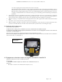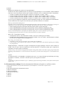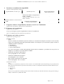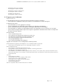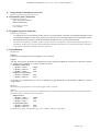
1
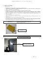
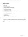
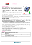
CIM2-V0-02-2007
Organisme notifié n°0071
Notified body
CERTIFICAT D'EXAMEN CE DE TYPE
EC TYPE EXAMINATION CERTIFICATE
N° LNE - 6990 rév. 0 du 15 juin 2007
Délivré par
: Laboratoire national de métrologie et d'essais
Issued by
En application
In accordance with
: Décret n°2006-447 du 12 avril 2006, et de l'arrêté du 28 avril 2006, transposant dans le droit
français la directive 2004/22/CE du 31 mars 2004 In accordance with
Décret n°2006-447 du 12 avril 2006, et de l'arrêté du 28 avril 2006, transposant dans le droit
The decree nr 2006-447 dated 12 April 2006 and the order dated 28 April 2006, transposing in the French law the council
directive 2004/22/EC of 31 Mars 2004 The decree nr 2006-447 dated 12 April 2006 and the order dated 28 April 2006,
transposing in the French law the council
Délivré à
: ASCOREL rue du Champ de Courses FRA 38780 PONT EVEQUE
Issued to
Fabricant
: ASCOREL - rue du Champ de Courses - FRA - 38780 - PONT EVEQUE
Manufacturer
Concernant
In respect of
: Un instrument de pesage à fonctionnement automatique trieur-étiqueteur type MC 402
intégré sur chargeuses à godet
An automatic catchweighing instrument type MC 402 to be incorporated in front-end loaders
Caractéristiques
Characteristics
: Classe d'exactitude : Y(b)
Classe d'environnement climatique : - 10 °C ; + 40 °C
Les autres caractéristiques figurent en annexe
Accuracy class : Y(b)
Climatic environment class : - 10 °C ; + 40 °C
Other characteristics are given in the annex
Valable jusqu'au
Valid until
: 15 juin 2017
June 15th, 2017
Les principales caractéristiques et conditions d'approbation figurent dans l'annexe ci-jointe qui fait partie intégrante du
certificat d'approbation et comprend 10 page(s). Tous les plans, schémas et notices sont déposés au Laboratoire national de
métrologie et d’essais sous la référence de dossier DDC/22/G090543
The principal characteristics, approval conditions are set out in the appendix hereto, which forms part of the approval documents and consists of 10 page(s).
All the plans, shematic diagrams and documentations are recorded by Laboratoire national de métrologie et d'essais under reference file DDC/22/G090543
Etabli le 15 juin 2007
Issued on June 15th, 2007
Pour le Directeur Général
On behalf of the General Director
Laurence DAGALLIER
Directrice Développement et Certification
Business Development and Certification
Director
ANNEXE AU CERTIFICAT (Annex to the certificate) LNE n° 6990 rev.0
Cette annexe est bilingue ; le texte original est en français. En cas de problèmes (juridiques), se référer au texte français
Aucune réclamation ou aucun droit ne peut provenir de la traduction.
This annex is bilingual ; original wording in French language. By (legal) problems refer back to the text in French language. No legal claims or
duties can be derived from the translation
Les instruments doivent correspondre aux spécifications suivantes.
The instruments shall correspond with the following specifications.
1
Désignation du type
Type designation
« MC 402 HTC » .
“MC 402 HTC” .
D’autres appellations commerciales peuvent être utilisées.
Other trading designations may be used.
2
Description
Description
2.1 Construction
Construction
L’instrument de pesage à fonctionnement automatique trieur-étiqueteur MC 402 HTC, ci-après dénommé "instrument",
est destiné à être intégré dans les chargeuses à godet. Il permet la pesée individuelle de charges de matériau pendant un
chargement.
The automatic catchweigher type MC 402 HTC - hereafter called “instrument” - is designed to be incorporated in front-end
loaders. It allows individual weighing of loads of loose material during loading.
L’opération de pesage se fait en mode dynamique ; le godet chargé est pesé lors de la levée avant sa décharge.
Toutefois, il peut également être réalisé en mode statique pour la dernière pesée composant un chargement. Le résultat
d’un chargement est la somme calculée des pesées individuelles.
The weighing function is performed in dynamic mode ; the loaded bucket is weighed during going up before it is unloaded.
However, it may also be performed in static mode for the last load to be included in a loading. The result of a loading is the
calculated sum of the individual weighings.
L'instrument est constitué par les éléments suivants.
a/ un dispositif récepteur de charge constitué par le godet.
b/ Un dispositif équilibreur et transducteur de charge constitué par deux capteurs de pression.
c/ Deux détecteurs de position définissant la fenêtre de pesage.
d/ Un détecteur de positions du godet permettant d’assurer que le déchargement du godet pesé a eu lieu avant de
commencer la pesée suivante et aussi d’assurer que le godet rechargé est en position adéquate pour être pesé.
e/ Un boîtier de raccordement pour les capteurs de pression et les détecteurs de position incluant le dispositif unité de
traitement des données analogiques ; ce boîtier est dénommé « boîtier d’acquisition » dans la suite de cette annexe.
f/ Un dispositif terminal type boîtier afficheur MC 402 HTC incluant le dispositif unité de traitement de données
numériques.
g/ Un dispositif imprimeur connecté permettant notamment d’imprimer la somme calculée des pesées individuelles
ainsi que le nombre de pesées individuelles et les valeurs des pesées individuelles.
The instrument is composed of the following parts.
a/ a load receptor composed of the bucket.
b/ A load transducer made of two pressure sensors.
c/ Two position sensors defining the weighing window.
d/ A positions sensor of the bucket allowing insurance that the unloading of the bucket has taken place before beginning the next
weighing and also allowing insurance that the re-loaded bucket is in appropriate position to be weighed .
e/ A connexion box for pressure and positions sensors including the analogic data processing unit ; this box is hereafter called
“acquisition box”.
f/ A terminal device type display panel MC 402 HTC including the digital data processing unit.
g/ One connected printer allowing in particular the printing of the calculated sum together with the number and the values of the
individual weighings.
Page 1 / 10
ANNEXE AU CERTIFICAT (Annex to the certificate) LNE n° 6990 rev.0
2.2 Capteur de mesure
Measurand sensor
Le capteur de mesure est un capteur de pression comportant les inscriptions « ASCOREL 217P00100 » et dont le type a
fait l’objet d’essais selon la recommandation R 60/2000 de l’OIML.
The measurand sensor is a pressure sensor having the inscriptions “ASCOREL 217P00100” and whose type has been tested
according to the OIML recommendation R60/2000.
2.3 Processus de pesage
Measuring process
Le conducteur de la chargeuse entre un objectif de chargement (poids cible total)
1/ Avant toute nouvelle opération de chargement, une mise à zéro est imposée au conducteur de la chargeuse qui doit
suivre les instructions affichées.
Lorsque les opérations de mise à zéro se sont correctement déroulées, le chargement peut commencer.
2/ Le conducteur de la chargeuse charge le godet en le manipulant au-dessous de la fenêtre de pesage.
Deux possibilités existent décrites aux points 2.1/ ou 2.2/ ci-après.
2.1/ Le conducteur de la chargeuse commande la montée du godet. Lorsque le premier détecteur de position de
la fenêtre de pesage est atteint, la pesée dynamique commence et se termine lorsque le second détecteur de
la fenêtre de pesage est dépassé.
Si les critères de stabilité de la mesure sont satisfaits et si la position du godet est détectée comme
satisfaisante, la pesée est validée et le godet est déchargé.
2.2/ Le conducteur de la chargeuse ajuste la charge dans le godet de manière à obtenir une charge donnée (ceci
est par exemple utilisé lors de la pesée du dernier godet qui composera le chargement).
L’obtention de la valeur souhaitée peut nécessiter une ou plusieurs pesées réalisées en mode statique (dans
le cycle automatique) de manière à ce que le conducteur de la chargeuse puisse retirer ou ajouter du
produit dans le godet jusqu’à ce que la charge soit adéquate.
Lorsque la charge est adéquate, les critères de stabilité de la mesure satisfaits et la position du godet
détectée comme satisfaisante, la pesée est validée et le godet est monté jusqu’à sa position de
déchargement puis il est déchargé.
3/ Dans les cas où les critères de stabilité de la mesure ne sont pas satisfaits ou si la position du godet est détectée
comme non satisfaisante, un messa ge visuel est affiché par l’instrument signalant que la pesée n’est pas prise en
compte et que le conducteur de la chargeuse doit redescendre le godet de manière à refaire une pesée. Cette étape
3/ est à répéter tant que la pesée n’est pas acceptée.
4/ Lorsque la pesée est acceptée, le godet est déchargé. La valeur pesée est additionnée dans la mémoire où est
totalisée la masse de produit chargée.
5/ Le conducteur de la chargeuse redescend le godet et recommence à partir de l’étape 2/.
6/ Lorsque le chargement est terminé, une impression de l’opération de chargement est commandée. Plusieurs
demandes d’impression de cette opération peuvent être commandées de manière à obtenir des duplicata du ticket
(mêmes données, mêmes références, mêmes date et heure). Il n’est plus possible d’imprimer ces données dès qu’un
nouveau chargement a commencé
The loader’s driver of the loader enters a target (total target weight)
1/ Before any other new loading sequence, a zero setting is imposed on the loader’s driver who has t o follow the instructions
displayed.
When zero setting is correctly finished, the loading sequence may begin.
2/ The loader’s driver loads the bucket working under the weighing window.
Two possibilities exist described in following paragraphs 2.1/ or 2.2/
2.1/ The loader’s driver makes the bucket go up. When the first position sensor of the weighing window is reached,
dynamic weighing begins and stops when the second detector is passed.
If the stability criteria are fulfilled and if the bucket’s position is detected as correct (from the position sensor of the
bucket), the weighing is validated and the loader’s driver can discharge the load from the bucket.
2.2/ The loader’s driver to adapt the load in the bucket in order to get a load of a hoped value (this is for example the
Page 2 / 10
ANNEXE AU CERTIFICAT (Annex to the certificate) LNE n° 6990 rev.0
3/
4/
5/
6/
case when weighing the last bucket taken into account in the total).
The operation may then include one or more weighings performed in static mode (during the automatic cycle) to
allow the loader’s driver to remove or to add product in the bucket in order to get an appropriate value of the load.
When the load is suitable and the stability criteria are satisfied and the bucket’s position detected as correct, the
weighing is validated and the drivers makes the bucket go up to its unloading position and discharges the load from
the bucket.
If the stability criteria are not fulfilled or if the bucket’s position is detected as not correct, a visual message is displayed
indicating that the this weighing is not taken into account and that the loader’s driver has to make the bucket going down in
order to perform a new weighing. This step 3/ has to be repeated as long as the weighing is not accepted.
When the weighing is accepted the load is discharged from the bucket. The weighed value is added to the memorised total
load.
The loader’s driver makes the bucket go down and starts from step 2/
When the loading is finished, a printing is ordered. Several duplicates of the ticket may be ordered (same data, same
references, same date and time) . No other ticket with these data is possible when a new loading has begun.
2.4 Indication de la valeur pesée
Measurement value indicator
L’indication de la valeur pesée est affichée sur la face avant du boîtier du module terminal.
L’écran est de type LCD (cristaux liquides) monochrome ou couleur et est accompagné d’un clavier et de touches de
commande (voir photographie 1).
Indication of the weighed value is displayed on the front of the terminal device’s front.
The screen is LCD (liquid crystal display) monochrome or colour and is accompanied with a keyboard and control commands as
illustrated hereafter (see photograph 1).
Photographie 1
Photograph 1
2.5 Équipements et fonctions soumis aux exigences de la directive 2004/22/CE
Equipments and functions subject to MID requirements
Équipements
- Le module terminal comporte des interfaces de communication (voir 4).
Equipments
- The module “terminal” has communication interfaces (see 4).
Page 3 / 10
ANNEXE AU CERTIFICAT (Annex to the certificate) LNE n° 6990 rev.0
Fonctions
Functions
-
Dispositif de chauffage du système de levage hydraulique
En fonction de la durée pendant laquelle le système de levage hydraulique est resté immobile, un déclenchement
d’une mise à zéro ou d’une pesée ne peut pas se produire sans qu’il y ait eu, en fonction de la durée d’immobilité :
* au moins 10 montées/descentes du godet si la durée est supérieure ou égale à 1 heure
* au moins 8 montées/descentes du godet si la durée est comprise entre 45 minutes inclus et 1 heure
* au moins 5 montées/descentes du godet si la durée est comprise entre 30 minutes inclus et 45 minutes
* au moins 2 montées/descentes du godet si la durée est comprise entre 15 minutes inclus et 30 minutes
Le but est que la température du fluide du système hydraulique atteigne une valeur minimale de fonctionnement.
Aucune montée/descente du godet n’est nécessaire pour une durée inférieure à 15 minutes.
Warm-up of the hydraulic lifting device
depending on the period of time during which the hydraulic lifting device has been motionless, a release of a zero setting or a
weighing can’t occur unless there has been, d epending of the period of time the device has been motionless :
* at least 10 lifting/going down of the bucket when the period is equal or greater than 1 hour
* at least 8 lifting/going down of the bucket when the period is between 45 minutes included and 1 hour
* at least 5 lifting/going down of the bucket when the period is between 30 minutes included and 45 minutes
* at least 2 lifting/going down of the bucket when the period is between 15 minutes included and 30 minutes.
The aim is that the temperature of the fluid of the hydraulic lifting device reaches a minimum operating value.
No lifting/going down of the bucket is necessary when the period is lower than 15 minutes.
-
Mise à zéro ; l’instrument est équipé :
* d’un dispositif de mise à zéro initial dont l’étendue est de 20 % de Max (peut être inhibé)
* d’un dispositif semi-automatique de mise à zéro dont l’étendue est de 4 % de Max ; opération imposée au départ
de tout nouveau chargement (voir paragraphe 2.3)
Zero setting ; the instrument has :
* an initial zero setting, the range of which is 20 % of Max (may be inhibited)
* a semi -automatic zero setting, the range of which is 4 % of Max ; this function is forced at the beginning of new loading
(see paragraph 2.3).
-
Réglage dynamique : l’instrument est équipé d’un dispositif de réglage dynamique valide sur toute l’étendue de
pesage et mis en œuvre selon les instructions écrites du fabricant. Ce dispositif, protégé par le dispositif de
scellement, est non accessible à l’utilisateur.
Dynamic setting : the in strument is equipped with a dynamic setting facility valid over the whole weighing range and operated
according to the manufacturer’s written instructions. This facility, protected by the sealing device, is not available to the
user.
-
Logiciel
Au regard du guide 7.2 de WELMEC, l’instrument est de type « P » (conçu et fabriqué spécialement pour l’usage
décrit dans ce certificat) ; aucune des extensions prévues par le guide n’est utilisée.
-
Software
From Welmec 7.2 guide, the instrument is type “P” (Built-for-purpose measuring instrument) ; none of the extensions of the
guide is used.
2.6 Documentation technique (Liste des documents du fabricant sur lesquels ce certificat est basé)
Technical documentation (List of technical documents of the manufacturer on which this certificate bases)
1
2
3
4
5
6
7
8
Demande
Description générale de l’instrument de mesure
Plans de conception
Plans de Fabrication
Procédés de fabrication
Logiciel
Manuels
Normes
Page 4 / 10
ANNEXE AU CERTIFICAT (Annex to the certificate) LNE n° 6990 rev.0
9 Scellements et marquages
1 Application
2 General description of the measuring instrument
3 Designing drawings
4 Manufacturing drawings
5 Manufacturing processes
6 Software
7 Manuals
8 Standards
9 Sealings and markings
2.7 Équipements intégrés et fonctions non soumis à MID
Integrated equipment and functions not subject to MID
D’autres équipements ou fonctions non concernés par la directive peuvent être adjoints à l’instrument.
Other equipments or functions not subject to MID may be attached to the instrument.
3
Caractéristiques
Technical data
3.1 Conditions assignées de fonctionnement
Rated operating conditions
* Classe d’exactitude (accuracy class)
* Classe d’environnement climatique
(Climatic influence class)
* Classe d’environnement mécanique
(Mechanical influence class)
* Classe d’environnement électromagnétique
(Electromagnetic influence class)
* Portée maximale (maximum capacity)
* Échelon (scale division)
* Nombre d’échelons (Number of verification scale intervals)
* Portée minimale (minimum capacity)
Y(b)
-10 °C, + 40°C
Non applicable aux IPFA
Not applicable to AWIs
E3
Max ≥ 2 t
e ≥ 20 kg
100 ≤ n ≤ 300
10 e
3.2 Autres conditions de fonctionnement
Other operating conditions
-
-
-
La prise en compte d’une pesée ou d’une opération de mise à zéro ne sont possibles que lorsque le godet est levé
complètement verticalement et lorsque la position de pesée (cas d’une pesée en mode statique) ou la fenêtre de
pesage (cas d’une pesée en mode dynamique) sont atteintes depuis la position basse du godet. En outre, en mode
dynamique, le godet doit être levé de manière constante depuis le détecteur de position inférieur au détecteur de
position supérieur de la fenêtre de pesage.
Au début d’un nouveau chargement, la mémoire de stockage des valeurs à imprimer est réinitialisée.
Validation of a weighed value or a zero setting only possible when the bucket is completely lifted upright and when the
weighing position (in case of static weighing) or the weighing window (in case of dynamic weighing) are accessed from the
lower position of the bucket. In addition, for dynamic weighing, the bucket has to be lifted constantly from the lower position
sensor to the upper position sensor of the weighing window.
At the beginning of a new loading, the device for storing the values to print is reset.
Page 5 / 10
ANNEXE AU CERTIFICAT (Annex to the certificate) LNE n° 6990 rev.0
4
Interfaces et conditions de compatibilité
Interfaces and compatibility conditions
Fonction (function)
Type d’interface (interface type)
Autre(s) information(s)
(Other information(s))
Interfaces internes (internal interfaces)
Connexion du boîtier d’acquisition au
module « terminal »
Connexion of the acquisition box to the
module “terminal”
Interfaces externes (external interfaces)
USB
Série RS 232
5
Connexions de périphériques
Connexions of peripherals
-
-
Exigences relatives à la production, à la mise en service et à l’utilisation
Requirements on production, putting into use and utilization
5.1 Exigences sur la production
Requirements on production
Il n’y a pas d’exigence spéciale supplémentaire relative à la production.
There is no additional special requirement on production.
5.2 Exigences sur la mise en service
Requirements on putting into use
Examens et essais
- Essais
Outre les examens de conformité au présent certificat, les essais doivent comporter au moins les essais suivants,
réalisés sur l’instrument entièrement opérationnel installé sur la chargeuse qu’il est destiné à équiper et dans les
conditions normales d’utilisation.
• Excentration
• Essai de pesage
• Essai de dénivellement
Ces essais sont réalisés en mode fonctionnement normal selon les méthodes et procédures d’essai prévues au
chapitre 6 et à l’Annexe A de la R51/2006 de l’OIML.
-
Examen des inscriptions réglementaires
Voir le paragraphe 8.1 de ce certificat
-
Examen de l’identification du logiciel
Voir paragraphe 7 de ce certificat
-
Mise en place du dispositif de scellement
Selon le paragraphe 7 de ce certificat
Examinations and tests
- Tests
In addition to examination of conformity to this certificate, tests shall include at least the following tests performed on the
fully operational instrument incorporated on the loader for which it is manufactured and in the normal conditions of use.
• Eccentricity
• Weighing test
• Tilting
These tests are performed in normal operation mode with the test loads for which the instrument is designed according to
Chapter 6 and Annex A of OIML R51/2006.
Page 6 / 10
ANNEXE AU CERTIFICAT (Annex to the certificate) LNE n° 6990 rev.0
-
Examination of descriptive markings
See paragraph 8.1 of this certificate
-
Examination of software identification
See paragraph 7 of this certificate
-
Installation of sealing device
See paragraph 7 of this certificate
5.3 Exigences pour l’utilisation
Requirements for use
La documentation fournie par le fabricant (manuel d’utilisation) comporte notamment :
- la description des commandes à entrer pour accéder à la visualisation des versions de logiciel
L’utilisateur doit assurer :
- que l’instrument est et reste approprié à son usage
- que les performances de l’instrument restent conformes aux tolérances réglementaires
- que les scellements ainsi que les inscriptions et marquages réglementaires restent intègres
- que l’instrument est conforme à la réglementation relative aux instruments en service du pays où il est utilisé
- que les formats d’étiquette définis respectent les exigences réglementaires notamment celles relatives à l’impression
des unités de mesure utilisées.
Une intervention :
- sur les vérins de levage et/ou
- sur les détecteurs de position de la fenêtre de pesage et/ou
- sur le détecteur de positions du récepteur de charge et/ou
- sur le moteur (puissance, nombre de tours/min) et/ou
- sur la pompe hydraulique et/ou
- sur le système anti-tangage de la chargeuse
engendre une vérification. Ceci est indiqué dans le manuel opérateur.
The documentation supplied by the manufacturer (user’s manual) includes in particular :
the description of commands to get access to the display of software versions
The user shall insure that :
the instrument is and remains appropriate for its use
the performances of the instrument remain in conformity with the legal tolerances
the sealing device and markings remain safe
the instrument is in accordance with the regulation about control in service of the country where the instrument is used
the formats of the labels are in accordance with the legal requirements, especially these related to the printing of units of
measurement used.
An action :
on the lifting levers and/or
on the position sensors of the weighing window and/or
on the positions sensor of the bucket and/or
on the engine (power, number of cycles/min) and/or
on the hydraulic pump and/or
on the anti-pitching device,
leads to a verification. This is mentioned in the user’s manual.
Page 7 / 10
ANNEXE AU CERTIFICAT (Annex to the certificate) LNE n° 6990 rev.0
6
Inspection des instruments en service
Inspection of measuring instruments in use
6.1 Documents pour l’inspection
Documents for inspection
-
Copie du présent certificat
Manuel d’utilisation
-
Copy of this certificate
User’s manual
-
6.2 Équipement pour l’inspection
Equipment for inspection
-
-
Les charges d’essai sont constitués par des masses et/ou poids étalons conformes à la législation nationale et dont
l’utilisation ne conduit pas à une erreur supérieure au tiers de l’erreur maximale tolérée sur l’instrument à vérifier.
Un inclinomètre doit permettre l’évaluation du dénivellement lors des essais de dénivellement
Test loads are composed of standard weights or masses which are in conformity with national legislation and the use of
which doesn’t lead to an error greater than one third of the maximum permissible error of the instrument under verification.
A tilt indicator shall allow evaluation of tilt for the tilt test.
6.3 Identification
Identification
Matériel
L’instrument est désigné selon le paragraphe 1 de ce certificat.
Logiciel
A la mise sous tension, un contrôle de l’intégrité des parties de logiciel implantées est réalisé par calculs des sommes
de contrôle correspondantes. Les valeurs sont les suivantes.
- BOÎTIER AFFICHEUR
* Module « TDB » :
72DB
* Module « BOOT » :
38CC
* Module « USB » :
0190
- BOÎTIER ACQUISITION
* Module « NOEUD » : 6F20
* Module « BOOT » :
5AC3
On accède à la visualisation de ces valeurs en partant de la page principale, en sélectionnant « MENU » et ensuite
« Page TEST ».
Hardware
The instrument is designated as written in paragraph 1 of this certificate.
Software
After switch-on, the integrity of the parts of embedded software is checked through calculation of the corresponding checksums.
The values of these checksums are given hereafter.
-
-
DISPLAY BOX
* Module « TDB » :
* Module « BOOT » :
* Module « USB » :
ACQUISITION BOX
* Module « NOEUD » :
* Module « BOOT » :
72DB
38CC
0190
6F20
5AC3
To display these values, from the main page, select “MENU” and then “ Page TEST”
Page 8 / 10
ANNEXE AU CERTIFICAT (Annex to the certificate) LNE n° 6990 rev.0
7
Mesures de sécurité
Security measures
-
-
Scellement au niveau du boîtier d’acquisition (voir illustration n°1)
Scellement au niveau du boîtier du module terminal pour éviter l’accès au cavalier empêchant les modifications des
réglages et paramètres (voir illustration n°2)
Reconnaissance croisée du boîtier d’acquisition et du boîtier du module terminal :
le boîtier d’acquisition et le boîtier du module terminal sont liés par une reconnaissance croisée empêchant
notamment la connexion d’un autre boîtier terminal. Ceci rend le scellement de la connexion entre les 2 boîtiers
inutile. La reconnaissance croisée est le numéro de série du Boîtier Afficheur, visible dans la page TEST avec les
valeurs de contrôle.
Sealing of the acquisition box (see illustration n°1)
Sealing of the terminal box to avoid access to the strap which prevents against changes of settings and parameters (see
illustration n°2)
Cross reference between the acquisition box and the terminal box :
the acquisition box and the terminal box are bound by a cross reference which prevents in particular connection of another
terminal box. This makes a sealing of the connection between the 2 boxes unnecessary. The cross -reference is the serial
number of the Display Box, and it is displayed in the TEST page with the values of the checksums.
Illustration n°1 –
Scellement au niveau du boîtier de connexion
Sealing of the acquisition box
Etiquette de scellement
Sealing sticker
Illustration n°2
Vue latérale du boîtier terminal
Etiquettes de scellement
Une sur chaque face latérale
Page 9 / 10
ANNEXE AU CERTIFICAT (Annex to the certificate) LNE n° 6990 rev.0
8
Marquage et inscriptions
Labelling and inscriptions
8.1 Inscriptions réglementaires
Descriptive markings
Les inscriptions réglementaires sont :
- nom ou marque d'identification du fabricant
- numéro de série et désignation du type de l'instrument
- tension de l'alimentation électrique, en V
- numéro du présent certificat
- classe d'exactitude sous la forme Y(b)
- échelon de vérification et échelon sous la forme « e = d = … »
- portée maximale sous la forme « Max = … »
- portée minimale sous la forme « Min = … »
Ces inscriptions figurent sur une étiquette destructible par arrachement située sur la face arrière du boîtier terminal.
The descriptive markings are :
- name or identification mark of the manufacturer
- serial number and type designation of the instrument
- power supply voltage in V
- number of this certificate
- accuracy class in the form Y(b)
- verification scale interval and scale interval in the form : “e = d = …”
- maximum capacity in the form : “Max = …”
- minimum capacity in the form : “Min = …”
These markings are on a sticker not removable without being destroyed located on the back side of the terminal box.
8.2 Marquage de conformité
Le marquage prévu aux paragraphes 1, 2, 3 et 5 de l’article 19 de la directive 2004/22/CE figure dans le voisinage des
inscriptions réglementaires.
The markings meant in paragraphs 1, 2, 3 and 5 of article 19 of directive 2004/22/EC are in the vicinity of the descriptive
markings.
Page 10 / 10