1
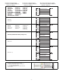
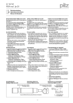
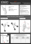
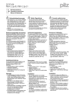
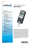
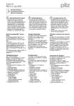
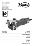
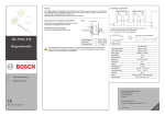
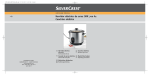
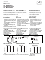
20 934-05
PSEN 1.1p-10
4
4
4
D
Betriebsanleitung
GB Operating instructions
F
Manuel d'utilisation
20 934-05
PSEN
1.1p-10
Sicherheitsschalter PSEN 1.1p-10
Safety switch PSEN 1.1p-10
Capteur de sécurité PSEN 1.1p-10
Der Sicherheitsschalter erfüllt Forderungen der
EN 60204-1 und IEC 60204-1.
Der Sicherheitsschalter erfüllt EN 60947-5-3
nur zusammen mit dem Betätiger PSEN 1.1-10
und hierfür zugelassenen Auswertegeräten.
Schließen Sie den Sicherheitsschalter nur an
Auswertegeräte an, die im Abschnitt "Anschlüsse" aufgeführt sind.
The safety switch meets the requirements of
EN 60204-1 and IEC 60204-1.
The safety switch only complies with
EN 60947-5-3 in conjunction with the actuator
PSEN 1.1-10 and its approved evaluation devices.
The safety switch should only be connected to
the evaluation devices listed under "Connections".
Le capteur de sécurité satisfait aux exigences
de l'EN 60204-1 et de la CEI 60204-1.
Le capteur de sécurité ne répond à la norme
EN 60947-5-3 que s'il est utilisé avec l'organe
de commande PSEN 1.1-10 et les appareils de
contrôle spécialement homologués.
Raccordez les capteurs de sécurité uniquement aux appareils de contrôle énumérés au
chapitre "Raccordements".
Zu ihrer Sicherheit
` Installieren und nehmen Sie das Gerät nur
For your safety
` Only install and commission the unit if you
Pour votre sécurité
` Vous n'installerez l'appareil et ne le mettrez
dann in Betrieb, wenn Sie diese Betriebsanhave read and understood these operating
en service qu'après avoir lu et compris le
leitung gelesen und verstanden haben und
instructions and are familiar with the applica- présent manuel d'utilisation et vous être faSie mit den geltenden Vorschriften über Arble regulations for health and safety at work
miliarisé avec les prescriptions en vigueur
beitssicherheit und Unfallverhütung vertraut
and accident prevention.
sur la sécurité du travail et la prévention des
sind.
Ensure VDE and local regulations are met,
accidents.
Beachten Sie die VDE- sowie die örtlichen
especially those relating to safety.
Respectez les normes locales ou VDE, parti` Any guarantee is rendered invalid if the hous- culièrement en ce qui concerne la sécurité.
Vorschriften, insbesondere hinsichtlich
ing is opened or unauthorised modifications ` L'ouverture de l'appareil ou sa modification
Schutzmaßnahmen
` Durch Öffnen des Gehäuses oder eigenannule automatiquement la garantie.
are carried out.
` Do not remove the protective cap until you ` Veuillez retirer le cache de protection avant
mächtige Umbauten erlischt jegliche Geare just about to connect the unit.
de raccorder l'appareil.
währleistung.
` Entfernen Sie die Schutzkappe erst unmittelbar vor Anschluss des Geräts.
Gerätemerkmale
Unit features
` Zum Sicherheitsschalter gehört der Betätiger ` The actuator PSEN 1.1-10 belongs to the
`
`
`
`
`
`
PSEN 1.1-10
2 Reedkontakte (Schließer)
gesicherter Schaltabstand: 3 mm
gesicherter Ausschaltabstand: 19 mm
eckige Bauform
Wirkweise magnetisch
Schaltspannung 24 V DC
Schaltabstände
`
`
`
`
`
`
safety switch
2 reed contacts (N/O)
Assured operating distance: 3 mm
Assured release distance: 19 mm
Square design
Works magnetically
Switching voltage 24 VDC
`
`
`
`
`
`
Operating distances
Seitenversatz/Lateral offset/
Décalage latéral
Caractéristiques de l'appareil
` Un organe de commande est associé au
capteur de sécurité PSEN 1.1-10
2 contacts Reed (contacts à fermeture)
distance de commutation de sécurité : 3 mm
distance de coupure de sécurité : 19 mm
architecture rectangulaire
actionnement magnétique
tension commutée 24 V DC
Distances de commutation
Höhenversatz/Height offset/ Schaltabstand/Operating distance/
Portee de travail
Décalage en hauteur
aktive Fläche
active area
surface active
sar = 19
sao = 3
somin = 0,5
Ein/On/Marche
Aus/Off/Arrêt
Höhenversatz/Height offset/
Décalage en hauteur
Höhenversatz/Height offset/
Décalage en hauteur
1,5
2,0
2,5
3,0
1,0
2,5
2,5
2,0
1,5
1,5
1,5
2,0
2,0
2,0
1,0
1,0
2,0
2,0
1,5
1,5
1,0
0,5
2,5
1,5
1,0
0,5
-
-
3,0
0,5
0,5
-
-
-
mm
1,0
1,5
2,0
2,5
3,0
1,0
2,5
2,5
2,0
1,5
1,5
1,5
2,0
2,0
2,0
1,0
1,0
2,0
2,0
1,5
1,5
1,0
0,5
2,5
1,5
1,0
0,5
-
-
3,0
0,5
0,5
-
-
-
` Gesicherter Ausschaltabstand Sar:
Décalage latéral et en hauteur
` Distance de commutation de sécurité Sao en
Höhenversatz/Height offset/
Décalage en hauteur
Seitenversatz/Lateral
offset/Décalage latéral
1,0
Seitenversatz/Lateral
offset/Décalage latéral
Lateral and vertical offset
` Assured operating distance Sao in mm
Seitenversatz/Lateral
offset/Décalage latéral
Seiten- und Höhenversatz
` Gesicherter Schaltabstand Sao in mm
1,0
1,5
2,0
2,5
3,0
1,0
2,5
2,5
2,0
1,5
1,5
1,5
2,0
2,0
2,0
1,0
1,0
2,0
2,0
1,5
1,5
1,0
0,5
2,5
1,5
1,0
0,5
-
-
3,0
0,5
0,5
-
-
-
` Assured release distance Sar:
Max. 19 mm bei allen Höhen- und Seitenver- Max. 19 mm with all vertical and lateral off- ` Distance de commutation de sécurité Sar :
sätzen
sets
Max. 19 mm pour tous les décalages latéDie angegebenen Werte sind gültig bei einer
The stated values are valid at a temperature of
raux et en hauteur
Temperatur von 20° C.
20° C.
Les valeurs indiquées sont valables pour une
température de 20°C.
-1-
Verdrahtung
Wiring
Câblage
Beachten Sie:
Please note:
Important :
` Angaben im Abschnitt „Technische Daten“ ` Information given in the “Technical details” ` Tenez compte impérativement des données
unbedingt einhalten.
must be followed.
indiquées au chapitre "Caractéristiques
` Berechnung der max. Leitungslänge Imax im ` Calculation of the max. cable runs lmax in the techniques".
` Calcul de la longueur de câble max. Imax sur
Eingangskreis:
input circuit:
le circuit d'entrée :
Rlmax
Rlmax
Imax =
Imax =
Rlmax
Rl / km
Rl / km
Imax =
Rl / km
Rlmax = max. Gesamtleitungswiderstand
Rlmax = max. overall cable resistance (see
Rlmax = résistance max. de l'ensemble du
(s. techn. Daten)
Technical details)
câblage (voir les caractéristiques techniRl / km = Leitungswiderstand/km
Rl / km = cable resistance/km
ques)
` Beachten Sie bei Einsatz von Auswertegerä- ` When using evaluation devices with delay-on
Rl /km = résistance du câblage/km
ten mit rückfallverzögerten Kontakten:
de-energisation contacts, please note:
– Verzögerungszeit ≤ 30 s: die rückfallverzö- – Delay time ≤ 30 s: Delay-on de-energisa- ` En cas de mise en œuvre d'appareils de congerten Kontakte genügen den Anforderuntion contacts satisfy the requirements of
trôle avec contacts temporisés à la retomgen der Kategorie 3 gemäß EN 954-1 bzw.
category 3 in accordance with EN 954-1
bée, il faut tenir compte des indications
den Anforderungen an PDF mit Einfehlersiand the requirements of a PDF with single- suivantes :
cherheit (PDF-S).
fault tolerance (PDF-S).
– Temporisation ≤ 30 s : les contacts tempo– Verzögerungszeit ≥ 30 s: die rückfallverzö- – Delay time ≥ 30 s: Delay-on de-energisarisés à la retombée satisfont aux prescripgerten Kontakte genügen den Anforderuntion contacts satisfy the requirements of
tions de la catégorie 3 selon l'EN 954-1, et/
gen der Kategorie 1 gemäß EN 954-1 bzw.
Category 1 in accordance with EN 954-1
ou aux prescriptions des PDF avec sécuriden Anforderungen an PDF mit Zuverläsand the requirements of a PDF with deté de défaut unique (PDF-S).
sigkeit durch besonderes Design (PDF-D).
signed reliability (PDF-D).
– Temporisation ≥ 30 s : les contacts tempo` Überprüfen Sie in folgenden Fällen von Inbe- ` In the following commissioning cases, check
risés à la retombée satisfont aux prescriptriebnahme die Funktion Querschlusserkenthe function that detects shorts across contions de la catégorie 1 selon l'EN 954-1, et/
nung:
tacts:
ou aux prescriptions des PDF avec une
– Bei Auswertegeräten mit Versorgungs– On evaluation devices with DC supply
fiabilité obtenue grâce à un design particuspannung DC: Gesamtleitungswiderstand
voltage: Overall cable resistance ≥ 15
lier (PDF-D).
≥ 15 Ohm pro Kanal
Ohms per channel
` Vérifiez dans les cas suivants de mise en ser– Bei Auswertegeräten mit Versorgungs– On evaluation devices with AC supply volt- vice la fonction de détection des courtsspannung AC: Gesamtleitungswiderstand
age: Overall cable resistance ≥ 25 Ohms
circuits :
≥ 25 Ohm pro Kanal
per channel
– pour les appareils de contrôle avec ali– Wie Sie die Querschlussprüfung durchfüh- – For details of how to perform the test for
mentation DC : Résistance de l'ensemble
ren müssen, entnehmen Sie der entspreshorts across the contacts, please refer to
du câblage ≥ 15 ohms par canal
chenden Bedienungsanleitung des
the operating manual for the relevant eval- – pour les appareils de contrôle avec aliAuswertegeräts.
uation device.
mentation AC : Résistance de l'ensemble
du câblage ≥ 25 ohms par canal
– vous trouverez dans la notice d'utilisation
de l'appareil de contrôle comment exécuter le contrôle des courts-circuits.
Anschlüsse
Connections
Raccordements
WICHTIG
NOTICE
IMPORTANT
Die Farbkennzeichnung für die AnschlussThe colour marking for the connection lead
Le codage de couleur du câble de raccorleitung gilt nur für die als Zubehör erhältlionly applies for the cable that Pilz supplies
dement est valide uniquement pour les câchen Kabel von Pilz.
as an accessory.
bles Pilz disponibles comme accessoires.
Der Sicherheitsschalter ist in unbetätigtem Zu- The safety switch is shown in an unoperated Le capteur de sécurité est représenté en posistand dargestellt.
condition.
tion de repos.
Belegung des 4-pol. M8-Stiftsteckers/Assignment of the 4-pin M8 male connector/Repérage du connecteur mâle M8 à 4 pôles
1
2
3
4
1
2
3
-2-
4
Anschluss an Auswertegeräte
` Anschluss an PNOZ X, PNOZpower,
PNOZsigma, PNOZelog
PNOZ p1p
PNOZ p1vp
PNOZ X2/X2P
PNOZ X2.1
(nur 24 V DC/
24 V DC only/
24 V DC seulement)
PNOZ X2.3P
PNOZ X2.7P
PNOZ X2.8P/X2.9P
PNOZ X2C
PNOZ X2.1C
(nur 24 V DC/
24 V DC only/
24 V DC seulement)
PNOZ X4/X8P
PNOZ X9/X9P
PNOZ X10/X10.1
PNOZ X10.11P
PNOZ Ex
Connection to evaluation devices
` Connection to PNOZ X, PNOZpower,
PNOZsigma, PNOZelog
PNOZ e1p
PNOZ e1.1p
PNOZ e1vp
PNOZ e6.1p
PNOZ e6vp
PNOZ s3
PNOZ s4
PNOZ s5
Raccordement aux unités de contrôle
` Raccordement au PNOZ X, PNOZpower,
PNOZsigma, PNOZelog
S21
S22
S11
S12
S11
S22
PNOZ X5
PNOZ X5J
S11
S12
PNOZ 11
PNOZ 16
PNOZ X11P
PNOZ X13
PNOZ X3.1
PNOZ X3P
PNOZ X2.5P
PNOZ X3
S21
PNOZ X3.10P
PNOZ XV2
PNOZ XV2P
PNOZ XV3
PNOZ XV3P
S22
S31
S32
S23
S24
PNOZ X6 (mit Brücke/with link/avec pontage Y3-Y4)
S11
S12
S61
S62
PMUT X1P
S51
S52
A1
S22
A1
S12
PNOZ e5.11p
A1
S42
A1
S32
` Anschluss an PNOZmulti
` Connection to PNOZmulti
Schutztür/saftey gate/protecteur mobile
Schaltertyp 3/switchtype 3/type du capteure 2
I0, I1: Eingänge/inputs/entrées
T0, T1: Taktausgänge/test pulse outputs/sorties
impulsionelles
braun/brown/marron
weiß/white/blanc
blau/blue/bleu
schwarz/black/noir
braun/brown/marron
weiß/white/blanc
blau/blue/bleu
schwarz/black/noir
braun/brown/marron
weiß/white/blanc
blau/blue/bleu
schwarz/black/noir
braun/brown/marron
weiß/white/blanc
blau/blue/bleu
schwarz/black/noir
braun/brown/marron
weiß/white/blanc
blau/blue/bleu
schwarz/black/noir
braun/brown/marron
weiß/white/blanc
blau/blue/bleu
schwarz/black/noir
braun/brown/marron
weiß/white/blanc
blau/blue/bleu
schwarz/black/noir
2
3
4
1
2
3
4
1
2
3
4
1
2
3
4
1
2
3
4
1
2
3
4
1
2
3
4
` Raccordement au PNOZmulti
T0
I0
T1
I1
-3-
1
braun/brown/marron
weiß/white/blanc
blau/blue/bleu
schwarz/black/noir
1
2
3
4
` Anschluss an PSS mit oder ohne
` Connection to PSS with or without
SafetyBUS p
SafetyBUS p
O 16
Schutztür/saftey gate/protecteur mobile
Schaltertyp 3/switchtype 3/type du capteure 2
I0, I1: Eingänge/inputs/entrées
O16, O17: Taktausgänge/test pulse outputs/sorties
impulsionelles
Montage
` Die Montagelage ist beliebig. Sicherheits`
`
`
`
`
schalter und Betätiger müssen jedoch parallel gegenüberliegend montiert werden.
Sicherheitsschalter und Betätiger möglichst
nicht auf ferromagnetisches Material montieren. Es sind Änderungen der Schaltabstände
zu erwarten. Benutzen Sie in diesem Fall die
Distanzplatte mit der Bestell-Nr. 534 310.
Befestigen Sie Sicherheitsschalter und Betätiger ausschließlich mit Schrauben M4 mit
flacher Kopfunterseite (z.B. M4-Zylinderkopf- oder -Flachkopfschrauben). Anzugsdrehmoment max. 1 Nm. Verwenden Sie
Schrauben aus nicht magnetischem Material
(z. B. Messing).
Der Abstand zwischen zwei Systemen aus
Sicherheitschalter und Betätiger muss mindestens 25 mm betragen.
Sicherheitsschalter und Betätiger
– von Eisenspänen fernhalten
– keinen starken Magnetfeldern aussetzen
– keinen starken Stößen oder Schwingungen aussetzen
– nicht als Anschlag benutzen
Die Schutzart IP67 wird nur bei Verwendung
der als Zubehör erhältlichen Anschlussleitungen von Pilz erreicht. Ansonsten wird nur
IP65 erreicht.
` Raccordement au PSS avec ou sans
SafetyBUS p
I 00
O 17
I 01
Installation
` The unit can be installed in any position.
`
`
`
`
`
However, safety switches and actuators
must be positioned opposite each other in
parallel:
If possible, do not install the safety switch
and actuator on to ferromagnetic material.
Changes to the operating distances are to be
expected. In this case, use the spacer available under order number 534 310.
Safety switches and actuators should only
be secured using M4 screws with a flat head
(e.g. M4 cheese-head or pan head screws).
Torque setting max. 1 Nm. Use screws made
of non-magnetic material (e.g. Messing).
The distance between two systems comprising safety switch and actuator must be at
least 25 mm.
Safety switch and actuator
– Keep away from iron swarf
– Do not expose to strong magnetic fields
– Do not expose to heavy shock or vibration
– Do not use as a limit stop
Protection type IP67 can only be achieved by
using the Pilz connection leads available as
an accessory. In any other case only IP65 is
achieved.
braun/brown/marron
weiß/white/blanc
blau/blue/bleu
schwarz/black/noir
1
2
3
4
Installation
` Le sens de montage est indifférent. Cepen-
`
`
`
`
`
dant, le capteur de sécurité et l'organe de
commande doivent être montés l'un en face
de l'autre de manière parallèle.
Evitez d'installer le capteur de sécurité et
l'organe de commande sur du matériel ferromagnétique. Les distances de commutation
peuvent être modifiées. Utilisez dans ce cas
le support séparateur portant la référence
534 310.
Pour fixer le capteur de sécurité et l'organe
de commande, utilisez uniquement des vis
M4 dont la tête présente une face inférieure
plate (par ex. une vis M4 cylindrique ou à tête
plate). Couple de serrage maxi 1 Nm. Utilisez
des vis en métal non magnétique (par ex. en
laiton).
La distance minimale entre deux systèmes
de capteur de sécurité et d'organe de commande doit être d'au moins 25 mm.
Le capteur de sécurité et l'organe de commande
– doivent être éloignés des copeaux métalliques
– ne doivent pas être exposés à des champs
magnétiques élevés
– ne doivent pas subir des chocs et vibrations importants
– ne doivent pas être utilisés comme butée
L'indice de protection IP67 est uniquement
atteint lorsque les câbles de raccordement
de Pilz, disponibles dans les accessoires,
sont utilisés, sans quoi, seul l'indice IP65
peut être atteint.
Justage
Adjustment
Ajustement
` Der Sicherheitsschalter darf nur mit dem zu- ` The safety switch may only be used with the ` Le capteur de sécurité ne doit être utilisé
gehörigen Betätiger PSEN 1.1-10 verwendet
corresponding actuator PSEN 1.1-10.
qu'avec un organe de commande PSEN 1.1werden.
10 adapté.
` Always test the function with one of the ap` Prüfen Sie die Funktion immer mit einem der proved evaluation devices.
` Vérifiez la fonction toujours avec l'un des apzugelassenen Auswertegeräte.
` The stated operating distances (see Techni- pareils de contrôle homologués.
` Die angegebenen Schaltabstände (siehe
cal details) only apply when the safety switch ` Les distances de commutation mentionnées
technische Daten) gelten nur, wenn Sicherdans les caractéristiques techniques sont
and actuator are installed facing each other
heitsschalter und Betätiger parallel gegenvalables uniquement lorsque le capteur de
in parallel. Switching distances may deviate
überliegend montiert sind. Andere
sécurité et l'organe de commande sont monif other arrangements are used. Note the
Anordnungen können zu abweichenden
tés l'un en face de l'autre de manière parallèmaximum permitted lateral and vertical offSchaltabständen führen. Beachten Sie den
set (see "Operating distances" and "Max. lat- le. D'autres montages peuvent conduire à
maximal zulässigen Seiten- und Höhenverdes distances de commutation divergentes.
eral and vertical offset").
satz (siehe "Schaltabstände" und "Max. SeiRespectez le décalage latéral et vertical
ten- und Höhenversatz").
maximal autorisé (voir "Distances de commutation" et "Décalage latéral et vertical
maximum").
-4-
Abmessungen
Dimensions
Dimensions
Safety switch
13
36
22
5
8,
6,5
6,8
4,5
19
26
10,6
M8x1
Actuator
19
26
4,5
5
8,
22
13
36
Technische Daten
Technical details
Caractéristiques techniques
Zulassungen
Schaltabstände
Gesicherter Schaltabstand Sao
Min. Schaltabstand Somin
Gesicherter Ausschaltabstand Sar
Approvals
Switching distances
Assured operating distance Sao
Min. operating distance Somin
Assured release distance Sar
Homologations
Distances de commutation
Portée de travail assurée Sao
Portée de travail min. Somin
Portée de déclenchement assurée
Sar
Tension de commutation
Courant max. de commutation des
contacts Reed
Puissance max. de commutation
des contacts Reed
Fréquence de commutation max.
Actionneur
Température d'utilisation
Vibrations selon EN 60947-5-2
Fréquence
Amplitude
Résistance aux chocs
Type de connection
Câble
Indice de protection
Matériau du boîtier
Dimensions
Capteur de sécurité
Hauteur
Largeur
Profondeur
Actionneur
Hauteur
Largeur
Profondeur
Poids
Capteur de sécurité
Actionneur
Schaltspannung
Max. Schaltstrom Reedkontakte
Switching voltage
Max. switching current for reed
contacts
Max. Schaltleistung Reedkontakte Max. breaking capacity for reed
contacts
Max. Schaltfrequenz
Max. switch frequency
Betätiger
Actuator
Umgebungstemperatur
Ambient temperature
Schwingungen nach EN 60947-5-2 Vibration to EN 60947-5-2
Frequenz
Frequency
Amplitude
Amplitude
Schockbeanspruchung
Shock stress
Anschlussart
Connection type
Leitung
Cable
Schutzart
Protection type
Gehäusematerial
Housing material
Abmessungen
Dimensions
Sicherheitsschalter
Safety switch
Höhe
Height
Breite
Width
Tiefe
Depth
Betätiger
Actuator
Höhe
Height
Breite
Width
Tiefe
Depth
Gewicht
Weight
Sicherheitsschalter
Safety switch
Betätiger
Actuator
Es gelten die 2006-12 aktuellen Ausgaben der The standards current on 2006-12 apply.
Normen.
20934-05
-5-
BG, CE, UL/cUL
3 mm
0,5 mm
19 mm
24 V
0,50 A
10,0 W
1 Hz
PSEN 1.1-10
-10 - 55 °C
10 - 55 Hz
1,00 mm
30 g , 11 ms
M8
LiYY 4 x 0,25 mm2
IP65/IP67
PBT
43,0 mm
26,0 mm
13,0 mm
36 mm
26 mm
13 mm
14 g
15 g
Les versions actuelles 2006-12 des normes
s'appliquent.
20934-05, 2007-03 Printed in Germany