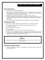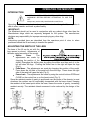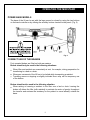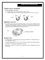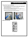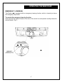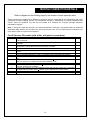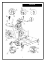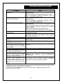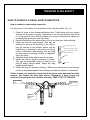
1
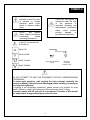
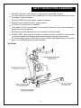
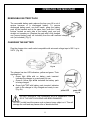
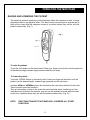
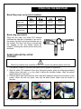
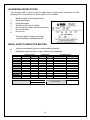
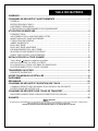
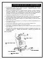
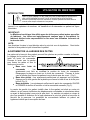
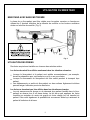
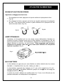
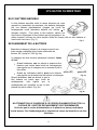
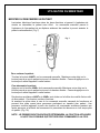
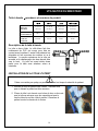
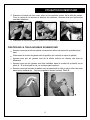
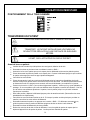
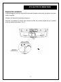
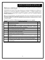
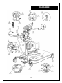
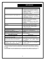
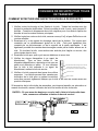
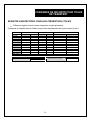
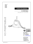
MODELS
865XXXXX
866XXXXX
OPERATING MANUAL
MINISTAND
STAND UP LIFT
Fig.9
17
2001, Tanguay Street
Magog (Québec)
Canada
J1X 5Y5
Tel.:
(819) 868-0441
Toll Free 1-800-868-0441
Fax : (819) 868-2249
www.bhm-medical.com
mars 2005_rev4
#001.20075
2
TABLE OF CONTENTS
SYMBOLS .................................................................................................................................. 4
SAFETY INSTRUCTIONS & WARNINGS ................................................................................. 5
GENERAL ............................................................................................................................................... 5
SHOCK PREVENTION .......................................................................................................................... 7
FIRE AND EXPLOSION ........................................................................................................................ 7
EQUIPMENT WARNING LABELS ...................................................................................................... 7
OPERATING THE MINISTAND.................................................................................................. 8
INTRODUCTION.................................................................................................................................... 8
ADJUSTING THE WIDTH OF THE LEGS........................................................................................... 8
POWER BASE MODELS ....................................................................................................................... 9
CORRECT USE OF THE BRAKES ....................................................................................................... 9
EMERGENCY SHUT-OFF................................................................................................................... 10
BATTERY PACK.................................................................................................................................. 10
REMOVABLE BATTERY PACK........................................................................................................ 11
CHARGING THE BATTERY............................................................................................................... 11
RAISING AND LOWERING THE PATIENT ..................................................................................... 12
DAILY VISUAL CHECKLIST............................................................................................................. 13
BAND SLING INSTALLATION ................................................................................................ 13
Band Sling sizes and product numbers .................................................................................................. 14
BAND SLING INSTALLATION (PATIENT) ..................................................................................... 14
Fixing the band sling to the Ministand................................................................................................... 15
BAND SLING POSITIONS .................................................................................................................. 15
TRANSFERRING THE PATIENT ............................................................................................. 16
EMERGENCY LOWERING................................................................................................................. 17
MONTHLY INSPECTION DETAILS ......................................................................................... 18
DIAGRAM................................................................................................................................. 19
TROUBLESHOOTING GUIDE ................................................................................................. 20
TRANSFER SLING SAFETY ................................................................................................... 21
HOW TO CONDUCT A VISUAL SAFETY INSPECTION................................................................ 22
LAUNDERING INSTRUCTIONS........................................................................................................ 24
VISUAL SAFETY INSPECTION RECORD........................................................................................ 24
WARRANTY ............................................................................................................................. 25
WARNING!
All rights reserved. CONFIDENTIAL. The reproduction of this document or the transmittal in any form of any information, contained herein,
without the authority in writing of an officer of the manufacturer is prohibited.
TECHNICAL SPECIFICATIONS AND DESIGN SUBJECT TO CHANGE WITHOUT NOTICE.
3
SYMBOLS
WARNING: this symbol is
intended to alert the user
to hazards or unsafe
practices which could
result in serious bodily
harm.
CAUTION: this symbol is
intended to alert the user
of
the
presence
of
important operating and
maintenance instructions
which
could
prevent
product
damage
or
possible personal injury.
NOTE:
this
symbol
offers helpful information
concerning
certain
operating procedures.
CONSULT ACCOMPANYING
DOCUMENTS
BOOM "UP"
BOOM "DOWN"
BASE "CLOSED"
INDICATES CHARGING
MODE
BASE "OPENED"
INDICATES
CHARGER
POWER IS "ON"
DO NOT ATTEMPT TO USE THIS EQUIPMENT WITHOUT UNDERSTANDING
THIS MANUAL.
To ensure safe operation, read carefully the entire manual, especially the
section on Safety Instructions and Warnings , before installing, operating or
servicing this equipment.
If anything is not completely understood, please contact your supplier for more
details. Failure to comply with warnings in this manual may result in injury.
Keep this manual with lift and refer to it as required. Contents of this manual
are subjected to change without prior notice to users.
4
SAFETY INSTRUCTIONS & WARNINGS
GENERAL
IMPORTANT
CAREFULLY READ THESE INSTRUCTIONS OR SERIOUS INJURY
MAY RESULT.
KEEP THESE INSTRUCTIONS WITH THE LIFT AT ALL TIMES.
READ OPERATING MAINTENANCE INSTRUCTIONS IN THIS MANUAL BEFORE
INSTALLING, OPERATING OR SERVICING THIS EQUIPMENT.
YOUR LIFT is for transferring patients only. Do not use the lift for any other purpose.
ALWAYS carry out the daily checklist before using the lift.
BHM Medical patient lifts are designed specifically for use with slings and accessories
manufactured by BHM Medical. We cannot ensure the safety of a transfer, and therefore
cannot be held responsible, for any incident that may occur as a result of the use of
slings or accessories produced by another manufacturer. In order to ensure the safety of
the patient and that of the caregiver use only products manufactured by BHM Medical
with this patient lift.
This mobile floor lift is intended to be used for patients within the specified weight limit
indicated for the lift. Do not attempt to lift more than the weight limit indicated.
BEFORE attempting to transfer, the patient must be assessed by a qualified
professional.
This mobile patient lift must be used by a caregiver with proper training to work with the
patient to be transferred. This patient lift should never be used by a patient on their
own.
ONLY trained and qualified caregivers should transfer a patient. DO NOT attempt to use
the lift if you have not been properly trained to do so.
ALWAYS be prepared before attempting to transfer a patient.
DO NOT use a sling that is not recommended for the lift.
NEVER use a damaged, torn or frayed sling.
ALWAYS place the sling around patient according to the instructions enclosed.
FOLLOW lifting procedures outlined in this manual.
USE all controls and safety features only according to the rules specified in this manual.
Never attempt to force a control or button on the lift.
DO NOT store the lift in a shower, bath or other area with high humidity.
IMPORTANT: keep all components of the lift clean and dry, and have electrical and
mechanical safety checkpoints done as instructed in the Maintenance section of this
manual.
Replace any precautionary or instruction labels that cannot be easily read.
Do not attempt to manoeuvre the lift by pushing on the mast, motor shaft, boom or
patient.
ALWAYS manoeuvre the lift with the handles provided.
DO NOT push a loaded lift at speeds which exceed a slow walking pace (3 km/hour or
0.8 meter/second).
5
SAFETY INSTRUCTIONS & WARNINGS
DO NOT push the lift over uneven or rough ground, particularly if loaded.
DO NOT attempt to push or pull a loaded lift over a floor obstruction which the casters
are unable to ride over easily.
DO NOT BUMP the lift down steps, loaded or unloaded.
DO NOT park a loaded lift on any sloping surface.
DO NOT use an electric lift in a shower
This mobile floor lift is not intended to be a transport device or to be used to transport a
patient over any long distance.
BASE should not be opened as much as possible for optimum safety.
DO NOT USE, in any way, the actuator as a handle to push or pull the lift. If the actuator
is used as a handle, the caregiver and the patient safety is greatly compromised.
Do not put fingers, hands or feet where space is limited (see diagram below). This could
pinch, cut or seriously injure any parts exposed.
* All models
6
SAFETY INSTRUCTIONS & WARNINGS
SHOCK PREVENTION
AVOID violent shock during transportation.
DO NOT touch or use a lift with bare conductors or a damaged power cord. Electrically
live equipment can electrocute a patient. If the lift or charger has any exposed or
damaged wires, contact your local dealer immediately.
DO NOT splash or expose electric parts of the device to water or moisture.
CHECK nameplate for voltage and cycle requirements. These requirements differ by
country. Do not attempt to use the lift in an area that has a different voltage and cycle
requirements.
READ the battery and charger instructions thoroughly before using or storing them.
FIRE AND EXPLOSION
Batteries may explode, leak and cause personal injury if not disposed of properly.
Do not place or store the battery under direct sunlight or near a heat source.
Do not dispose of in fire.
Do not short the battery terminals.
Do not incinerate.
Flush with water if electrolyte (Acid) comes in contact with skin or eyes.
Batteries must be recycled or disposed of according to local law regulations. When
returning batteries, insulate their terminals with adhesive tape, etc. otherwise the residual
electricity in use batteries may cause fire or explosion.
IMPORTANT :
BATTERIES NEED TO BE CHARGED FOR A MINIMUM OF 8 HOURS PRIOR TO USING THIS LIFT FOR
THE FIRST TIME.
EQUIPMENT WARNING LABELS
Inspect all precautionary labels on the equipment. Order and replace all labels that
cannot be easily read.
7
OPERATING THE MINISTAND
INTRODUCTION
CAREFULLY READ THE "SAFETY INSTRUCTIONS AND
WARNINGS" SECTION BEFORE ATTEMPTING TO USE THE
LIFT.
Always carry out the daily checklist before each lift use.
Operating the Ministand is simple and requires little instruction. Using the lift, an operator is
able to raise, transfer, and lower a patient safely.
IMPORTANT!
The Ministand should not be used in conjunction with any patient slings other than the
Manufacturer slings which are expressly designed for the system. The manufacturer
disclaims any responsibility for improper use employing any other sling.
NOTE:
Instructions provided here are described from the operator s point of view, ie: when
positioned behind the lift and ready to transfert the patient.
ADJUSTING THE WIDTH OF THE LEGS
The base of the lift can be set with the
legs opened or closed. Adjustments of
the base varied according to the model:
Shifter
base:
The
adjustments are made by
changing the position of the
shifter: Disengage the shifter plate by pulling the shifter arm then push it to the
left will close the legs. Pushing the shifter arm to the right will open the legs
(Fig.1).
Pedal base : The adjustments are made by changing the position of the pedal.
Press down the left side of the pedal will close the legs. Press down the right
side of the pedal will open the legs (Fig. 2).
Power base : The adjustments are made by using the control buttons OPEN and
CLOSE on the control box or on the hand control (Fig. 3).
Since the residents centre of gravity is positioned over the centre of the chassis, in most
situations the resident can be comfortably transported with the base closed. Keeping
the resident at the lowest point within the base, lowers the centre of gravity, increasing
resident security. The residents lateral movement is also reduced by the design of the
arms.
8
OPERATING THE MINISTAND
POWER BASE MODELS
The base of the lift can be set with the legs opened or closed by using the two buttons
on the hand controller or by utilizing the auxiliary buttons located on the panel. (Fig. 2)
Fig. 2
CORRECT USE OF THE BRAKES
Foot operated brakes are fitted on both rear casters.
Brakes should only be used in the following situations:
When lifter and resident are momentarily at rest, for example, during preparation for
transferring to a bed or a chair.
Whenever movement of the lift has to be halted while transporting a resident.
Travelling across or stopping on slightly inclinded floors may call for temporary use
of the brakes.
Brakes should not be used in the following situation:
When raising or lowering a resident in the lifter over a bed or chair. Leaving the
brakes off allows the lifter (with resident) to maintain its centre of gravity throughout
the transfer and reduces the tendency for the patient to move laterally outside the
base.
9
OPERATING THE MINISTAND
CORRECT USE OF THE BRAKES
Brakes application and release:
To apply brakes, step on the back portion of pad. (Fig 3a)
To release brakes, step on the front portion of pad or lift with toe of shoe. (Fig. 3b)
Fig. 3b
Fig. 3a
EMERGENCY SHUT-OFF
The operator can shut off the electrical power at any time by pressing the red
mushroom shaped emergency button on the control box. The button is reset by a halfturn clockwise in the direction of the arrows. First time users should practice the shut-off
manoeuvre before operating the lift with a resident. (Fig. 4)
Fig. 4
BATTERY PACK
The battery pack is medically approved according to EN 60601-1, CAN/CSA-C22-2, No.
601-1 M90 and UL 2601-1.
The battery pack assembly is two 12 volt, 5 Ah (24 volt capacity) fuse protected battries,
delivering up to 100 lifts per charge (200 lbs or 90 kg).
Battery life is variable (2-3 years) and is influenced by proper charging practices and
load exertion.
10
OPERATING THE MINISTAND
REMOVABLE BATTERY PACK
The removable battery pack reduces the time your lift is out of
service because of a discharged battery. To remove
discharged battery pack, use both hands, grasp the battery
pack by the handles and at the same time, push the 2 latch
buttons located on each side of the battery pack, and pull
straight out towards you. (Replace the pack with a fully charged
one (second battery pack not included) from the wall mounted charging
unit (not included). (Fig. 5)
Fig. 5
CHARGING THE BATTERY
Plug the charger into a wall socket compatible with universal voltage input of 90 V up to
240 V. (Fig. 6a)
Fig. 6a
The charger has two LED indicators; yellow and green. Their
significance is:
Green light ON with no battery pack inserted:
indicates the charger is on and ready for use.
Green & Yellow light ON : indicated the battery pack
is being charged.
Green light ON with battery pack inserted: indicates
pack in the charger is fully charged and ready to use.
(Fig. 6b)
Fig. 6b
DO NOT OPERATE THE CHARGER WITH A DAMAGED CORD
OR IF THE UNITS HOUSING HAS BEEN DAMAGED.
DO NOT forcibly bend the power cord or place a heavy object on it. This will
damage the cord and may cause a fire or electrical shock.
11
OPERATING THE MINISTAND
RAISING AND LOWERING THE PATIENT
The electrical actuator operated in both directions allows the operator to raise or lower
the patient without any physical effort. The hand control can be used to operate the lift
while at the same time the caregiver moves to a position where they can be with the
patient continuously. (Fig. 7)
Fig. 7
To raise the patient:
Touch the UP button on the hand control. Keep your finger on the button until the patient is
at the desired height, release finger pressure and the unit stops.
To lower the patient:
Touch the DOWN button on the hand control. Keep your finger on the button until the
patient is at the desired height, release finger pressure and the unit stops.
Auxiliary UP and DOWN buttons are located on the control box attached to the mast.
These controls serve two functions:
They are secondary controls in the event the hand controller stops functioning or if two
attendants are involved in the transfer, one can use the auxiliary controls while the other
moves into a position where they are with the patient continuously. (Fig. 7b)
NOTE:
FIRST FUNCTION BUTTON PUSHED WILL OVERRIDE ALL OTHER
FUNCTIONS.
12
OPERATING THE MINISTAND
DAILY VISUAL CHECKLIST
Proceed to the following verification daily prior using the Ministand :
Make sure that split rings are correctly fixed on the actuator pivot shaft.
Make sure the mast is fixed to the base.
Verify the good functionning of the rear casters brakes.
Make sure that knee pad is correctly fixed.
Before lifting the patient:
Make sure that all straps are attached to the arms.
Make sure the patient is comfortable.
Make sure the sling is not caught on an obstruction (wheelchair brake or arm of chair).
If any of the above occurs DO NOT LIFT THE PATIENT
and correct the problem IMMEDIATELY.
BAND SLING INSTALLATION
This sling is specifically for mobile stand assist lift only. The use of this sling in conjunction with
the Ministand assists in changing incontinence pads or to transfer onto a toilet as it provides an
open area from the middle of the back to the feet. The soft polyester nylon material is padded
and quilted to add comfort. Strips sewn into the fabric in the back of the sling covers a wide
area and distributes the weight evenly on the patient s back and reduce pressure under the
arms. PVC mesh material on the inside of the sling provides a grip that is soft to the touch, yet
holds to the clothing of the patient. Additional padding under the arms reduces pressure and
makes the sling very comfortable. Waist belt with velcro closure and belts makes the sling easy
to adjust and secure around the patient In order to use this sling, the patient must have
adequate muscle-tone in their shoulders and lower body. Available in sizes S, M, L, XL.
Weight capacity 180 kg (400 lbs.)
Do not use the band sling on a patient who does not have good muscle-tone in their shoulders
and neck. Check with the patient s physician, nurse or medical specialist before using this sling
with a patient.
13
OPERATING THE MINISTAND
Band Sling sizes and product numbers
CHEST SIZE
PRODUCT #
COLOR CODE
65-105 cm
( 26-42 po)
75-110 cm
(30-44 po)
80-115 cm
(32-46 po)
85-120 cm
(34-48 po)
TST-S
TST-M
TST-S
TST-XL
Red
Yellow
Green
Blue
Band sling description
Sling has two sides, the white PVC material
indicates the side that is intended to be next to
the patient, the label and colored handles are on
the outside. The top of the sling is rounded and
the padding on the arm bands should be
upward. The sling has a waist section with velcro
and belts.
BAND SLING INSTALLATION
(PATIENT)
Whenever possible have someone assist you to ensure the patien s safety at all time.
1. Lean patient forward in the chair and make sure the patient is supported.
2. With the white PVC material of the sling facing the patient, place the sling approximately
halfway down the back, or so the sling is below the shoulder blades. Lean the patient
against the back of the chair.
3. Fold the fabric waist band with the velcro and belts attached across the mid-section of the
patient. Velcro the belt into place, then clip the belts closed. Make sure the buckle is
secured.
4. Tighten the belt until snug by pulling gently on the end of it.
14
OPERATING THE MINISTAND
Fixing the band sling to the Ministand
Make sure the sling is correctly installed around the patient waist (as previously shown).
Choose the appropriate loop colour according to the patient needs. Install it into the
hooks of the Ministand arm.
Make sure the colour of both loops is the same on both hooks.
Make sure the loops of the sling are correctly installed in the hook see Picture A. If
not, do not lift the patient and install loop properly.
Ensure the patient s arms are over the sling and that the sling is not caught on any
obstructions (eg. Wheelchair brake or handle). See picture B.
BAND SLING POSITIONS
15
OPERATING THE MINISTAND
TRANSFERRING THE PATIENT
HAVE SOMEONE ASSIST YOU WHEN ATTEMPTING TO TRANSFER A PATIENT
THIS MOBILE FLOOR LIFT IS NOT INTENDED TO BE A TRANSPORT DEVICE. PATIENT IN
THE LIFT SHOULD NOT BE MOVED MORE THAN A FEW METERS (YARDS)
DO NOT ATTEMPT TO MAN UVRE THE LIFT BY PULLING IN THE MAST, BOOM,
ACTUATOR OR PATIENT.
BEFORE LIFTING THE PATIENT :
1. Lower the boom using DOWN button so it is as low as possible.
2. Bring the lift towards the patient so that the Ministand foot rest is right in front of the patient's
feet.
3. Gently place the patient's feet on the foot rest and push the lift until the patient's shins are in
the pads.
4. Lock the rear wheels on the Ministand.
5. Place the sling loops on the Ministand arms hooks according to the instructions shown in the
sling installation section of this manual. The patient's arms must be over top of the sling,
and if the patient is able, holding on to the Ministand arms.
6. Press the UP button to raise the patient slightly. Check to make sure that there are no
obstacles in the way. If you find that the sling has loosen a bit around the waist of the
patient, tighten the belts around the patient s waist. Once the patient is secure, continue to
raise the patient until he/she is above the chair or toilet before moving to the next transfer
point.
10. Move the patient directly over the point of transfer, lock the wheels on the wheelchair or bed.
When the patient is positioned against the chair or bed, lock the rear wheels on the
Ministand.
11. Slowly lower the patient by pressing the DOWN button. As you lower the patient, use the
handles on the back of the sling to position the patient in the chair.
12. Lower the arms of the Ministand so they are as far down as possible.
13. Remove the straps of the sling from the arms of the Ministand. Lift the patient's feet off the
foot rest and move the lift a few inches away from the patient.
14. Sling may be removed from around the patient.
16
OPERATING THE MINISTAND
EMERGENCY LOWERING
The Stand-up is equipped with an emergency lowering function, which is located just above
the emergency stop button.
To operate the emergency lowering function:
Press and hold the button located on the front of the control box until patient is safely lowered to
desired height. (Fig 7).
17
MONTHLY INSPECTION DETAILS
Refer to diagram on the following page for the location of each inspection area.
These procedures are supplied as a guideline for personnel who are responsible for the maintenance and safety
inspections of patient handling devices. The manufacturer accepts no responsibility for ongoing inspections and
checks. These are guidelines only and are not intended as a substitute for a regular, thorough equipment
maintenance program.
Note : if during your inspection any bolt, nut or structural fastener is removed, it is imperative that you reinstall all
associated safety devices such as cotter pins, split rings and lock nuts. If one of these devices is defective, you
must replace it with an original new component.
For all Stand-up lifts models (with shifter, with pedal or power base)
ITEM #
1
2
3
4
5
6
7
8
9
10
11
12
13
14
PROCEDURE
ENSURE THE PIVOT CLEVIS PIN IS WELL SECURED BY THE SPLIT RING AT BOTH END OF
THE ACTUATOR.
ENSURE THAT THIS PIVOT SHOULDER BOLT IS SECURELY FASTENED WITH THE
LOCKNUT.
CHECK FRONT AND REAR CASTERS REGULARLY FOR HAIR AND DEBRIS, CLEAN AS
NECESSARY, CHECK BRAKE FUNCTION ON REAR CASTERS.
INSPECT ALL WELD SITES FOR CRACKING OR SEPARATION.
ENSURE ALL NUTS ARE SECURE ON THE STUDS, ENSURE JAM NUTS ARE SECURE ON
SHAFT
MAKE SURE THE COTTER PIN IS IN PLACE
RUN ACTUATOR FROM LIMIT TO LIMIT TO ENSURE LIMIT STOPS ARE FUNCTIONING.
PRESS THE EMERGENCY BUTTON TO ENSURE THAT ALL ELECTRICAL POWER IS CUT
OFF.
CHECK ALL THE FUNCTIONS ON THE HAND CONTROL CHECK TO ENSURE WIRES ARE
NOT PULLED OUT OF CONNECTOR ON HAND CONTROL CASE.
CHECK FOR THE SMOOTH FUNCTION OF THE UP/DOWN SWITCHES.
CHECK BATTERY PACKS FOR DAMAGE CHECK THAT THEY WILL ACCEPT A CHARGE BY
PUTTING THEM IN THE CHARGER.
CHECK THE FUNCTION OF THE CHARGER LIGHTS (ON THE LIFT OR ON WALL CHARGER)
BY INSERTING A BATTERY PACK ENSURE THAT POWER LIGHT IS FUNCTIONAL.
CHECK THAT THE SAFETY LATCHES ARE IN PLACE AND FUNCTIONAL.
MAKE SURE BOTH LEGS ARE PARALLEL
18
DIAGRAM
19
TROUBLESHOOTING GUIDE
LIFT TROUBLE
HAND CONTROLLER DOES
RESPOND.
NOT
UP & DOWN BUTTONS ON CONTROL
BOX DO NOT RESPOND.
ACTUATOR DOES NOT RESPOND.
AUDIBLE BEEP IS HEARD FROM
CONTROL BOX
ACTUATOR STALLS DURING LIFT
CHARGER TROUBLE
POWER ON LIGHT ON CHARGER IS
NOT LIT
CHARGER IS PLUGGED IN BUT
POWER ON LIGHT IS NOT LIT
YELLOW INDICATOR DOES NOT
LIGHT WHEN BATTERY IS INSERTED
IN CHARGER AND THE GREEN
LIGHT IS ON
BATTERY TROUBLE
BATTERIES ARE PROPERLY SEATED
BUT NO LIGHTS ARE VISIBLE.
YELLOW INDICATOR LIGHT DOES
NOT GO OFF AFTER SEVERAL
HOURS OF CHARGING TIME.
BATTERY PACK INDICATES IT S
FULLY CHARGED WHEN IN THE
CHARGER BUT WHEN PLACED IN
THE LIFT WILL ONLY DO A FEW
LIFTS.
CHECK
CHECK LARGE RED EMERGENCY STOP BUTTON ON
CONTROL BOX
CHECK CONNECTOR ON HAND CONTROLLER CORD.
CHECK BATTERIES CONDITION (REPLACE WITH A
FULLY CHARGED BATTERY PACK).
CHECK LARGE RED EMERGENCY STOP BUTTON ON
CONTROL BOX.
CHECK BATTERIES CONDITION (REPLACE WITH A
FULLY CHARGED BATTERY PACK).
CHECK LARGE RED EMERGENCY STOP BUTTON ON
CONTROL BOX.
CHECK BATTERIES ARE INSTALLED CORRECTLY AND
FULLY CHARGED. TEST WITH A NEW FULLY CHARGED
BATTERY PACK.
CHECK HAND CONTROLLER IS CONNECTED.
CHECK ACTUATOR IS CONNECTED TO CONTROL BOX.
BATTERIES ARE LOW, REPLACE WITH A FRESHLY
CHARGED BATTERIES
BATTERIES ARE LOW, REPLACE WITH A FRESHLY
CHARGED BATTERIES. MAKE SURE TO NOT EXCEED
THE LIFTING CAPACITY.
CHECK
CHECK
CHARGER
IS
PLUGGED
INTO
WALL
RECEPTABLE
CHECK THERE IS POWER TO WALL OUTLET*
CHECK BATTERIES
CHARGE.
ARE
PROPERLY
SEATED
IN
CHECK
CALL FOR SERVICE (CHARGER MAY BE FAULTY)
INTERNAL BATTERIES NEED REPLACING CALL FOR
SERVICE
OR
CONTACT
YOUR
MAINTENANCE
DEPARTMENT.
AMPERAGE IN THE BATTERIES IS TOO LOW AND WILL
NOT TAKE A FULL CHARGE, REPLACE INTERNAL
BATTERY IN THE BATTERY PACK SYSTEM**.
(*) SOME WALL OUTLETS ARE CONTROLLED BY WALL/LIGHT SWITCHES. ENSURE POWER TO WALL OUTLET
CONTINUES AFTER WALL/LIGHT SWITCH IS TURNED OFF.
(**) GENERALLY WITH LOW AMPERAGE THE ACTUATOR WILL EMIT A HUMMING NOISE INDICATING
INSUFFICENT BATTERY POWER.
20
TRANSFER SLING SAFETY
Patient Transfer Sling
Safety Inspection & Care Guidelines
Sling and patient lift products are not interchangeable.
To ensure safe patient transfers, use only original equipment slings with this patient lift.
Due to the nature of their use, it is imperative that a patient transfer sling be inspected
prior to each use. A documented monthly inspection program should be established to
formally inspect all slings to ensure the safest possible transfer of a patient.
It is the manufacturer position that the number of factors influencing the life span of a
patient transfer sling are so varied that a sling should be taken out of service after 2
years. This 2 years span is a guideline for the useful life of a sling and, in fact, it may be
shorter or longer depending on how the slings condition is affected by the number of
washing, washing temperature, detergents, disinfectants, frequency of use, patient
weight and/or numerous other factors. Currently there is no method to measure the
strength of a sling once it is put into service and has been laundered multiple times,
without damaging the sling itself. All of our sling models are manufactured to the highest
standards and under ideal circumstances it will provide many years of service.
With this in mind, the manufacturer has developed a set of visual guidelines to assess
the safety of a sling currently in use. Any visual inspection, as these guidelines are, is a
subjective evaluation and therefore can never be considered a guarantee of a slings
safety. It will however dramatically reduce the risk of failure.
If there is ever any question concerning the safe condition of a sling, take it out
of service IMMEDIATELY!
21
TRANSFER SLING SAFETY
HOW TO CONDUCT A VISUAL SAFETY INSPECTION
How to conduct a visual safety inspection:
Lay sling out on a flat surface so that all areas of the sling are visible. (Fig. 10)
1. Check all loops at their connection/stress points. Twists these with your fingers
and look for any signs of fraying. Depending on the sling model there may be up
to 12 loop points in total. See the diagram of a common sling below to assist you
in locating loop points and other key areas.
2. Check the stitching of the entire slings, look for any fraying or loose stitching.
3. Check the sling for heat damage. This may be
detected as an over all shrinking of the sling or
Loose threads in stitched area.
may be noticed on the padded section and be
Noticable discoloration by having a
identified by a shrinking or scrunching of the leg
lighter color strap than the double
portion. Additionally, heat damage may be found
thickness stitched area.
on other areas by noticing a brittle or ridged/stiff
feel to the fabric.
Side wear.
4. Check the body of the sling for any rips or holes.
5. Check the sling for signs of exposure to bleach.
This may be suspected if there is fading of the
Middle wear.
sling ID and/or caution labels. Reject any sling
laundered with bleach.
6. Check the sling for excessive staining. While some staining may occur through
use by an incontinent patient other staining may indicate exposure to chemicals.
Failure to pass your inspection in any one of the above areas, demands for safety
reasons, you remove the sling from service. Remember, if there is ever any
question concerning the safe condition of a sling, TAKE IT OUT OF SERVICE!
Strap coloured
loops
Strap coloured
loops
Washing
instructions
labels
22
TRANSFER SLING SAFETY
Chemical Attack
Oil, grease, creosote or paint stains are harmless but other forms of chemical attack of a
sufficient degree may lead to deterioration or extreme softening of the webbing, which would
lead to the fibres being rubbed off (almost as powder in extreme cases). It is best to avoid
fumes, spray or mists of acid and alkalis or organic solvents. If contamination is suspected,
wash out well in warm water. Avoid contact with excessive heat which is likely to affect the
product.
Cleaning
Certain chemical substances mentioned above may be removed by a diluted heavy duty
cleaner and warm water. Ensure that any cleaning agents are removed by rinsing throughly in
warm water, maximum 60°C (140°F), and allowed to dry naturally away from any source of
direct heat.
For normal washing and cleaning, follow the care instructions on the label of the product.
Storage
Slings should be stored away from direct sunlight, stress, pressure, excessive heat or humidity.
The sling should be kept away from contact with sharp objects, corrosives or other possible
damaging material.
Take note of inspection results in the log book at the end of this manual.
23
LAUNDERING INSTRUCTIONS
Your laundry staff or service must be made aware of these care instructions as their
handling of this sling will have a direct impact on its condition.
Machine wash in mild soap solution.
Never use bleach.
Rinse thoroughly.
Tumble dry on a cool setting.
Do not place in contact with a heat source.
Do not dry clean.
Do not iron.
This care label be found on all slings
manufactured by the Manufacturer
VISUAL SAFETY INSPECTION RECORD
Use this record each time you conduct safety inspection.
Retain this record on file so it can continue to be completed.
Inspection Date
Year 1
Year 2
Inspected by
Year 1
Year 2
Conditions Notes
Year 1
Year 2
January
February
March
April
May
June
July
August
September
October
November
December
Serial Number:
Model Number:
In-Service Date:
24
WARRANTY
This warranty is extended only to the original purchaser/user of BHM products.
BHM Medical Inc. warrants its products to be free from defects in material under normal use and service, within the
periods stated below from the date of purchase. If within such warranty period any such product shall be proven to
be defective, such product shall be repaired or replaced at BHM Medical option. This warranty does not include
any laboUr or shipping charges incurred in replacement part installation or repair of any such product. BHM
Medical sole obligation and your exclusive remedy under this warranty shall be limited to such repair and/or
replacement.
Patient Lifter
Tracks and installation
Weighing Devices
Accessories on Lifter
Slings
Batteries - Voyager Portable
Batteries - All other lifts
Easytrack System
1 year
*
Life time warranty
1 year
1 year
1 year
3 months
1 year
1 year
For warranty service, please contact the dealer from whom you purchased the BHM Medical product. [In the event
that you do not receive satisfactory warranty service, please contact BHM Medical (see contact information in
Table of Contents).]
Do not return products to our factory without prior authorization. BHM Medical will issue a Return Merchandise
Authorization (RMA) Number. C.O.D. shipments will be refused; all shipments to BHM Medical must be prepaid.
For this warranty to be valid, the purchaser must present its original proof of purchase at the moment of the claim.
The defective unit, assembly or part must be returned to BHM Medical for inspection. The part or components
repaired or replaced are guaranteed for the remaining period of the initial warranty.
Limitations and Exclusions:
The warranty above does not apply to serial numbered products if the serial number has been removed or
defaced.
No warranty claim shall apply where the product or any other part thereof has been altered, varied, modified, or
damaged; either accidentally or through improper or negligent use and storage. Warranty does not apply to
products modified without BHM Medical express written consent (including but not limited to products modified with
unauthorized parts or attachments), products damaged by reason of repairs made to any component without the
specific consent of BHM Medical, or to products damaged by circumstances beyond BHM Medical control. BHM
Medical will solely determine evaluation of warranty claim. The warranty does not apply to problems arising from
normal wear or failure to adhere to the instructions in this manual. BHM Medical Inc. slings are void of warranty if
not laundered as per instructions on the Sling Label.
BHM Medical Inc. shall not be liable for damages losses or inconveniences caused by a carrier.
This warranty replaces any other warranty expressed or implicit and constitutes BHM Medical Inc. only obligation
towards the purchaser. BHM Medical shall not be liable for any consequential or incidental damages whatsoever.
*
Valid only if BHM Medical did the original installation. Warranty voids if tracks/installation have been modified.
25
MODELS
865XXXXX
866XXXXX
MANUEL D UTILISATION
MINISTAND
DÉAMBULATEUR
2001, rue Tanguay
Magog (Québec)
Canada
J1X 5Y5
Tél.:
(819) 868-0441
Sans frais 1-800-868-0441
Téléc. : (819) 868-2249
www.bhm-medical.com
mars 2005_rev4
#001.20075
28
TABLE DES MATIÈRES
SYMBOLES................................................................................................................................ 4
CONSIGNES DE SÉCURITÉ ET AVERTISSEMENTS .............................................................. 5
GÉNÉRAL ............................................................................................................................................... 5
PRÉVENTION DES CHOCS.................................................................................................................. 7
INCENDIE ET EXPLOSION.................................................................................................................. 7
ÉTIQUETTES D AVERTISSEMENT DE L ÉQUIPEMENT. .............................................................. 7
UTILISATION DU MINISTAND .................................................................................................. 8
INTRODUCTION.................................................................................................................................... 8
AJUSTEMENT DE LA LARGEUR DES PATTES ............................................................................... 8
MINISTAND AVEC BASE MOTORISÉE ............................................................................................ 9
UTILISATION DES FREINS ................................................................................................................. 9
ARRÊT D URGENCE........................................................................................................................... 10
BLOC-BATTERIE................................................................................................................................. 10
BLOC-BATTERIE AMOVIBLE .......................................................................................................... 11
RECHARGEMENT DE LA BATTERIE .............................................................................................. 11
MONTER OU DESCENDRE UN PATIENT ....................................................................................... 12
INSPECTION VISUELLE QUOTIDIENNE ........................................................................................ 13
INSTALLATION DE LA TOILE À BANDE ............................................................................... 13
Toile à bande grandeurs et numéros de produit .................................................................................. 14
INSTALLATION DE LA TOILE -PATIENT....................................................................................... 14
FIXATION DE LA TOILE AUX BRAS DU MINISTAND ................................................................ 15
POSITIONNEMENT DE LA TOILE À BANDE ................................................................................. 16
TRANSFÉRER UN PATIENT ................................................................................................... 16
DESCENTE D URGENCE ................................................................................................................... 17
INSPECTION MENSUELLE DÉTAILLÉE ................................................................................ 18
DIAGRAMME ........................................................................................................................... 19
DÉPANNAGE ........................................................................................................................... 20
CONSIGNES DE SÉCURITÉ ET ENTRETIEN DES TOILES .................................................. 21
COMMENT EFFECTUER UNE INSPECTION VISUELLE DE SÉCURITÉ? .................................. 22
INSTRUCTIONS DE NETTOYAGE ................................................................................................... 23
CONSIGNES DE SÉCURITÉ POUR TOILES DE TRANSFERT.............................................. 24
REGISTRE D INSPECTIONS VISUELLES PRÉVENTIVES (TOILES) .......................................... 24
GARANTIE ............................................................................................................................... 25
WARNING!
All rights reserved. CONFIDENTIAL. The reproduction of this document or the transmittal in any form of any information, contained herein,
without the authority in writing of an officer of the manufacturer is prohibited.
TECHNICAL SPECIFICATIONS AND DESIGN SUBJECT TO CHANGE WITHOUT NOTICE.
3
SYMBOLES
AVERTISSEMENT : Ce symbole
prévient l usager des dangers et des
méthodes non sécuritaires qui
pourraient
occasionner
des
blessures graves.
MISE EN GARDE :
Ce symbole indique à l usager la
présence de consignes
importantes relative à l utilisation
et l entretien qui pourraient éviter
des dommages au produit ainsi
que des blessures corporelles.
NOTE : Ce symbole donne des
informations utiles concernant
certaines consignes d utilisation.
CONSULTEZ LES DOCUMENTS
D ACCOMPAGNEMENT DU LÈVE-PATIENT
MODE CHARGEMENT
«HAUT»
CHARGEUR
SOUS TENSION
«BAS»
BASE «FERMÉE»
BASE «OUVERTE»
SI VOUS AVEZ DES DOUTES SUR LES CONSIGNES CONTENUES DANS CE MANUEL,
VEUILLEZ NE PAS UTILISER CET ÉQUIPEMENT.
Pour vous assurer de l utilisation sécuritaire de cet équipement, lisez attentivement le
manuel et particulièrement la section concernant les « Consignes de sécurité et
avertissements » avant toute installation, utilisation ou révision de cet appareil.
Si vous avez des doutes, veuillez contacter votre fournisseur pour plus de détails. Si vous ne
vous conformez pas aux avertissements de ce manuel, des blessures pouvant causer la
mort pourraient en résulter.
Conservez toujours ce manuel avec le lève-patient et veuillez vous y référer au besoin.
Le contenu de ce manuel est sujet à des changements sans préavis.
4
CONSIGNES DE SÉCURITÉ ET AVERTISSEMENTS
GÉNÉRAL
IMPORTANT : LISEZ ATTENTIVEMENT CES CONSIGNES.
L IGNORANCE DE
CELLES-CI POURRAIT OCCASIONNER DES BLESSURES.
LIRE LES CONSIGNES D UTILISATION ET D ENTRETIEN DE CE MANUEL AVANT
L INSTALLATION, L UTILISATION OU L ENTRETIEN DE CET APPAREIL.
CONSERVEZ TOUJOURS CES CONSIGNES PRÈS DU LÈVE-PATIENT.
VOTRE LÈVE-PATIENT est conçu uniquement pour le transfert de patient. N utilisez pas
le lève-patient pour toute autre raison.
Ce lève-patient n est pas conçu pour servir de moyen de transport ou être utilisé pour
déplacer un patient sur de longues distances.
NE manoeuvrez JAMAIS un lève-patient en poussant sur le mât, sur l actuateur, sur le
bras ou sur le patient.
N UTILISEZ JAMAIS l actuateur comme poignée pour pousser ou tirer le lève-patient.
Une telle utilisation de l actuateur compromettrait grandement la sécurité de l intervenant
et du patient.
Manoeuvrez TOUJOURS le lève-patient en utilisant les poignées fournies à cette fin.
NE poussez PAS ou ne tirez pas un lève-patient chargé sur un sol encombré qui rendrait
le passage des roues difficiles. SAFETY
Effectuez TOUJOURS une vérification visuelle quotidienne à l aide de la liste proposée à
cet effet avant d utiliser le lève-patient.
IMPORTANT : Gardez toutes les pièces du lève-patient propres et sèches. Faites une
vérification régulière des points de sécurité électriques et mécaniques, telle qu indiquée
dans la section «Inspection mensuelle détaillée » de ce manuel.
Les lève-patients de BHM Medical sont conçus spécifiquement pour les toiles et les
accessoires fabriqués par BHM Medical. BHM Medical ne peut être tenu responsable de
tout incident relié à l utilisation de toiles ou d accessoires qui seraient conçus par un
autre fabriquant et ne peut assurer la sécurité des transferts dans ces conditions. Afin
d assurer la sécurité des patients et des utilisateurs lors de transferts avec ce lèvepatient, utilisez exclusivement les toiles et les accessoires de BHM Medical.
Ce lève-patient est conçu pour des patients dont le poids ne dépasse pas la limite de
poids indiquée sur le lève-patient. Ne soulevez pas une personne dont le poids
dépasserait la limite de poids permise, cela pourrait compromettre la sécurité de cette
dernière.
N utilisez PAS de toile non recommandée pour le lève-patient.
N utilisez JAMAIS une toile endommagée, déchirée ou effilochée.
Placez TOUJOURS la toile autour du patient en appliquant les consignes.
RESPECTEZ les consignes de transfert de ce manuel.
Soyez TOUJOURS préparé avant de transférer un patient.
Un professionnel qualifié doit évaluer le patient avant toute tentative de transfert.
5
CONSIGNES DE SÉCURITÉ ET AVERTISSEMENTS
Ce lève-patient au sol doit être utilisé par un intervenant possédant une formation
adéquate pour travailler avec le patient à transférer. L appareil ne peut en aucun
temps être utilisé par un patient seul
SEULS les intervenants formés et qualifiés devraient transférer un patient à l aide du
lève-patient. N utilisez PAS le lève-patient si vous n avez pas été formé. UTILISEZ
toutes les commandes et les caractéristiques de sécurité selon les règles spécifiées de
ce manuel. Ne forcez jamais une commande ou un bouton sur le lève-patient.
Remplacez les étiquettes préventives ou d instructions qui sont illisibles.
N ENTREPOSEZ PAS le lève-patient dans une douche, un bain ou tout autre endroit
dont l humidité est élevée. N utilisez PAS un lève-patient électrique dans une douche.
NE poussez PAS un lève-patient chargé à une vitesse excédant un rythme de marche
lente (3 km/h ou 0,8 m/s).
NE poussez PAS un lève-patient sur un sol inégal ou accidenté, particulièrement si le
lève-patient est chargé.
Ne tentez pas de descendre un escalier avec un lève-patient, chargé ou non.
Ne garez pas un lève-patient chargé sur une surface inclinée.
Pour assurer un maximum de sécurité lors d un transfert, la base doit être ouverte de
façon maximale.
Ne mettez pas les doigts, les mains dans les endroits où l espace est restreint (voir
diagramme ci-dessous). Risques de pincements, coupures ou blessures des
parties exposées.
* Tous les modèles
6
CONSIGNES DE SÉCURITÉ ET AVERTISSEMENTS
PRÉVENTION DES CHOCS
ÉVITEZ tout choc violent lors du transport.
NE touchez PAS ou N utilisez PAS un lève-patient présentant des connecteurs ou un
cordon d alimentation endommagé. L appareil sous tension peut électrocuter un patient.
Si le lève-patient ou le chargeur ont des fils exposés ou endommagés, contactez votre
dépositaire local.
N éclaboussez pas d eau ou n exposez pas les pièces électriques du dispositif à
l humidité.
VÉRIFIEZ la plaque signalétique pour les exigences de voltage et de cycle. Ces
exigences diffèrent par pays. N utilisez pas le lève-patient dans une région ayant des
exigences différentes des indications de la plaque.
LISEZ attentivement les directives relatives à la batterie et au chargeur avant de les
utiliser ou de les entreposer.
INCENDIE ET EXPLOSION
Les batteries pourraient exploser, couler ou causer des blessures, si elles ne sont pas
éliminées correctement.
Ne placez pas ou n entreposez pas les batteries sous la lumière directe ou près d une
source de chaleur.
Ne jetez pas les batteries au feu.
Ne court-circuitez pas les bornes de la batterie.
Nettoyez à l eau si l'électrolyte de la batterie (acide) vient en contact avec la peau ou les
yeux.
Les batteries doivent être recyclées ou éliminées selon les règlements locaux. Lorsque
vous retournez les batteries, isolez leurs bornes avec un ruban adhésif, autrement
l électricité résiduelle d une batterie usagée pourrait causer un incendie ou une
explosion.
ÉTIQUETTES D AVERTISSEMENT DE L ÉQUIPEMENT.
Vérifiez toutes les étiquettes préventives sur l appareil. Commandez et remplacez les
étiquettes qui sont illisibles ou usées.
IMPORTANT :
CONNECTEZ LE CHARGEUR DU LÈVE-PATIENT AU MOINS 8 HEURES AVANT
SA PREMIÈRE UTILISATION AFIN DE COMPLÈTEMENT RECHARGER LES
BATTERIES.
7
UTILISATION DU MINISTAND
INTRODUCTION
LISEZ ATTENTIVEMENT LA SECTION SUR LES «CONSIGNES DE SÉCURITÉ ET
LES AVERTISSEMENTS AVANT TOUTE UTILISATION DU LÈVE-PATIENT.
Effectuez systématiquement les vérifications visuelles quotidiennes listées dans ce
manuel avant chaque utilisation du lève-patient.
Le fonctionnement du Ministand est simple et requiert peu de directives. Le lève-patient
permet à un opérateur de soulever, de transférer et de descendre un patient de façon
sécuritaire.
IMPORTANT!
Le Ministand ne doit pas être utilisé avec des toiles pour patient autres que celles
du fabricant. Les toiles sont spécifiquement conçues pour le lève-patient. Le
fabricant décline toute responsabilité en lien avec une utilisation incorrecte de
toute autre toile.
NOTE:
Les directives fournies ici sont décrites selon le point de vue de l opérateur. C est-à-dire
derrière le lève-patient et prêt à transférer le patient.
AJUSTEMENT DE LA LARGEUR DES PATTES
Les pattes de la base du lève-patient peuvent être placées en position ouverte ou fermée.
Le réglage de la position est fait à
l aide du levier de commande.
Poussez le levier vers la gauche
pour fermer les pattes et vers la
droite pour les ouvrir.
Base avec levier de
commande
:
Les
ajustements sont faits en modifiant la position du levier de commande:
Désengagez la plaque en tirant sur le levier de commande. Poussez le levier
vers la gauche pour fermer les pattes et vers la droite pour les ouvrir. (Fig.1).
Base avec pédale : Les ajustements s effectuent en appuyant sur la pédale.
Appuyez sur le côté gauche de la pédale pour fermer la base et sur le droite pour
l ouvrir (Fig. 2).
Base motorisée : Les ajustement s effectuent à partir des commande OUVRIR
et FERMER du boîtier de contrôle ou de la commande manuelle (Fig. 3).
Le centre de gravité d un patient installé dans le lève-patient est situé au centre du
châssis, ce qui permet d effectuer des déplacements confortables et sécuritaires même
en ayant la base ajustée à son point le plus étroit. Le maintien du patient au niveau le
plus bas possible à l intérieur de la base abaissera le point de gravité et accroîtra la
sécurité de la personne. La possibilité de mouvements latéraux du patient est
également réduite par la conception du bras.
8
UTILISATION DU MINISTAND
MINISTAND AVEC BASE MOTORISÉE
La base de ce lève-patient peut être réglée avec les pattes ouvertes ou fermées en
utilisant les 2 boutons inférieurs de la manette de contrôle ou les boutons auxiliaires
situés sur le boîtier de contrôle. (Fig. 2)
Fig. 2
UTILISATION DES FREINS
Des freins au pied sont installés sur chacune des roulettes arrière.
Les freins devraient être utilisés seulement dans les situation suivantes:
Lorsque le lève-patient et le patient sont arrêtés momentanément, par exemple,
durant la préparation pour un transfert sur un lit ou sur une chaise.
Lorsque le mouvement du lève-patient doit être arrêté pendant le transport d un
patient.
Les déplacements ou arrêts du lève-patient sur des surfaces légèrement inclinées
peuvent exiger l utilisation provisoire des freins.
Les freins ne devraient pas être utilisés dans les situations suivantes:
Lors de manoeuvres de levage ou de descente d un patient (installé dans le lèvepatient) au dessus d un lit ou d une chaise. Le fait de ne pas appliquer les freins
contribue au maintien du centre de gravité du levier chargé lors du transfert du
patient. Cela reduit également la possibilité de mouvement latéral qui amènerait le
patient à l extérieur de la base.
9
UTILISATION DU MINISTAND
BONNE UTILISATION DES FREINS
Application et dégagement des freins :
Pour appliquer les freins, appuyez sur la portion arrière de la plaquette de frein.
(Fig 3a)
Pour dégager les freins, appuyez vers le bas sur la partie supérieure de la plaquette
de frein. Vous pouvez aussi soulever la partie inférieure de la plaquette de frein
avec le bout du soulier. (Fig. 3b)
Fig. 3b
Fig. 3a
ARRÊT D URGENCE
L opérateur du lève-patient peut en tout temps couper l alimentation électrique en
poussant le bouton d urgence rouge dont la forme rappelle un champignon et qui est
situé sur le boitier de contrôle. Pour redémarrer, appuyez sur le bouton d urgence en lui
faisant effectuer un demi-tour en sens horaire. Nous proposons aux nouveaux
utilisateurs de pratiquer cette man uvre avant toute utilisation du lève-patient
implicant un patient. (Fig. 4)
Fig. 4
BLOC-BATTERIE
Le bloc-batterie est approuvé pour une utilisation en milieu médical selon les normes
EN 60601-1, CAN/CSA-C22-2, No. 601-1 M90 et UL 2601-1.
Le bloc-batterie comprend deux batteries de 12 volt, 5 Ah (capacité de 24 volt) protégées par fusible permettant d effectuer jusqu à 100 man uvres de levage par
chargement (200 lb ou 90 kg).
La durée de vie de la batterie est variable (entre 2 et 3 ans) et est influencé par les
pratiques adéquates ou inadéquates de rechargement.
10
UTILISATION DU MINISTAND
BLOC BATTERIE AMOVIBLE
Le bloc batterie amovible réduit le temps d inaction de votre
appareil en permettant de remplacer une batterie déchargée
par une batterie préalablement chargée par l unité de
rechargement mural (deuxième batterie non incluse
si
chargeur intégré). Pour retirer le bloc batterie, utilisez vos
deux mains, empoignez le bloc batterie par les poignées et, au
même moment, poussez les deux taquets situés de chaque côté du bloc batterie et
tirez-le droit vers vous. (Fig. 5)
Fig. 5
RECHARGEMENT DE LA BATTERIE
Branchez le chargeur intégré ou le chargeur mural à une
prise murale compatible avec l'entrée universelle de
tension, 90 V jusqu'à V. 240 (fig. 6a).
Le chargeur est doté de deux indicateurs lumineux, Jaune
et Vert :
Quand l indicateur vert est allumé et qu aucun bloc
batterie n est inséré dans l unité de rechargement
cela signifie que le chargeur est en marche et prêt à
être utilisé.
Quand les indicateurs vert et jaune sont allumés,
cela signifie que la batterie est en train de se recharger.
Quand l indicateur vert est allumé et que le
bloc batterie est inséré dans l unité de
rechargement,
cela
signifie
que
le
rechargement est complété et que le bloc
batterie est prêt à utiliser. (Fig. 6b)
Fig. 6a
Fig. 6b
N'ACTIONNEZ PAS LE CHARGEUR SI LE CORDON D ALIMENTATION ET/OU LA
CAPSULE DE L UNITÉ DE RECHARGEMENT SONT ENDOMMAGÉS.
Ne forcez pas le cordon d alimentation en le pliant et ne placez pas d objets
lourds dessus. Ceci l endommagerait et risquerait de causer un incendie ou un choc
électrique
11
UTILISATION DU MINISTAND
MONTER OU DESCENDRE UN PATIENT
L actuateur électrique fonctionne dans les deux directions et permet à l opérateur de
monter ou descendre le patient sans effort. La commande manuelle permet à
l opérateur du lève-patient de se déplacer aisément de manière à pouvoir assister le
patient continuellement. (Fig. 7)
Fig. 7
HAUT
BAS
Pour soulever le patient :
Touchez le bouton «HAUT» sur la commande manuelle. Maintenez votre doigt sur le
bouton jusqu à ce que le patient se trouve à la hauteur désirée. Cessez d appuyer sur le
bouton pour arrêter l appareil à cette hauteur.
Pour descendre le patient :
Appuyez sur le bouton «BAS» de la commande manuelle. Maintenez votre doigt sur le
bouton jusqu à ce que le patient se trouve à la hauteur désirée. Cessez d appuyer sur le
bouton pour arrêter l appareil à cette hauteur.
Des boutons auxiliaires «HAUT» et «BAS» sont situés sur le boîtier de contrôle fixé au mât
du lève-patient. Ces boutons ont deux fonctions :
Ils assurent la relève dans le cas où la commande manuelle cesserait de fonctionner et
peuvent être utiles quand deux personnes participent au transfert d un patient : Une
personne contrôle l appareil à partir des boutons de commande auxiliaires pendant que
l autre personne a la liberté de mouvement lui permettant de demeurer en tout temps près
du patient. (Fig. 7b)
NOTE : LE PREMIER BOUTON ENFONCÉ DÉTERMINERA LA FONCTION APPLIQUÉE.
IL N EST PAS POSSIBLE D EFFECTUER DEUX COMMANDES À LA FOIS.
12
UTILISATION DU MINISTAND
INSPECTION VISUELLE QUOTIDIENNE
Faites les vérifications suivantes de façon quotidienne :
Assurez-vous que les bagues de retenues sont bien en place au point de pivot de
l actuateur.
Assurez-vous que le mât est solidement fixé à la base.
Vérifiez si les freins des roulettes arrière sont fonctionnels.
Assurez-vous que l appui genoux est solidement fixé.
Avant de transférer un patient :
Assurez-vous que toutes les courroies sont attachées aux deux extrémités du bras.
Assurez-vous que le patient est confortable.
Assurez-vous que la toile n est pas coincée (frein de fauteuil roulant ou bras de chaise).
Si ces conditions ne sont pas rencontrées, ne soulevez pas le patient et corrigez le
problème IMMÉDIATEMENT.
INSTALLATION DE LA TOILE À BANDE
La toile à bande est spécifiquement conçue pour être utilisée avec un déambulateur tel que le
Ministand. Elle permet aisément de changer les couches pour patient incontinents et facilitent
le transfert aux toilettes. Sa conception spécifique libère le milieu du dos jusqu aux pieds. Le
tissu en polyester / nylon souple est rembourré et piqué pour un meilleur confort. Des
bandelettes cousues au dos de la toile directement sur le tissu couvrent une très grande région
et contribuent à répartir également le poids sur le dos du patient et à réduire la pression sous
les bras. L intérieur fait de tissus en filet de PVC offre une poignée souple au contact, tout en
retenant et retient les vêtements du patient. Le rembourrage additionnel sous les bras réduit la
pression et rend la toile très confortable. La bande de taille avec fermeture velcro et les
ceintures permettent d ajuster aisément la toile autour du patient. L utilisation de cette toile
requiert un bon tonus musculaire de la part du patient dans les épaules et dans la partie
inférieure du corps.
Cette toile est disponible dans les tailles PETIT, MOYEN, GRAND, TRÈS GRAND. La capacité
de levage est de 180 kg (400 lb).
N UTILISEZ PAS LA TOILE À BANDE POUR UN PATIENT N AYANT PAS UN BON TONUS
MUSCULAIRE DANS LES ÉPAULES ET LE COU. INFORMEZ-VOUS AUPRÈS DU
MÉDECIN, DE L INFIRMIÈRE OU DU MÉDECIN SPÉCIALISTE POUR VÉRIFIER SI SON
UTILISATION EST ADÉQUATE POUR LE PATIENT.
13
UTILISATION DU MINISTAND
Toile à bande
grandeurs et numéros de produit
TOUR DE
POITRINE
NO DE PRODUIT
CODE DE
COULEUR
65-105 cm
(26-42 po)
75-110 cm
(30-44 po)
80-115 cm
(32-46 po)
85-120 cm
(34-48 po)
TST-S
TST-M
TST-S
TST-XL
ROUGE
JAUNE
VERT
BLEU
Description de la toile à bande
La toile a deux côtés. Le côté blanc fait d un
revêtement de PVC est conçu pour être en
contact avec le patient. L autre côté présente les
étiquettes et les courroies de couleurs et va à
l extérieur. La partie supérieure de la toile est
arrondie et le capitonnage des bras devrait être
vers le haut. La toile est aussi dotée d une
partie pour la taille avec attaches velcro et
ceintures.
INSTALLATION DE LA TOILE -PATIENT
Faites-vous aider par quelqu un pour assurer en tout temps la sécurité du patient.
1. Inclinez le tronc du patient vers l avant. Assurez-vous
que ce faisant le patient est bien soutenu.
2. Placez la toile à mi-chemin vers le bas du dos ou de sorte
que la toile se retrouve sous les omoplates et que la
section blanche soit du côté du patient. Ramenez le
patient contre le dossier de la chaise.
14
UTILISATION DU MINISTAND
3. Ramenez la bande de tissu avec velcro et les ceintures autour de la taille du patient.
Fixez le velcro de la ceinture et attachez les ceintures. Assurez-vous que les boucles
sont bien attachées
4. Resserrez la ceinture jusqu à ce qu elle soit bien ajustée en tirant le bout de la ceinture.
FIXATION DE LA TOILE AUX BRAS DU MINISTAND
Assurez-vous que la toile est placée correctement autour du patient tel qu indiqué plus
haut.
Déterminez la couleur de ganse selon la position qui convient le mieux au patient.
Assurez-vous que les ganses sont de la même couleur sur chacun des bras du
Ministand.
Assurez-vous que les ganses sont bien installées dans le crochet tel qu illustré sur la
photo A. Si tel n est pas le cas, ne soulevez pas le patient.
Assurez-vous que les bras du patient sont au-dessus de la toile et que la toile n est prise
dans aucun obstacle (ex. : frein ou poignée du fauteuil roulant). Photo B.
15
UTILISATION DU MINISTAND
POSITIONNEMENT DE LA TOILE À BANDE
TRANSFÉRER UN PATIENT
FAITES VOUS AIDER POUR EFFECTUER LE TRANSFERT D UN PATIENT
CE LÈVE-PATIENT N EST PAS CONÇU POUR SERVIR DE MOYEN DE
TRANSPORT. LE PATIENT INSTALLÉ DANS L APPAREIL NE
DEVRAIT ÊTRE DÉPLACÉ QU À UNE DISTANCE DE QUELQUES
MÈTRES.
NE MANOEUVREZ JAMAIS UN LÈVE-PATIENT EN POUSSANT SUR
LE MÂT, SUR L ACTUATEUR OU SUR LE PATIENT.
Avant de lever un patient :
Installez la toile à bande tel qu indiqué dans les consignes d utilisation de la toile.
Descendez les bras au plus bas niveau en utilisant la touche « BAS ».
Amenez le levier vers le patient pour que le repose-pied du Ministand soit devant les pieds du patient.
Placez doucement les pieds du patient sur le repose-pied. Poussez le Ministand jusqu à ce que les tibias
du patient soient appuyés contre les appui jambes de l appareil.
Verrouillez les roues arrière.
Placez les ganses de la toile aux crochets du Ministand selon les instructions d installation de la toile.
Assurez-vous que les ganses insérée sont les même pour les deux bras. Les bras du patient doivent être
au dessus de la toile et le patient peut se soutenir aux bras du Ministand si sa condition le lui permet.
Pressez sur la touche « HAUT » pour soulever légèrement le patient, Vérifiez qu il n y a pas d obstacle au
passage. Si vous considérez que la toile est relâchée autour du patient, resserrez les ceintures. Une fois
que la ceinture est solidement ajustée sur le patient, levez le patient jusqu à ce qu il soit à la hauteur
requise pour le transfert.
Dans cette position, déplacez le Ministand jusqu au point de transfert souhaité (Déverrouillez les roues
préalablement au déplacement).
Verrouillez les roues du fauteuil roulant ou du lit. Et lorsque le patient est bien placé pour procéder au
transfert, verrouillez les roues arrière du Ministand.
Descendez lentement le patient en appuyant sur la touche « BAS ». En effectuant cette man uvre,
guidez le patient en bonne position à l aide des poignées situées au dos de la toile à bande.
Descendez les bras du Ministand le plus bas possible.
Retirez les courroies de la toile du bras du Ministand. Levez les pieds du patient du repose-pied et
déplacez l appareil hors de portée du patient. La toile peut être détachée du patient.
16
UTILISATION DU MINISTAND
DESCENTE D URGENCE
Le Ministand est doté d un dispositif de descente d urgence situé juste au dessus du bouton
d arrêt d urgence.
Utilisation du dispositif de descente d urgence :
Enfoncez et maintenez le bouton situé devant le boîtier de contrôle jusqu à ce que le patient
soit à une hauteur sécuritaire. (Fig. 7).
17
INSPECTION MENSUELLE DÉTAILLÉE
Référez-vous au diagramme de la page suivante pour visualiser les points de vérification
indiqués dans la colonne Légende.
Ces procédures sont fournies à titre de ligne directrice pour le personnel responsable de la vérification, de
l entretien et de la sécurité des dispositifs de manipulation de patient. Le fabricant n accepte aucune
responsabilité en lien avec les vérifications et les inspections continues. Comme mentionné précédemment, les
procédures suivantes se veulent comme un guide et ne remplacent en aucun cas un programme approfondi
d entretien de l équipement.
Note : Si, au cours de l inspection, vous enlevez des boulons, des écrous ou des fixations de la structure, il est
impératif de réinstaller tous les dispositifs de sécurité tels que les anneaux de sécurité, les bagues de retenue
et les écrous bloquants. Si l une de ces composantes s avérait défectueuse, remplacez-la par une nouvelle
composante d origine.
Pour tous les modèles de Ministand (avec base motorisée ou avec pédale)
Légende
1
2
3
4
5
6
7
8
9
10
11
12
13
POINTS DE VÉRIFICATION
ASSUREZ-VOUS QUE L ANNEAU DE SÉCURITÉ EST BIEN FIXÉ À L AXE DE CHAPE AUX
DEUX BOUTS DE L ACTUATEUR.
ASSUREZ-VOUS QUE LA VIS D ÉPAULEMENT EST BIEN FIXÉE ET QUE LA GOUPILLE
FENDUE EST EN PLACE.
VÉRIFIEZ RÉGULIÈREMENT LES ROULETTES AVAN ET ARRIÈRE AFIN QU ELLES SOINT
EXEMPTES DE CHEVEUX OU DE DÉBRIS. NETTOYEZ SI NÉCESSAIRE. VÉRIFIEZ LE
FONCTIONNEMENT DES FREINS DES ROULETTES ARRIÈRE.
ASSUREZ-VOUS QUE TOUTES LES SOUDURES SONT EXEMPTES DE FISSURES.
VÉRIFIEZ SI TOUS LES ÉCROUS SONT BIEN FIXES SUR LES GOUJONS. ASSUREZ-VOUS
QUE LES CONTRE-ÉCROUS SONT FIXES À L ARBRE.
ASSUREZ-VOUS QUE LES ÉCROUS SONT SOLIDEMENT SERRÉS.
FAITES FONCTIONNER L ACTUATEUR D UNE LIMITE À L AUTRE. ASSUREZ-VOUS QUE
LES LIMITEURS DE COURSE FONCTIONNENT.
APPUYEZ SUR LE BOUTON D ARRÊT D URGENCE ET ASSUREZ-VOUS QUE CETTE
COMMANDE COUPE LE COURANT ÉLECTRIQUE.
TESTEZ TOUTES LES FONCTIONS DE LA COMMANDE MANUELLE. ASSUREZ-VOUS QUE
LES FILS SONT BIEN BRANCHÉS AUX CONNECTEURS OU AU BOÎTIER DE LA COMMANDE
MANUELLE.
TESTEZ LE MODE FONCTIONNEMENT EN DOUCEUR DES INTERRUPTEURS HAUT/BAS.
ASSUREZ-VOUS QUE LE BLOC BATTERIE N EST PAS ENDOMMAGÉ ET QU IL EST EN
MESURE D ACCEPTER UNE CHARGE QUAND IL EST INSTALLÉ SUR UN CHARGEUR.
ASSUREZ-VOUS QUE LES INDICATEURS LUMINEUX DU CHARGEUR FONCTIONNENT BIEN
EN Y INSÉRANT UN BLOC BATTERIE. VÉRIFIEZ SI LE VOYANT DE MISE SOUS TENSION
EST FONCTIONNEL.
VÉRIFIEZ SI LES TAQUETS DE SÉCURITÉ SONT EN PLACE ET FONCTIONNELS.
18
DIAGRAMME
19
DÉPANNAGE
PROBLÈMES
LE CONTRÔLE MANUEL NE FONCTIONNE PAS.
VÉRIFICATIONS
VÉRIFIEZ
LE BOUTON ROUGE D ARRÊT
D URGENCE SUR LE BOÎTIER DE CONTRÔLE.
VÉRIFIEZ LE BRANCHEMENT DU CORDON DE LA
COMMANDE MANUELLE.
VÉRIFIEZ LA CONDITION DE LA BATTERIE.
(REMPLACEZ-LA
PAR
UN
BLOC-BATTERIE
COMPLÈTEMENT CHARGÉ).
VÉRIFIEZ
LE BOUTON ROUGE D ARRÊT
D URGENCE SUR LE BOÎTIER DE CONTRÔLE.
VÉRIFIEZ LA CONDITION DE LA BATTERIE.
(REMPLACEZ-LA PAR UNE BLOC-BATTERIE
COMPLÈTEMENT CHARGÉ).
VÉRIFIEZ LE BOUTON D ARRÊT D URGENCE
ROUGE SUR LE BOÎTIER DE CONTRÔLE.
VÉRIFIEZ SI L ACTUATEUR EST BRANCHÉ AU
BOÎTIER DE CONTRÔLE.
VÉRIFIEZ SI LA BATTERIE EST CORRECTEMENT
VÉRIFIEZ SI LA COMMANDE MANUELLE EST
BRANCHÉE.
LA BATTERIE EST FAIBLE, REMPLACEZ-LA PAR
UNE BATTERIE VENANT D ÊTRE CHARGÉE.
LA BATTERIE EST FAIBLE, REMPLACEZ-LA PAR
UNE BATTERIE VENANT D ÊTRE CHARGÉE.
ASSUREZ-VOUS QUE LA CAPACITÉ DE LEVAGE
(POIDS) EST RESPECTÉE.
VÉRIFICATIONS
ASSUREZ-VOUS QUE LE CHARGEUR EST
BRANCHÉ DANS LA PRISE MURALE*.
VÉRIFIEZ S IL Y A DU COURANT DANS LA PRISE
MURALE*
VÉRIFIEZ SI LA BATTERIE EST BIEN INSÉRÉE
SUR LE CHARGEUR.
LES BOUTONS AUXILIAIRES «HAUT» ET «BAS» DU
BOÎTIER DE CONTRÔLE NE FONCTIONNENT PAS
L ACTUATEUR NE FONCTIONNE PAS.
UN BIP SONORE PROVIENT DU BOÎTIER DE
CONTRÔLE
L ACTUATEUR S ARRÊTE EN COURS DE LEVAGE.
PROBLÈMES DE CHARGEUR
LA VOYANT DE MISE SOUS TENSION SUR LE
CHARGEUR NE S ALLUME PAS.
LE CHARGEUR EST BRANCHÉ MAIS LA LUMIÈRE
DE MISE SOUS TENSION NE S ALLUME PAS.
L INDICATEUR JAUNE NE S ALLUME PAS LORSQUE
LA BATTERIE EST INSÉRÉE SUR LE CHARGEUR ET
QUE LA LUMIÈRE VERTE EST ALLUMÉE.
PROBLÈMES DE BATTERIE
VÉRIFICATIONS
CONTACTEZ NOTRE SERVICE À LA CLIENTÈLE
(LE CHARGEUR PEUT ÊTRE DÉFECTUEUX).
LA BATTERIE EST BIEN INSÉRÉE MAIS LE VOYANT
INDICATEUR N EST PAS ALLUMÉ.
LES BATTERIES INTERNES ONT BESOIN D ÊTRE
REMPLACÉES, CONTACTEZ NOTRE SERVICE À
LA
CLIENTÈLE
OU
VOTRE
SERVICE
D ENTRETIEN.
L AMPÉRAGE DE LA BATTERIE EST TROP FAIBLE
ET N ACCEPTERA PAS DE RECHARGEMENT
COMPLET.
REMPLACEZ LES BATTERIES DU
BLOC-BATTERIE**.
LE VOYANT INDICATEUR JAUNE NE S ALLUME PAS
APRÈS PLUSIEURS HEURES DE CHARGEMENT.
LE BLOC BATTERIE A ÉTÉ ENTIÈREMENT
RECHARGÉ
MAIS
N EST
EN
MESURE
D EFFECTUER QUE QUELQUES LEVAGES AVANT
DE NÉCESSITER UNE NOUVELLE RECHARGE.
(*) CERTAINES PRISES MURALES SONT COMMANDÉES PAR DES INTERRUPTEURS MURAUX. ASSUREZVOUS QUE LE COURRANT CONTINUE DE PASSER DANS LA PRISE MURAL QUAND L INTERRUPTEUR MURAL
EST FERMÉ.
(**) GÉNÉRALEMENT UN FAIBLE AMPÉRAGE DE LA BATTERIE ENTRAÎNERA L ÉMISSION D UN BRUIT SOURD
PAR L ACTUATEUR. CECI EST UN INDICATIF QUE LA PUISSANCE DE LA BATTERIE EST INSUFFISANTE.
20
CONSIGNES DE SÉCURITÉ ET
ENTRETIEN DES TOILES
Toile de transfert pour patient
Inspection préventive et entretien
Les toiles et les lève-patients sont des produits manufacturés par BHM Medical inc. et ne sont
pas interchangeables. Afin de vous assurer de la sécurité lors de transferts de patients avec
cet équipement, utilisez uniquement l équipement et les accessoires du fabriquant .
En raison de la nature de leur utilisation, il est impératif qu'une toile de transfert soit
inspectée avant chaque utilisation. Un programme mensuel détaillé d'inspection devrait
être établi pour inspecter systématiquement toutes les toiles et assurer ainsi le transfert le
plus sécuritaire possible pour le patient.
Selon le fabricant, les facteurs qui influencent la durée de vie et l usure d une toile sont
très variés. Aussi, par mesure préventive, il est recommandé d arrêter l usage d une
toile après deux ans d utilisation et de la mettre hors service. Ces deux années sont
une durée moyenne indicative de la durabilité d une toile. Actuellement, il n existe pas
de méthode pour mesurer la résistance et la solidité d une toile à partir de sa mise en
service. Aussi, cette période de deux ans peut être plus longue ou plus courte selon
l usure, le nombre de nettoyage, la température de lavage, le type de détergent à
lessive utilisé, la fréquence de l utilisation, le poids du ou des patients, etc. Par ailleurs,
mentionnons que toutes nos toiles de transfert sont fabriquées selon les plus hauts
standards de qualité et sont faites pour être utilisées pendant plusieurs années en
respectant des conditions d utilisation idéales.
À cet effet, le fabricant a développé un ensemble de directives visuelles (inspection visuelle
préventive) pour évaluer la sûreté d'une toile en service. L inspection visuelle effectuée selon
ces directives demeure une évaluation subjective. Elle ne peut donc jamais être considérée
comme une garantie de sécurité des toiles. Toutefois, l exercice réduira nettement le risque
de ratées
Si vous avez des doutes en ce qui a trait à la sécurité d une toile, cessez son
utilisation IMMÉDIATEMENT et mettez-la hors service!
21
CONSIGNES DE SÉCURITÉ POUR TOILES
DE TRANSFERT
COMMENT EFFECTUER UNE INSPECTION VISUELLE DE SÉCURITÉ?
Étendez la toile sur une surface plane afin de voir toutes les parties de la toile. (Fig. 10)
1. Vérifiez toutes les boucles et leur fixation à la toile. Tordez les boucles avec les
doigts à la recherche d effiloches. Selon le modèle de toile, il peut y avoir jusqu à 12
boucles. Consultez le diagramme d une toile régulière pour vous aider à repérer les
boucles et tous les autres secteurs principaux.
2. Vérifiez toutes les coutures de la toile, assurez-vous qu il n y ait pas d effiloche ou de
couture relâchée.
3. Examinez s il y a des signes de dommage causé par la chaleur. Ces signes sont
constatés par un rétrécissement global de la toile. Cela peut également être
constaté par un rétrécissement ou de la rugosité de la partie capitonnée. Il est
également possible de constater des dommages causés par la chaleur ailleurs sur la
toile. En touchant la toile, vous sentirez des endroits plus fragiles ou encore, des
stries rigides dans le tissu.
4. Examinez la toile pour qu il n y ait aucune déchirure et aucun trou.
5. Vérifiez les signes d exposition à un agent de
blanchiment.
Pour ce faire, vérifiez si
les
étiquettes d identification, d entretien et de mise en
garde sont délavées ou pâles. Si vous détectez
Fils desserrés dans la région des coutures.
Décoloration apparente de la courroie
que la toile a été exposée à un agent de
En compaison à la section double piquée
blanchiment, mettez-la hors de service.
Usure de côté
6. Vérifiez si la toile comporte des traces de souillure
excessive. Les tâches peuvent être causées par
Usure du milieu
l utilisation de la toile pour un patient incontinent
mais elles peuvent également indiquer que la toile a été mise en contact avec des
produits chimiques.
Si l inspection de la toile révèle des anomalies, peut importe laquelle, par précaution et
mesure de sécurité, cessez l utilisation de la toile et mettez-la hors de service.
RAPPEL : Si vous avez des doutes en ce qui a trait à l état et à la sécurité d une
toile, cessez son utilisation et mettez-la hors de service!
22
CONSIGNES DE SÉCURITÉ POUR TOILES
DE TRANSFERT
Attaque chimique
L huile, la graisse, le créosote ou taches de peinture sont sans danger, mais d autres formes d attaque chimique
d un degré suffisant peut conduire à la détérioration ou l assouplissement extrême du tissage qui fera disparaître
les fibres (presque en poudre dans certains cas). Il est mieux d éviter les émanations, les vaporisants, les nuages
d acide (ou d alcali) ou de solvants organiques. Si vous soupçonnez une contamination, bien nettoyé à l eau tiède.
Évitez tout contact avec la chaleur excessive qui affectera probablement le produit.
Nettoyage
Certaines substances chimiques mentionnées précédemment pourraient être enlevées par un nettoyeur puissant
dilué et de l eau tiède. Assurez-vous que tous les agents nettoyants sont enlevés en rinçant à l eau tiède à une
température maximale de 80 °C (176 °F), et laissez sécher naturellement loin de toute source de chaleur directe.
Pour le lavage et le nettoyage normal, suivez les instructions l entretien sur l étiquette du produit.
Entreposage
Les toiles devraient être entreposées loin de la lumière directe du soleil, l effort, la pression, la chaleur excessive et
l humidité. La toile devrait être gardée loin du contact avec des objets coupants, corrosifs ou d autres matériaux
dommageables.
Notez les résultats des inspection dans le registre de vérification prévu à cet effet.CONSIGNES DE SÉCURITÉ
POUR TOILES DE TRANSFERT
INSTRUCTIONS DE NETTOYAGE
Le personnel du service de buanderie doit être au courant de ces instructions de
nettoyage. La façon d entretenir les toiles a un impact direct sur le maintien en bon état
et la durabilité de ces dernières.
Laver à la machine avec un détergent doux.
Ne jamais utiliser d agent de
blanchiment
Rincer abondamment
Sécher par culbutage à basse
température
Ne pas mettre en contact avec une
source de chaleur.
Pas de nettoyage à sec
Ne pas repasser
Cette étiquette d instructions de nettoyage apparaît sur
toutes les toiles conçues par le fabricant.
23
CONSIGNES DE SÉCURITÉ POUR TOILES
DE TRANSFERT
REGISTRE D INSPECTIONS VISUELLES PRÉVENTIVES (TOILES)
Utilisez ce registre lors de chaque inspection visuelle préventive.
Conservez ce registre dans un fichier qui peut être régulièrement mis à jour et pour le suivi.
Dates d inspection
Année 1
Année 2
Inspecteur
Année 1
Année 2
Notes relatives à la condition
Année 1
Année 2
Janvier
Février
Mars
Avril
Mai
Juin
Juillet
Août
Septembre
Octobre
Novembre
Décembre
Numéro de série :
Numéro de modèle :
Date de mise en service
24
GARANTIE
Cette garantie est valide pour l acheteur utilisateur d origine des produits BHM Medical uniquement.
BHM Medical garantit des produits exempts de défauts matériels ou de fabrication conditionnellement à une
utilisation normale et l entretien régulier de l équipement. La durée de la garantie varie selon le type de produit, tel
qu indiqué ci-dessous et est applicable à compter de la date d achat.
Si, au cours de la période de garantie, le produit s avère défectueux, BHM Medical inc. s engage à le réparer ou à
le remplacer selon son choix. Cette garantie exclut les frais de main-d uvre ou d expédition encourus par
l installation de pièces d un produit. L engagement unique de BHM Medical et votre recours exclusif sous cette
garantie seront limités à la réparation ou au remplacement
Lève-patient
Dispositif de pesage
Accessoires du levier
Toiles
Batteries Tous les autres leviers
1 an
1 an
1 an
1 an
1 an
Pour le service de garantie, veuillez contacter le dépositaire vendeur du produit BHM Medical que vous possédez.
(En cas de non satisfaction en rapport avec un service de garantie, veuillez contacter BHM Medical - nos
coordonnées apparaissent en page couverture).
Veuillez ne pas retourner les produits à notre usine sans une autorisation préalable. BHM Medical émettra un
numéro d autorisation de retour de marchandise. Tous les envois de BHM Medical doivent être prépayés, tout
envoi facturé à BHM Medical inc. sera refusé. La garantie sera validée si l acheteur présente la preuve d achat
originale au moment de la réclamation. L unité défectueuse assemblée ou en pièce doit être retournée chez BHM
Medical pour vérification. Toutes pièces ou composantes réparées ou remplacées sont garanties pour la période
résiduelle de la garantie.
Limitations et exclusions :
La garantie mentionnée ci-dessus ne s applique pas aux produits numérotés en série si le numéro de série a été
enlevé ou altéré.
Aucune réclamation de garantie ne s appliquera sur un produit ou tout autre pièce ayant été modifié, changé ou
endommagé accidentellement par l utilisation ou l entreposage inapproprié ou négligeable. La garantie ne
s applique pas aux produits modifiés sans le consentement de BHM Medical. Cette restriction, sans s y limiter,
englobe aussi les produits modifiés avec des pièces ou fixations non autorisées, les produits endommagés
découlant de réparations faites sur toute composante d un produit sans le consentement spécifique de BHM
Medical et les produits endommagés lors de circonstances indépendantes à la volonté de BHM Medical.
L évaluation de la réclamation de la garantie est strictement déterminée par BHM Medical. La garantie ne
s applique pas aux problèmes provenant de l usure normale ou du refus d adhérer aux indications de ce guide. La
garantie sur les toiles BHM Medical sera annulée si l entretien des toiles n est pas fait selon les consignes
indiquées sur les étiquettes.
BHM Medical n est pas responsable des dommages, des pertes ou des inconvénients reliés au transporteur.
Cette garantie remplace tout autre garantie exprimée ou implicite et qui constitue le seul engagement de BHM
Medical envers l acheteur. BHM Medical n est pas responsable de tout dommage qui serait indirect ou accidentel.
25